Article

Boride-Carbon Hybrid Technology for Ultra-Wear and Corrosive Conditions

1
Coatings and Diamond Technologies Division, Fraunhofer USA Center Midwest, East Lansing, MI 48824, USA
2
Department of Electrical and Computer Engineering, Michigan State University, East Lansing, MI 48824, USA
3
Fraunhofer Institute for Material and Beam Technology, 01277 Dresden, Germany
4
Applied Materials Division, Argonne National Laboratory, Argonne, IL 60439, USA
5
Department of Mechanical Engineering, South Dakota State University, Brookings, SD 57007, USA
*
Author to whom correspondence should be addressed.
Coatings 2021, 11(4), 475; https://doi.org/10.3390/coatings11040475
Submission received: 24 March 2021 / Revised: 14 April 2021 / Accepted: 15 April 2021 / Published: 18 April 2021
(This article belongs to the Special Issue Tribology and Mechanical Behavior of Amorphous Carbon Coatings)

Abstract

:
This work discusses a study on a surface treatment for creating extremely durable low-friction, wear and corrosion-resistant surfaces for tribological components in harsh conditions. A duplex surface treatment was developed that combines the advantages of ultra-fast electrochemical boriding with those of hard tetrahedral amorphous carbon coatings. The friction and wear properties of the duplex treatment are compared to the boride-only treatment of AISI 1045 steel, while corrosion and contact fatigue behaviors of the duplex layer are compared to that of the single-layer carbon coating on low carbon steel. The duplex treatment yields wear rates as low as 6 × 10⁻⁸ mm3·N−1·m−1 and a coefficient of friction of 0.14 when tested against a steel counter face. The contact fatigue impact tests reveal that the high hardness of 1200 HV0.05 of the borided layer in the duplex treatment leads to higher resistance against indentation but is accompanied by a higher incidence of crack initiation, being in good agreement with the finite-element modeling of nanoindentation results. The duplex coatings exhibit resistance to pinhole corrosion as evidenced by a 3 h exposure to 15% HCl at room temperature.

1. Introduction

Amorphous carbon coatings such as tetrahedral amorphous carbon (ta-C) are extremely hard and have low friction properties, providing the coatings with excellent wear resistance. However, due to the limited thickness (few micrometers), stress fields introduced by high contact loads reach deep into the substrate (e.g., ferrous materials) leading to plastic deformation of the substrate and subsequent coating failure. Thin film coatings might also contain microscopic pinholes and cracks, which expose the underlying substrate directly to corrosive attack and compromise substrate integrity. In addition to that, without introducing interlayers such as chromium and silicon, poor adhesion of amorphous carbon coatings to metallic substrates can lead to insufficient substrate protection. Thus, under extreme wear and corrosion conditions, the substrate material itself may become the limiting performance factor despite the presence of the coating.
A widely applied technology known as duplex plasma treatment seeks to strengthen a ferrous materials’ surface prior to the deposition of a thin film. Plasma treatment methods used for this purpose include plasma nitriding, carburizing and also nitrocarburizing to increase the load-bearing capacity [1,2,3,4]. It has been shown that the corrosion resistance and fatigue strength of duplex-treated substrates are improved, while the hardness and low-friction properties of carbon coatings are maintained. Even though both processes, the plasma diffusion treatment and physical or chemical vapor deposition, can be performed in one tool, low diffusion rates lead to long processing times [1,2,3,5,6]. Other technologies to achieve good adhering wear and corrosive-resistant surfaces include, among others, plasmochemical surface modifications [7] or carbide-based coatings such as SiC [8].
Litoria et al. [9] found that the wear behavior of pack-borided and hydrogenated amorphous carbon (a-C:H)-coated AISI 4140 steel outperformed single-treated borided specimens, otherwise little else has been reported on utilizing boriding processes in duplex treatments. This may be due to very long processing times and the generation of solid waste and gaseous emissions during the commonly used pack-boriding (4–5 h of treatment time for 50 to 75 µm thick boride layers) [10,11,12]. Nevertheless, borided surfaces have outstanding corrosion resistance [13] and fatigue strength, which addresses all necessary properties for duplex treatments. An ultra-fast electrochemical boriding process that can achieve 50 µm thick boride layers in only 30 min is able to address the abovementioned issues [13,14,15].
A shortcoming of existing hybrid coatings is that performance measures are often restricted to tribological and corrosion studies even though an increase in load-bearing capacity of such coated surfaces is claimed. A common way to determine the resistance of coating systems against recurring mechanical loads under application-oriented conditions is the cyclic impact test [16]. During the test, a hard, spherically shaped indenter is used to repeatedly impact a defined area of the surface layer. In between every impact the probe is lifted off the surface. The spherical geometry loading condition results in a symmetrical Hertzian pressure distribution. As a result, critical material properties such as adhesion, wear and impact wear resistance under cyclic load can be analyzed [16,17,18,19,20]. Batista et al. [21] investigated the impact wear resistance of plasma-nitrided and (Ti,Al)N- and CrN-coated AISI H13 steel substrates and found that, compared to the single-layer physical vapor deposited (PVD) coating, substrate deformation was minimized for the duplex treated case, which resulted in less coating delamination. Studies by Lamri et al. [22] demonstrated that the condition of the substrate influences the failure behavior of the thin film in the case of impact testing CrN coatings on M2 steel in two different heat-treated conditions. They identified the presence of various types of carbides as the major reason for early failure.
Because the method by Lamri et al. is not suitable to describe the contact fatigue of a coated system, Beake et al. [23,24] introduced a new setup for micro-impact and contact fatigue testing of coatings like diamond-like carbon (DLC) and TiN. The probe stays in contact with the specimen’s surface for the whole duration of the test. Zha et al. [25] developed a similar cyclic impact test scenario realizing very high frequencies of 20 kHz, mimicking the load scenario that a cutting insert experiences during high-speed machining. They investigated monolayer TiAlSiN and multilayer TiAlN/TiSiN nanocoatings. Edge cracks at the tensile and delamination at shear stressed areas, as well as inclined cracks in the coating volume, were observed. Spalling areas increased with increasing impact cycles.
The purpose of the work presented here was to study a duplex surface treatment that combines the advantages of an ultra-fast electrochemical boriding process with the surface hardness and the low-friction properties of ta-C coatings. Low carbon steels were electrochemically borided and subsequently coated with ta-C. The tribological properties of the duplex-treated sample were compared to only borided samples in a ball-on-disk setup against a steel counter body. A series of contact impact tests were conducted to assess the fatigue strength of the ta-C-coated versus the duplex-treated system and were compared to the findings of the finite-element analysis (FEA) model of nanoindentation. Single-layer ta-C-coated and duplex-treated samples were exposed to 15% HCl at room temperature to evaluate the resistance to pinhole corrosion under such conditions.

2. Materials and Methods

The top surface of disk-shaped specimens (outer diameter 32.0 mm, inner diameter 17.0 mm, thickness 4.5 mm) of AISI 1045 low carbon steel were polished with SiC grinding paper starting at P220 grit and finishing with P2500 grit. After polishing, the samples were ultrasonically cleaned in acetone and methanol before either the ta-C deposition or the electrochemical boriding process was applied. The boriding experiments were conducted in a molten salt composed of 90% borax and 10% sodium carbonate at a temperature of 950 °C at a current of 18.4 A and voltage of 1.3 V for 20 min. Detailed descriptions of the boride treatment and equipment can be found in [13,14,15,26,27].
After electrochemical boriding, the samples were cleaned in boiling deionized water and polished with grinding paper of 2500 grit to remove any unwanted surface residues from the boriding process. This step was followed by ultrasonically cleaning the samples in acetone and methanol and drying with pure nitrogen before mounting them in the vacuum chamber for ta-C deposition.
The ta-C coatings were deposited by laser pulse-controlled cathodic arc (LaserArc) evaporation [28,29], which promotes the formation and stabilization of predominantly diamond-like sp3 carbon-carbon bonds in the deposited carbon films. To ensure proper adhesion and stress relief of the films, the samples were plasma cleaned and a direct current cathodic arc process was used to deposit a chromium-carbon (Cr/C) interlayer about 200 nm thick. After the deposition, the samples were polished with 2500-grit SiC paper to remove any droplets from the surface. Table 1 summarizes the steel samples prepared for this study and their nomenclature, indicating borided-only (St-B), ta-C-coated only (St-C) and duplex treated (St-B-C).
The boride layer thickness was analyzed by optical microscopy of cross-sectioned samples, which were metallographically prepared and etched in a 5% Nital solution. The average thickness was determined at ten locations by measuring the heights of valleys and peaks of ‘boride teeth’. The hardness of the substrate steel and boride layer were determined by Vickers HV0.01 (F = 0.01 kgf = 0.098 N) and HV0.05 (F = 0.05 kgf = 0.49 N), respectively. The calotte grinding method and optical microscopy were applied to measure the thickness of the ta-C coating. Additionally, the elastic properties of the ta-C coatings were determined by a laser acoustic surface wave spectroscopy (LAwave®), which is described in detail [30,31]. To validate the adhesion strength between the various interfaces, a Rockwell-C indentation test according to VDI 3198 was conducted [32].
A reciprocating ball-on-disk setup was used to determine the coefficient of friction (CoF) and wear rates under dry conditions for samples St-B and St-B-C. Three tests were conducted for the St-B-C sample, whereas one was executed as mainly a reference test for the St-B sample. The counter ball was an uncoated 440C stainless steel (440C SS) ball with a diameter of 6.35 mm. At a sliding speed of 2 cm/s and a track length of 8 mm, an accumulated sliding distance of 100 m (12,500 cycles) was carried out. The applied load of 5 N resulted in a Hertzian contact pressure of about 1 GPa between the ball and sample.
The wear rates k are defined by the Equation (1) for ball and disk, as follows:
k = wear volume (mm3)/load (N) × sliding distance (m)
For the sample, the wear volume therein is calculated by the wear track’s depth and width, which was measured with a Veeco Dektak 6M profilometer, multiplied by the overall track length. The overall appearance of the tracks was imaged with optical microscopy (Nikon ECLIPSE ME600, Tokyo, Japan).
FEA software ANSYS was used to model nanoindentation to obtain the mechanical properties of the coating systems. All material combinations as in St, St-B, St-C and St-B-C were modeled with a sample width of 60 µm. The essential properties of the materials were obtained from literature and used for the data input [33,34], as shown in Table 2. The material for the indenter was assumed to be isotropic and elastic, while the material for the layers were isotropic and elasto-plastic.
The geometry of the models was constructed and meshed. In order to save computing time, a symmetric plane was assumed. The geometry of the spherical indenter tip was modeled with a radius of 10 µm.
Two different sets of studies for all material combinations were conducted. Firstly, a constant force of 1.2 mN was applied to analyze the resulting deformation and stresses experienced during indentation. Secondly, a constant deformation of 14 nm was applied to analyze the force that is required to induce that particular deformation. Force and deformation values were chosen to prevent plastic deformation for sample St.
In order to assess the dynamic load-bearing capability of the surface systems St-C and St-B-C, cyclic impact tests were applied under laboratory conditions. Therefore, a servo-hydraulic test bench Instron 8501 and a custom-designed testing device were used. The load was applied vertically onto the surface of the coating systems via a compression die and a spherical probe of tungsten carbide (Young’s modulus of ~640 GPa and Poission’s ratio of 0.21) with a diameter of 10 mm. The sinusoidal compression load was controlled by a digital controller and measured by a 5 kN load cell. The impact tests were carried out at variable load ratios while a constant minimal load of 100 N was maintained in all tests. The mean load Fm and the load amplitude Fa were controlled, and a test frequency of 10 Hz (1, 103 load cycles) and 20 Hz (105 load cycles) was used. In reality, the one load cycle represents the static impact test, however, due to better comparison reasons it is listed as part of the overall cyclic testing scenario.
For the impact tests, disk specimens (AISI 1045) with a diameter of 24 mm and a height of 7 mm were used. The coated surface was evenly divided into zones to perform several impact tests on each sample. This carefully designed arrangement is important to avoid interference between neighboring impact zones. In total, 12 impact tests were carried out on the surface of each test sample. All the samples were loaded at four different load levels (1, 2, 3, and 4 kN) and up to three different numbers of load cycles (1, 103 and 105). Two specimens of each coating system St-C and St-B-C were examined.
Following impact testing, selected fatigued spots of both tested types of specimens were cut out to examine the microstructure. Cross sections were cut parallel to the impact load direction to visualize the pile-up zone and potential crack propagation, as shown in Figure 1. They were then prepared using several grinding stages utilizing diamond discs ranging from P220 to P2000. Afterwards, 3 µm diamond polishing and finally <1 µm oxide polishing was applied. Nital was used for etching. While this preparation method proved suitable for the visualization of the substrate microstructure, the integrity of the coating could not be ensured. Therefore, low-damage ion beam polishing was used in order to focus on the coating and its adhesion to the substrate.
To investigate the resistance to pinhole corrosion of the substrate by the boride layer for the hybrid system, samples St-C and St-B-C underwent corrosion tests. All specimen surfaces that did not undergo a direct treatment, as in boriding or ta-C coating, were sealed with an etch-resistant wax (Apiezon Wax W) prior to the corrosion study to avoid untargeted penetration of the corrosive medium. The specimens, one St-C and St-B-C sample, were submerged in 15% hydrochloric acid (HCl) for 3 h at room temperature and then rinsed in deionized water. After drying in pure nitrogen, the surface morphologies and elemental composition were analyzed in a scanning electron microscope (SEM, tungsten emitter, JEOL JSM-6610 Series, Tokyo, Japan) with an attached electron dispersive X-ray spectroscopy (EDS, Oxford Instruments, High Wycombe, UK) unit.

3. Results and Discussion

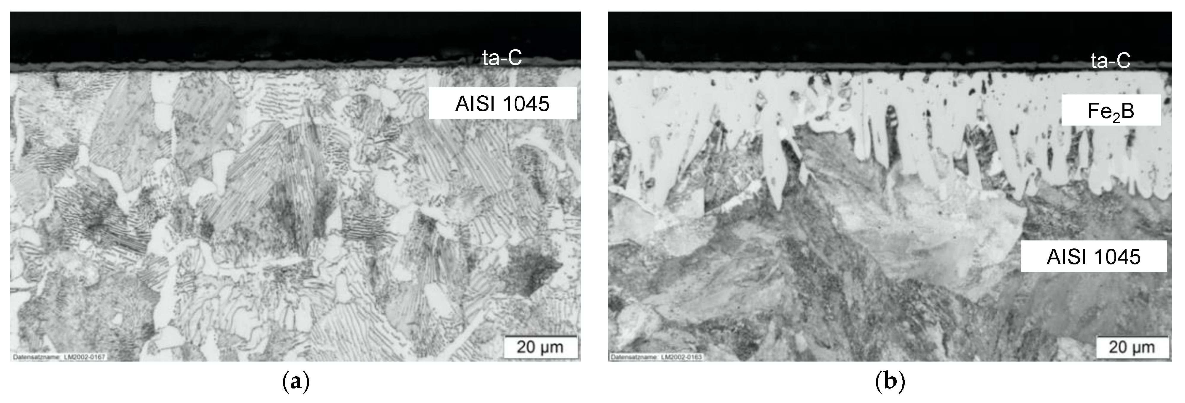
3.1. Sample Structures and Coatings Adhesion

The average thickness of the borided layer was 58 μm. The cross section in Figure 2b shows typical ‘boride teeth’ for the Fe2B phase. The process parameters were chosen to suppress the growth of the brittle FeB phase and to promote the preferred Fe2B growth, which was shown to enhance the adhesion of subsequent coatings by Kartal et al. [13,15,27]. Comparing St-B-C and St-C samples (Figure 2a,b, respectively) shows influences of the high temperature boriding on the microstructure of the substrate. The substrate’s microstructure for St-B-C was found to be mainly pearlitic and more coarse-grained. The hardness of the boride layer was about 1200 HV0.05 and 265 HV0.1 for the steel substrate. In comparison, the substrate’s hardness for the St-C sample was measured as 236 HV0.1 and displayed an evenly distributed ferritic-pearlitic microstructure (Figure 2a). The higher hardness of the St-B-C substrate is attributed to the high boriding process temperature, which induces phase and structural change. The thickness of the deposited ta-C film was approximately 2 μm with a Young’s modulus of 320 GPa.
The adhesion of the St-C sample corresponded to acceptable HF1 failure according to VDI 3198 [32], characterized by perpendicular cracks and no ta-C delamination around the Rockwell-C indent’s perimeter, as shown in Figure 3a,c. The adhesion for the duplex-treated sample St-B-C was found with HF2 (Figure 3b,d), which is characterized by more frequent perpendicular cracks and additional radial cracks around the indent’s edge without any coating delamination. Both failure modes are acceptable according to the standard. This result suggests that there are differences in the adhesion between the ta-C coating directly deposited onto the steel and the borided layer, implying that the interfacial adhesion for the latter is not as strong as the first described coating system.

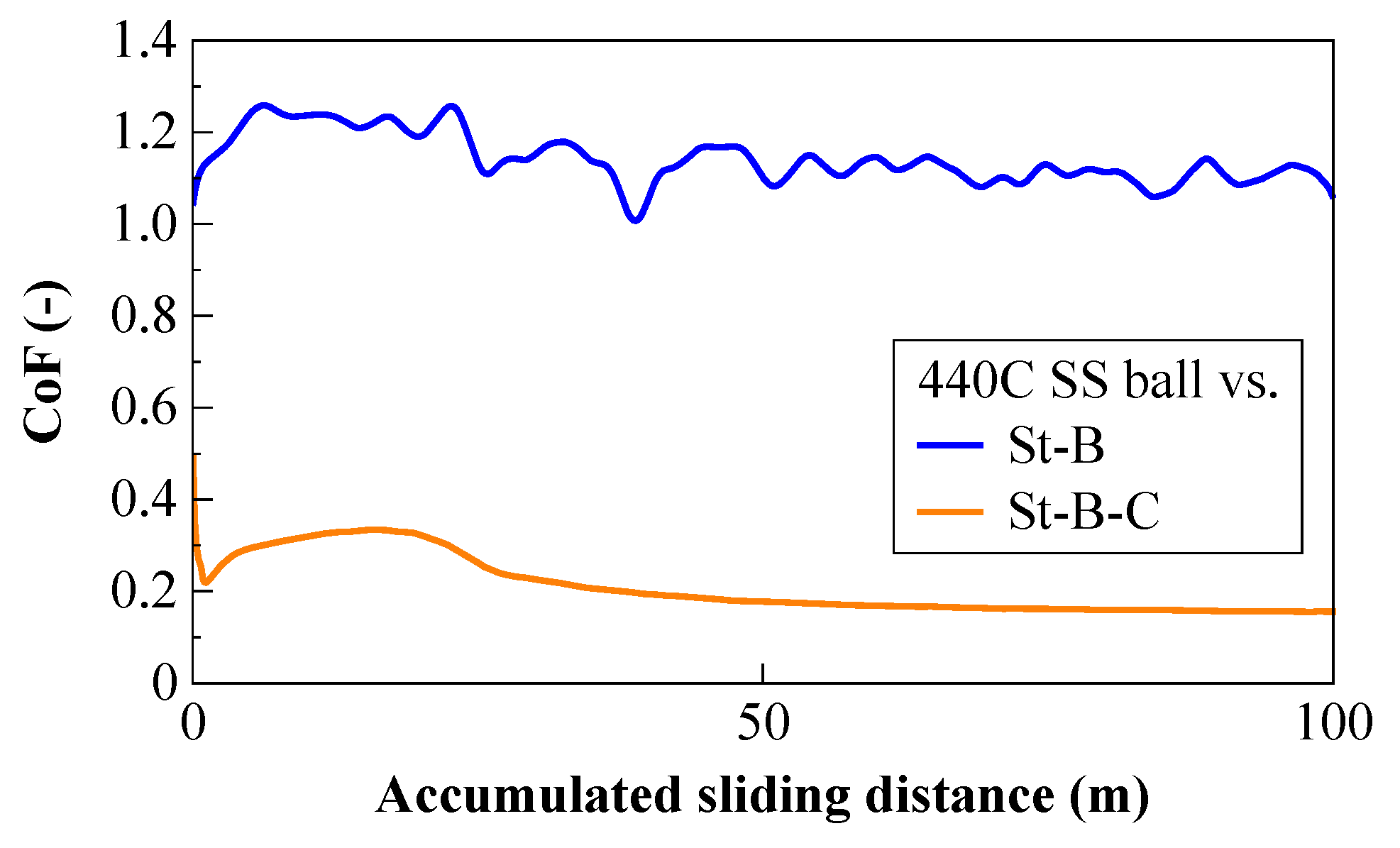
3.2. Tribological Testing and Wear Measurements

The CoF with the 440C SS counter ball proved to be much lower for the duplex-treated St-B-C sample than for the single-layer borided St-B sample. After a running distance of around 25 m, a steady CoF of 1.19 was reached for the borided sample (Figure 4). The CoF for the St-B-C sample, on the other hand, reached a CoF of 0.14 ± 0.02.
While the wear track for the duplex-treated sample was almost undetectable after a run distance of 100 m (12,500 cycles), the borided sample showed significant wear (Figure 5a,b, top) with a wear track depth as deep as 7.8 µm. Based on profilometric analysis of the St-B-C wear track, the occurring wear was remarkably lower than on the borided surface (Figure 5a,b, bottom). The wear rates were found with 6 × 10⁻⁸ mm3·N−1·m−1 for the duplex treatment and 5 × 10⁻⁵ mm3·N−1·m−1 for the borided surface. Wear on the St-B-C sample occurred only in the ta-C coating, as determined by the wear track depth of about 180 nm.
The applied contact pressures of 1 GPa in these tests exceeded real-world loads for tribological systems in tough conditions: In automotive high-pressure fuel injection systems, where diamond-like carbon coatings are being applied, typical contact pressures are significantly lower than 0.2 GPa [35]. Furthermore, in manufacturing, such as stamping of sheet metal, steady contact pressures usually do not exceed 0.6 GPa [36].

3.3. Finite Element Modeling and Impact Test

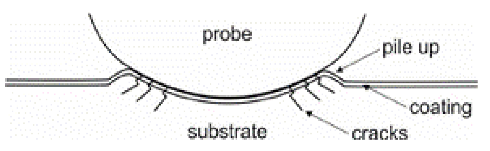
3.3.1. Finite-Element Modeling of Nanoindentation
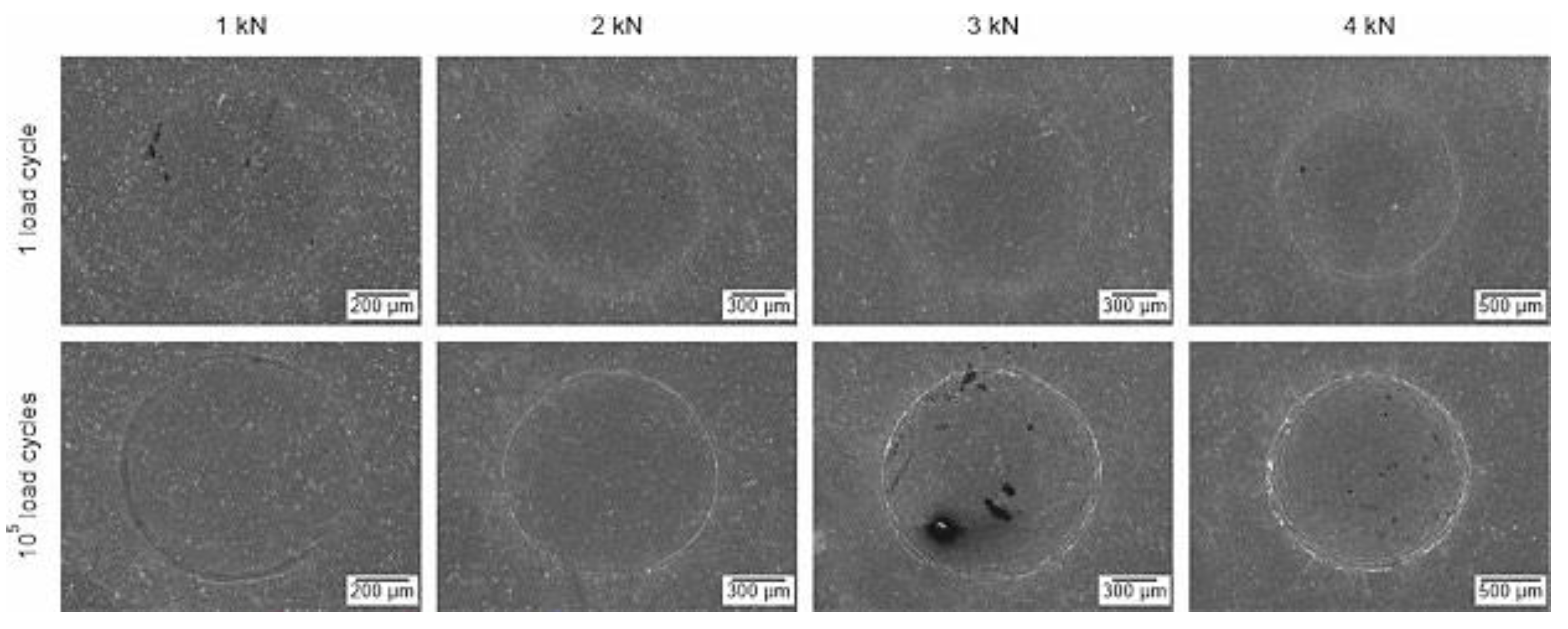
To model the mechanical behavior and stress distribution for all introduced material systems, Figure 6a shows the resulting indentation depth as a measure of the deformation when applying a constant force of 1.2 mN. As expected, the deformation for the untreated and uncoated substrate (St) was the highest, while the resulting indentation depth for St-B-C was the smallest. Furthermore, the resulting deformation of the St-B system was comparable to the St-B-C sample and smaller than the St-C system. This shows the importance of the borided layer for increasing the resistance to deformation. The force that was required to deform the various material systems to induce a deformation of 14 nm is plotted in Figure 6b. St and St-C required a much smaller force than St-B and St-B-C, which shows that the substrate is the limiting factor in resistance to deformation. St-B and St-B-C were in a similar force range, with St-B-C requiring a slightly higher force to induce the same deformation.

3.3.2. Impact Test

The spot diameters of all impact tests were measured for both coating systems. The results are shown in Figure 7 for all generated impacts (total of two for each cycle and load condition as mentioned in Section 2, Materials and Methods). With increasing load and number of load cycles, the resulting spot diameters also increased. Load was found to be the dominant factor, with the number of cycles (1 to 105) causing only modest increases in spot diameter. Furthermore, measured diameters of the St-C were higher in comparison to St-B-C specimens, except for 1 kN and low cycles. It can be seen that the differences increased for higher loads. These results are in good agreement with the FEA modeled deformations.
All impacts of the tested specimens were analyzed by SEM in order to compare the damage evolution of the coating systems. For comparison, the spots generated by loading 1 and 105 cycles of one specimen of every coating system are shown in Figure 8 and Figure 9 for St-C and Figure 10 and Figure 11 for St-B-C. In the case of the St-C specimen, it was observed that after one loading cycle there was no crack initiation in the coating as long as the load was 2 kN or less. At a 3 kN load, very small cracks with a length of a few µm could be found (Figure 9a). After applying at least 10³ loading cycles, small cracks and irregularities at the ta-C surface were found for every load. With increasing load and cycles, the length of cracks and area of spalling increased. After applying 105 loading cycles at 4 kN load, the coating was significantly damaged, as shown in Figure 9b. Over the whole impact area, especially at the pile up (Figure 1) of the round impact, very long cracks in tangential direction could be found. Cracks in the radial direction and multiple spalling regions were observed at the outer edge of the impact zone. There were no cracks visible in the substrate.
For the St-B-C specimens (Figure 10), small cracks were found after applying one loading cycle at 2 kN load (Figure 11a) or at least 10³ loading cycles. In comparison to the St-C specimen, the damage evolution with increasing load and cycles was more intense. After applying 105 loading cycles at 4 kN load, numerous widely opened cracks in the coating and also in the substrate were visible, as is shown in Figure 11b. Tangential orientated cracks in the impact zone and radial cracks at the outer edge of the pile up were found as well. The observed damage patterns of St-C and St-B-C were comparable to the damage model established by Zha et al. [25].
The damage evolution predominantly evolved at the pile-up of the impact zone. Therefore, selected cross sections of typical pile-up areas are presented in Figure 12. In Figure 12a, the pile up of a St-C specimen loaded with 3 kN for 105 cycles is illustrated. The substrate shows a smooth surface, and the coating is completely connected to the substrate, even in the areas of maximum plastic deformation. It can therefore be concluded that the ta-C coating has evidently an excellent adhesive strength. However, the plastic deformation led to high tensile stresses in the surface of the coating and caused several cracks in the ta-C. There were no cracks or any other signs of defects in the substrate.
In contrast, the boride layer of the hybrid coating system shows multiple cracks in the pile-up zone of the impact. Those cracks were already observed after one load cycle up to 3 kN and caused cracks in the ta-C layer (Figure 12b). The size and number of those cracks increased by an increasing number of load cycles (Figure 12c). In comparison to the St-C system, the St-B-C system showed more and larger cracks in the ta-C coating at the same load levels, although the plastic deformation was significantly smaller. The cracks in the ta-C coating could be a result of cracks in the boride layer. Additionally, there were several internal defects and pitting visible in the boride layer. No spalling of the coatings was visible in the cross sections.
The results of the cyclic impact tests revealed clear differences in the mechanical behavior of the tested coating systems St-C and St-B-C. The evaluation of the impact diameters showed a higher resistance to indentation of the St-B-C coating system compared to the St-C system during the fatigue tests. This was primarily attributed to the higher hardness of the boride layer reaching 1200 HV0.05, which partially relieves the ta-C coating compared to the non-boride substrate with 236 HV0.1. Additionally, the boriding process transformed the microstructure of the substrate in a nonequilibrium condition. This change slightly increases the hardness of the substrate which contributes to the resistance to indentation. This effect illustrates the importance of an integrated consideration of the manufacturing process in evaluating the behavior of a coating. In the case of medium external loads, the higher resistance to indentation of the St-B-C coating system offers advantages in industrial applications where precision is critical, like bearings or slide rails. Furthermore, the applied loads resulted in Hertzian contact stresses of approximately 7–12 GPa (1–4 kN, respectively) at one load cycle for both coating systems. These contact stresses exceed common contact stresses that are applied on, e.g., wind turbine bearings in test setups such as micropitting rigs [37] and rolling bearing assemblies [38].
The abovementioned advantage of the hybrid coating system is accompanied by a higher tendency for crack initiation. It was observed that the ta-C coating of St-C specimens was able to bear high loads up to 4 kN without critical failing, while the St-B-C specimens showed multiple cracks and spalling of the ta-C coating. The evaluation of the test results suggests that the location of crack initiation might be the boride layer or the ta-C/boride interface. The process led to internal irregularities and surface defects in the boride layer. Those kinds of defects could act as a stress concentration and function as the preferable location of crack initiation.

3.4. Resistance to Pinhole Corrosion

Exposing samples of the St-C and St-B-C type to 15% HCl acid for 3 h revealed delamination of the carbon coating in both cases. While delamination for the St-C sample was expected due to pinhole corrosion, the St-B-C sample was anticipated to withstand the exposure because the corrosion-resistant boride layer should prevent any corrosion products from forming under the surface coating.
The sample suggested that the delamination occurred at the interface between the boride and Cr interlayer. Therefore, new samples without the Cr interlayer were introduced, which were named St-noCr-C and St-B-noCr-C.
Pinhole corrosion for sample St-noCr-C resulted in typical corrosion products in the form of pits on the steel surface as well as the delamination of the ta-C coating, as shown in Figure 13. EDS analysis in area A (Figure 13b) confirmed the existence of corrosion products with an elemental composition of 67% Fe, 22% O, 8% C and 3% Cl, whereas area B in Figure 13b only consisted of Fe, C and minor traces of O.
Figure 14 shows the surface morphology of the St-B-noCr-C sample before (Figure 14b) and after (Figure 14c) exposure to the HCl solution. Comparing the overall appearance of St-noCr-C in Figure 13a and St-B-noCr-C in Figure 14a, it becomes obvious that St-B-noCr-C shows no coating delamination. The surface composition and morphology before and after exposure of St-B-noCr-C show no significant differences, with the surface mainly consisting of carbon and some traces of oxygen.
The results of the corrosion study revealed that the borided layer will protect the substrate from pinhole corrosion under a 15% HCl solution environment despite the fact that pinholes are present in the ta-C coating. However, this is only the case if a Cr interlayer is neglected and the ta-C coating is deposited directly on the Fe2B interface. As a conclusion, the Fe2B layer represents a possible candidate for an interlayer for diamond-like carbon coatings on steel substrates, as has already been shown to work for polycrystalline diamond coatings on steel substrates [39,40]. A possible option to increase the corrosion resistance without a potential loss in the adhesion of ta-C to boride is to introduce a silicon interlayer, which is commonly used as an adhesion layer in DLC and nitride duplex treatments [1,6,41]. Doped (dopants such as Si and Cu) diamond-like carbon films have been shown to also increase the resistance to pinhole corrosion [42,43].

4. Conclusions

Ta-C coatings, deposited by laser pulse-controlled cathodic arc evaporation onto electrochemically borided AISI 1045 low carbon steels with a Cr interlayer, showed acceptable HF2 adhesion according to a VDI 3198 Rockwell-C adhesion test. The duplex-treated sample St-B-C shows promising performance advantages compared with either the single-layer carbon coating or boride treatment.
The coefficient of friction is significantly decreased from 1.19 for St-B to 0.14 for St-B-C under a Hertzian contact pressure of 1 GPa and a steel counter body. Under the same conditions, the wear rate dropped from 5 × 10⁻⁵ mm3·N−1·m−1 to 6 × 10⁻⁸ mm3·N−1·m−1 for St-B and St-B-C, respectively.
The impact test results agree with the conducted FEA nanoindentation modeling: The duplex-treated sample experiences a higher resistance against plastic deformation compared to the St-C sample shown through the decreased impact diameters. This can be mainly attributed to the borided layer, which provides a sufficient support for the hard ta-C top coating. However, the higher resistance to plastic deformation might be causing the tendency for crack initiation in the duplex-treated sample.
Corrosion studies under a 3 h exposure to 15% HCl at room temperature revealed that the ta-C coating delaminates in the case of the St-C and St-B-C sample. While pinhole corrosion is expected for the St-C sample, the delamination of the ta-C coating in case of the St-B-C sample might be attributed to the Cr interlayer, which dissolves under the named conditions. However, the corrosion resistance of the St-B-C system is greatly improved when eliminating the Cr interlayer.
The present study provides proof of concept of the boride-carbon hybrid technology by combining low-friction, wear, impact fatigue and corrosion resistance in one solution for real-world applications. While the resistance of the ta-C coating under high cyclic loads (up to 4 kN) is not fully exploited, the boride layer’s yield strength seems to be exceeded under such conditions. Tailoring the boride layer towards higher load-bearing capacities and investigating the interface between ta-C and boride is inevitable for the success of this technology. This could potentially further increase the adhesion and corrosion resistance of the complete hybrid system.

Author Contributions

Design and execution of tribological and corrosion tests, writing—original draft preparation, N.B.; FEA simulation, Y.S.K. and Z.H.; design and execution of impact tests, writing and reviewing—original draft preparation, A.T.Z., R.K. and M.Z.; ta-C depositions, L.H.; boriding, O.L.E.; funding acquisition, project administration, reviewing of draft and supervision, A.E., T.S. and Q.-H.F. All authors have read and agreed to the published version of the manuscript.

Funding

This material is based upon work supported by the U.S. Department of Energy’s Office of Energy Efficiency and Renewable Energy (EERE) under the Advanced Manufacturing Office award number DE-EE0008320. The primary awardee is Michigan State University and the sub-awardees are Fraunhofer USA, Inc. and Argonne National Laboratory.

Institutional Review Board Statement

Not applicable.

Informed Consent Statement

Not applicable.

Data Availability Statement

Not applicable.

Conflicts of Interest

The authors declare no conflict of interest. This report was prepared as an account of work sponsored by an agency of the United States Government. Neither the United States Government nor any agency thereof, nor any of its employees, makes any warranty, express or implied, or assumes any legal liability or responsibility for the accuracy, completeness, or usefulness of any information, apparatus, product, or process disclosed, or represents that its use would not infringe privately owned rights. Reference herein to any specific commercial product, process, or service by trade name, trademark, manufacturer, or otherwise does not necessarily constitute or imply its endorsement, recommendation, or favoring by the United States Government or any agency thereof. The views and opinions of authors expressed herein do not necessarily state or reflect those of the United States Government or any agency thereof.

References

  1. Dalibon, E.L.; Trava-Airoldi, V.; Pereira, L.A.; Cabo, A.; Brühl, S.P. Wear resistance of nitrided and DLC coated PH stainless steel. Surf. Coat. Technol. 2014, 255, 22–27. [Google Scholar] [CrossRef]
  2. Ueda, N.; Yamauchi, N.; Sone, T.; Okamoto, A.; Tsujikawa, M. DLC film coating on plasma-carburized austenitic stainless steel. Surf. Coat. Technol. 2007, 201, 5487–5492. [Google Scholar] [CrossRef]
  3. Yerokhin, A.; Leyland, A.; Tsotsos, C.; Wilson, A.; Nie, X.; Matthews, A. Duplex surface treatments combining plasma electrolytic nitrocarburising and plasma-immersion ion-assisted deposition. Surf. Coat. Technol. 2001, 142–144, 1129–1136. [Google Scholar] [CrossRef]
  4. Tsotsos, C.; Yerokhin, A.; Wilson, A.; Leyland, A.; Matthews, A. Tribological evaluation of AISI 304 stainless steel duplex treated by plasma electrolytic nitrocarburising and diamond-like carbon coating. Wear 2002, 253, 986–993. [Google Scholar] [CrossRef]
  5. Boromei, I.; Ceschini, L.; Marconi, A.; Martini, C. A duplex treatment to improve the sliding behavior of AISI 316L: Low-temperature carburizing with a DLC (a-C:H) topcoat. Wear 2013, 302, 899–908. [Google Scholar] [CrossRef]
  6. Dekempeneer, E.; Poirier, L.; Lebrun, J.; Pasgrimaud, A.; Desalos, Y.; Balanck, F. Development of an industrialised DLC duplex treatment process. Surf. Coat. Technol. 2002, 151-152, 462–465. [Google Scholar] [CrossRef]
  7. Kyzioł, K.; Mędala, M.; Kaczmarek, Ł. Influence of plasmochemical modification of Al–Cu–Mg alloys on surface structure and functional properties. Vacuum 2014, 105, 52–58. [Google Scholar] [CrossRef]
  8. Gawel, R.; Kyzioł, K.; Jurasz, Z.; Grzesik, Z. Oxidation resistance of valve steels covered with thin SiC coatings, obtained by RF CVD. Corros. Sci. 2018, 145, 16–25. [Google Scholar] [CrossRef]
  9. Litoria, A.K.; Joshi, A.A.; Joshi, M.D.; Dixit, G.; Singh, D.; Hosmani, S.S. Wear behaviour of boronized and duplex-treated AISI 4140 steel against DLC-coated boronized AISI 4140 disc. Surf. Eng. 2018, 35, 370–377. [Google Scholar] [CrossRef]
  10. Erdemir, A.; Eryilmaz, O.; Sista, V. Ultra-Fast Boriding for Improved Energy Efficiency and Reduced Emissions in Materials Processing; U.S. Department of Energy: Oak Ridge, TN, USA, 2008. [Google Scholar]
  11. Sinha, A.K. Boriding (Boronizing) of steels. In ASM Handbook Steel Heat Treating Fundamentals and Processes, 10th ed.; ASM International: Metals Park, OH, USA, 1991; pp. 437–447. [Google Scholar]
  12. Matuschka, A. Boronizing; Heyden Publications: Philadelphia, PA, USA, 1980. [Google Scholar]
  13. Kartal, G.; Kahvecioglu, O.; Timur, S. Investigating the morphology and corrosion behavior of electrochemically borided steel. Surf. Coat. Technol. 2006, 200, 3590–3593. [Google Scholar] [CrossRef]
  14. Kartal, G.; Eryilmaz, O.; Krumdick, G.; Erdemir, A.; Timur, S. Kinetics of electrochemical boriding of low carbon steel. Appl. Surf. Sci. 2011, 257, 6928–6934. [Google Scholar] [CrossRef]
  15. Kartal, G.; Timur, S.; Eryilmaz, O.; Erdemir, A. Influence of process duration on structure and chemistry of borided low carbon steel. Surf. Coat. Technol. 2010, 205, 1578–1583. [Google Scholar] [CrossRef]
  16. Knotek, O.; Bosserhoff, B.; Schrey, A.; Leyendecker, T.; Lemmer, O.; Esser, S. A new technique for testing the impact load of thin films: The coating impact test. Surf. Coat. Technol. 1992, 54–55, 102–107. [Google Scholar] [CrossRef]
  17. Heinke, W.; Leyland, A.; Matthews, A.; Berg, G.; Friedrich, C.; Broszeit, E. Evaluation of PVD nitride coatings, using impact, scratch and Rockwell-C adhesion tests. Thin Solid Films 1995, 270, 431–438. [Google Scholar] [CrossRef]
  18. Lugscheider, E.; Knotek, O.; Wolff, C.; Barwulf, S. Structure and properties of PVD-coatings by means of impact tester. Surf. Coat. Technol. 1999, 116–119, 141–146. [Google Scholar] [CrossRef]
  19. Knotek, O.; Lugscheider, E.; Löffler, F.; Schrey, A.; Bosserhoff, B. Behaviour of CVD and PVD coatings under impact load. Surf. Coat. Technol. 1994, 68–69, 253–258. [Google Scholar] [CrossRef]
  20. Bantle, R.; Matthews, A. Investigation into the impact wear behaviour of ceramic coatings. Surf. Coat. Technol. 1995, 74–75, 857–868. [Google Scholar] [CrossRef]
  21. Batista, J.; Godoy, C.; Matthews, A.; Godoy, G.C. Impact testing of duplex and non-duplex (Ti,Al)N and Cr–N PVD coatings. Surf. Coat. Technol. 2003, 163–164, 353–361. [Google Scholar] [CrossRef]
  22. Lamri, S.; Langlade, C.; Kermouche, G. Damage phenomena of thin hard coatings submitted to repeated impacts: Influence of the substrate and film properties. Mater. Sci. Eng. A 2013, 560, 296–305. [Google Scholar] [CrossRef]
  23. Beake, B.; Goodes, S.; Smith, J. Micro-Impact Testing: A New Technique for investigating thin film toughness, adhesion, erosive wear resistance, and dynamic hardness. Surf. Eng. 2001, 17, 187–192. [Google Scholar] [CrossRef]
  24. Beake, B.D.; García, M.J.I.; Smith, J.F. Micro-impact testing: A new technique for investigating fracture toughness. Thin Solid Films 2001, 398–399, 438–443. [Google Scholar] [CrossRef]
  25. Zha, X.; Jiang, F.; Xu, X. Investigating the high frequency fatigue failure mechanisms of mono and multilayer PVD coatings by the cyclic impact tests. Surf. Coat. Technol. 2018, 344, 689–701. [Google Scholar] [CrossRef]
  26. Kartal, G.; Timur, S.; Sista, V.; Eryilmaz, O.; Erdemir, A. The growth of single Fe2B phase on low carbon steel via phase homogenization in electrochemical boriding (PHEB). Surf. Coat. Technol. 2011, 206, 2005–2011. [Google Scholar] [CrossRef]
  27. Kartal, G.; Timur, S.; Urgen, M.; Erdemir, A. Electrochemical boriding of titanium for improved mechanical properties. Surf. Coat. Technol. 2010, 204, 3935–3939. [Google Scholar] [CrossRef]
  28. Scheibe, H.-J.; Schultrich, B.; Drescher, D. Laser-induced vacuum arc (Laser Arc) and its application for deposition of hard amorphous carbon films. Surf. Coat. Technol. 1995, 74-75, 813–818. [Google Scholar] [CrossRef]
  29. Scheibe, H.-J.; Drescher, D.; Schultrich, B.; Falz, M.; Leonhardt, G.; Wilberg, R. The laser-arc: A new industrial technology for effective deposition of hard amorphous carbon films. Surf. Coat. Technol. 1996, 85, 209–214. [Google Scholar] [CrossRef]
  30. Schultrich, B.; Scheibe, H.-J.; Grandremy, G.; Drescher, D.; Schneider, D. Elastic modulus as a measure of diamond likeness and hardness of amorphous carbon films. Diam. Relat. Mater. 1996, 5, 914–918. [Google Scholar] [CrossRef]
  31. Schneider, D.; Schwarz, T.; Scheibe, H.-J.; Panzner, M. Non-destructive evaluation of diamond and diamond-like carbon films by laser induced surface acoustic waves. Thin Solid Films 1997, 295, 107–116. [Google Scholar] [CrossRef]
  32. Vidakis, N.; Antoniadis, A.; Bilalis, N. The VDI 3198 indentation test evaluation of a reliable qualitative control for layered compounds. J. Mater. Process. Technol. 2003, 143-144, 481–485. [Google Scholar] [CrossRef]
  33. Hu, Z.; Lynne, K.J.; Markondapatnaikuni, S.P.; Delfanian, F. Material elastic–plastic property characterization by nanoindentation testing coupled with computer modeling. Mater. Sci. Eng. A 2013, 587, 268–282. [Google Scholar] [CrossRef]
  34. Cabezas, E.E.; Celentano, D.J. Experimental and numerical analysis of the tensile test using sheet specimens. Finite Elem. Anal. Des. 2004, 40, 555–575. [Google Scholar] [CrossRef] [Green Version]
  35. Treutler, C.P. Industrial use of plasma-deposited coatings for components of automotive fuel injection systems. Surf. Coat. Technol. 2005, 200, 1969–1975. [Google Scholar] [CrossRef]
  36. Pereira, M.P.; Yan, W.; Rolfe, B.F. Contact pressure evolution and its relation to wear in sheet metal forming. Wear 2008, 265, 1687–1699. [Google Scholar] [CrossRef]
  37. Gould, B.; Greco, A. Investigating the process of white etching crack initiation in bearing steel. Tribol. Lett. 2016, 62, 1–14. [Google Scholar] [CrossRef]
  38. Fernandes, C.M.; Martins, R.C.; Seabra, J.H. Friction torque of thrust ball bearings lubricated with wind turbine gear oils. Tribol. Int. 2013, 58, 47–54. [Google Scholar] [CrossRef]
  39. Damm, D.D.; Contin, A.; Barbieri, F.C.; Trava-Airoldi, V.J.; Barquete, D.M.; Corat, E.J. Interlayers Applied to CVD Diamond Deposition on Steel Substrate: A Review. Coatings 2017, 7, 141. [Google Scholar] [CrossRef] [Green Version]
  40. Buijnsters, J.; Shankar, P.; Gopalakrishnan, P.; Van Enckevort, W.; Schermer, J.; Ramakrishnan, S.; Ter Meulen, J. Diffusion-modified boride interlayers for chemical vapour deposition of low-residual-stress diamond films on steel substrates. Thin Solid Films 2003, 426, 85–93. [Google Scholar] [CrossRef]
  41. Meletis, E.; Erdemir, A.; Fenske, G. Tribological characteristics of DLC films and duplex plasma nitriding/DLC coating treatments. Surf. Coat. Technol. 1995, 73, 39–45. [Google Scholar] [CrossRef]
  42. Wu, Y.; Zhou, S.; Zhao, W.; Ouyang, L. Comparative corrosion resistance properties between (Cu, Ce)-DLC and Ti co-doped (Cu, Ce)/Ti-DLC films prepared via magnetron sputtering method. Chem. Phys. Lett. 2018, 705, 50–58. [Google Scholar] [CrossRef]
  43. Papakonstantinou, P.; Zhao, J.; Lemoine, P.; McAdams, E.; McLaughlin, J. The effects of Si incorporation on the electrochemical and nanomechanical properties of DLC thin films. Diam. Relat. Mater. 2002, 11, 1074–1080. [Google Scholar] [CrossRef]
Figure 1. Location of taken cross section of the impact spot with an indication of the individual zones and layers.
Coatings 11 00475 g001
Figure 2. Five percent Nital-etched cross sections of (a) ta-C-coated (St-C) and (b) electrochemically borided and ta-C-coated (St-B-C) AISI 1045 steel.
Coatings 11 00475 g002
Figure 3. Rockwell-C adhesion test according to VDI 3198: (a,c) ta-C-coated substrate (St-C); (b,d) Duplex treatment (St-B-C). Arrows in (c) point towards cracks.
Coatings 11 00475 g003
Figure 4. Coefficient of friction as a function of the accumulated sliding distance determined in the ball-on-disk setup using a 440C SS ball under dry conditions.
Coatings 11 00475 g004
Figure 5. Optical microscopy images (a) and cross-section profiles (b) of sample wear tracks for St-B and St-B-C.
Coatings 11 00475 g005
Figure 6. FEA modeling results of nanoindentation for (a) a constant applied force and the resulting deformation along the depth, and (b) a constant deformation along the depth and the corresponding force for all samples.
Coatings 11 00475 g006
Figure 7. Impact diameters of St-C (a) and St-B-C (b) at different load cycles (1, 103, 105) as a function of the applied load. The impact diameters for 1 load cycle for sample St-C could only be measured for one of the impacts due to their insignificance.
Coatings 11 00475 g007
Figure 8. SEM images of the impacts for 1 and 4 kN and load cycles of 1 and 105 for the single-layer St-C system.
Coatings 11 00475 g008
Figure 9. Failure patterns in the outer edge of the impact zone for St-C: (a) Impact area and crack for the impact created at 3 kN and 1 load cycle; (b) Outer edge of the impact zone with significant crack patterns and coating delamination after being subject to 105 cycles at 4 kN.
Coatings 11 00475 g009
Figure 10. SEM images of the impacts for 1 to 4 kN and load cycles of 1 and 105 for the duplex treated St-B-C sample.
Coatings 11 00475 g010
Figure 11. Failure patterns in the outer edge of the impact zone for St-B-C: (a) Impact area and crack for the impact created at 2 kN and 1 load cycle; (b) Outer edge of the impact zone with significant crack patterns and coating delamination after being subject to 105 cycles at 4 kN.
Coatings 11 00475 g011
Figure 12. Pile-up of impact zones of samples exposed to 3 kN: (a) St-C after 105 load cycles; (b) St-B-C after 1 load cycle and (c) St-B-C after 105 load cycles.
Coatings 11 00475 g012
Figure 13. St-noCr-C sample: (a) overall appearance; (b) SEM images after the exposure to 15% HCl for 3 h. Delamination of ta-C coating exposes corrosion pits on the steel substrate (left). A higher magnification of a corrosion pit is shown on the right.
Coatings 11 00475 g013
Figure 14. St-B-noCr-C sample: (a) overall appearance after exposure; (b) Surface morphology before exposure; (c) Surface morphology after exposure.
Coatings 11 00475 g014
Table 1. Samples prepared for this study with sample-ID.
Sample-IDAISI 1045 SteelBoridedta-C CoatingFinal Surface Finish
St-Bxx-Ra = 20–25 nm
St-Cx-x
St-B-Cxxx
Table 2. Material properties used in the FEA model.
MaterialsThickness (µm)Young’s Modulus (GPa)Poisson’s Ratio
Diamond indenter-11400.04
ta-C coating23000.30
Boride502000.17
1045 AISI substrate15880.30
Publisher’s Note: MDPI stays neutral with regard to jurisdictional claims in published maps and institutional affiliations.

