Article

Polymer-Cement Composites Glazing by Concentrated Solar Energy

1
Materials Engineering and Welding Department, Transilvania University of Brasov, 29 Eroilor Blvd., 500036 Brasov, Romania
2
Product Design, Mechatronics and Environmental Protection Department, Transilvania University of Brasov, 29 Eroilor Blvd., 500036 Brasov, Romania
3
Faculty of Civil Engineering, Istanbul Technical University, Maslak, Istanbul 34469, Turkey
4
Faculty of Mechanical Engineering, Gheorghe Asachi Technical University, 67 Prof. D. Mangeron Blvd., 700050 Iași, Romania
5
Technical Sciences Academy of Romania, 26 Dacia Blvd., 030167 Bucharest, Romania
*
Authors to whom correspondence should be addressed.
Coatings 2021, 11(3), 350; https://doi.org/10.3390/coatings11030350
Submission received: 9 February 2021 / Revised: 10 March 2021 / Accepted: 15 March 2021 / Published: 18 March 2021
(This article belongs to the Section Plasma Coatings, Surfaces & Interfaces)

Abstract

:
Macro defect free (MDF) cements are polymer-cement composites characterized by high biaxial flexural strength compared to traditional concrete, having as a drawback a low water resistance. Glazing these composite materials with an inorganic enamel containing TiO2 nano-particles has led to a high water-stable material with advanced photocatalytic properties. Classic glazing by thermal treatment of samples, at 1050 °C, requires energy consumption and long-time performing. The purpose of this paper is to test the use of solar radiation as a source of energy in the glazing process. A vertical axis solar furnace has been used, from PROMES-CNRS Solar Laboratory, Font-Romeu Odeillo, France, and it has been observed that a uniform appearance of the glaze coating has been achieved; it shows high scratch resistance, meaning a good hardness and adhesion to the substrate. The obtained film was also characterized by SEM, EDS and XRD, aiming to evidence the coat morphology, the TiO2 distribution and its crystallinity alteration, when compared to the samples obtained by classic thermal treatment. The conclusion of the paper is that using solar radiation in the MDF cement glazing process is a promising approach for obtaining multifunctional materials.

1. Introduction

Energy is one of the hottest topics in all of the life domains. Nowadays, life level asks for an increasing amount of energy, from inexhaustible sources that are easy to obtain and environmentally friendly. This is why scientists are looking for new energy sources and trying to adapt the actual technologies to the new ones or to completely change them.
Solar radiation is one of the most efficient non-conventional energies, fitting to all the actual requests of sustainable development of society. It is a clean source of energy, without the emission of particles (metals, carbon black, and soot) and harmful gases (volatile organic compounds VOC, oxides) [1]. A huge potential for industrial sectors represents the solar thermal energy. Shahjadi Hisan Farjana et al. identified all over the world the possible domains (mineral processing, manufacturing of chemical products, fabricating metal industries, agricultural industry, food industry, pharmaceutical industry, textile industry, paper industry, etc.) in which it can be applied [2]. Sharma et al. [3] highlight some processes in the medium and low temperature domain that can be successfully sustained by solar energy (surface treatments, melting, painting, sterilization, evaporation, cleaning, distillation, drying, pasteurization, etc.).
For producing fuel like syngas/hydrogen, the conventional processes depend on hydrocarbon resources. The gasification of biomass (thermochemical process) by using solar energy is a cleaner method, detailed by Lédé [4], Epstein et al. [5], Puig-Arnavat et al. [6], Nzihou et al. [7]. Cost and life cycle analyses, thermodynamic and experimental demonstrations of the gasification process are well exposed by Yadav et al. [8].
Concentrated solar energy fits well with metallic materials treatments, due to their high thermal conductivity. Upon solar sintering of AISI M2 (1.3343) high speed steel and reinforced high-speed steel vanadium-carbide, Herranz et al. [9,10] have shown that, by using solar energy, both sintering temperature and the process duration were significantly reduced. Prats et al. [11] analyzed different substrates used for solar tower receivers: Inconel 617, VM12, T91, T22, with different absorber coatings to perform accelerating aging tests. After 200 cycles, no unexpected degradation was observed on the coatings.
In industrial processes, welding is well suited to the use of concentrated solar energy, due to the very high temperatures required. Cambronero et al. [12] showed that the surface of the aluminum foam warms up during welding by solar energy, similarly to that of laser welding [13], and at high solar intensities, the aluminum starts to melt. Results concerning 6082 aluminum alloy welding are presented by Pantelis. The results obtained for this material are similar with those obtained by other researchers with other fusion welding methods [14]. Romero [15] demonstrates the possibility to obtain welded joints of Ti6Al4V alloy with a full penetration of welded tracks and a microstructure without defects. Flamanta et al. [16] highlighted the use of concentrated solar energy as competitive technique compared to plasma or laser systems in hardening of the steel surface.
Another application of concentrated solar energy is testing the aging resistance of materials, for example, materials that are used for photovoltaic devices. Tromholt et al. have tested five types of polymers [17,18] at solar intensities equivalent to 1...200 suns [19], following photochemical stability. The degradation mechanisms of each material in a very short time were presented. For a two-layer material (metal + paint coating) used in the receivers of concentrate solar power (CSP) plants as absorber materials, the accelerating aging using concentrated solar energy was studied. The paint coating must be carefully vitrified to obtain optimal absorption properties [20]. A square honeycomb SiCSi structure usually used in CSP plants as an absorber material was thermally treated and thermo-radiative properties were recorded [21]. Ceballos-Mendivil et al. [22] synthesized silicon carbide, in five steps, using solar energy in the last two with lower CO2 emissions during the process.
Sierra and Vazquez [23] studied the carbon steel coating with NiAl, using concentrated solar energy. In a few seconds, they obtained a good coating adhesion, proving the efficiency of this process.
Solar techniques were then extended to processes performed in ceramic industry, due to the high temperature needed. For example, Plaza et al. have demonstrated [24] the opportunity of the solar energy uses to the most common processes. Temperatures up to 1100 °C were obtained in a reproducible way. A comparative study of the sintering process in electric furnaces and in furnaces using solar energy was presented by Roman et al. [25] in order to establish if solar action could provide dense ceramic bodies. Alumina powders were used. After solar sintering, the material density increased and an important grain growth was observed. Good results in the sintering of magnesium titanate-based ceramics were obtained using solar furnace, by Apostol et al. [26]. Ceramic samples were sintered in air at 1100 °C, for periods between 16 min and 3 h. SEM and XRD analyses demonstrated that the processing temperature can be reduced from 1400 °C (in classic route) to 1100 °C (in solar furnace). The SEM images reveal a uniform grain structure and a dense and pore-free microstructure obtained at 1100 °C.
Materials employed in building industry (cements and concrete) are those that are beneficiaries of the concentrated solar energy use. The building industry is constantly developing, therefore the discovery of new materials or improving the existing ones with photocatalytic properties enhancing weathering, wearing and scratching resistance, is always a challenge for researchers in this field. According to S. Rashidi [27,28,29], solar energy fits very well with porous materials.
Discussions on using a new source of energy, such as solar radiation, have to also mention the disadvantages of this type of heating, which are related to its discontinuous use (only during the day time), the location limitations to only sunny areas having a constancy of solar radiation (Africa, Middle East, the deserts of Australia, India, Pakistan) and high initial investments [1,30].
Macro defect free cements represent ceramic-polymer composite materials with better mechanical resistance than traditional ones [31,32,33,34,35,36,37]. The surface hardness and scratch resistance of these materials could be improved by glazing. The glazing process involves typically heating a glaze-forming slurry or solution applied to the surface of a ceramic material or ceramic matrix composite to temperatures in the range of 900–1500 °C, which is usually performed by heating in an electric furnace. Depending on the annealing period and cooling speed, coatings of various crystallinity can be obtained. Usually, a mixture of an amorphous (glassy) with a crystalline phase is preferred. The amorphous matrix generally decreases the wear coefficient of the material, while the crystalline phase increases surface roughness [38,39].
Glazing of MDF cements with silicate-based formulations usually leads to predominantly amorphous glazes. By adding ceramic nanoparticles in the glaze, these act as nucleating agents that promote glaze crystallization. Moreover, nanoparticles can lead to an increase in the adherence of the glaze with the substrate and can provide additional functionality, texture and color to the glaze [40,41].
Conventional furnace glazing requires a high amount of energy input, low efficiencies (the whole material is heat-treated instead of only the surface) and could have as drawback for the modification in the chemistry of the ceramic substrate, especially in the case of MDF. Glazing could be better achieved by using a concentrated energy source, among which concentrated solar energy has recently proven useful in obtaining vitreous materials by Romero et al. [42].
In [43], the processing of partially fired, commercially available white clay and porcelain tiles was investigated, using a continuous roller laser furnace. It was revealed that high laser input energy values produce the melting of the material’s surface layer and its subsequent solidification as a thick compact surface layer. This layer is characterized by low surface roughness, without open porosity, while the inner pores do not adversely affect the outer surface’s properties. Laser furnace processing also allows the surface to melt and resolidify, while avoiding the formation of cracks, the melting depth increasing rapidly as a function of the incubation energy. Comparing the laser glazing of two types of commercial porcelain with different crystalline content in [44] demonstrated the advantage of concentrated energy surface thermal treatment on surface roughness reduction.
The first aim of this study is to check the possibility of replacing the classic glazing heat treatment in conventional electric furnaces with the concentrated solar energy in the glazing process of MDF cement composites. A comparison between the properties of glazed cements obtained by both methods has been done on glazed layers under concentrated solar energy on MDF cements and to compare them with those obtained in the conventional electric furnace, in terms of glaze morphology, structure, adherence to the substrate, and scratch resistance. A commercial silicate-based glazing slurry was activated with TiO2 nanoparticles and was used as a glaze promoter both in conjunction with the conventional furnace and concentrated solar heat treatment. The results of this paper aim to establish the feasibility of concentrated solar heat treatment in obtaining well-fused glazed ceramic materials and represent only the first step in a broader study regarding these materials’ mechanical and surface properties.

2. Materials and Methods

2.1. Preparation of Polymer-Cement Composites Samples

MDF (macro defect free) polymer-cement composite samples were obtained by using a recipe, containing calcium aluminate cement, poly(vinyl alcohol) [PVA], glycerol and water, in different amounts, according to the prescription described in [45,46]; the components ratios were polymer to cement: 0.07; glycerol/polymer: 0.1; water/cement: 0.12. The special technology for obtaining polymer-cement composites with a dense structure, containing micro (10–50 μm) and nano pores (<10 μm) and the parameters details is presented in [46,47]. Finally, the obtained samples are of circular shape, with a diameter of 27.5 mm and a thickness of 2 mm.

2.2. Coating of MDF Samples

The composite samples were coated with a photocatalytic paste, which is a mixture between an ecological inorganic enamel, transparent and thixotropic, based on silica dispersed in water and containing acrylic compounds (Botz 9102, BOTZ GmbH Keramische Farben, Germany) and 7% TiO2 (Degussa P 25, anatase/rutile ratio of 3:1). More details are presented in the paper [45].

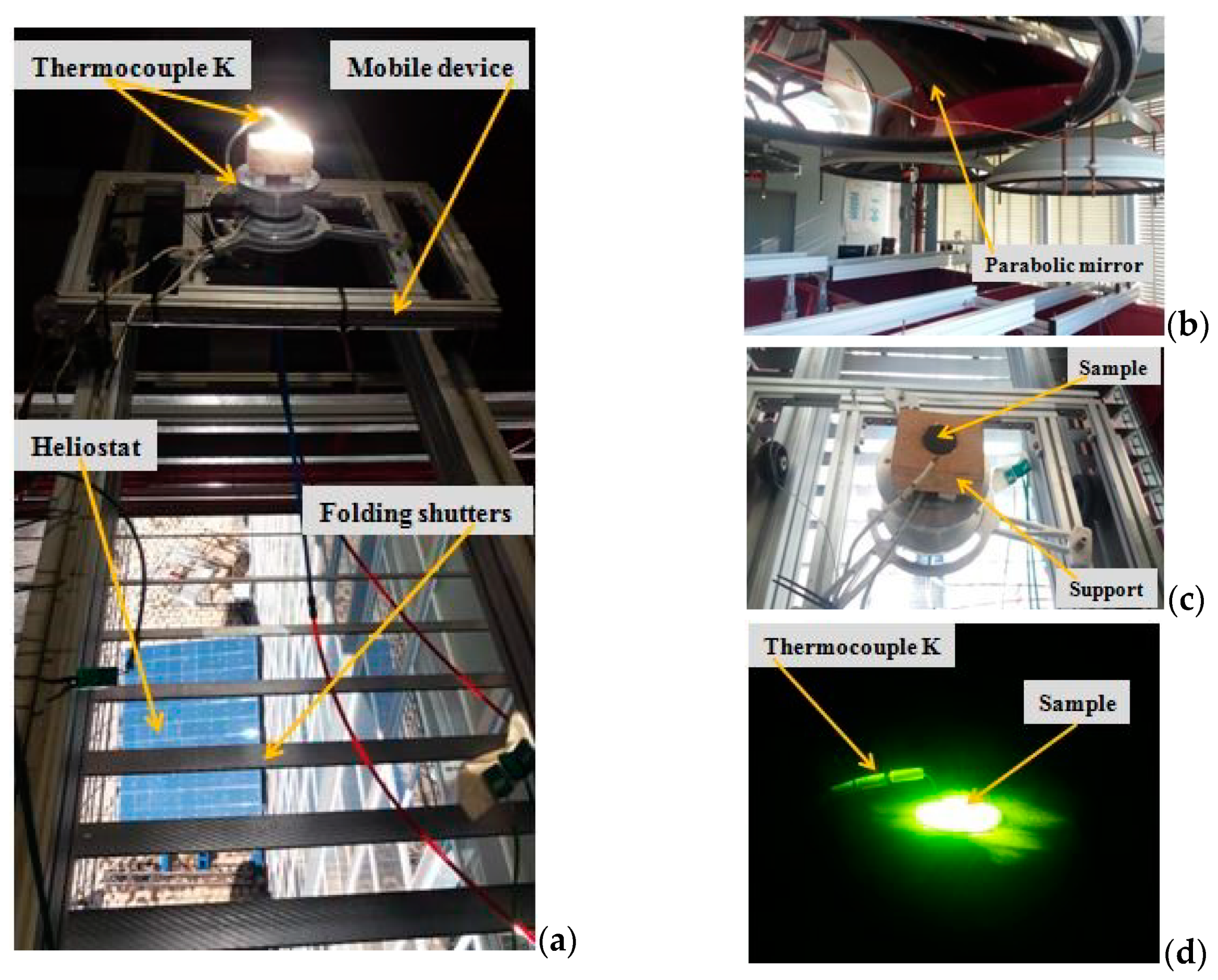
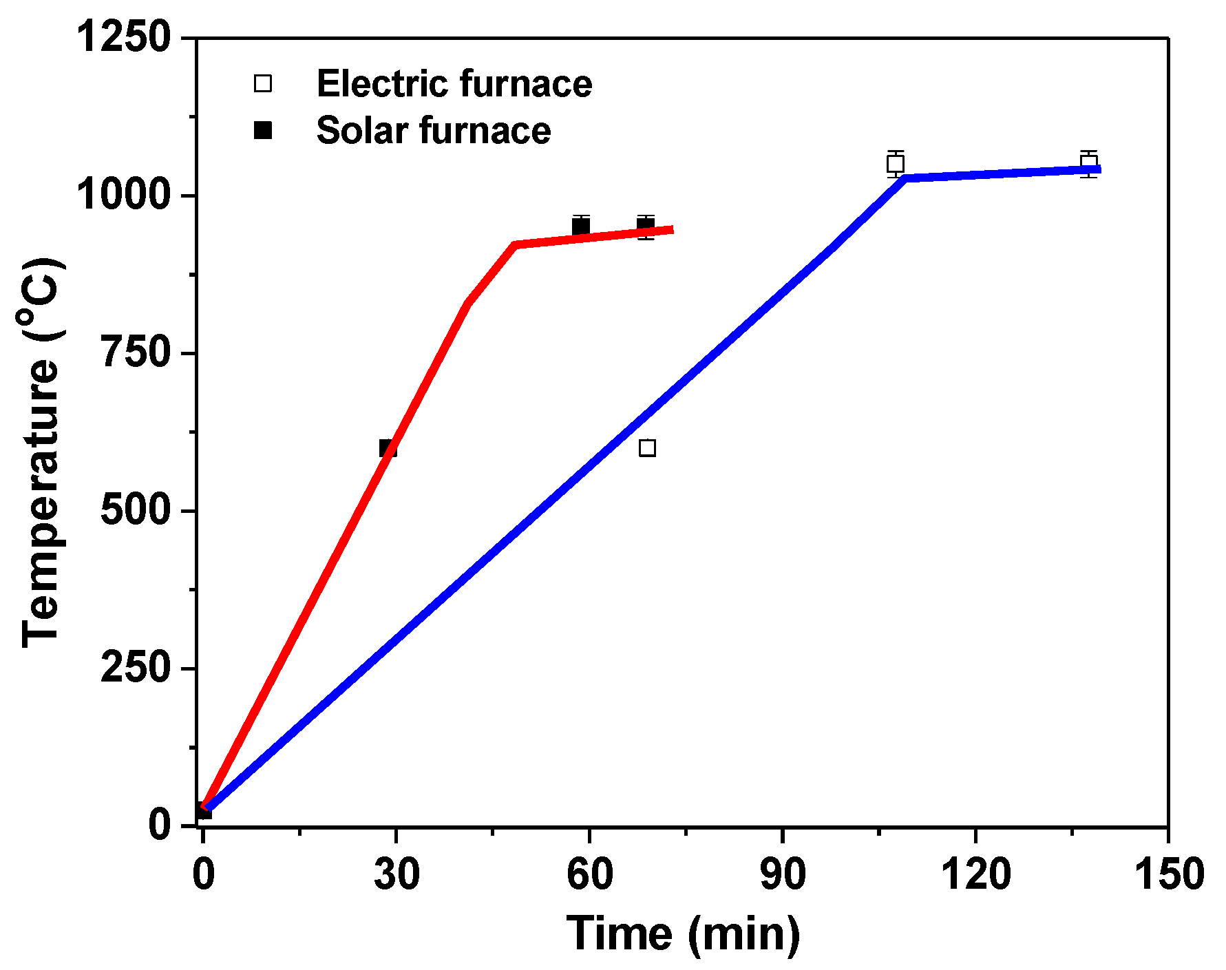
2.3. Glaze Formation by Thermal Treatment
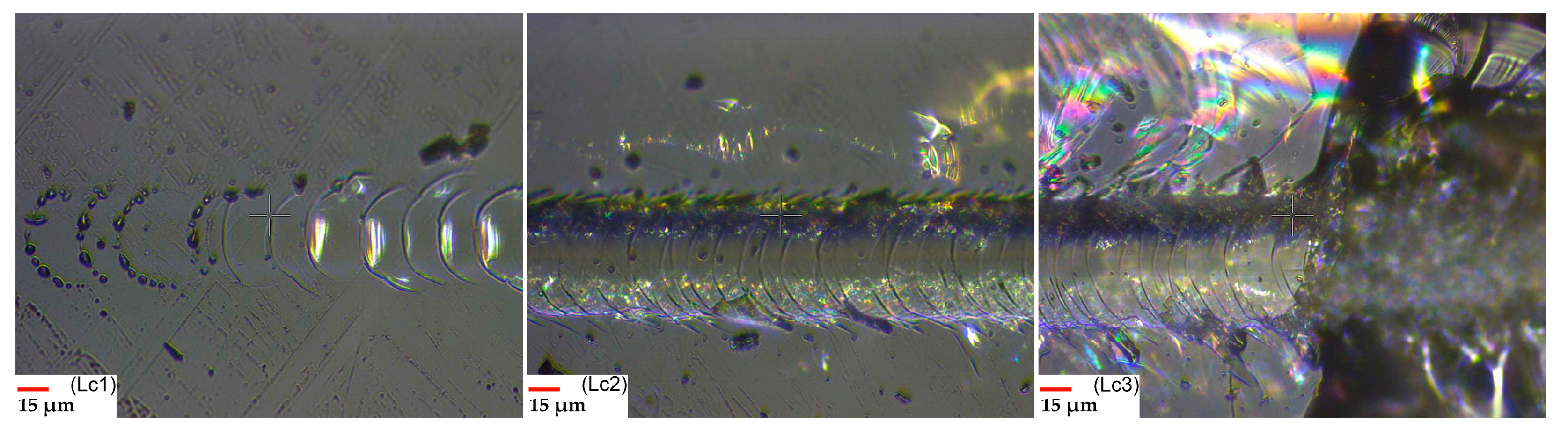
After thoroughly cleaning the samples surface with ethanol, the paste was applied by brushing. For glaze formation (water evaporation, polymer decomposition and silicates cross linking), the specimens were submitted to thermal treatment, by using two types of technologies: a classical treatment in an electric furnace and a non-conventional one, using concentrated solar energy. After glazing and firing, the mass for both types of firing technologies decreases. The using of the electric furnace affects the MFD substrate more intensely, while for the concentrated energy, the sudden evaporation of the dispersant from the glaze determines the entrainment of the silicate and generates an uneven deposition. For this technology, increasing the amount of brushed glaze aimed to obtain a uniform layer.
The classical furnace is produced by Caloris Group SA, Romania. Processes are controlled with an INTEL microprocessor. The resistive materials are KANTHAL and ceramic fiber RATH insulation. Adjustment and display accuracy is 1 digit. The maximum temperature is 1200 °C with ±3 °C stabilization accuracy and 2500 W power.
The solar furnace used for research is with vertical axis, having a power of about 1 kW, medium-sized solar furnaces (MSSF). The energy required to carry out the experiments was provided by a heliostat (mirror system placed on a rectangular solar panel) with the size of 5 × 4 m2 (Figure 1a). The solar radiation incident on the heliostat is reflected in the work area, passing through a panel with the folding shutters, which, by opening or closing them (manual or automatic), regulates the direct normal irradiance. The workstation consists of a parabolic mirror (Figure 1b) that reflects and concentrates the radiant energy in a focal plane. The parabolic mirror has a 1.5 m diameter. Usually, the sample subjected to heating is placed in the focal point of the parabolic concentrator. After determining the location of the sample, using a mechanical height adjusting device, the entire workstation is lifted (or lowered) following the correct positioning of the samples (Figure 1c). Figure 1d presents an image of the sample under the solar thermal treatment. For MDF polymer-cement composites, due to high focal temperatures, samples were defocused down by 145 mm. Measurement of temperature throughout thermal treatment with solar energy was achieved by placing a thermocouple type “K”, one positioned on the top of the specimens and the other at the bottom, the temperature being measured by contact with the sample, and the acquisition of the data made with an EL-GFX-DTC Data Logger (Transfer Multisort Elektronik, Timisoara, Romania).
The two glaze-forming heat treatment regimens (for the conventional furnace and concentrated solar energy installation) are illustrated in Figure 2. It could be noted that the heating rate is higher in the case of solar energy use (20 °C/min in the first step and 11.67 °C/min, in the second one), diminishing at half the treatment duration when compared to the classic thermal treatment (8.33 °C/min in the first step and 11.67 °C/min, in the second one). Both types of samples were cooled in the air.

2.4. Scratch Test

A tribological device produced by CSM Instruments was used for scratch tests, with a spherical Rockwell indenter (100Cr6Steel, 100 μm radius). The normal force is in the range of 0.03–30 N. The scratch is linear and progressive, without lubrication. The scratching speed was 2.5 mm/min and the scratch length was 5 mm. Three critical normal loads were recorded: Lc1—referring to the first crack that appears in the scratch track, Lc2—relates to the beginning of delamination and Lc3—relates to the total loss of adhesion. Additional details are presented in paper [45].

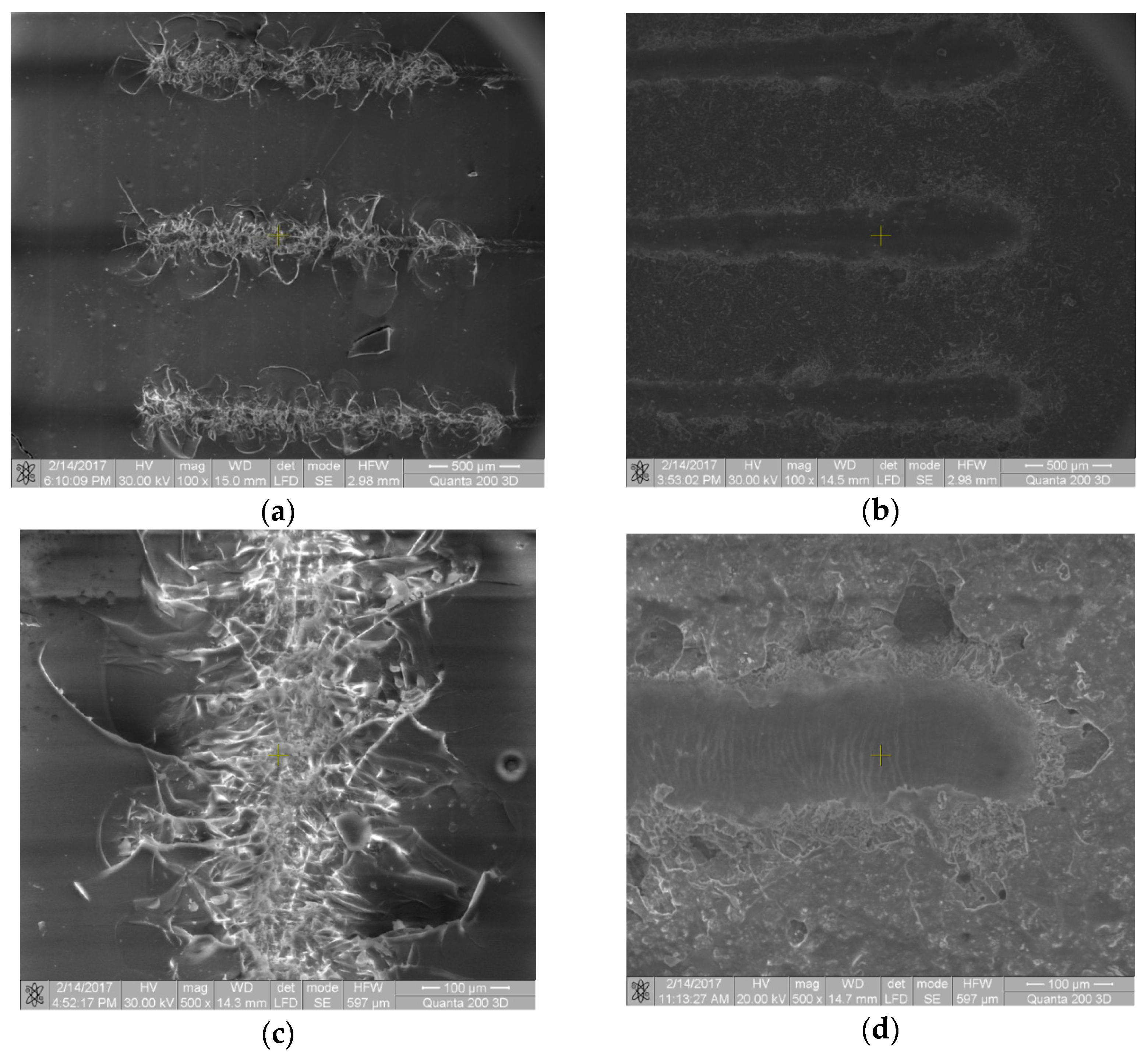
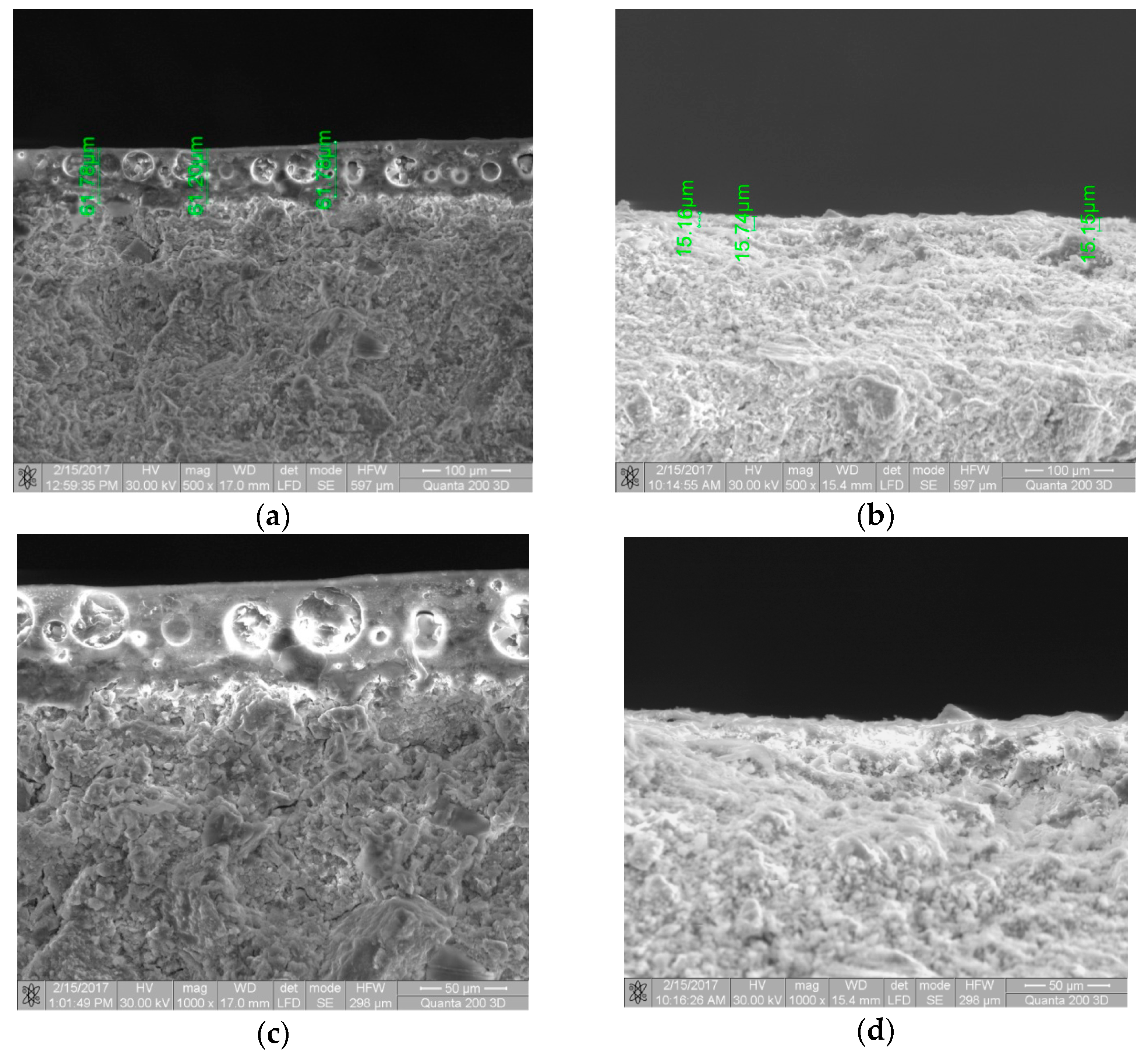
2.5. Scanning Electron Microscopy and X-ray Analysis

Scanning electron microscopy was performed with Quanta 200 3DDual-Beam (FEI, Brno, Czech Republic), secondary electrons, low vacuum 60 Pa, with large field detector (LFD), high voltage (HV) 30 kV and half field wide (HFW). The XRD measurements were performed on X’Pert PROMRD diffractometer (PANalytical, Almelo, The Netherlands). A measurable 2θ-range is from 10° to 90°. Data processing was done with X’PertData Collector, X’Pert High Score Plus and X’Pert Data Viewer. All experimental parameters are detailed in the paper [45].

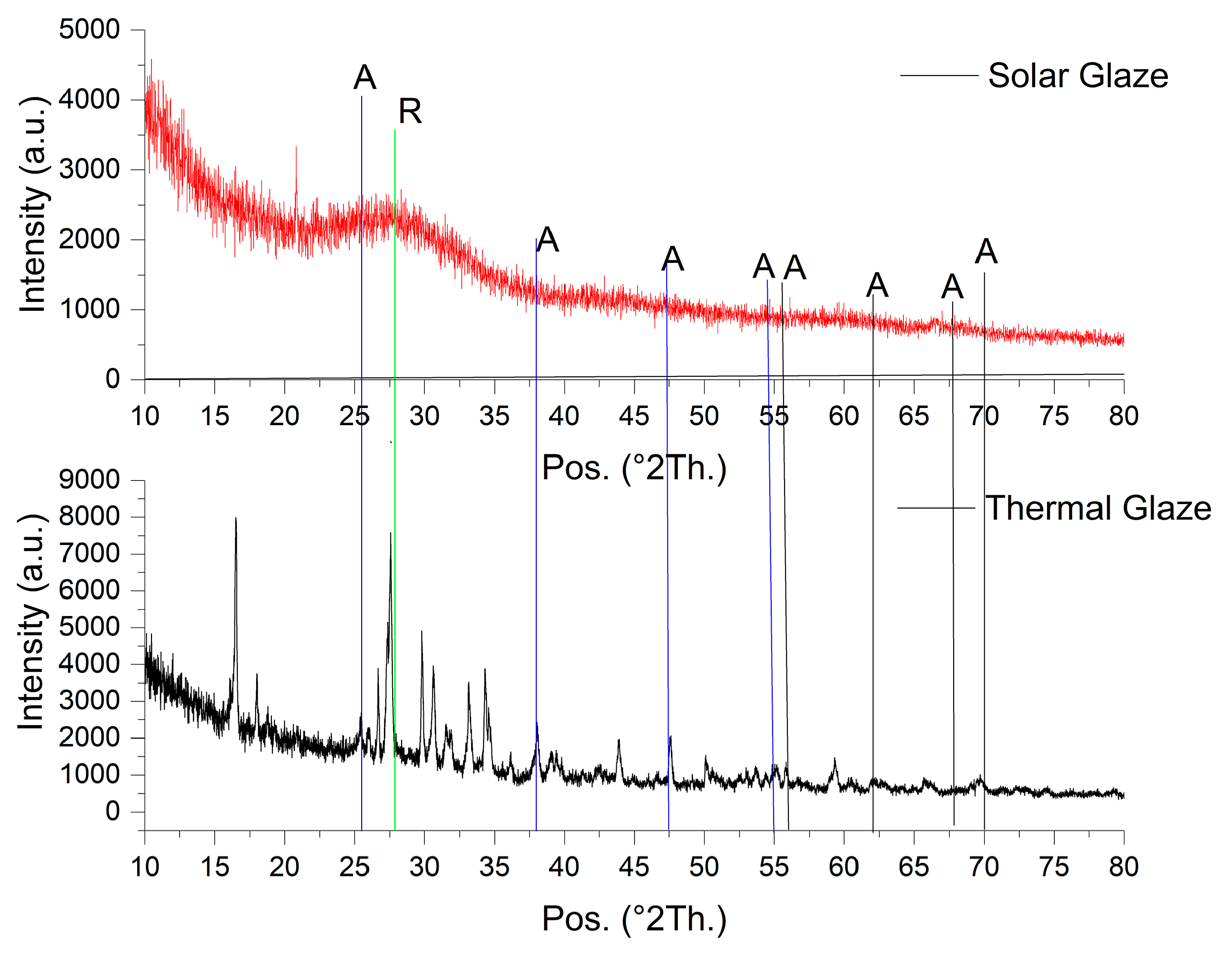
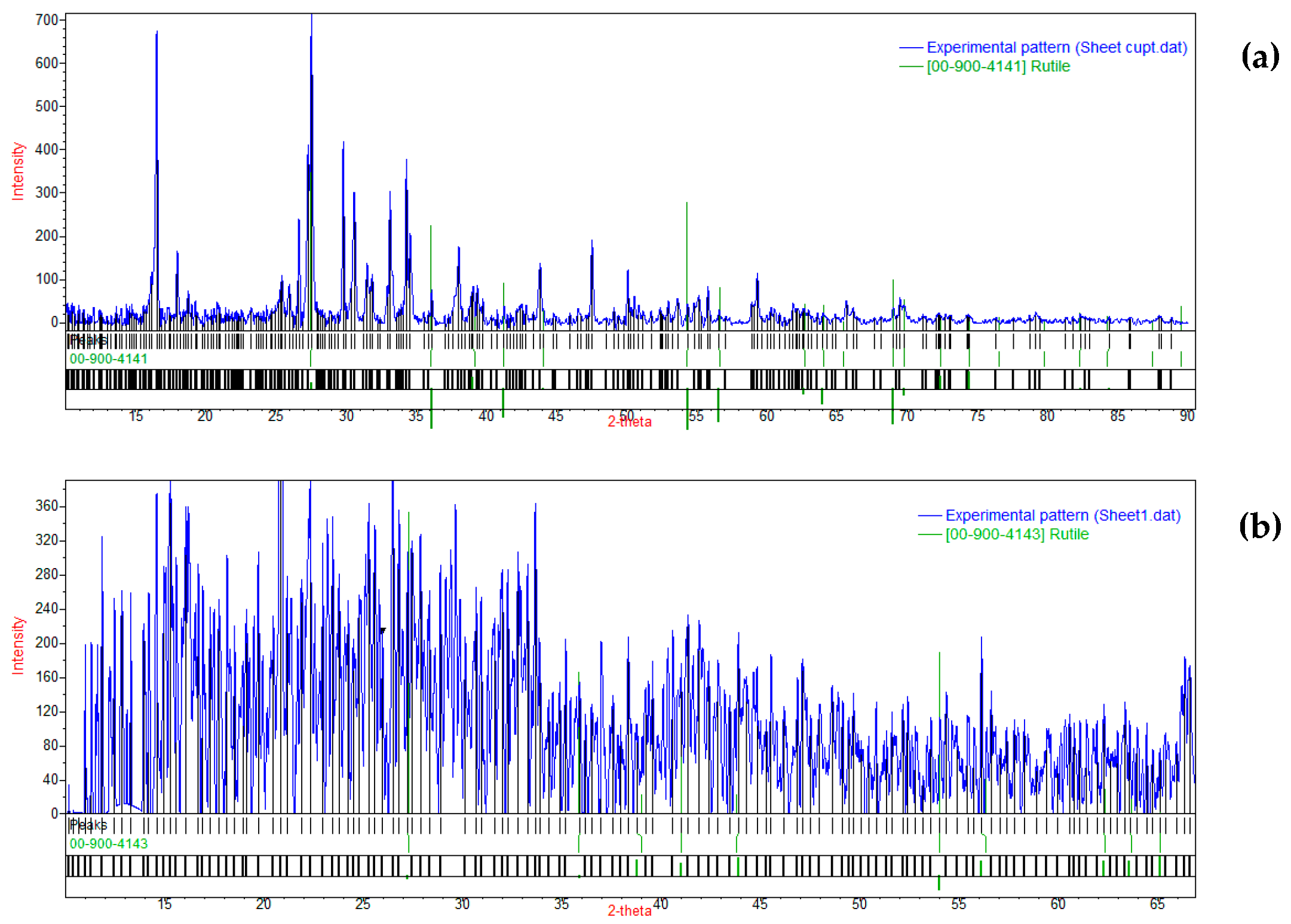
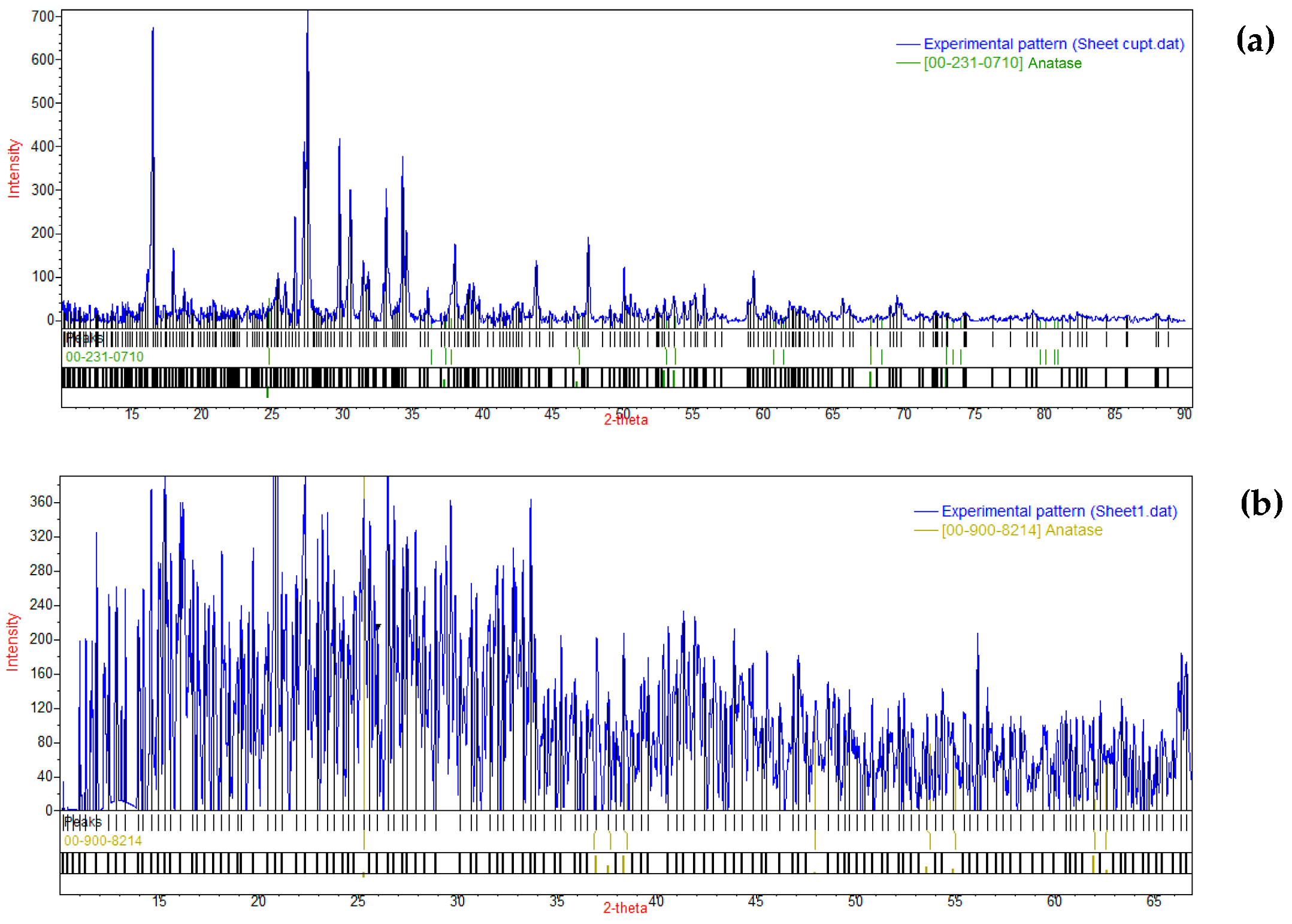
3. Results and Discussions

Glazed MDF composites were obtained by thermal treatment by using two different furnaces: classic electric and solar energy. The surface morphologies of the two sample types are illustrated in Figure 3a (concentrated solar heat treatment) and Figure 3b (conventional furnace heat treatment).
From Figure 3 it should be noted that SEM images of the concentrated solar-glazed sample (a,c) has a uniform glaze layer, glassy, transparent, with few apparent TiO2 particle agglomerations, implying their good dispersion. On the contrary, the glaze layer obtained by classic heating (b,d) shows a less transparent glaze, less glassy, with visible uniform dispersed TiO2 particle agglomerations. The difference in transparency could be ascribed to differences in glaze crystallization. For the conventional heat treatment, the crystallinity of the glaze is higher than in the concentrated solar energy heat treatment, where the conditions of obtaining an amorphous glaze are better met, i.e., higher cooling rates of the surface layer than in the case of electric furnace heat treating.
Differences in morphology could be explained also in conjunction with the cross-section SEM images of the glazed samples (Figure 4).
From Figure 4, it should be noted that the dramatic changes in glaze morphology when the concentrated solar technology were used by comparing those obtained by classical furnace.
Due to the very high rate of heating in the first step of the solar treatment, the enamel dispersant was very rapidly and bulkily vaporized, concomitantly with the enamel viscosity increase and the cross-linking of the silicate.
These simultaneous processes led to obtaining a very porous layer, with closed spherical pores with diameters up to 40 µm, and consequently to the increase of the layer thickness.
In the case of solar treatment, a glaze with approximately 61 µm thickness was obtained, comparatively to that obtained by electric furnace, when only approximately a 16 µm height glaze layer was measured.
The bubbles formation into the glaze mass could be explained, according to [48], considering the following gas sources: (i) evaporation of the volatile substances contained by the enamel dispersion such as water and organic solvents; (ii) release of the gas trapped in the pores of the support material (MDF) during melting of the glaze; (iii) release of the dissolved gas from the enamel dispersion during the heating process; (iv) release of the gaseous products obtained by additives degradation.
When using the concentrated solar furnace, a uniform glaze layer could be obtained only using a higher amount of glaze paste. When using a lower amount, this quantity is quickly removed from the surface during high-rate heating, due to the burst gases being removed. So, when a higher paste mass is used, the gases coming from the mentioned sources cannot be released from the melted glaze’s viscous mass, remaining trapped in the solid glaze layer, also increasing its thickness. It could be noted that the ratio of thickness increase is higher, about 3.8, for a ratio of enamel mass increase of 3.2. The glaze surface obtained is smooth and glassy. Moreover, a better radiative heat input in the concentrated solar heat-treated material could lead to a more efficient fusioning of the amorphous glaze on the surface of the material, rather than using convective heating in the case of electric furnace heat treatment.
In case of the classical electric furnace use, a uniform thinner glaze layer could be obtained. The lower temperature gradient will determine a lower rate of the gas release and of the glaze viscosity increase. The formed bubbles will reach the melt surface more easily, breaking them and determining a higher rough surface of the solid glaze layer.
These phenomena have also been confirmed in [43]. Thick solidified bubbled layers, with low surface roughness obtained due to the complete melting of the material under the high concentrated energy impact. Lower energy applied to ceramic tiles surface was insufficient for complete melting of the material, leading to a thin solidified layer with a higher roughness, due to the presence of large unmolten particles reaching the surface of solidified layer. High similarity between the mentioned study [43] and our results could be noted in terms of surface layer morphology.
The glaze transparency obtained by solar technology could be explained both by the complete melting of the glaze paste and by the apparently lower concentration of TiO2 particles, due to their distribution in a thicker glaze layer, and at the same time, by the very close refractive index that the glaze and bubble contain. The glaze obtained by electric furnace treatment is thinner and more compact.
XRD analysis of both obtained glazed MDF composites is presented in Figure 5.
The overall shape of the diffraction spectra may serve as an indicator for their structure. In the case of the electric furnace-glazed sample, the diffraction peaks are generally well resolved, their absolute intensity is high (between ~800 and 8000 a.u.), which could be indicative of a higher crystallinity than for the solar furnace-glazed sample. The latter has a broad, amorphous halo centered at ~27°, typical of silicate glasses [49], on which several peaks of lower intensity could be noted, generally indicating its predominant amorphous structure. A shift of the maximum toward the higher angles was reported by [49] with increasing alkali silica reaction times. From Figure 5, it could be similarly noted that the glaze obtained by solar technique shows a higher peak shift to 2θ = 27°, suggesting the formation of new species, that increases diversity in the silica structure bond distance distribution, with broader diffuse peaks in the XRD data. It was reported [49] that with higher reaction times, the average bond distance in the structure becomes shorter, possibly due to more O–H species connected to Si, determining a shift of the X-ray diffraction peaks toward higher angles.
Attribution of the main peak contributions for the two polymorphs of TiO2, anatase and rutile to the spectra from Figure 5, has been performed with the QualX software and the POW_COD SQLITE database [50]. The CIF cards no. 00-900-4141 (electric furnace-glazed sample) and 00-900-4143 (solar furnace-glazed sample) were used for rutile (Figure 6). For anatase (Figure 7), the CIF card no. 00-231-0710 corresponding to nanocrystalline anatase (electric furnace-glazed sample), respectively CIF card no. 00-900-8214 corresponding to anatase (solar furnace-glazed sample) were used.
For the solar furnace-glazed sample, ascribing the peaks was more difficult, due to the presence of the amorphous contribution. This contribution was removed using the QualX software, and the comparison with the rutile and anatase diffraction data cards yielded matches for the main peaks of anatase (such as 25.29°, 37.59°, 47.98°, 53.58°, 54.88°, 62.08°) and of rutile (27.30°, 35.91°,50.79°), both instances being marked with A or R on Figure 5.
The short time of enamel melting under the high intensity of solar radiation followed by rapid glaze solidification did not allow the components’ crystallization.
The scratch test could reveal other characteristics of the glazed MDF composites, such as adhesion of the glaze to the substrate, type of the glaze cohesion loss under critical loadings, differences between the elasticity of the glaze and substrate, and the recovery of materials after elastic deformation determined by the normal force compression. A comparison of these characteristics of glazed MDF composites, obtained by two different technologies, will allow us to conclude about the possibilities of replacing the classic thermal treatment with the solar energy-based one.
Figure 8 shows a remarkable distinction between the critical loads of the cohesion loss between glaze and substrate. Circular cracks were developed in the scratching direction and propagate from the glaze surface to the MDF composite substrate. A Hertzian cohesion loss could be noted (Lc1). The higher the normal loading force, the higher the share stress at the interface, due to the decrease of the contact area between the glaze and the substrate, denser and overlapping the circular cracks and the appearance of the layer chips on the glaze surface should be noted at Lc2. Penetration of the glaze and substrate reaching is marked by Lc3. In case of the glaze obtained in the electric furnace, the first two steps of the adhesion loss were difficult to separate, while the third one, Lc3, is very easy to note. Due to the differences between the coats’ thicknesses, the cracks propagation is different in glazes obtained by using the two mentioned technologies. While the glaze obtained in electric furnace led to a gross spallation of the coat at Lc3, in the case of solar obtained glaze, the cracks are mainly propagating into the glaze mass, showing a lateral development of many branches. The resulting parts mainly remained attached to the MDF surface.
The obtained results show that glazed MDF composites obtained by both technologies have a similar behaviour with that of the hard-brittle coatings on ceramics, reported by Li et al. [51]. Solar glaze seems to be more brittle and more adherent to the MDF surface than that obtained by clasical thermal treatment. Britleness and adherece increasing can be explained by the increasing of thickness and decreasing of cristalinity obtained in the solar furnace.
Figure 9 shows that the glazing of MDF composites with different amount of enamel and with different solar radiation intensity have a minor influence on the glaze scratch characteristics Lc1, Lc2 and Lc3, meaning the adhesion and cohesion forces developed in the MDF glazed materials.

4. Conclusions

Glazed MDF composites have been obtained by using solar energy. Some of the glaze properties were determined and compared to those obtained in the electric furnace. It could be noted that solar glazing imposes the use of higher paste amount to obtain a consistent and uniform glaze. As a result, the glaze thickness is higher by comparing to the classical treated samples. The thickness of the solar obtained glaze also increased due to a bubble formed during gases release and silicate cross linking. This led to a porous morphology of the glaze, with spherical closed pores. An increase of the glaze thickness determined that the repartition of TiO2 nano-particles aggregates in a higher volume, meaning an apparent decrease of their concentration. These aspects, as well as the complete melting of the glaze, due to the high energy used, led to a more transparent and glossier glaze obtained by solar treatment. Furthermore, the rapid sample heating led to a more amorphous, glassy, highly cohesive and adhesive glaze. The paste amount used, and the intensity of the solar flux (in the tested domain), seemed to influence, in a minor measure, the glaze scratch characteristics. The scratch resistance of the glaze obtained by solar energy is superior to that obtained by classic treatment. A higher rate of the solar glazing process, the lower cost of solar energy, the lower temperatures necessary for glaze formation that must avoid the anatase polymorph transformation to rutile and consequently the increase of the glaze photoactivity, low emission of pollutants in the atmosphere, all make solar glazing technology an attractive one. More studies have to be made to optimize the technological parameters in order to obtain a larger glazed surface of the MDF composite and to enlarge testing of the obtained materials. Taking into account the good photocatalytic activity and the increased water resistance observed in the case of glazed MDF obtained by heat treatment in the electric furnace [45], improving the features for the concentrated solar glazed sample are expected. The influence of glazing parameters on the photocatalytic properties of MDF cements will be detailed in a future study.

Author Contributions

Conceptualization, L.S.B. and S.P.; methodology, L.S.B., S.P., O.E. and H.O.; software, S.P.; validation, L.S.B., C.C. and S.P.; formal analysis, L.S.B., S.P., O.E. and H.O.; investigation, L.S.B., S.P., M.H.T., C.M. and B.I.; resources, L.S.B., O.E. and H.O.; data curation, L.S.B., S.P., M.H.T., C.M. and B.I.; writing—original draft preparation, L.S.B. and S.P.; writing—review and editing, L.S.B., S.P., C.C., M.H.T., C.M. and B.I.; visualization, S.P.; supervision, C.M. All authors have read and agreed to the published version of the manuscript.

Funding

This research was partially funded by FP7 Program/SFERA II, grant number 312642.

Institutional Review Board Statement

Not applicable.

Informed Consent Statement

Not applicable.

Data Availability Statement

The data presented in this study are available on request from the first author, with the permission of Transilvania University of Brasov.

Acknowledgments

Part of this work has been supported financially by European Solar Research Infrastructure for Concentrated Solar Power –Second Phase–SFERA ll; “Improvement of MDF cements properties through metallic oxide coating using solar energy. Acronym: SOL4COAT”, 2016. Contract no. CIEMAT PSA _EU 312642. The authors are also thankful to assoc. Nicanor Cimpoesu (Faculty of Materials Science and Engineering, Gheorghe Asachi Technical University of Iasi, Romania) for EDS analyses and to lecturer Daniel Cristea (Faculty of Materials Science and Engineering, Transilvania University of Brasov, Romania) for the scratch testing of composites coatings.

Conflicts of Interest

The authors declare no conflict of interest.

References

  1. Kabir, E.; Kumar, P.; Kumar, S.; Adelodun, A.D.A.; Kim, K.H. Solar energy: Potential and future prospects. Renew. Sustain. Energy Rev. 2018, 82, 894–900. [Google Scholar] [CrossRef]
  2. Farjana, S.H.; Huda, N.; Parvez Mahmud, M.A.; Saidur, R. Solar process heat in industrial systems–A global review. Renew. Sustain. Energy Rev. 2018, 82, 2270–2286. [Google Scholar] [CrossRef] [Green Version]
  3. Sharma, A.K.; Sharma, C.; Mullick, S.C.; Kandpal, T.C. Solar industrial process heating: A review. Renew. Sustain. Energy Rev. 2017, 78, 124–137. [Google Scholar] [CrossRef]
  4. Lédé, J. Solar thermochemica lconversion of biomass. Sol. Energy 1999, 65, 3–13. [Google Scholar] [CrossRef]
  5. Epstein, M.; Spiewak, I.; Funken, K.H.; Ortner, J. Review of the technology for solar gasification of carbonaceous materials. Am. Soc. Mech. Eng. Sol. Eng. 1994, 26, 79–97. [Google Scholar]
  6. Puig-Arnavat, M.; Tora, E.A.; Bruno, J.C.; Coronas, A. State of the art on reactor designs for solar gasification of carbonaceous feedstock. Sol. Energy 2013, 97, 67–84. [Google Scholar] [CrossRef]
  7. Nzihou, A.; Flamant, G.; Stanmore, B. Synthetic fuels from biomass using concentrated solar energy-A review. Energy 2012, 42, 121–131. [Google Scholar] [CrossRef] [Green Version]
  8. Yadav, D.; Banerjee, R. A review of solar thermochemical processes. Renew. Sustain. Energy Rev. 2016, 54, 497–532. [Google Scholar] [CrossRef]
  9. Herranz, G.; Romero, A.; Castro, V.; Rodriguez, G.P. Development of high speed steel sintered using concentrated solar energy. J. Mater. Process. Technol. 2013, 213, 2065–2073. [Google Scholar] [CrossRef]
  10. Herranz, G.; Romero, A.; Castro, V.; Rodriguez, G.P. Processing of AISI M2 high speed steel reinforced with vanadium carbide by solar sintering. Mater. Des. 2014, 54, 934–946. [Google Scholar] [CrossRef]
  11. Reyo-Prats, R.; Plaza, A.C.; Faugeroux, O.; Claudet, B.; Soum-Glaude, A.; Hildebrandt, C.; Binyamin, Y.; Aguero, A.; Meißner, T. Accelerated aging of absorber coatings for CSP receivers under real high solar flux. Sol. Energy Mater. Sol. Cells 2019, 193, 92–100. [Google Scholar] [CrossRef]
  12. Cambronero, L.E.G.; Canadas, I.; Ruiz-Román, J.M.; Cisneros, M.; Corpas Iglesias, F.A. Weld structure of joined aluminium foams with concentrated solar energy. J. Mater. Process. Technol. 2014, 214, 2637–2643. [Google Scholar] [CrossRef]
  13. Haferkamp, H.; Bunte, J.; Herzog, D.; Ostendorf, A. Laser based welding of cellular aluminium. Sci. Technol. Weld. Join. 2004, 9, 65–71. [Google Scholar] [CrossRef]
  14. Pantelis, D.I.; Karakizis, P.N.; Kazasidis, M.E.; Karalis, D.G.; Rodrıguez, J. Experimental and numerical investigation of AA6082-T6 thin plates welding using Concentrated Solar Energy (CSE). Sol. Energy Mater. Sol. Cells 2017, 171, 187–196. [Google Scholar] [CrossRef]
  15. Romero, A.; García, I.; Arenas, M.A.; López, V.; Vázquez, A. Ti6Al4V titanium alloy welded using concentrated solar energy. J. Mater. Process. Technol. 2015, 223, 284–291. [Google Scholar] [CrossRef]
  16. Flamanta, G.; Ferrierea, A.; Laplazeb, D.; Montya, C. Solar processing of materials: Opportunities and new frontiers. Sol. Energy 1999, 66, 117–132. [Google Scholar] [CrossRef]
  17. Carle, J.E.; Andreasen, J.W.; Jørgensen, M.; Krebs, F.C. Low band gap polymers based on 1,4-dialkoxybenzene, thiophene, bithiophene donors and the benzothiadiazole acceptor. Sol. Energy Mater. Sol. Cells 2010, 94, 774–780. [Google Scholar] [CrossRef]
  18. Helgesen, M.; Krebs, F.C. Photovoltaic performance of polymers based on dithienylthienopyrazines bearing thermocleavable benzoate esters. Macro Mol. 2010, 43, 1253–1260. [Google Scholar] [CrossRef]
  19. Tromholt, T.; Manceau, M.; Helgesen, M.; Carle, J.E.; Krebs, F.C. Degradation of semiconducting polymers by concentrated sunlight. Sol. Energy Mater. Sol. Cells 2011, 95, 1308–1314. [Google Scholar] [CrossRef]
  20. Boubault, A.; Claudet, B.; Faugeroux, O.; Olalde, G. Aging of solar absorber materials under highly concentrated solar fluxes. Sol. Energy Mater. Sol. Cells 2014, 123, 211–219. [Google Scholar] [CrossRef]
  21. Rodriguez-Sanchez, M.R.; Santana, D.; Olalde, G. Experimental study of honeycomb SiCSi under highly concentrated solar flux. Evolution of its thermo-radiative properties. Sol. Energy Mater. Sol. Cells 2016, 155, 253–263. [Google Scholar] [CrossRef]
  22. Ceballos-Mendivil, L.G.; Cabanillas-López, R.E.; Tánori-Córdova, J.C.; Murrieta-Yescas, R.; Pérez-Rábago, C.A.; Villafán-Vidales, H.I.; Arancibia-Bulnes, C.A.; Estrada, C.A. Synthesis of silicon carbide using concentrated solar energy. Sol. Energy 2015, 116, 238–246. [Google Scholar] [CrossRef]
  23. Sierra, C.; Vazquez, A.J. NiAl coatings on carbon steel by self-propagating high-temperature synthesis assisted with concentrated solar energy: Mass influence on adherence and porosity. Sol. Energy Mater. Sol. Cells 2005, 86, 33–42. [Google Scholar] [CrossRef]
  24. Plaza, D.M.; Cañadas Martinez, I.; Gasch, G.M.; Sufrategui, F.T.; García, J.R. A case study of the feasibility of using solar concentrating technologies for manufacturing ceramics. J. Clean. Prod. 2015, 87, 977–991. [Google Scholar] [CrossRef]
  25. Roman, R.; Canadas, I.; Rodrıguez, J.; Hernandez, M.T.; Gonzalez, M. Solar sintering of alumina ceramics: Microstructural development. Sol. Energy 2008, 82, 893–902. [Google Scholar] [CrossRef]
  26. Apostol, I.; Rodríguez, J.; Cañadas, I.; Galindo, J.; Mendez, S.L.; Abreu Martins, P.L.; Cunha, L. Concentrated solar energy used for sintering magnesium titanates for electronic applications. Appl. Surf. Sci. 2018, 438, 594–665. [Google Scholar]
  27. Rashidi, S.; Tamayol, A.; Valipour, M.S.; Shokri, N. Fluid flow and forced convection heat transfer around a solid cylinder wrapped with a porous ring, a solid cylinder wrapped with a porous ring. Int. J. Heat Mass Transf. 2013, 63, 91–100. [Google Scholar] [CrossRef]
  28. Rashidi, S.; Bovand, M.; Pop, I.; Valipour, M.S. Numerical simulation of forced convective heat transfer past a square diamond-shaped porous cylinder. Transp. Porous Media 2014, 102, 207–225. [Google Scholar] [CrossRef]
  29. Rashidi, S.; Esfahani, J.A.; Rashidi, A. A review on the applications of porous materials in solar energy systems. Renew. Sustain. Energy Rev. 2017, 73, 1198–1210. [Google Scholar] [CrossRef]
  30. Lalau, Y.; Faugeroux, O.; Guillot, E.; Andre, D.; Huger, M.; Proust, A.; Chotard, T.; Claudet, B. Impact: A novel device for in-situ thermo-mechanical investigation of materials under concentrated sunlight. Sol. Energy Mater. Sol. Cells 2017, 172, 59–65. [Google Scholar] [CrossRef]
  31. Patachia, S.; Moise, G.; Ozkul, M.H.; Ekincioglu, O. Characterization of ecological macro defect free (MDF) cements by infrared spectrometry. Environ. Eng. Manag. J. 2011, 10, 237–240. [Google Scholar] [CrossRef]
  32. Patachia, S.; Moise, G.; Ozkul, M.H.; Ekincioglu, O.; Croitoru, C. Ecological polymer used for macro-defect-free cements (MDF) production. Environ. Eng. Manag. J. 2009, 8, 679–684. [Google Scholar] [CrossRef]
  33. Ekincioglu, O.; Ozkul, M.H.; Patachia, S.; Moise, G. Effect of TiO2 Addition on the Properties of Macro Defect Free Cement-Polymer Composites. Restor. Build. Monum. 2013, 19, 125–134. [Google Scholar] [CrossRef]
  34. Patachia, S.; Moise, G.; Ozkul, M.H.; Ekincioglu, O. Influence of the self cross linkable polymers on the properties of the macro defect free (MDF) cements. Bull. Transilv. Univ. Bras. 2009, 2, 181–186. [Google Scholar]
  35. Patachia, S.; Moise, G.; Ozkul, M.H.; Ekincioglu, O.; Croitoru, C. Influence of the Obtaining Technology on the Macro Defect Free Cements Characteristics. Pollack Period. 2009, 4, 75–82. [Google Scholar] [CrossRef]
  36. Patachia, S.; Moise, G.; Ozkul, M.H.; Ekincioglu, O.; Croitoru, C. Morphological Characterization of High Alumina Cement Based Macro Defect Free Cements. Bull. Transilv. Univ. Bras. 2008, 1, 251–254. [Google Scholar]
  37. Ekincioğlu, Ö.; Özkul, M.H.; Struble, L.J.; Patachia, S. State of the art of macro-defect-free composites. J. Mater. Sci. 2018, 53, 10595–10616. [Google Scholar] [CrossRef]
  38. Rasteiro, M.G.; Gassman, T.; Santos, R.; Antunes, E. Crystalline phase characterization of glass-ceramic glazes. Ceram. Int. 2007, 33, 345–354. [Google Scholar] [CrossRef] [Green Version]
  39. Sheikhattar, M.; Attar, H.; Sharafi, S.; Carty, W.M. Influence of surface crystallinity on the surface roughness of different ceramic glazes. Mater. Charact. 2016, 118, 570–574. [Google Scholar] [CrossRef]
  40. Da Silva, A.L.; Muche, N.F.D.; Dey, M.; Hotza, D.; Castro, H.R.R. Photocatalytic Nb2O5-doped TiO2 nanoparticles for glazed ceramic tiles. Ceram. Int. 2016, 42, 5113–5122. [Google Scholar] [CrossRef] [Green Version]
  41. Teixeira, M.; Bernardin, A.M. Development of TiO2 white glazes for ceramic tiles. Dyes Pigm. 2009, 80, 292–296. [Google Scholar] [CrossRef]
  42. Romero, M.; Robla, J.I.; Padilla, I.; García-Hierro, J.; López-Delgado, A. Eco-efficient melting of glass frits by concentrated solar energy. Sol. Energy 2018, 174, 321–327. [Google Scholar] [CrossRef]
  43. Rey-Garcia, F.; Gutiérrez-Morac, F.; Borrela, C.J.; Estepaa, L.C.; Angurela, L.A. Microstructural characterization and tribological behavior of laser furnace processed ceramic tiles. Ceram. Int. 2018, 44, 6997–7005. [Google Scholar] [CrossRef] [Green Version]
  44. Izadi, A.; Heidari, B.; Kasrai, S.; Soltanian, A.; Raissi, S. Comparison of surface roughness between CO2 laser and typical glazing on two types of porcelain vita and ivoclar. Biosci. Biotechnol. Res. Commun. 2017, 10, 529–535. [Google Scholar] [CrossRef]
  45. Baltes, L.; Patachia, S.; Tierean, M.; Ekincioglu, O.; Ozkul, H.M. Photoactive glazed polymer-cement composite. Appl. Surf. Sci. 2018, 438, 84–95. [Google Scholar] [CrossRef]
  46. Ekincioglu, O.; Ozkul, M.H.; Struble, L.J.; Patachia, S. Optimization of material characteristics of macro-defect free cement. Cem. Concr. Compos. 2012, 34, 556–565. [Google Scholar] [CrossRef]
  47. Ekincioglu, O.; Ozkul, M.H.; Ohama, Y.; Patachia, S.; Moise, G. Effect of epoxy resin addition on the moisture sensitivity of macro defect free polymer-cement composites. Key Eng. Mater. 2011, 466, 65–72. [Google Scholar] [CrossRef]
  48. Pradell, T.; Molera, J.; Salvadó, N.; Labrador, A. Synchrotron Radiation Micro-XRD in the Study of Glaze Technology. Appl. Phys. A 2010, 99, 407–417. [Google Scholar] [CrossRef]
  49. Altomare, A.; Corriero, N.; Cuocci, C.; Falcicchio, A.; Moliterni, A.; Rizzi, R. QUALX2.0: A qualitative phase analysis software using the freely available database POW-COD. J. Appl. Crystallogr. 2015, 48, 598–603. [Google Scholar] [CrossRef]
  50. Zhang, G.; Xu, Y.; Xu, D.; Wang, D.; Xue, Y.; Su, W. Pressure-induced crystallization of amorphous SiO2 with silicon–hydroxy group and the quick synthesis of coesite under lower temperature. High Press. Res. 2008, 28, 641–650. [Google Scholar] [CrossRef]
  51. Li, K.; Bao, Y.; Wan, D.; Huo, Y.; Wu, J. Evaluating adhesion of ceramic coatings by scratch testing. Key Eng. Mater. 2012, 512–515, 959–964. [Google Scholar] [CrossRef]
Figure 1. The work area in the solar furnace: (a) general setup of the concentrating solar treatment installation; (b) the parabolic concentrating solar mirror; (c) sample support; (d) photographic image through a glass filter of the solar glazing process.
Coatings 11 00350 g001
Figure 2. Thermal regime for obtaining glazed MDF composites by using classic electric heating (□) and solar energy (■).
Coatings 11 00350 g002
Figure 3. SEM images of samples obtained by concentrated solar energy glazing (a,c) and by electric furnace (b,d), after scratch tests performed at different magnifications.
Coatings 11 00350 g003
Figure 4. Cross-section SEM for solar glazed MDF composites (a,c) and conventional thermal treatment (b,d) at different magnifications (magnification scale in the picture).
Coatings 11 00350 g004
Figure 5. XRD spectra and setup for MDF composites glazed by using solar and electric thermal energy.
Coatings 11 00350 g005
Figure 6. Peaks ascribing for the rutile polymorphs: electric furnace-glazed sample-rutile (a) and solar furnace-glazed sample-rutile (b).
Coatings 11 00350 g006
Figure 7. Peaks ascribing for the anatase polymorphs: electric furnace-glazed sample-anatase (a) and solar furnace-glazed sample-anatase (b).
Coatings 11 00350 g007
Figure 8. Optical microscopy images of the scratch test sample for glazed MDF composites obtained by solar energy.
Coatings 11 00350 g008
Figure 9. Comparison between Lc1, Lc2 and Lc3 values determined for samples obtained at different solar radiation energy and by using different amounts of enamel.
Coatings 11 00350 g009
Publisher’s Note: MDPI stays neutral with regard to jurisdictional claims in published maps and institutional affiliations.

