Article

Kinetics of the Boride Layers Obtained on AISI 1018 Steel by Considering the Amount of Matter Involved

by
Pablo A. Ruiz-Trabolsi
1,
Julio Cesar Velázquez
2,*,
Carlos Orozco-Álvarez
1,
Rafael Carrera-Espinoza
3,
Jorge A. Yescas-Hernández
3,
Noé Eliseo González-Arévalo
4 and
Enrique Hernández-Sánchez
1,*
1
Departamento de Bioingeniería, Instituto Politécnico Nacional, UPIBI, Avenida Acueducto s/n Barrio La Laguna Ticomán, México City 07340, Mexico
2
Departamento de Ingeniería Química Industrial, Instituto Politécnico Nacional, ESIQIE, UPALM Edif. 7, Zacatenco, México City 07738, Mexico
3
Departamento de Ingeniería Industrial y Mecánica, Universidad de las Américas Puebla, Ex hacienda Santa Catarina Mártir s/n, San Andrés Cholula Puebla 72810, Mexico
4
Departamento de Metalurgia y Materiales, ESIQIE, Instituto Politécnico Nacional, UPALM Edif. 7, Zacatenco, México City 07738, Mexico
*
Authors to whom correspondence should be addressed.
Coatings 2021, 11(2), 259; https://doi.org/10.3390/coatings11020259
Submission received: 21 January 2021 / Revised: 10 February 2021 / Accepted: 17 February 2021 / Published: 23 February 2021

Abstract

:
Boride layers are typically used to combat the wear and corrosion of metals. For this reason, to improve our knowledge of the boriding process, this research studied the effect of the size of the treated material on the kinetics of the growth of the boride layers obtained during a solid diffusion process. The purpose was to elucidate how the layers’ growth kinetics could be affected by the size of the samples since, as the amount of matter increases, the amount of energy necessary to make the process occur also increases. Furthermore, the level of activation energy seems to change as a function of the sample size, although it is considered an intrinsic parameter of each material. Six cylindrical samples with different diameters were exposed to the boriding process for three different exposure times (1.5, 3, and 5 h). The treatment temperatures used were 900, 950, and 1000 °C for each size and duration of treatment. The results show that the layer thickness increased not only as a function of the treatment conditions but also as a function of the sample diameter. The influence of the sample size on the growth kinetics of the boride layers is clear, because the growth rate increased even though the treatment conditions (time and temperature) remained constant.

1. Introduction

Boriding is one of the newest processes used to modify the surface properties of metallic materials. Boriding is the name for the diffusion of boron into a specific substrate (it can be almost any metal). Diffusion is a physical process that needs an available ion present in an adequate concentration for a period of time at a particular temperature [1]. The conditions are usually related to the crystal lattice of the substrate and the ion size. After the quantity of the diffused ion achieves the solubility limit, boron begins to form compounds with the constituent elements of the metal or alloy [1,2,3]. These metal borides tend to form complex compounds that increase the hardness of the surface. The resulting layer that is created on the substrate can mainly be characterized by its hardness and depth [1,2,3,4]. These two characteristics strengthen the surface, making it resistant to wear and corrosion. Industrially, boriding is applied for the formation of the bearing components of jet engines, turbine nozzles, valve components, instrumentation components, pump components, bushings, spray nozzles, chopping components in agricultural equipment, grooved drums, filtering screens, and rolls for rotogravure printing machines [5].
On the other hand, the required thickness of the layers depends on their industrial application. Thus, thin coatings (15 to 20 µm) are used against adhesive wear (stamping dies, extrusion tools, and so), while for erosion process applications, relatively thick layers (50 to 250 µm), which are generally formed on low-alloy steels, are recommended. In the case of high-alloy steels, the optimal layer thickness is between 25 and 75 µm [6].
The most usual method applied is pack boriding because it is easier to carry out than others [1,2,3]. In the pack-boriding process, boron is typically supplied from boron carbide (B4C), an activator to deposit atomic boron at the metal’s surface. The process implies the embedding of a sample in the powder mixture and sealing them in a metallic vessel. The vessel is then heated up to a proven temperature for the necessary period of time based on the results expected [7]. Through boron transmission into steel alloys, iron borides with a single-phase Fe2B (containing approximately 8.83 wt.% B) or a biphasic layer of FeB/Fe2B (with a FeB phase containing approximately 16.23 wt.% B) are expected [8]. Different characteristics, such as the substrate’s chemical composition, the boron potential, the temperature and the treatment time determine the resulting single- or double-phase layer. On the other hand, the boride layer thickness is determined by the aforementioned conditions [9]. In industry, layers with a single-phase Fe2B is preferred instead of a double-phase layer FeB/Fe2B, because the Fe2B layer is less brittle than FeB. Also, when a single layer (Fe2B) is achieved, it is possible to apply subsequent heat treatments to the substrate without affecting the layer properties of the layer [7]. For that reason, AISI (American Iron and Steel Institute) 1018 steel was selected to realize this work due to the single-phase layer (Fe2B) that can be expected when a low-carbon steel is exposed to boriding.
The activation energy necessary for the mobility of boron during the process has traditionally been estimated by an Arrhenius expression that considers the different temperatures of treatment and the growth rate of the layers (K) during the process [9,10]. On the other hand, the activation energy represents the amount of energy that has to be invested during the process to make the boron atoms move into the interstitial sites inside the metallic matrix in J·mol–1. Several researchers have reported values of activation energy that differ between the type of treated material [10,11,12,13]. The values reported are close but not the same, even for the same material. These small differences in activation energy values can be attributed to the amount of matter involved during the process, since the size of the samples also necessitates the involvement of greater or lesser quantities of boron atoms.
The purpose of this work was to elucidate how the thickness of the generated layers is influenced by the size of the samples and how it is possible to save energy by knowing the activation energy required during the boriding process for each material.
In that sense, the energy necessary for boron diffusion will depend on the amount of matter involved during the process (size of the samples).
One of the scientific contributions of this research work was to find an empirical model that represents boride layer growth in a simpler way, thus facilitating the analysis of the influences of the variables involved (temperature, amount of matter, time) and determining which variable exerts the greatest influence in order to optimize the boriding process.
The paper is divided into the following sections:
  • Experimental procedure: information about the cylindrical samples, materials used, heat treatment, and characterization techniques and a brief description of the growth kinetics is provided.
  • Results and discussion: microstructure studies and layer characterization are presented. Likewise, a discussion about the kinetics of boride layer growth and activation energy is given. Finally, in this section, the use of non-linear regression analysis is detailed in order to divulge the advantages of this statistical technique.
  • Conclusions: details about the importance of studying the amount of matter, temperature, and exposure time in the boride layer growth study are given.

2. Experimental Procedure

2.1. Boriding Treatment

Cylindrical samples of AISI 1018 (Carpenter steels, México City, México) with diameters of 1.85, 2.38, 6.32, 7.95, 11.12, and 12.70 mm and lengths of 7 mm were prepared using a traditional metallographic technique consisting of sequentially sanding the samples with 80 to 600 mesh silicon carbide (SiC) grit paper. During the sanding process, it was necessary to add distilled water to avoid excessive heating which could affect the microstructure of the samples’ surfaces. The chemical composition of the samples is described in Table 1.
After the metallographic process was complete, samples were cleaned in an ultrasonic bath for 5 min in ethanol in order to eliminate impurities. The boriding process was carried out on a solid medium by embedding the samples in a square case (AISI 304) containing a fresh B4C, Hef–Durferrit powder mixture. Samples were placed separately 15 mm from each other as well as being 15 mm away from each side of the container to avoid oxidation, as shown in Figure 1.
The boriding process was carried out for three different periods of time (1.5, 3, and 5 h) at temperatures of 900, 950, and 1000 °C for each period in the absence of an inert atmosphere. After boriding, samples were cooled to room temperature inside the furnace to avoid thermal crash and subsequent fracture of the layers. Samples were then embedded in Bakelite and prepared by standard metallographic techniques for microscopic examination.

2.2. Characterization

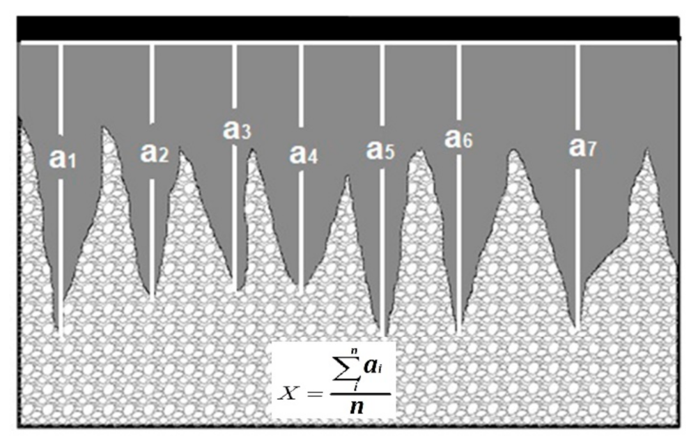
The thickness of the boride layers was measured with specialized software through the digitalization of optical images with the aid of a GX-51 optical microscope (Olympus, Center Valley, PA, USA). The contours of the samples were measured in order to establish a mean value for the layer thickness, as shown in Figure 2.
The nature of the layers was established by X-ray diffraction (XRD) and Raman spectroscopy with the aid of a D8 FOCUS diffractometer using Cu–Kα radiation at a wavelength of 1.5418 Å (Bruker, Billerica, MA, USA) and a Labram (model HR-800, Horiba Jobin Yvon, HORIBA instruments, Irvine, CA, USA).

2.3. Kinetics of Growth

It is well known that the kinetics of boride layer growth is controlled by boron diffusion; therefore, the growth of layers occurs as a consequence of boron diffusion perpendicular to the surfaces of the samples [14]. On the other hand, considering that, for a given distance (x), in any period of treatment (t), the relation between the boron concentration and the diffusion coefficient tends to be constant, the growth of the boride layers can be described as:
x 2 = K t
which means that the boride layers’ growth obeys a parabolic law [14].
x is the thickness of the boride layers (m), K is the constant of parabolic growth (m2/s), which is related to the coefficient of diffusion of the boride layers, in the particular case of low-carbon steels such as AISI 1018 [10], and t is the treatment time (s).
As can be seen from Equation (1), K can be estimated from the slopes of the square of the thickness (x2) versus treatment time graphs. When the square of the layer thickness is graphed against the treatment time, the slope of the curve increases as the treatment time increases at a constant temperature and, also, when the temperature increases, the slope of the graph increases, so K has Arrhenius-type behavior, as follows:
K = K 0 exp Q / R T
where K0 is a pre-exponential constant that reflects the frequency of boron atom collisions with the substrate. K0 can be estimated by the intersection of the ordinates with the axis. (Q) is the activation energy (J·mol−1) required to make the reaction occur, T is the absolute temperature (Kelvin), and R is the universal constant of ideal gases (8.3144 J·mol−1·K−1). As mentioned previously, the activation energy was estimated for each sample size, considering the estimated K and K0 for each sample size.

2.4. Activation Energy and Invested Energy Calculation

The activation energy is responsible for the movement of boron into the layers [15]. It is considered intrinsic to the material and can be estimated by plotting Equation (2) in logarithm form, as follows:
ln K i = ln K 0 i Q i R 1 T
The energy invested during the process for each sample size (Ei) can be estimated as a function of the size of the samples by the calculation of the total amount of matter involved during the process (N) in moles, as follows:
Q i = E i N i   J mol
E i = ( Q i )   ( N i )   J   mol mol
The number of moles (Ni) was calculated as a function of the sample size and the molecular weight (MW) of iron (Equation (6)):
M W = m a s s N g m o l
The mass of the samples was obtained from the steel density, which relates the mass of the samples with their volume. Therefore, the number of moles can be obtained as:
N i = V i ρ M W
Finally, by substituting (7) into (5),
E i = Q i   ρ M W   V i
Equation (8) means that the energy invested during the process is directly related to the sample size, represented by its volume.
Ni is the number of moles involved during the process for each sample size (mol); Ki, K0i, and Qi, have the same meaning as mentioned before, but for each sample size; Vi is the volume of the samples in cm3; Ei is the energy invested in layer growth for each sample size (J); r is the density of the treated material (AISI 1018 steel) (7.85 gcm−3); and MW is the molecular weight of the treated material (55.845 g·mol−1).
The real activation energy (E) for AISI 1018 steel for the established conditions was estimated by the slope of the Ei vs. V curve from Equation (8).
The volumes of the samples were established for different diameters and retaining a constant length of 7 mm. The main reason for this was to calculate Ei as a function of the volume of the samples so that all size and shape possibilities for the treated materials were covered by the model proposed in Equation (8), as the boriding theory states that all materials have to be at the same temperature before starting the diffusion process [7].

2.5. Regression Analysis

On the other hand, empirical models are frequently employed to describe some material engineering processes [16,17,18,19,20]. These empirical models are built through regression analysis. It is well known that layer growth has a parabolic form (see Equation (1)) described by a power law [16]. In this study, the power law used to determine the layer thickness growth was as follows:
x = κ   t η
In the above equation, κ is the scaling coefficient and η is the power coefficient. Using this equation, it is feasible to investigate the dependence of κ and η on the temperature and the amount of substance (number of moles). In this study, the scaling coefficient was a function of the temperature and the exponent parameter was determined by the number of moles. Therefore, the regression formula for the estimated layer thickness growth was proposed as:
x = ( k 0 T α + k 1 )   t ( η 0 + η 1 N β )
Where κi, ηi, α, and β are the regression coefficients for the predictor, while N is the number of moles in the system, and T is the temperature.

3. Results and Discussion

3.1. Microstructure

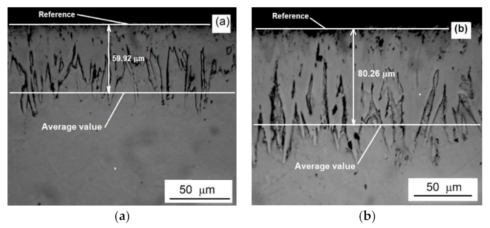
Optical examination of the cross sections of borided samples revealed the presence of three zones (Figure 3). The outermost was assumed to be a biphasic layer containing FeB/Fe2B compounds with a saw-toothed morphology, which is the typical morphology of the borided low carbon steels [3,9]. The second one was a diffusion zone, and the substrate (third zone) was not affected by the diffusion process.
The saw-toothed microstructure of the boride layer on low-carbon steel is a result of the diffusion process, which causes growth of a strongly anisotropic nature, in which the growth of the Fe2B layer is preferentially in the (001) crystallographic direction [21]. Several studies have established that the grain orientation of boride layers on polycrystalline substrates seems to be mainly controlled by growth kinetics rather than by the grain orientation of the substrate material [22,23].
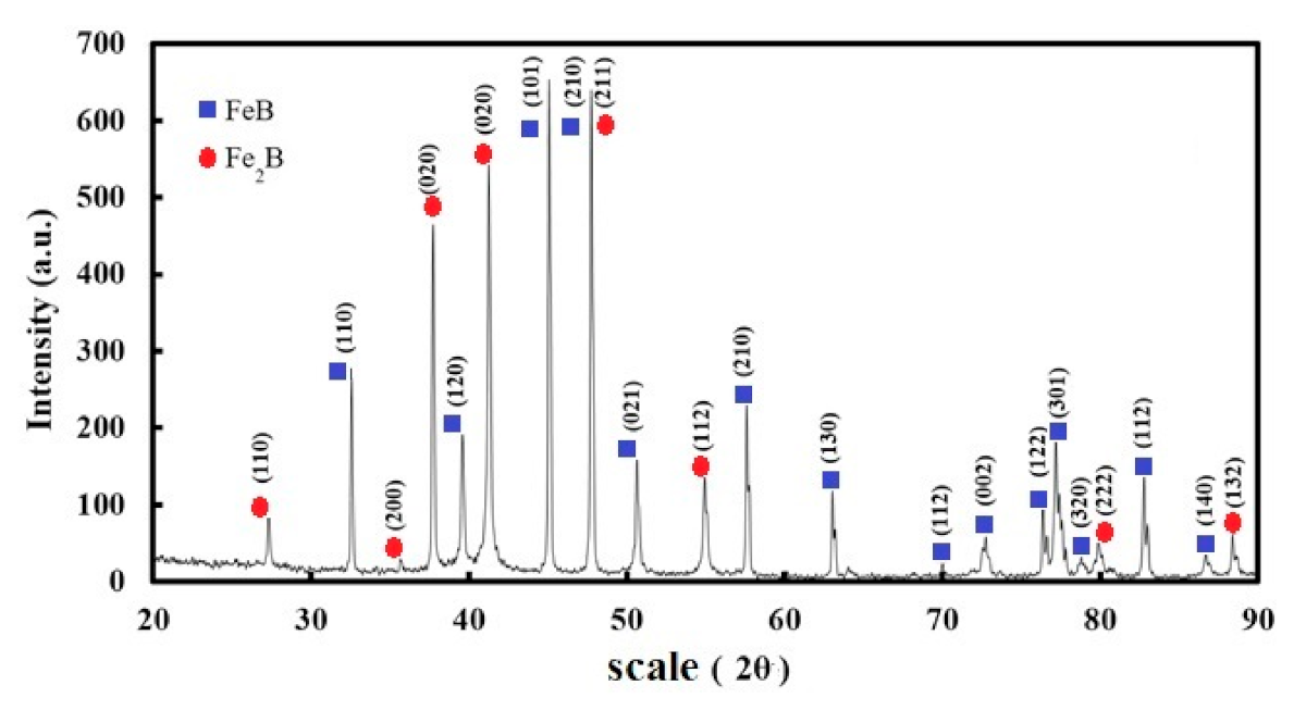
The XRD pattern presented in Figure 4 corresponds to the sample with a diameter of 11.12 mm that was exposed to treatment at 950 °C for 5 h. In Figure 4, it is possible to observe that, after the treatment, the sample was totally covered by a mainly biphasic layer of FeB/Fe2B with orthorhombic and tetragonal crystalline structures, respectively, in the crystallographic direction (001), which is the preferential direction for boron diffusion [7].
The XRD patterns were compared with data cards 00-036-1332 and 00-032-0463, which represent the patterns of the Fe2B and FeB phases, respectively. The strongest reflections were found at (101), (2θ = 45.02°) for FeB, (210) and (211), (2θ = 48°) for FeB/Fe2B, as well as at (110) and (112) to a minor extent for the Fe2B layer. These results indicate that the layer formed at the surface of the 11.12 mm diameter sample under the mentioned conditions was a biphasic layer composed mainly of FeB/Fe2B. This is as expected for low-carbon steel exposed to boriding.
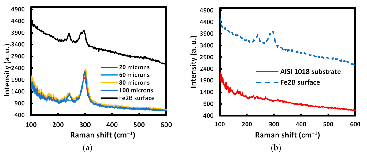
Raman spectroscopy assays were conducted along the boride layer, as shown in Figure 5. In addition, the surface and steel substrate were analyzed to corroborate the presence of the boride phases.
Figure 5a shows the patterns achieved along the cross section of the boride layer and also at the surface of it. As can be observed, two-well defined bands (242.95 and 297.95 cm−1) were deployed both in the cross section and on the surface of the sample, while the curve corresponding to the substrate did not exhibit any boron signals (Figure 5b). The Raman results indicate that the composition of the layer was homogenous along the cross section as well as on the surface, while the AISI 1018 substrate was not affected by the boriding process.

3.2. Characterization

The layer thicknesses for different treatment conditions are shown in Table 2, Table 3 and Table 4.
According to the values depicted in Table 2, Table 3 and Table 4, the thicknesses of the layers increased not only as a function of the treatment conditions (time and temperature) but also as a function of the sample diameters. As can be seen, the thicknesses of the layers increased inversely to the diameters of the samples; this behavior confirms the assumption that the layer thickness also depends on the amount of matter involved in the process. This behavior can be explained as being due to the energy required to make the process occur (activation energy) being expressed in J/mol, so when the number of moles decreases, it is expected that less energy will be required for the process. Moreover, as the samples were embedded together (Figure 1), those with the smallest diameters received proportionally more energy than those with the biggest diameters, so the thickness of the resulting layers was greater.

3.3. Kinetics of Growth

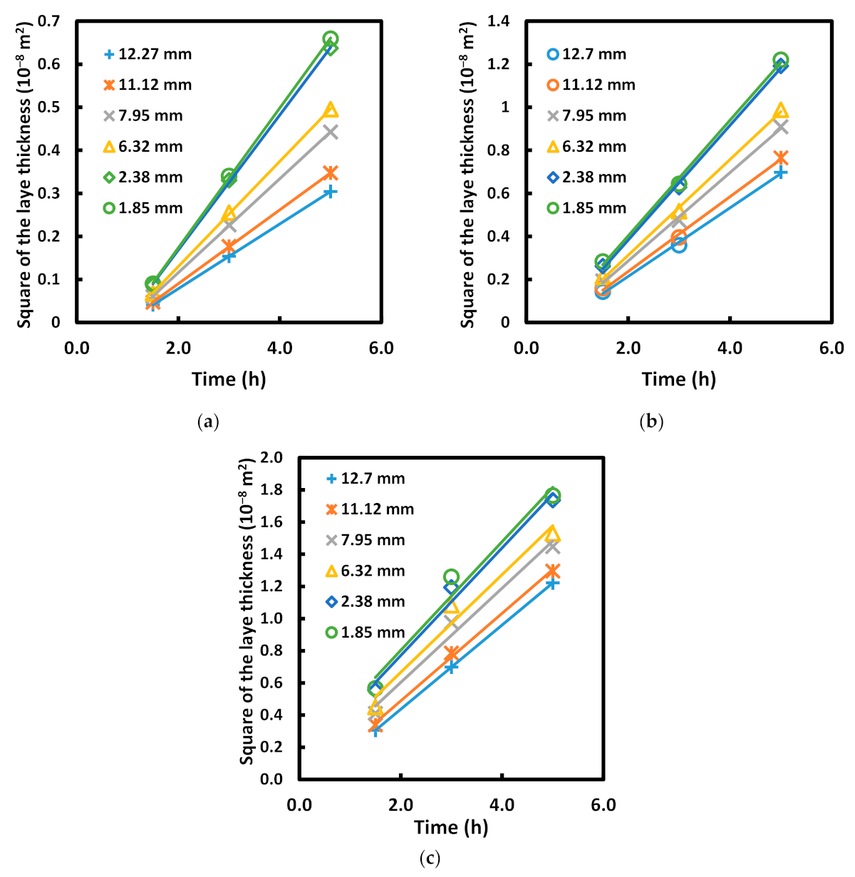
The graphs in Figure 6 show the behavior of the boride layers as a function of the time of treatment. Each sample size was graphed in order to determine the values for the constants of parabolic growth (Ki) individually.
As can be seen in Figure 6, the layer thickness increased not only as a function of the treatment conditions but also as the diameter of the samples decreases. According to the data shown in Table 2, Table 3 and Table 4, it is valid to assume that the layer thickness generated during a boriding process depends not only on the temperature and time but also on the sample size exposed to the process. The rate of layer growth is affected by the size of the samples, and the layer thickness is inversely proportional to the amount of matter involved in the boriding process, even when the temperature and the treatment time remain constant.
Values of Ki for the different process conditions are depicted in Table 5.
The values of Ki for each sample size show a trend to increase not only as a function of the experimental parameters (time and temperature) but also as a function of the amount of matter involved during the process. The increase in Ki indicates that, as the size of the samples increased, the rate of the layer’s growth decreased, so the layer thickness tended to be lower for a given treatment time and temperature.

3.4. Activation Energy and Invested Energy Calculation

Figure 7 shows a plot of ln Ki versus 1/T for the estimation of the activation energy (Qi) as a function of the sample size. The Qi values are also depicted in Table 5.
According to the graph shown in Figure 7, the activation energy required was different for each sample size. This appears to indicate that the activation energy changes as a function of the amount of matter involved during the process, even if the treated material and the treatment conditions stay constant. Nevertheless, as mentioned before, the activation energy represents the energy necessary for boron to move on the substrate, and it is an intrinsic property for each material [9,10], so it should be constant, independent of the sample size. As was suggested in this study, the estimated individual activation energy (Qi) values can be used to estimate real activation energy (Q) values based on knowledge of the number of moles of matter involved in the process.
The invested energy (Ei), sample volume (Vi), and (Ni) values for each sample size are depicted in Table 6.
The values of Ei shown in Table 6 indicate that the energy invested for boron diffusion during a boriding process is directly proportional to the sample size. This behavior is reasonable because the values of Ei are directly dependent on the amount of matter involved during the process (Equation (5)), so as the size of the treated sample increases, the amount of energy invested will also increase. Figure 8 shows the plot of Ei versus Vi according to Equation (8).
The fit of the straight line shows a good correlation for the values of Ei and Vi, which indicates that the slope of the curve can be used to determine the real value of the activation energy for AISI 1018 steel when it is exposed to the boriding process by means of Equation (8). The estimated activation energy (Q) value was 148.30 KJ/mol, which is concordant with values exhibited in the literature.
Table 7 shows the activation energy values obtained by different researchers in previous works.
According to the results presented in this work, the activation energy (Q) seems to depend on the size of the sample involved during the boriding process, since one value of Q (Qi) was achieved for each sample size exposed to boriding. However, it is clear that the activation energy should not change because it is an intrinsic property of the materials; therefore, this paper attempted to establish a real value for the activation energy required for the boriding process for AISI 1018 steel, independent of the amount of matter involved.
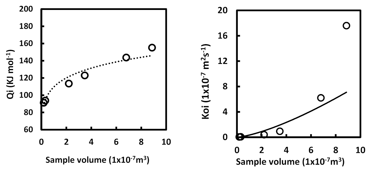
The values of Qi and K0i were graphed as a function of the volume of the samples, as shown in Figure 9.
Using the curves shown in Figure 9, it was possible to establish an Arrhenius model to describe the behavior of the layer thickness as a function of the volume of the treated samples, as follows:
X v o l u m e n = ( 1.814 V 1.1389 ) E X P ( 9.112 x 10 5 V 0.1314 ) ( 8.3144 ) T ( t t 0 )
Equation (11) represents the value of the layer thickness not only as a function of the experimental parameters (time and temperature) but also as a function of the amount of matter involved in the process (volume). It is clear that both the activation energy (Q) and the pre-exponential constant (K0) are influenced by the sample size, so the layer thickness will also be affected by it. On the other hand, (t0) is considered to be the incubation time and represents the amount of time necessary to initiate the layer’s growth. It can be determined using the equation of the straight lines on the graph showing the layer thickness vs. treatment time (Figure 6) prior to the layer’s growth [6].
An explanation for the apparent variation in activation energy values can be provided by “Fourier’s Law of Heat Conduction”, which states that heat conduction occurs when there is a difference in temperature between two parts of a conductor. Thus, for a determined material volume with a given thickness (∆x) and cross section A, opposite phases are at different temperatures (T1) and (T2), and the transferred heat (∆q) flows from the hot side to the cold. The transferred heat in a period of time (∆t) is represented as follows:
H = Δ q d t = k A d T d x
where (H) is the heat transfer rate for a period of time (Watts), (∆q) is the transferred heat (J), (dT) is the variation in temperature for a period of time (K), k is the thermal conductivity of the material (Wm–1·K–1), A is the cross-sectional area through which the heat is flowing (m2), and dx is the size of the conductor medium and represents the radius of the samples (m).
On the other hand, in this study, the treated material, time, and temperature remained constant for any size of sample, but even so, a variation in the layer thickness was observed. Thus, Equation (12) can be rewritten as follows:
H = D A d x
where D is a constant involving all of the parameters mentioned relating to the process of heat transfer. It is clear from Equation (13) that for a boriding process where the treatment conditions and the treated material remain constant, the variation in the heat transfer rate (H) depends mainly on the size of the conductor medium, which represents the size of the samples involved in the process, so variation in the layer thickness is expected to occur when the size of the sample varies.

3.5. Regression Analysis

The numerical results for the regression analysis are shown in Table 8.
Using the values presented in Table 8 and substituting in Equation (10), the proposed empirical model describes the evolution of the layer thickness as a function of the experimental conditions (temperature and time) and the sample size (see Equation (14)):
x = ( 0.07 T 1.16 216.71 )   t ( 0.67 0.77 N 0.64 )
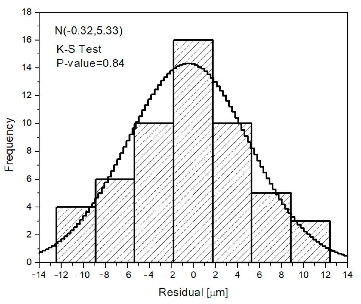
The statistical error or residual (the difference between observed values and estimated) can be fitted to a normal distribution with a low probability of being rejected (p-value = 0.84) and a mean close to zero (µ = –0.32 micrometers). This plot is depicted in Figure 10, where it is possible to observe the residual histogram and its corresponding fitting to a normal distribution.
Under average conditions (temperature and number of moles), the proposed empirical model became:
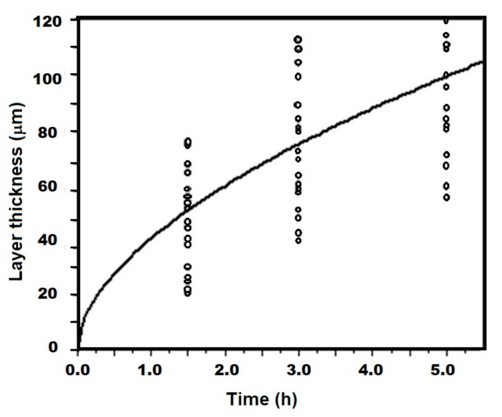
x = 50.29 t 0.56
For the sake of illustration, Equation (15) is plotted with the experimental layer growth results in Figure 11 to observe its evolution over time.
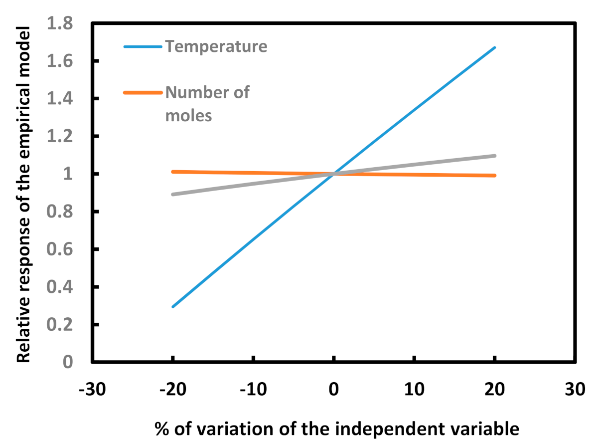
Usually, empirical models are used to determine which variable exerts the greatest influence on a phenomenon [16,24]. In our case, temperature was found to have the greatest influence on layer growth followed by the exposure time and number of moles involved, in that order. Figure 12 shows this result.
After the sensitivity analysis, it is easy to affirm that if one wishes to speed up layer growth, it is necessary to increase the temperature. Even though the number of moles does not have a big influence on the layer growth, it could be an important issue for industrial applications. For example, an industrial application of the boriding process is mesh manufacturing. Estimating the optimal temperature and exposure time during the manufacture of a piece of a specific size could help to save energy and, consequently, money.

4. Conclusions

Based on the results achieved in this study, the following conclusions were established:
  • The layers obtained from the application of the boriding process to AISI 1018 were extremely jagged because of the low content of carbon and alloyed elements.
  • The values of the parabolic growth constant increased not only as a function of the temperature but also as a function of the sample size (Table 5), which indicates that the rate of layer growth is highly dependent on the experimental parameters and the size of the sample involved in the process.
  • The estimated activation energy was 148.3 KJ mol–1, which seems low compared with values reported in the literature; however, this indicates that as the size of the sample decreases, the amount of energy required to make the process occur is also lower.
  • According to the exhibited results, the size of the samples involved during a boriding process has to be considered to obtain better layer thickness results.
  • Using regression analysis, it is possible to construct an empirical model that estimates layer growth in a boriding process by taking the three main independent variables—temperature, exposure time, and the amount of substance—into consideration. After this study, we can confirm that temperature is the variable that exerts the greatest influence on layer growth, followed by exposure time and number of moles, in that order.
  • Finally, although many authors have reported that the layer thickness is independent of the sample shape and only depends on features such as the treatment conditions, the chemical composition of the substrate and the boron potential supplied during the boriding process, according to the results achieved in the present study the kinetic of growth and, by consequence, the layer thickness also depend on the number of moles of substance exposed to boriding, represented by the volume of the sample.

Author Contributions

Conceptualization: P.A.R.-T., E.H.-S.; methodology: E.H.-S. and J.C.V.; investigation, P.A.R.-T., J.A.Y.-H. and N.E.G.-A., resources, P.A.R.-T., experimental work: C.O.-Á. and R.C.-E., writing E.H.-S. and J.C.V., review and editing: N.E.G.-A. and J.C.V. All authors gave final approval and agree to be accountable for all aspects of the work. All authors have read and agreed to the published version of the manuscript.

Funding

This work was supported by research grant 20195411 and grant 20200748 from the Instituto Politécnico Nacional in Mexico.

Institutional Review Board Statement

Not applicable.

Informed Consent Statement

Not applicable.

Data Availability Statement

No new data were created or analyzed in this study. Data sharing is not applicable to this article.

Acknowledgments

The authors wish to thank the Center of Nanosciences and Micro-Nano Technologies of the Instituto Politécnico Nacional for their cooperation. The comments provided by the reviewers are greatly appreciated.

Conflicts of Interest

The authors declare no conflict of interest. The funders had no role in the design of the study; in the collection, analyses, or interpretation of data; in the writing of the manuscript; or in the decision to publish the results.

References

  1. Allaoui, O.; Bouaouadja, N.; Saindernan, G. Characterization of boronized layers on a XC38 steel. Surf. Coat. Tech. 2006, 201, 3475–3482. [Google Scholar] [CrossRef]
  2. Keddam, M.; Chentouf, S.M. A diffusion model for describing the bilayer growth (FeB/Fe2B) during the iron pow-der-pack boriding. Appl. Surf. Sci. 2005, 252, 393–399. [Google Scholar] [CrossRef]
  3. Hernández-Sánchez, E.; Domínguez-Galicia, Y.M.; Orozco-Álvarez, C.; Carrera-Espinoza, R.; Herrera-Hernández, H.; Ve-lázquez, J.C. A Study on the Effect of the Boron Potential on the Mechanical Properties of the Borided Layers Obtained by Boron Diffusion at the Surface of AISI 316L Steel. Adv. Mater. Sci. Eng. 2014, 2014. [Google Scholar] [CrossRef] [Green Version]
  4. Hernández-Sanchez, E.; Velázquez, J.C. Kinetcis of growth of iron boride layers on a low-carbon steel surface. In Laborato-ry Unit Operations and Experimental Methods in Chemical Engineering, 1st ed.; Basha, O.M., Morsi, B.I., Eds.; InTechOpen: London, UK, 2018; pp. 37–55. [Google Scholar]
  5. Bodycote. The Leading Provider of Heat Treatment and Specialist Thermal Processing Services Worldwide. Available online: http://hef.mx/wp-content/uploads/2017/06/Catalogo-de-sales-HEF-Durferrit.pdf (accessed on 1 November 2020).
  6. Keddam, M.; Ortiz-Domíguez, M.; Campos-Silva, I.; Martínez-Trinidad, J. A simple model for the growth kinetics of Fe2B iron boride on pure iron substrate. Appl. Surf. Sci. 2010, 256, 3128–3132. [Google Scholar] [CrossRef]
  7. Matuschka, A.; Von Graf, A. Boronizing, 1st ed.; Hanser Publisher: Wemding, Germany, 1980; pp. 31–60. [Google Scholar]
  8. Jain, V.; Sundararajan, G. Influence of the pack thickness of the boronizing mixture on the boriding of steel. Surf. Coat. Tech. 2002, 149, 21–26. [Google Scholar] [CrossRef]
  9. Campos, I.; Bautista, O.; Ramírez, G.; Islas, M.; De La Parra, J.; Zuñiga, L. Effect of boron paste thickness on the growth kinetics of Fe2B boride layers during the boriding process. Appl. Surf. Sci. 2005, 243, 429–436. [Google Scholar] [CrossRef]
  10. Trautmann, F. Borideing with Duferrit DURBORIT. Technical Information. H.E.F. Group. Available online: http://hef.mx/wp-content/uploads/2017/06/Catalogo-de-sales-HEF-Durferrit.pdf (accessed on 1 November 2020).
  11. Genel, K.; Ozbek, I.; Bindal, C. Kinetics of boriding of AISI W1 steel. Matls. Sci. Eng. A. 2003, 347, 311–314. [Google Scholar] [CrossRef]
  12. Sen, S.; Sen, U.; Bindal, C. The growth kinetics of borides formed on boronized AISI 4140 steel. Vacuum 2005, 77, 195–202. [Google Scholar] [CrossRef]
  13. Sen, S.; Sen, U.; Bindal, C. An approach of kinetic study of borided steels. Surf. Coat. Technol. 2005, 191, 274–285. [Google Scholar] [CrossRef]
  14. Ozbek, I.; Bindal, C. Kinetics of borided AISI M2 high speed Steel. Vacuum 2011, 86, 391–397. [Google Scholar] [CrossRef]
  15. Sen, S.; Ozbek, I.; Sen, U.; Bindal, C. Mechanical Behavior of Borides Formed on Borided Cold Work Tool Steel. Surf. Coat. Technol. 2001, 135, 173–177. [Google Scholar] [CrossRef]
  16. Velázquez, J.C.; Cruz-Ramirez, J.C.; Valor, A.; Venegas, V.; Caleyo, F.; Hallen, J.M. Modeling localized corrosion of pipeline steels in oilfield produced water environments. Eng. Fail. Anal. 2017, 79, 216–231. [Google Scholar] [CrossRef]
  17. Velázquez, J.C.; Valor, A.; Caleyo, F.; Venegas, V.; Espina-Hernandez, J.H.; Hallen, J.M.; Lopez, M.R. Pitting corrosion models improve integrity management, reliability. Oil Gas J. 2009, 107, 52–62. [Google Scholar]
  18. Velázquez, J.C.; Valor, A.; Caleyo, F.; Venegas, V.; Espina-Hernandez, J.H.; Hallen, J.M.; Lopez, M.R. Study helps model buried pipeline pitting corrosion. Oil Gas J. 2009, 107, 64–73. [Google Scholar]
  19. Velázquez, J.C.; Van Der Weide, J.A.M.; Hernández-Sanchez, E.; Herrera-Hernández, H. Statistical modelling of pitting corro-sion: Extrapolation of the maximum pit depth-growth. Int. J. Electrochem. Sci. 2014, 9, 4129–4143. [Google Scholar]
  20. Terán, G.; Capula-Colindres, S.; Angeles-Herrera, D.; Velázquez, J.C.; Fernández-Cueto, M.J. Estimation of fracture toughness K IC from Charpy impact test data in T-welded connections repaired by grinding and wet welding. Eng. Fract. Mech. 2016, 153, 351–359. [Google Scholar] [CrossRef]
  21. Hernández-Sanchez, E.; Rodriguez-Castro, G.; Meneses-Amador, A.; Bravo-Bárcenas, D.; Arzate-Vazquez, I.; Mar-tínez-Gutiérrez, H.; Romero-Romo, M.; Campos-Silva, I. Effect of the anisotropic growth on the fracture toughness meas-urements obtained in the Fe2B layer. Surf. Coat. Tech. 2013, 237, 292–298. [Google Scholar] [CrossRef]
  22. Brakman, C.M.; Gommers, A.W.J.; Mittemeijer, E.J. Boriding of Fe and Fe–C, Fe–Cr, and Fe–Ni alloys; Boride-layer growth kinetics. J. Mater. Res. 1989, 4, 1354–1370. [Google Scholar] [CrossRef]
  23. Dybkov, V.I.; Siderko, R.; Goncharuk, L.V.; Khoruzha, V.G.; Samelyuk, A.V. Microstructure, Growth Kinetics, and Abrasive Wear Resistance of Boride Layers on Fe–30% Cr Alloy. Powder Metall. Met. Ceram. 2013, 51, 518–530. [Google Scholar]
  24. Velázquez, J.C.; Caleyo, F.; Valor, A.; Hallen, J.M. Predictive model for pitting corrosion in buried oil and gas pipelines. Co-rrosion 2009, 65, 332–342. [Google Scholar] [CrossRef]
  25. Energía de Activación Para la Difusión del Boro Durante la Borurización de un Acero de Bajo Carbono. Available online: http://www.reibci.org/publicados/2016/dic/2000116.pdf (accessed on 20 December 2020).
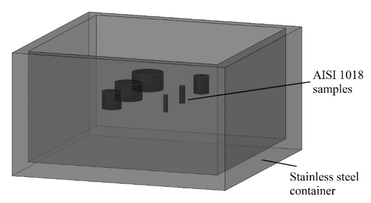
Figure 1. Schematic representation of the collocation of the samples inside the container.
Coatings 11 00259 g001
Figure 2. Methodology used for the layer thickness measurement.
Coatings 11 00259 g002
Figure 3. Cross section of the samples borided at 950 °C for 3 h with diameters of (a) 12.7 mm, (b) 1.85 mm.
Coatings 11 00259 g003
Figure 4. X-ray diffraction (XRD) pattern of the 11.12 mm diameter sample exposed to treatment at 950 °C for 5 h.
Coatings 11 00259 g004
Figure 5. Raman spectra of the borided layer: (a) along the cross section at different distances from the surface and (b) at the surface and substrate.
Coatings 11 00259 g005
Figure 6. Behavior of the layer thickness as a function of the treatment time for treatment temperatures of (a) 900 °C, (b) 950 °C, and (c) 1000 °C.
Coatings 11 00259 g006
Figure 7. Behavior of the activation energy according to the Arrhenius model for the different sample sizes.
Coatings 11 00259 g007
Figure 8. Ei vs. Vi for the calculation of the real activation energy (Q).
Coatings 11 00259 g008
Figure 9. Behavior of Q and K0i as a function of the size of the treated samples.
Coatings 11 00259 g009
Figure 10. Residual histogram for the proposed empirical model.
Coatings 11 00259 g010
Figure 11. Observed layer thickness evolution. The power law function (solid line black curve) represents Equation (15).
Coatings 11 00259 g011
Figure 12. Sensitivity analysis for Equation (14).
Coatings 11 00259 g012
Table 1. Chemical composition of AISI 1018 steel (wt.%).
CMnSiP max.S max.Fe
0.15–0.200.60–0.900.15–0.300.040.05Balance
Table 2. Thicknesses of the boride layers obtained on AISI 1018 steel exposed to treatment at 900 °C for 1.5, 3, or 5 h.
Diameter
(mm)
Treatment Time (h)
1.535
Layer thickness (µm)
12.720.75 ± 5.2539.22 ± 6.0355.16 ± 7.16
11.1221.69 ± 4.2842.02 ± 7.2358.93 ± 9.25
7.9524.6 ± 5.4547.62 ± 7.2766.51 ± 8.36
6.3226.02 ± 4.1250.51 ± 8.1270.39 ± 8.15
2.3829.54 ± 4.1867.48 ± 9.3279.81 ± 9.69
1.8530.02 ± 7.3458.33 ± 7.2781.92 ± 10.54
Table 3. Thicknesses of the boride layers obtained on AISI 1018 steel exposed to treatment at 950 °C for 1.5, 3 or 5 h.
Diameter
(mm)
Treatment Time (h)
1.535
Layer Thickness (µm)
12.737.84 ± 4.2359.92 ± 6.0383.56 ± 8.85
11.1239.88 ± 5.1162.89 ± 7.4387.48 ± 9.17
7.9543.98 ± 5.9468.83 ± 5.9495.35 ± 9.42
6.3246.09 ± 7.6371.88 ± 7.1399.43 ± 7.17
2.3851.18 ± 5.2379.27 ± 8.12109.17 ± 9.34
1.8553.25 ± 7.8280.26 ± 8.37110.48 ± 10.12
Table 4. Thickness of the boride layers obtained on AISI 1018 steel exposed to treatment at 1000 °C for 1.5, 3, or 5 h.
Diameter
(mm)
Treatment Time (h)
1.535
Layer Thickness (µm)
12.755.27 ± 5.3083.56 ± 9.59110.54 ± 11.89
11.1258.19 ± 4.2588.63 ± 6.67113.79 ± 10.01
7.9564.07 ± 4.5498.81 ± 8.89120.31 ± 12.67
6.3267.09 ± 6.83104.03 ± 8.11123.66 ± 11.63
2.3874.38 ± 6.28109.25 ± 6.66131.67 ± 14.58
1.8575.25 ± 6.82112.25 ± 8.42132.86 ± 11.48
Table 5. Values of Ki as a function of the different conditions of treatment. Ki values were independently evaluated for each sample size.
Diameter
(mm)
Ki (m2·s−1)Qi
(KJ mol−1)
900 °C950 °C1000 °C
12.72.09 × 10−134.42 × 10−137.27 × 10−13155.22
11.122.38 × 10−134.83 × 10−137.56 × 10−13143.76
7.953.03 × 10−135.70 × 10−138.14 × 10−13123.04
6.323.39 × 10−136.18 × 10−138.44 × 10−13113.55
2.384.36 × 10−137.40 × 10−139.2 × 10−1393.8
1.854.5 × 10−137.47 × 10−139.4 × 10−1391.20
Table 6. Values of invested energy (Ei) as a function of the sample size exposed to the boriding process.
Di
(m)
Vimi
(kg)
Ni
(Moles)
Ei
(J)
(m3)
0.01278.86 × 10−76.92 × 10−31.24 × 10−119225.689
0.011126.79 × 10−75.30 × 10−39.50 × 10−213650.855
0.007953.47 × 10−72.71 × 10−34.85 × 10−25971.280
0.006322.19 × 10−71.71 × 10−33.07 × 10−23482.729
0.002383.11 × 10−82.43 × 10−44.35 × 10−3408.009
0.001851.88 × 10−81.47 × 10−42.63 × 10−3238.133
Table 7. Activation energies achieved by different researchers.
MaterialMethodLayer MorphologyActivation Energy
(KJ·mol–1)
Reference
AISI W1Solid mediaFlat front171.2[11]
AISI 4140Molten saltSaw-toothed218.4[12]
AISI D2Molten saltSaw-toothed170.0[13]
AISI 1018B4C pasteSaw-toothed161.8[15]
AISI 1005Solid mediaSaw-toothed133.8[25]
Armco ironGaseousSaw-toothed120.6[25]
AISI 1018Solid mediaSaw-toothed148.3present
Table 8. Results of the regression analysis (numerical values).
Coefficient
R2 k 0 k 1 η 0 η 1 α β
0.970.07–216.710.67–0.771.160.64
Publisher’s Note: MDPI stays neutral with regard to jurisdictional claims in published maps and institutional affiliations.