Article

A Multi-Analytical Non-Invasive Approach to Aqueous Cleaning Systems in Treatments on Bowed String Musical Instruments

1
Department of Physics, Università degli Studi di Milano, via Celoria 16, 20133 Milano, Italy
2
Violin Making School of Milan, via Noto 4, 20141 Milan, Italy
3
Arvedi Laboratory of Non-Invasive Diagnostics, CISRiC, University of Pavia, via bell’Aspa 3, 26100 Cremona, Italy
4
Department of Mathematical, Physical and Computer Sciences, University of Parma, Parco Area delle Scienze 7/A, 43124 Parma, Italy
5
Department of Musicology and Cultural Heritage, University of Pavia, Corso Garibaldi 178, 26100 Cremona, Italy
*
Author to whom correspondence should be addressed.
Coatings 2021, 11(2), 150; https://doi.org/10.3390/coatings11020150
Submission received: 28 December 2020 / Revised: 21 January 2021 / Accepted: 27 January 2021 / Published: 29 January 2021
(This article belongs to the Special Issue Surface and Interface Analysis of Cultural Heritage)

Abstract

:
Restoration and conservation procedures for historical musical instruments involve several issues, also connected with their frequent being played. One of the most delicate procedures for their preservation is the cleaning of surfaces from soil and dirt which have accumulated over the years. In fact, when external particles reach the surface, a fraction of them can deposit on it. Moreover, the contact with the player can generate chemical-physical changes, rapidly warming and wetting the surfaces through sweat deposition. This work focused on the cleaning methods of surfaces of bowed string musical instruments by a systematic and analytical approach. The selective cleaning procedure of varnished surfaces from grime and soil needs to be performed without compromising the original matter. Therefore, a dirty surface was reproduced on a set of varnished mock-ups and different water-based cleaning systems—generally used by restorers—were tested. The procedures were monitored in each step with several analytical methods: multispectral imaging (near-infrared (NIR), IRFC, visible imaging (VIS), UV-induced visible fluorescence), stereomicroscopy, XRF and FTIR spectroscopies allowed us to non-invasively outline the cleaning system efficacy. The results highlighted different levels of cleaning and, in some cases, it was possible to identify the best selectivity for the different procedures.

1. Introduction

One of the most usual—as well as delicate—procedures for the preservation of ancient musical instruments is the cleaning of surfaces from layers of deposited soiling. According to conservation requirements, pollution and other atmospheric chemical compounds should never deposit on historical artifacts [1,2]. When it occurs, their removal is highly recommended, in order to help re-establish the original surface status and to minimize the risk of the soiling embedding within the varnish layer. Dirt accumulation on the musical instrument depends on different factors, such as the climatic conditions, the presence of pollutants in the environment where the instrument is conserved or played, the dirt particle size, or the varnish surface roughness and its state of conservation [3]. This phenomenon is also related to the fact that many historical instruments, from private and public collections, are still played by musicians nowadays. The contact with the player may prompt dirt deposition and adhesion on the surface, since the instrument is exposed to warm and wet conditions during hours-long practice and performance [4].
In this work, we proposed an innovative and standardized methodology to monitor the soiling removal from bowed musical instrument surfaces, using a novel approach to different cleaning treatments that consider the specific conservation conditions of the objects. This was possible only by developing a scientific method able to characterize both the dirt composition and the layered surface, so as to allow the assessment of the cleaning effectiveness. Likewise, the purpose of the treatment is to evenly remove the layer of deposited soiling while respecting the original matter and minimizing any risks associated with the use of cleaning systems on the surface [5].
Only a few studies were conducted to achieve an overview about the compositional nature of the soil on artifacts, by sampling and analyzing it. Most of the existing literature is devoted to cleaning procedures for paintings and refers to the method proposed by Wolbers in 1992 [6], who improved the one proposed by Florio-Mersereau [7] based on studies of real soil samples collected in US cities. Wolbers’ improvements were done with the idea of better representing indoor soiling, as that one present in a museum environment. In the recipe described in his work, inorganic materials like cement, silica, kaolin, iron oxides, carbon black and mineral oil, and organic ones like peat moss, starch, and gelatin, are listed.
For the experimental part of our work, four mock-ups were realized to simulate a characteristic bowed musical stratigraphy. A soiling mixture was prepared and then applied following the method proposed by Wolbers. Subsequent cleaning tests were performed following—as well as reviewing—the methodologies commonly used in other art conservation fields, in particular that of easel paintings [8,9,10]. The aim of the work was testing some already-known cleaning methods on bowed string musical instrument surface and developing an analytical method to monitor the cleaning results.
Water-based cleaning systems, which use surfactants to improve the capability of water to interact with dirt, were tested. Surfactants have a quite wide range of action. Firstly, they lower the surface tension thus enhancing the wetting power of water. In the following aggregation of surfactant molecules, the forming micelles are able to embed dirt or other materials as well as having an emulsifying power [11,12]. Over the last decades, the application of aqueous solutions has gained increasing attention for a twofold aspect: on one hand, the health considerations and risks for operators and, on the other, the possibility of controlling both the cleaning efficiency and the interaction with the media [13]. In addition, they maintain ease of use and cheapness. These systems can be used by means of a carrier medium, or a thickener, or a gelling agent to localize and control their action. For the reasons above described, four water-based cleaning solutions were selected in this work, considering the possibility to test some already well-known products in violin restoration and also new ones.
After each stage of the mock-up preparation (i.e., mock-ups varnishing, soiling, and cleaning), non-invasive analyses were performed in order to gain information on the evolution of the process and then on the efficacy of the cleaning procedures. Instrumental parameters were tuned to search all the factors that indicate the presence of dirt, providing criteria to describe the soiling removal efficacy of tested cleaning systems. A preliminary stereomicroscopy investigation was followed by imaging acquisition in the visible range in order to evaluate color changes. Therefore, multispectral imaging assessed the ultraviolet-induced visible fluorescence (UVIFL) phenomena and the estimated infrared response of the dirty layer near infrared (NIR) imaging (850–1000 nm) and infrared false color (IRFC). Energy-dispersive X-ray fluorescence (portable EDXRF) and reflection Fourier Transform Infrared (FTIR) spectroscopies allowed us to acquire punctual and map information about surface composition and dirt compound distribution before and after the cleaning procedures. The choice of using portable and non-invasive techniques was motivated by the intention of applying them on real artifacts, both in museums and in restoration workshops, without the need for sampling. In particular, the choice was for a set of analyses that have been extensively used in material analysis of historical musical instruments [14]. In this way, the cleaning was monitored in each step in a safe and feasible way.

2. Materials and Methods

2.1. Mock-Ups

The creation of the mock-ups followed a common approach for the reproduction of musical instruments surface [15,16]. A plywood plane (15 mm thick) was veneered with a maple panel, the surface finished with wood scrapers, and then sized with casein glue (Bresciani s.r.l., Milan, Italy). The casein glue was obtained by solubilizing casein powder in a KOH 4% w/w water solution (ratio 1:5 w/w). Five coats of varnish were subsequently applied using a flat synthetic brush. The oil-based varnish is composed of linseed oil (cat. no. 73,054 Kremer Pigmente, Aichstetten, Germany) and colophony (cat. no. 60,305 Kremer Pigmente, Aichstetten, Germany), in an oil:resin ratio of 2:1 [17]. After varnishing, the surface was polished with mineral oil (Le Grand Chic, Latina, Italy) and diatomaceous earth (cat. no. 599,920 Kremer Pigmente, Aichstetten, Germany) by swab, then removed with a towel. Residues of mineral oil were absorbed by applying a small quantity of white flour and removing it after a few seconds by soft brush [18]. Four panels sized 8 cm × 15 cm and a reference sample were prepared.
In the subsequent step, the sized and varnished mock-ups were covered by a soiling mixture, prepared following the Wolbers’ recipe reported in [6] and largely used in the last decades as a standard in the cleaning tests for easel paintings. The recipe is based on a mixture of different organic and mineral dry compounds, which are blended together to obtain a finely divided black/grey powder (particle size is between units and hundreds of μm). The inorganic fraction is composed of cement, silica, kaolin and iron oxides (umber); the organic one includes peat moss, starch, gelatin, and carbon black. A dispersion of the dry soiling mixture in a solution 4.5% v/v of mineral oil in chloroform was applied on the varnished surface by means of an airbrush from a distance of about 20 cm, at full pressure. The procedure is displayed in Figure 1a.

2.2. Cleaning Systems

The tested cleaning systems are listed in Table 1. They are all water-based methods applied by means of different delivery systems. Korean paper and Agarose rigid gel [19,20] (Figure 1c,d respectively) were used for this purpose, except in the case of the w/o emulsion (Figure 1b) that can be applied as it is. Also, the synthetic saliva is tested as an aqueous solution, even if it is based primarily on chelating action of citrates [11] rather than on surfactants as the other used methods.
For each medium, four different application times were chosen:
  • Korean paper: 2, 5, 10, and 20 min, respectively called K1, K2, K3, and K4;
  • agarose gel: 10, 20, 30 min and 5 h, respectively called A1, A2, A3, and A4;
  • w/o emulsion: 1, 2, 5, 10 min, respectively called E1, E2, E3, and E4.

2.3. Non-Invasive Techniques

Each analysis was performed on the varnished mock-up surface before the soiling, after the soiling, and after the cleaning procedures.
Details of the soiled and cleaning surfaces were observed using an Olympus stereomicroscope (Olympus, Tokyo, Japan) (4–50× magnification) in visible light, equipped with Olympus HD DP73 camera and the Stream Essentials software 2.1 (Olympus, Tokyo, Japan) Each mock-up was observed both in direct and in grazing light, in order to better represent the three-dimensionality of the dirt layer.
Multispectral imaging techniques were used on dirty and cleaned mock-ups to evaluate the action of the different cleaning systems under ultraviolet, visible, and infrared light sources. Images were acquired using a modified Nikon D810 digital camera, Nikon, Tokyo, Japan) able to detect radiation from 350 to 1000 nm, equipped with a 50 mm lens (AF-S NIKKOR 1:1.8G, Nikon, Tokyo, Japan). Two halogen lamps placed symmetrically at 45° with respect to the mock-up surface were used as light sources for both infrared and visible imaging, using respectively a B + W 093, an 850 nm long-pass filter for the infrared and a Hoya UV/IR cut filter (Kenko Tokina Co., Ltd., Tokyo, Japan) together with a Coma BG40 filter (Schott Optics, Mainz, Germany) for the visible acquisition. Two Philips TL-D 36 W BBL IPP low-pressure Hg Wood tubes (Philips, Amsterdam, Netherlands) (emission peak at 365 nm) were used for UVIFL, adding to the Hoya UV/IR cut filter the Coma KV 418 long-pass filter (cut off of wavelengths lower than 418 nm). Each image was acquired setting the aperture at f11 and ISO 100, with different exposure time. Infrared false-color images were obtained using the red and green channel of the RGB visible image and the infrared image.
EDXRF and FTIR reflection spectroscopies were used to collect information about the elemental and molecular content of dirt, respectively. X-ray fluorescence spectra were acquired by using the portable energy dispersive XRF spectrometer ELIO (Bruker Corporation Billerica, MA, USA). The excitation source works with an Rh anode and the beam is collimated to a spot diameter on the sample surface of about 1.3 mm. XRF measurements were carried out by fixing the tube voltage at 40 kV and the tube current at 40 μA, for a measured time of 480 s (8 min) and setting acquisition channels at 2048; the data were collected using ELIO 1.5.5 software (Bruker Corporation, Billerica, MA, USA). In order to give rough estimates of elemental abundances, the spectra were normalized to the net area counts of the Rhodium Kα between 20 and 22.5 keV, and the values of the area under the curve of the most intense peaks of each spectrum were considered. For the mapping mode, the same parameters of voltage and current were kept, while the measured time was set at 2 s per point. The step between two points was set at 1500 μm. Infrared reflection spectra were collected using the Alpha portable spectrometer (Bruker Corporation, Billerica, MA, USA) equipped with the R-Alpha module. Spectra were collected between 7500 and 375 cm−1 at the resolution of 4 cm−1. The acquisition time was 1 min, extended to 2 or 3 min when the intensity of the reflected radiation was lower. The background was acquired using a gold mirror. The investigated area, as determined by the beam diameter, is approximately 20 mm2. Data were processed using OPUS 7.2 software (Bruker Corporation, Billerica, MA, USA). The spectrum intensity unit was defined as pseudo-absorbance [log(1/R); R = Reflectance]. For the study of most of the organic bands, reflection infrared spectra were transformed into absorbance spectra by applying the Kramers-Kronig (KK) algorithm (included in the OPUS 7.2 software package).
The NicoletTM iNTM10 Infrared Microscope spectrometer (Thermo Fisher Scientific, Waltham, MA, USA) was used in transmission mode. The chemical composition of pure components of the soiling mixture was analyzed by means of KBr pellets (standard pressure), in cold and room temperature modalities. Data were processed using EZ OMNICTM Specta software (ver. 7.3, Thermo Fisher Scientific, Waltham, MA, USA).

Further Considerations on Imaging Analysis

Raw images were processed with Adobe Camera Raw (Adobe, San Jose, CA, USA) for proper color management using a colorimetric reference target (X-Rite ColorChecker Passport 24 patches) and saved in tiff format in sRGB color space. In addition, tiff color images were compared for reference regions of interest (ROIs) to standard colorimetric data acquired with the CR-400 colorimeter (Konica Minolta, Tokyo, Japan). Comparison showed an average colorimetric difference below ΔE = 1.5 CIEDE units, allowing us to use—in this particular case—visible images of mock-ups for extracting colorimetric data during the treatments. This procedure was followed in order to quantitatively assess the efficacy of the cleaning systems in terms of the ability in restoring the original color in ROIs corresponding to areas that are statistically meaningful (about 2 cm2 = 150,000 square pixel) and to perform the measurements even after the end of the whole cleaning procedures.
For quantitative comparisons, colorimetric data were then extracted from visible images using the ImageJ software (ver. 1.8.0. NIH, Bethesda, MD, USA) [22] in the CIELab 1976 color space [23,24]. Thirty-three ROIs were selected on the mock-ups, placed in correspondence of each spot that was chosen to be treated. For each ROI, colorimetric data were extracted before and after the cleaning treatment. The software computed the average L*, a*, b* coordinates, and their standard deviations of the mean (SDOM), in order to compare the two data sets. The choice to compare confined ROI values of dirt color instead of global mean values was led by the fact that dirt distribution in the mock-ups, as well as in real artifacts, is pretty not homogeneous, and mean values would have been of little significance. Limiting the spatial colorimetric information to a ROI with lower intrinsic variability (std. dev. about 2% in a single ROI), will lead to more reliable comparisons.
Color comparison in all the steps, from the soiling to the cleaning, was essential because it enabled us to correctly correlate the color changes with the cleaning action on the mock-up surface, rather than to the specific color management or acquisition processes.
In the cases of UVIFL and NIR imaging, since colorimetry is not defined in these bands, pixel values were extracted instead of the colorimetric data from the images. For this purpose, the comparison is limited to the ROIs inside a single image.

3. Results and Discussion

3.1. Stereomicroscopy

In direct visible light, the distribution of aggregates of white inorganic compounds and black carbon was clearly observed (Figure 2a). Furthermore, some red grains of iron oxide were detected. The roughness of the soiled surfaces is also displayed by grazing light observations (Figure 2b). Macro photography (Figure 2c) evidently shows that the soiled surfaces are grained and irregular in both the cleaned and dirty areas, even though some differences can be perceived. The main distinction between the areas is represented by the color: the cleaning, in fact, seemed to result much more effective in removing the dark-colored compounds (i.e., black carbon and cement) than the inorganic white powders (i.e., kaolin and lime), these latter being responsible for the grainy surface appearance.

3.2. Multispectral Imaging

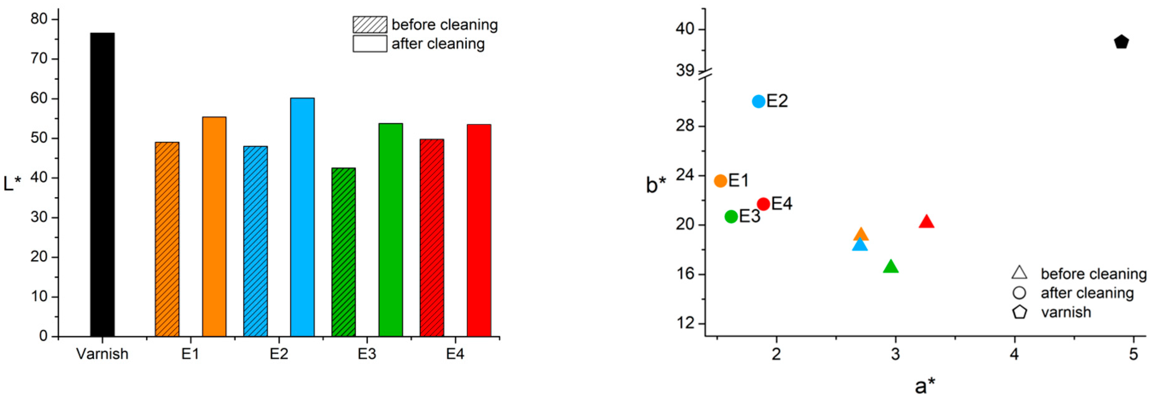
Multispectral images and graphic representations of colorimetric data extracted from VIS image of mock-up II—as the most representative—are displayed respectively in Figure 3 and Figure 4. Images and graphs of mock-ups I, III and IV are available as Supplementary Materials (Figures S1–S7).
To evaluate the visible dirt removal action for each treatment, both the color difference (ΔE*ab) [25] and the total color difference CIEDE2000 (ΔE00) [26] were calculated. Therefore, ΔE00 was used to estimate the efficacy of each cleaning process: the ΔE00 results were divided into three groups as low (from 1 to 5 CIEDE units), intermediate (from 5 to 9 CIEDE units), and high cleaning performance (from 9 to 13 CIEDE units). If ΔE00 relative to the same ROI of the mock-ups—before and after the treatment—were smaller or equal to the distinguishability threshold (i.e., 1 CIEDE unit) [24], then the cleaning was considered unsuccessful. Lightness, chroma, and hue differences (respectively ΔL00, ΔC00 and ΔH00) were calculated alongside with ΔE00 in order to have detailed information about components of dirt which have been removed (colored components or transparent ones). In general, lightness was the color coordinate that was most restored by the treatments, whereas the hue was the least affected. The results are reported in Table S1.
For what concerns visible UV-induced fluorescence images, the dirt layer is completely black under UV light and, as expected, the varnish color fluorescence starts reappearing after successful treatments. It is interesting to note that this behavior is better appreciable with this technique rather than in visible images. In particular, changes in fluorescence color with respect to the varnish reference area, is an indication that one or various compounds had deposited on the surface. This is the case for synthetic saliva in agarose gel pads (mock-up I, A2 and A3): an orange shade in fluorescence is observed, slightly different from the yellowish fluorescence of the rest of the varnish. On contrary, the mock-up II is a clear exemplum of how we expected to behave the cleaning: the color fluorescence of the cleaned areas matches one of the reference varnish areas, even if cleaning did not perform a complete removal action and therefore a gray shade due to not-cleaned dirt layer is still present.
As regarding NIR imaging, we can evaluate the cleaning action especially on NIR opaque materials, such as carbon black [27,28]: comparisons between the UVIFL and NIR imaging allowed us to understand on which components the cleaning has had more efficiency. Observations assessed in particular that NIR opaque materials were removed best on mock-up II and III.

3.3. XRF Spectroscopy

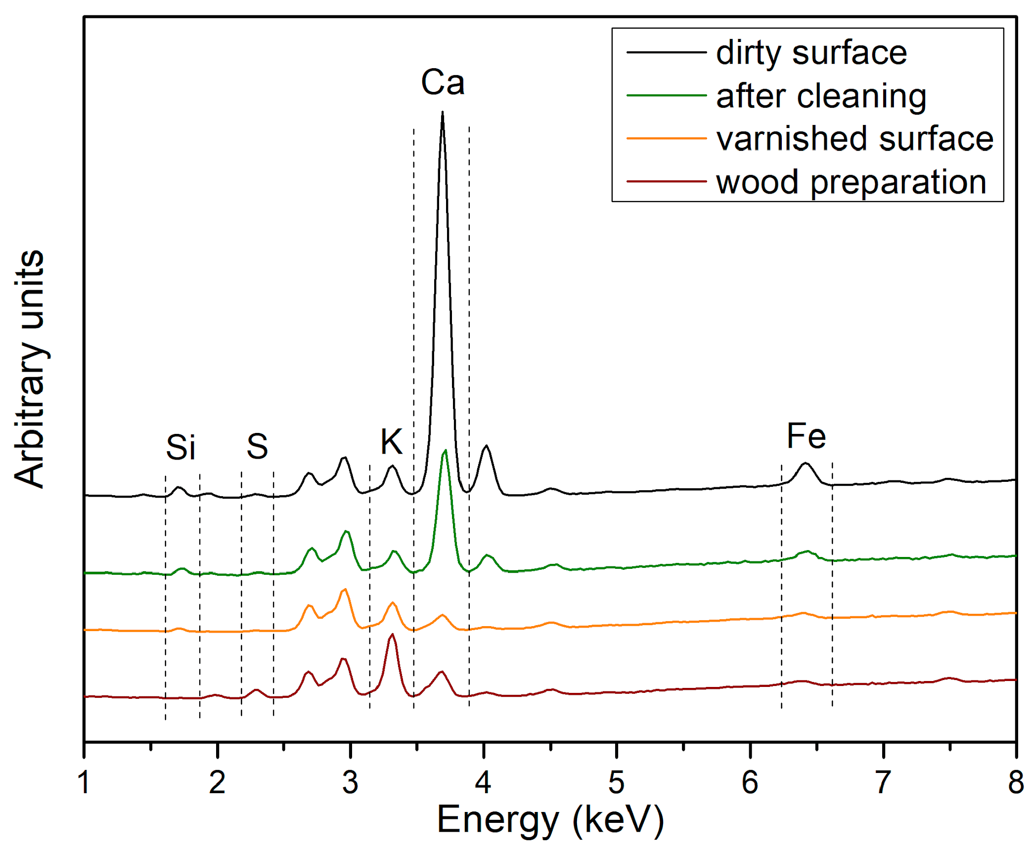
XRF spectra collected in correspondence of the dirty areas (Figure 5) show the same elemental distribution of the pure soiling mixture (Figure S1, see Supplementary Materials for more information). Detected elements on dirty surfaces are Ca, Fe, K, Si, and S, listed from the highest to the lowest values according to the mean value of counts per area. We can relate each detected element to specific substances of the soiling mixture: Ca (kaolin, cement), Fe (umber, cement), K (peat moss, kaolin), Si (kaolin, silica, cement), S (most of the dirt components). The elemental distribution of the varnished mock-ups before the soiling procedure was taken as a reference. After the cleaning procedure, XRF emissions associated with the presence of dirt got typically lower and the spectra became similar to those collected on varnish before soiling. In the case of an increase in area counts for a specific element in the comparison, it was supposed that some residue left on the surface by the treatment. For a deeper insight on EDXRF data analysis methods, see chapter S3.1.
According to K, Ca and Fe counts, three subsequent degrees of cleaning efficacy were defined: low cleaning performance if the cleaned area counts differed more than 1 standard deviation (SD) from the dirt surface counts mean value; intermediate performance if the difference was between 1 and 1.5 SD; good performance if it exceeded 2 SD. Due to the underestimation of Si and S, it is not possible to establish a cleaning performance scale for these light elements and we could only say if there is a change before and after the treatments, therefore results were divided into successful and null ones. No variations in net area counts after the cleaning treatment meant that the method was unsuccessful. Calcium was the most affected element by cleaning treatments, also according to its major detected abundance. Emulsion was the most successful in the removal action, in particular with Ca and Fe compounds. Silica counts lowered with almost each treatment, whereas S and K removal was diversified according to the used cleaning process.
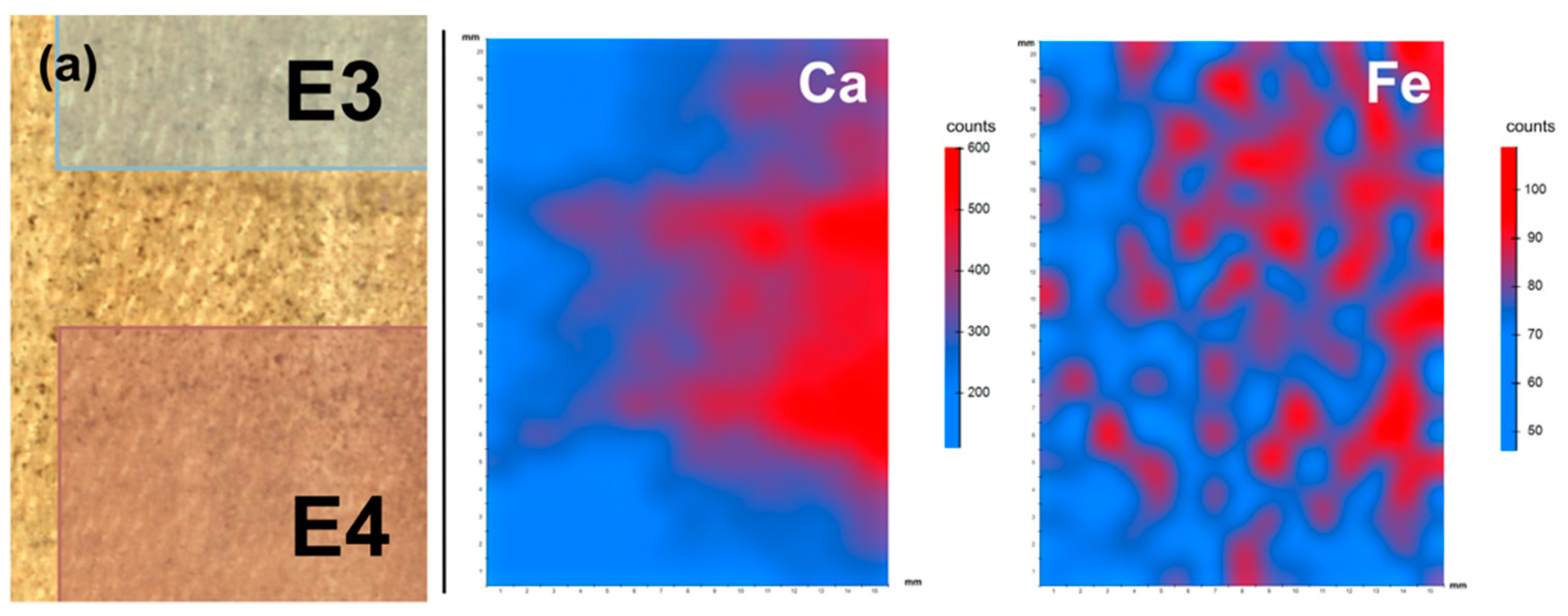
The EDXRF mapping mode [28] provided heat maps of the relative concentration of each element: the spatial distribution of elements and their abundances are shown, allowing easier qualitative observations of the cleaning action efficiency. Once a previous single-spot long-time-acquisition analysis is made to assess which elements are present in the dirt layer, the operator can follow up the cleaning by means of the mapping mode. According to its high signal, different calcium concentration areas are well distinguished. As shown in Figure 6, treated areas can be compared and different cleaning performance can be assessed. Different concentration areas are identifiable also for iron heat maps, whereas for the other detected elements counts are too few to allow an assessment of distributions. Other heat maps are shown in Figures S8–S10.

3.4. FTIR Spectroscopy

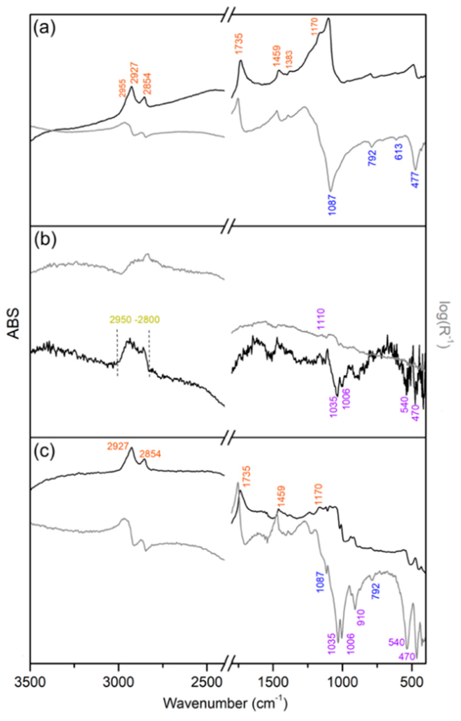
The pure soiling mixture was firstly analyzed in transmission mode in order to identify its characteristic bands (Figure A2, see Appendix A). In general, it was observed that some of these bands were detected in the dirty mock-ups also by the reflection FTIR technique. A further consideration concerns the reflection spectra collected on the varnished mock-ups (Figure 7a, Table S3 for assignments), where a relevant role was found to be played by the inverted—or Reststrahlen—silicate bands of the diatomaceous earth. This material, in fact, was employed in the varnish polishing procedure, within which it could likely be embedded during the mechanical process. Nevertheless, some of the resin and oil diagnostic bands can be discriminated in the spectra.
The following diagnostic sets of bands, attributed to dirt (1, 2) and varnish (3, 4), have been used to evaluate cleaning results:
  • broad ν(C–H) vibrations related to organic components (around 2900–2800 cm−1);
  • ν(Si–O) and δ(Si–O) vibrations related to the kaolin (1035, 1006, 540, 468, 396 cm−1);
  • sharp ν(C–H) vibrations due to colophony and linseed oil contributions (around 2900–2800 cm−1);
  • ν(Si–O) and δ(Si–O) vibrations related to the diatomaceous earth (1087, 792, 613, 477 cm−1).
In the maximum soil concentration areas, no emission related to the presence of varnish signals were detected and a broad absorbance signal around 2900–2800 cm−1 occurs (Figure 7b, Table 2 for assignments), attributed to the bulk reflection contribution of the dirt organic matrix [29]. Moreover, kaolin inverted bands dominated the spectral region at lower wavenumbers, hiding those of the diatomaceous earth that is diagnostic of cleaned surfaces. When the cleaning action was performed and the soil concentration lowered/approximated to zero, the spectrum profile changed with the re-emerging of varnish and diatomaceous earth signals.
The efficacy of the cleaning procedures—according to FTIR results—was estimated by their efficiency in removing organic components (i.e., peat moss, starch, gelatin, and carbon black) and kaolin. Three efficiency-grades were identified. The best cleaning score was assigned to emulsion cleaning (both E and A series), according to the detected bands at 2927 and 2854 cm−1 exactly corresponded to those of the varnish (Figure 7c). Also, the lower intensity varnish bands at 1735 and 1460 cm−1 returned to be present in the case of w/o emulsion, with no differences among times of application. A mild action of the cleaning corresponds to an intermediate result: the CH bands produced by the bulk and surface reflections—respectively of the dirt and the varnish—overlap, and it is difficult to distinguish these two contributions. Intermediate results were obtained after some cleaning treatments performed with the Tween 20 solution (A2) and synthetic saliva with Korean paper. If no change in the spectra occurred, then the cleaning was considered unsuccessful. In this category few treatments fell, in particular some treatments with synthetic saliva and Vulpex in agarose gel and most of the Tween 20 solution in agarose gel.
Concerning the silicate signals, kaolin Si–O bands never disappeared, and this would mean that kaolin is never totally removed by the adopted cleaning procedures. In some cases, also the diatomaceous earth bands were detected: in these spectra, more intense diatomaceous earth bands were set alongside less intense kaolin ones.
Table 3 summarizes the set of diagnostic analyses we are proposing to monitor the examined cleaning systems, with a focus on the parameters identified as remarkable for each analytical method. The results of cleaning performances are summarized in Table 4.

3.5. Evaluation of the Cleaning Systems Efficacy

The soiling mixture formed a complex layer in which several inorganic compounds are embedded in an organic matrix. This fact means that good interaction with the matrix was required before the cleaning solution could reach and interact with the inorganic compounds. This interaction was performed by two different cleaning modalities, which in the end resulted in the best cleaning results: w/o emulsion and Tween 20 water solution in agarose pad.
The w/o emulsion performed the best cleaning treatment. It was effective in removing most dirt compounds. Moreover, the treatment showed the best removal action in the case of short-time applications (2 min). This can be explained with the fact that w/o emulsion could interact both with lipophilic and hydrophilic materials due to its ambivalent nature and this is its advantage. The oily carrier of the emulsion could spread in the dirt organic matrix and soften it. In this way, the water micelles had a better chance to reach inorganic compounds and to enfold them in the micelles. On the other hand, a good cleaning action was performed also by Tween 20 water solution, especially in the form of agarose rigid gel. It removed efficiently organic components and after long-time applications started affecting also kaolin, Ca, and Fe compounds. The surfactant enhanced the wetting power of the solution thus allowing the spreading and the interaction with the dirt organic matrix, which was the first to be affected by the cleaning action. When the treatment was applied for a sufficient period of time, the inorganic compound removal was fostered by the softening of the organic matrix.
Synthetic saliva had a medium performance according to all techniques, in particular when applied with agarose gel pads that allowed a better surface contact. Efficiency in removing silicates grew with time of application, while the other dirt components were easily removed after short-time applications. This can be explained with the fact that they did not interact with chelators and were only embedded in the solution by the softening of the dirt matrix, thus requiring a certain amount of time as explained above. Vulpex solution was effective on dirt just when applied with agarose gel pads and acted particularly well in removing Si compounds. On the contrary, it seems to have no action on K and Fe compounds and a very low one on Ca compounds. Ca compounds removal occurred only after long time applications, when nevertheless also leftovers of the cleaning were found.
If we now compare carriers, a better cleaning performance was generally carried out by solution in agarose gel pads than with Korean paper. Agarose rigid gel allowed a closer contact than a Korean paper between the dirt surface and the cleaning solution and could carry much more solution, being equal to the contact surface. In this way, the dirt surface interacted constantly with a freshly new solution and more material could be removed. Agarose pad charged with different solutions promoted the removal of inorganic heavy compounds (calcium compounds, cement, umber) and carbon black. Another observation has to be pointed out: with agarose gel pads, dirt was uniformly—even if not totally—removed, while with the use of emulsion with a soft brush, which had the best cleaning results, the action was stronger but cleaned areas were not uniform.
After the treatment with o/w emulsion in agarose gel, sulfur on the cleaned surface was in higher concentration as compared with the previous measurements on the dirt surface. The sulfate ion is part of the SDS molecular structure and this fact suggests that residues of the cleaning were left on the surface.
Synthetic saliva and Vulpex residues were detected on mock-up I (K3, K4) and IV (A4). In both cases, an increase in potassium concentration on the cleaned surface was found after a long-time cleaning treatment. As regarding Vulpex, potassium is located in the hydrophilic side of the surfactant molecule. On contrary, K is absent in synthetic saliva formulation, therefore we supposed that it might be present as impurity. When the agar pad was left for a long time on the surface, too much liquid solution might have been released and left on it. These last considerations suggest that a subsequent wash of the surface with a swab and deionized water should be performed after each cleaning treatment to ensure the removal of any leftovers.

4. Conclusions

Surface cleaning treatments are part of the procedures for the preservation of ancient musical instruments. In this work, we proposed a set of non-invasive analyses that can be performed during the conservation treatment in order to monitor the artifact surface cleaning. Image analysis and punctual spectroscopy were used and specific diagnostic features were identified for each technique.
Visible imaging was able to give a first reference to assess the efficacy of the cleaning systems in terms of ability in restoring the original color appearance. Quantitative colorimetric analysis of visible images was used to accurately estimate the color change. NIR imaging assessed carbon black removal, whereas UVIFL imaging was particularly efficient in detecting non-fluorescent compounds (cement, lime, silica, and iron oxides).
EDXRF and reflection FTIR spectroscopies gave complementary information about dirt compounds, which supported and complemented imaging analyses. Calcium and iron signals were the highest ones for EDXRF spectroscopy. They carried information about the cement, lime, and umber pigment presence. A decrease of their characteristic elemental peaks was correlated with the cleaning action of the corresponding materials. Other elements (K, Si, S) gave information about leftovers or particularly selective cleaning actions. In the considered set-up, EDXRF gave little information about light elements like silicon, but more evidence about silicates was obtained thanks to IR spectroscopy. Varnish and diatomaceous earth vibrational bands characterized the varnish surface and the reappearance of their signals shows that the dirty layer has been at least partially removed. As regarding the soiling mixture over the mock-ups, FTIR spectroscopy identified signals about silicates (kaolin) and organic compounds (peat moss, starch, and gelatin).
Some cleaning systems were tested and monitored with the mentioned analytical techniques. The w/o emulsion performed the best removal action both on organic and inorganic dirt compounds. Depending on which components restorers want to remove, Tween 20 in water solution and synthetic saliva are able to perform a basic but efficient cleaning. The worst cleaning action is related to Vulpex in water solution.
The application of the same analytical protocol on aged mock-ups is currently part of a following research project and, at any event, is mandatory before dealing with the original surface of ancient musical instruments.
Deeper knowledge about the dirt composition deposited on musical instruments should be also achieved, in order to prepare and perform more selective cleaning. Further micro-analyses performed on samples collected from dirty musical instruments surfaces and the study of their conservation environment will give more precise information about the composition of dirt, leading in the next future to develop better analytical strategies and suitable protocols for evaluating the efficiency of the cleaning processes for bowed string musical instruments.

Supplementary Materials

The following are available online at https://www.mdpi.com/2079-6412/11/2/150/s1, Figure S1: Chromatic coordinates (right graphs) and lightness (left graph) calculated from visible images from varnished reference mock-up (red) and before (blue) and after (yellow) the cleaning performed on mock-up I, Figure S2: Lightness (left graph) and chromatic coordinates (right graph) calculated from visible images from varnished reference mock-up (red) and before (blue) and after (yellow) the cleaning performed on mock-up II, Figure S3: Lightness (left graph) and chromatic coordinates (right graph) calculated from visible images from varnished reference mock-up (red) and before (blue) and after (yellow) the cleaning performed on mock-up III, Figure S4: Lightness (left graph) and chromatic coordinates (right graph) calculated from visible images from varnished reference mock-up (red) and before (blue) and after (yellow) the cleaning performed on mock-up IV, Figure S5: Multispectral imaging of mock-up I: VIS (a), UVIFL (b), NIR (c) and IRFC (d), Figure S6: Multispectral imaging of mock-up III: VIS (a), UVIFL (b), NIR (c) and IRFC (d), Figure S7: Multispectral imaging of mock-up IV: VIS (a), UVIFL (b), NIR (c) and IRFC (d), Figure S8: EDXRF heat maps on a selected area of mock-up I. Higher and lower relative concentrations of each characteristic element are presented respectively in red and blue colors. Stitch visible image (a) of the area (15 mm × 15 mm) considered for the XRF mapping, Figure S9: XRF heat maps on a selected area of mock-up II. Higher and lower relative concentrations of each characteristic element are presented respectively in red and blue colors. Stitch visible image (a) of the area (15 mm × 20 mm) considered for the XRF mapping, Figure S10: XRF heat maps on a selected area of mock-up IV. Higher and lower relative concentrations of each characteristic element are presented respectively in red and blue colors. Stitch visible image (a) of the area (15 mm × 20 mm) considered for the XRF mapping, Table S1: Color differences between (L*, a*, b*) values of the same areas of each mock-ups before and after the cleaning treatment, Table S2: Normalized net area count average and relative SDOM of each emission peak (Kα) identified in EDXRF spectrum, Table S3: Reflection FTIR wavenumber values, and their assignment [5,6], of the bands identified in dried oil-colophony varnished mock-ups.

Author Contributions

Conceptualization, I.C., T.R. and M.G.; validation, M.M., T.R., C.I. and N.G.L.; formal analysis, I.C.; investigation, I.C.; methodology, I.C., M.G. and T.R.; data curation, I.C.; writing—original draft preparation, I.C.; writing—review and editing, T.R., M.G., C.C. and C.I.; visualization, I.C.; supervision, T.R. and M.G. All authors have read and agreed to the published version of the manuscript.

Funding

This research did not receive any specific grant from funding agencies in the public, commercial, or not-for-profit sectors.

Institutional Review Board Statement

Not applicable.

Informed Consent Statement

Not applicable.

Data Availability Statement

Data is contained within the article or supplementary material.

Acknowledgments

The authors would like to thank Professor Curzio Merlo (Laboratorio di Diagnostica e analisi chimico-fisiche of Scuola di Restauro CR. Forma, Cremona, Italy) for his precious collaboration.

Conflicts of Interest

The authors declare no conflict of interest.

Appendix A

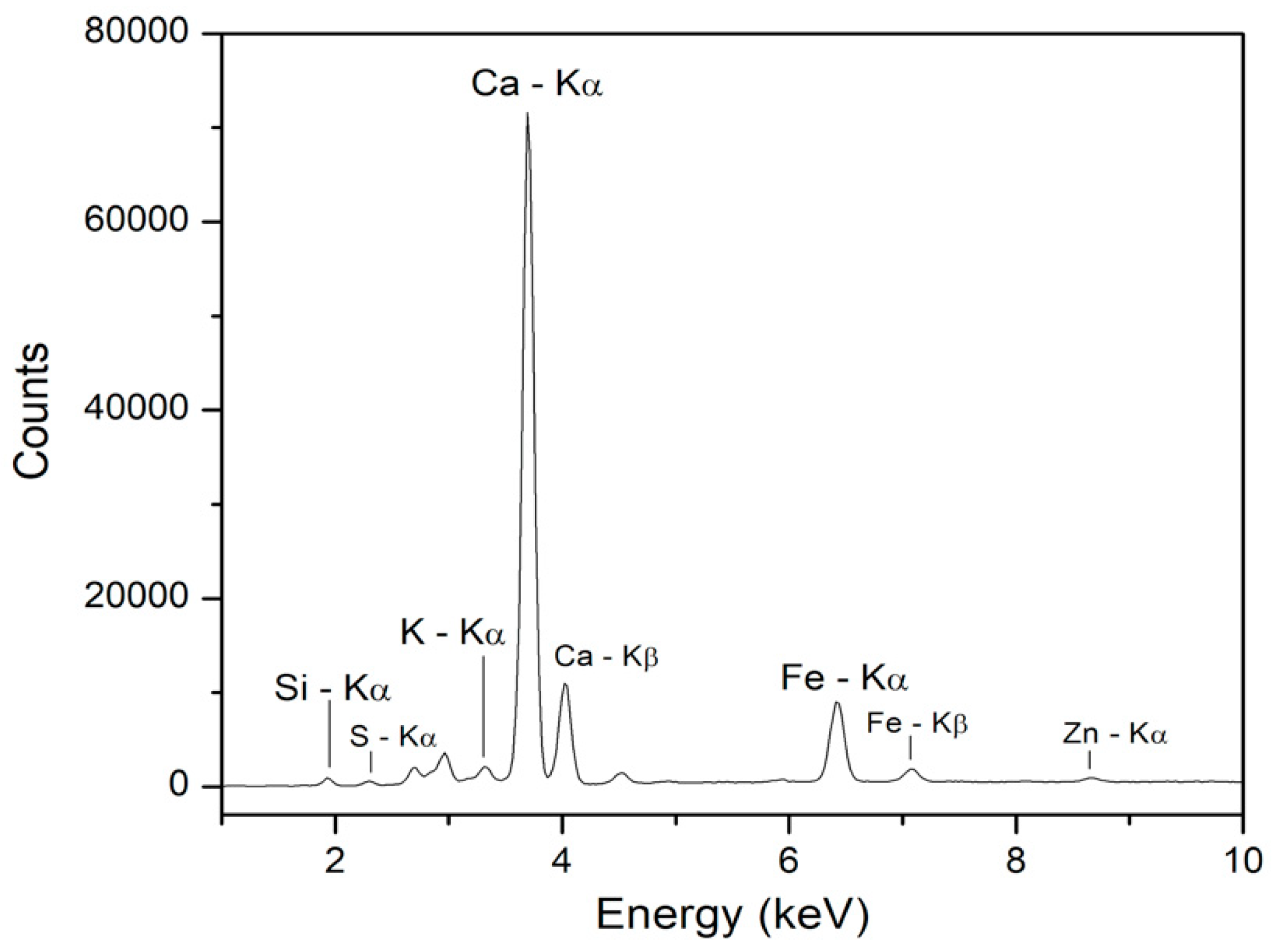
In Figure A1: the dry fraction of the pure soiling mixture XRF spectrum is displayed. In the chart, detected elements are reported: calcium (Ca), iron (Fe), potassium (K) and traces of zinc (Zn), sulphur (S) and silicon (Si). The main peaks are related to Ca and secondly to Fe, then potassium (K) is found. Signals of Zn, S and Si are weak. Regarding S and Si, they are underestimated due to their low Z (atomic number). What stands out in the table at first sight is that Ca peak area is about ten times higher than Fe one. This implies a total predominance of calcium in the dirty mixture applied on the mock-ups.
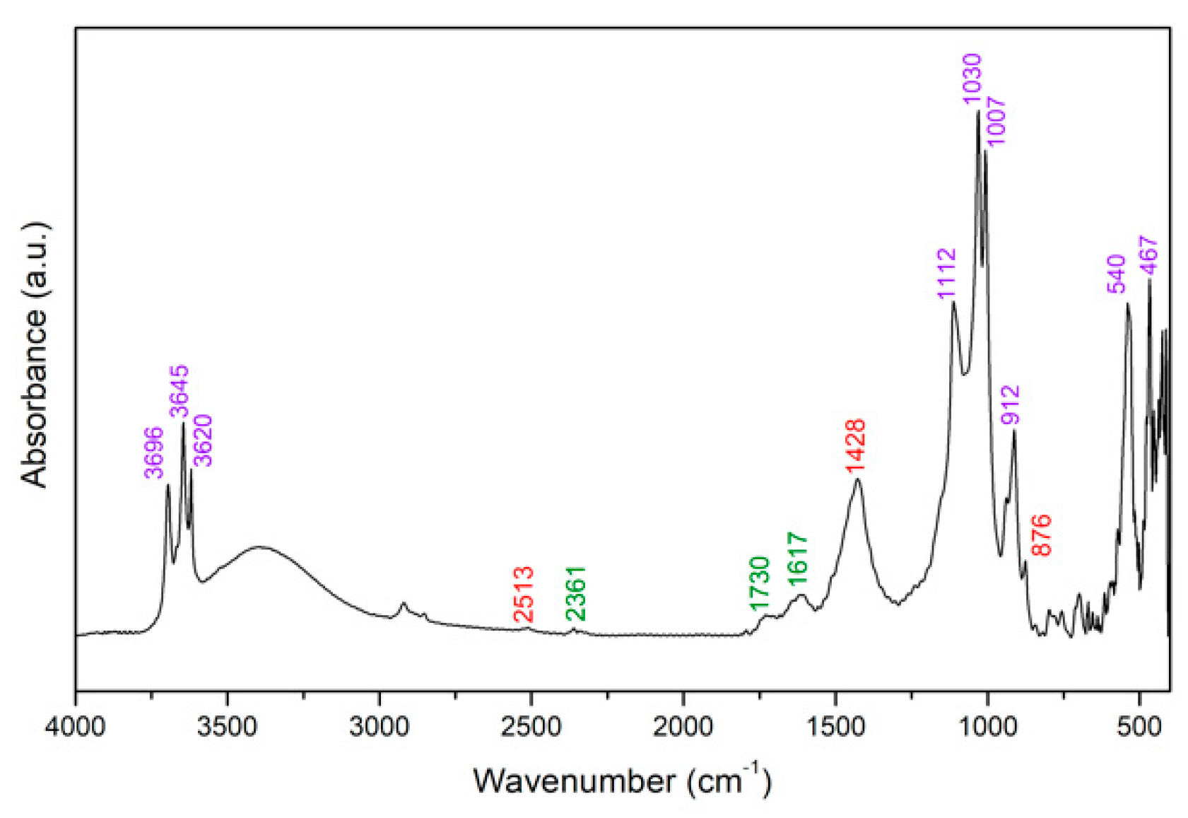
As regards FTIR analysis, the marker bands of soiling mixture are associated to the various ingredients that compose it: kaolin (ν(O–H) at 3696, 3645 and 3620 cm−1, δ(O–H) at 938 cm−1, longitudinal ν(Si–O) at 1112 cm−1, in–plane δ(Si–O) at 1030 and 1007 cm−1, δ(AlAlOH) at 912 cm−1, δ(Si–O) at 798, 756 and 697 cm−1, δ(Al–O–Si) at 540 cm−1, δ(Si–O–Si) at 470 cm−1) [1], calcium carbonate (1793, 1428 and 876 cm−1) [2] from calcium hydroxide reaction with ambiental CO2, peat moss (ν(C–O) at 1730 and 1617 cm−1, ν(C–O) and δ(C–O) at 1153 cm−1, C–H at 843, 820 cm−1) [3], gelatin (C–H at 2361 cm-1), cement (at 2513, 1793, 1428 and 876 cm−1). Other bands are found at 2920 and 2854 cm−1 and a broad one between 3750 and 2950 cm−1, which are generated by vibrational modes of organic components of dirt. The spectra of soiling mixture and of pure soiling ingredients were collected with the spectrometer NicoletTM iNTM10 Infrared Microscope (Thermo Scientific) in transmission mode. Chemical composition of pure components of the soiling mixture were analyzed by means of KBr pellets (standard pressure, room temperature). The assignment of dirt signals was made for comparison with the transmission spectra of single soil components, then confirmed by literature.
Figure A1. EDXRF spectrum of the dry part of soiling mixture.
Coatings 11 00150 g0a1
Figure A2. FTIR spectrum of the soiling mixture collected in transmission mode. Marker bands and relative wavenumber values of dirt components (kaolin in purple, cement/calcium carbonate in red, organic components in green) are highlighted.
Coatings 11 00150 g0a2

References

  1. Rhyne, C.S. Clean art? J. Am. Inst. Conserv. 2006, 45, 165–170. [Google Scholar] [CrossRef]
  2. Gritt, S. The removal of patina. In New Insights into the Cleaning of Paintings, Proceedings of the Cleaning 2010 International Conference, Universidad Politecnica de Valencia and Museum Conservation Institute; Smithsonian Institution: Washington, DC, USA, 2013. [Google Scholar]
  3. Camuffo, D. Microclimate for Cultural Heritage: Measurement, Risk Assessment, Conservation, Restoration, and Maintenance of Indoor and Outdoor Monuments; Elsevier: Amsterdam, The Netherlands, 2019; ISBN 978-0-444-64107-6. [Google Scholar]
  4. Rovetta, T.; Invernizzi, C.; Licchelli, M.; Cacciatori, F.; Malagodi, M. The elemental composition of stradivari’s musical instruments: New results through non-invasive EDXRF analysis. X-ray Spectrom. 2018, 47, 159–170. [Google Scholar] [CrossRef]
  5. Holakooei, P.; Abed Esfahani, A. Conservation unit museums and galleries commission. In The Science For. Conservators Series: Volume 2: Cleaning; Routledge: Abingdon, UK, 2005; ISBN 978-1-134-90961-2. [Google Scholar]
  6. Wolbers, R.C. the use of a synthetic soiling mixture as a means for evaluating the efficacy of aqueous cleaning materials on painted surfaces. Conserv. Restaur. Des. Biens Cult. Rev. De L’araafu 1992, 4, 22–29. [Google Scholar]
  7. Florio, P.A.; Mersereau, E.P. Control of appearance changes due to soiling: The mechanism, measurement, and reduction of soiling changes in carpet during use. Text. Res. J. 1955, 25, 641–649. [Google Scholar] [CrossRef]
  8. Wolbers, R. Cleaning Painted Surfaces: Aqueous Methods; Archetype Publication: London, UK, 2000; ISBN 978-1-873132-36-4. [Google Scholar]
  9. Cavaleri, T.; Fiocco, G.; Rovetta, T.; Malagodi, M.; Piccirillo, A.; Pisani, M.; Zucco, M.; Gargano, M. A new imaging method of fluorescence induced by multispectral UV for studying historical musical instruments coatings. In UV-Vis Luminescence Imaging Techniques; López, L.F., Stols-Witlox, M., Picollo, M., Eds.; Editorial Universitat Politècnica de València: Valencia, Spain, 2020. [Google Scholar] [CrossRef] [Green Version]
  10. Signorini, E. Surface cleaning of paintings and polychrome objects in Italy: The last 15 years. In New Insights into the Cleaning of Paintings, Proceedings of the Cleaning 2010 International Conference, Universidad Politecnica de Valencia and Museum Conservation Institute; Smithsonian Institution: Washington, DC, USA, 2013. [Google Scholar]
  11. Cremonesi, P. L’uso Dei Tensioattivi e Chelanti Nella Pulitura Di Opere Policrome; Il Prato: Padova, Italy, 2004; ISBN 88-87243-84-0. [Google Scholar]
  12. Wennerström, H. Micelles. physical chemistry of surfactant association. Phys. Rep. 1979, 52, 1–86. [Google Scholar] [CrossRef]
  13. Baglioni, P.; Berti, D.; Bonini, M.; Carretti, E.; Dei, L.; Fratini, E.; Giorgi, R. Micelle, microemulsions, and gels for the conservation of cultural heritage. Adv. Colloid Interface Sci. 2014, 205, 361–371. [Google Scholar] [CrossRef] [PubMed]
  14. Invernizzi, C.; Daveri, A.; Rovetta, T.; Vagnini, M.; Licchelli, M.; Cacciatori, F.; Malagodi, M. A multi-analytical non-invasive approach to violin materials: The case of Antonio Stradivari “Hellier” (1679). Microchem. J. 2016, 124, 743–750. [Google Scholar] [CrossRef]
  15. Poggialini, F.; Fiocco, G.; Campanella, B.; Legnaioli, S.; Palleschi, V.; Iwanicka, M.; Targowski, P.; Sylwestrzak, M.; Invernizzi, C.; Rovetta, T.; et al. Stratigraphic analysis of historical wooden samples from ancient bowed string instruments by laser induced breakdown spectroscopy. J. Cult. Herit. 2020, 44, 275–284. [Google Scholar] [CrossRef]
  16. Fiocco, G.; Rovetta, T.; Malagodi, M.; Licchelli, M.; Gulmini, M.; Lanzafame, G.; Zanini, F.; Lo Giudice, A.; Re, A. Synchrotron radiation micro-computed tomography for the investigation of finishing treatments in historical bowed string instruments: Issues and perspectives. Eur. Phys. J. Plus 2018, 133, 525. [Google Scholar] [CrossRef]
  17. Weththimuni, M.L.; Canevari, C.; Legnani, A.; Licchelli, M.; Malagodi, M.; Ricca, M.; Zeffiro, A. Experimental characterization of oil-colophony varnishes: A preliminary study. Int. J. Conserv. Sci. 2016, 2, 813–826. [Google Scholar]
  18. Robson, J. Burnishing Varnish to a Fine Polish. Strad 2007, 64–67. [Google Scholar]
  19. Cremonesi, P. Rigid gels and enzyme cleaning. New Insights into the Cleaning of Paintings: Proceedings from the Cleaning 2010 International Conference Universidad Politecnica de Valencia and Museum Conservation Institute; Smithsonian Institution: Washington, DC, USA, 2013. [Google Scholar]
  20. Campani, E. L’uso di Agarosio e Agar per la Preparazione di gel Rigidi = Use of Agarose and Agar for Preparing Rigid Gels; Il Prato: Padova, Italy, 2007; ISBN 978-88-89566-65-7. [Google Scholar]
  21. Gorel, F. Assessment of agar gel loaded with micro-emulsion for the cleaning of porous surfaces. Ceroart. Conserv. Expo. Restaur. D’objets D’art 2010. [Google Scholar] [CrossRef]
  22. Rasband, W.S. ImageJ.; U.S. National Institutes of Health: Bethesda, MD, USA, 1997. [Google Scholar]
  23. CIE ILV CIE Publication S 017/E:2011. ILV: International Lighting Vocabulary. CIE Central Bureau, Kegelgasse 27, A-1030 Vienna, Austria (2011). Available online: http://eilv.cie.co.at/termlist (accessed on 2 September 2020).
  24. Oleari, C. Standard Colorimetry: Definitions, Algorithms and Software; John Wiley & Sons: Hoboken, NJ, USA, 2016; ISBN 978-1-118-89444-6. [Google Scholar]
  25. Luo, M.R.; Cui, G.; Rigg, B. The Development of the CIE 2000 colour-difference formula: CIEDE2000. Color. Res. Appl. 2001, 26, 340–350. [Google Scholar] [CrossRef]
  26. Bonizzoni, L.; Canevari, C.; Galli, A.; Gargano, M.; Ludwig, N.; Malagodi, M.; Rovetta, T. A multidisciplinary materials characterization of a Joannes Marcus Viol (16th century). Herit. Sci. 2014, 2, 15. [Google Scholar] [CrossRef] [Green Version]
  27. Gargano, M.; Ludwig, N.; Poldi, G. A New methodology for comparing IR reflectographic systems. Infrared Phys. Technol. 2007, 49, 249–253. [Google Scholar] [CrossRef]
  28. Rovetta, T.; Invernizzi, C.; Fiocco, G.; Albano, M.; Licchelli, M.; Gulmini, M.; Alf, G.; Fabbri, D.; Rombolà, A.G.; Malagodi, M. The case of Antonio Stradivari 1718 Ex-San Lorenzo Violin: History, restorations and conservation perspectives. J. Archaeol. Sci. Rep. 2019, 23, 443–450. [Google Scholar] [CrossRef] [Green Version]
  29. Griffiths, P.R.; de Haseth, J.A. Fourier Transform. Infrared Spectrometry; John Wiley & Sons: Hoboken, NJ, USA, 2007. [Google Scholar]
  30. Invernizzi, C.; Fichera, G.V.; Licchelli, M.; Malagodi, M. A non-invasive stratigraphic study by reflection FT-IR spectroscopy and UV-induced fluorescence technique: The case of historical violins. Microchem. J. 2018, 138, 273–281. [Google Scholar] [CrossRef]
  31. Invernizzi, C.; Daveri, A.; Vagnini, M.; Malagodi, M. Non-invasive identification of organic materials in historical stringed musical instruments by reflection infrared spectroscopy: A methodological approach. Anal. Bioanal. Chem. 2017, 409, 3281–3288. [Google Scholar] [CrossRef] [PubMed]
  32. Erasmus, E. The influence of thermal treatment on properties of Kaolin. Hem. Ind. 2016, 70, 595–601. [Google Scholar] [CrossRef]
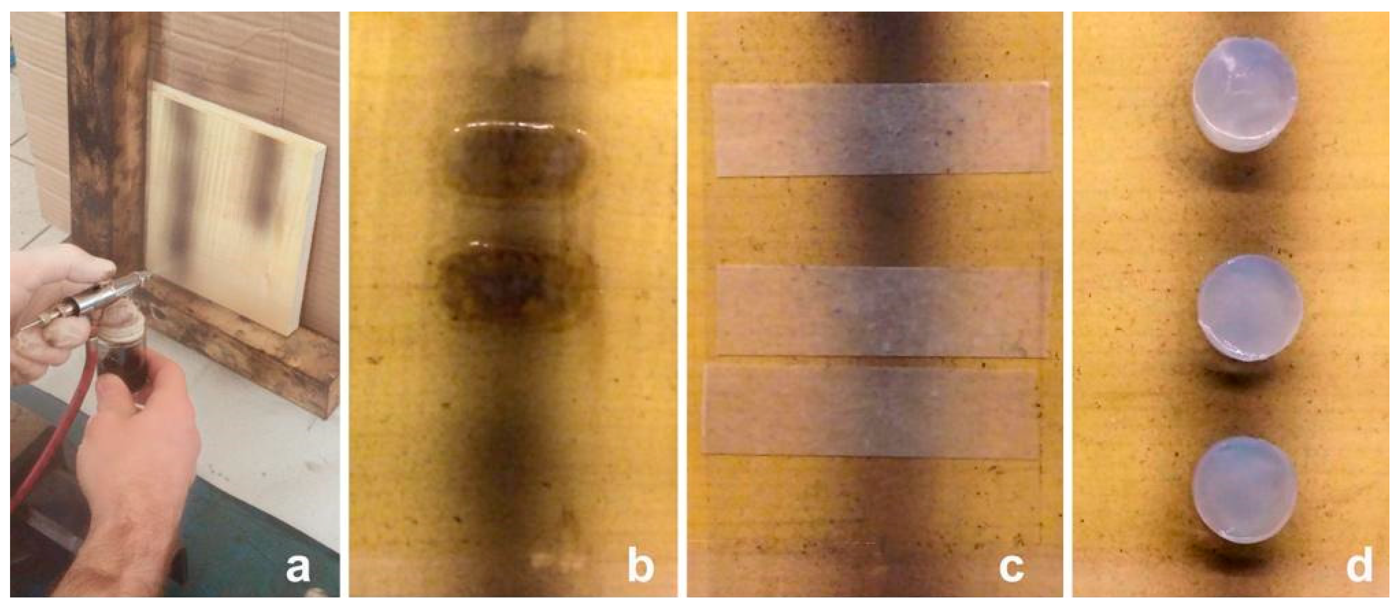
Figure 1. Soil was spread by airbrush along with two columns on each mock-up (a). Airbrushing allowed for depositing matter in a gradient from the center to the edge. Cleaning tests performed using different delivery systems: w/o emulsion (b), Korean paper (c), agarose rigid gel pads (d).
Coatings 11 00150 g001
Figure 2. Stereomicroscopy: Transition zone between dirt and varnished surface, direct light (a) and grazing light, from right to left (b); macro photography of a squared cleaned portion on the dirty surface, obtained with the use of 5-min application w/o emulsion (c).
Coatings 11 00150 g002
Figure 3. visible imaging (VIS) (a), ultraviolet-induced visible fluorescence (UVIFL) (b), near-infrared (NIR) (c), and infrared false-color imaging (IRFC) (d).
Coatings 11 00150 g003
Figure 4. Lightness (left graph) and chromatic coordinates (right graph) calculated from visible images for varnished reference mock-up (black) and before and after the cleaning performed on mock-up II with w/o emulsion and different application times (E1–E4). Standard deviations of the mean are ±0.1 for the L* values and ±0.01 for the a* and b* values.
Coatings 11 00150 g004
Figure 5. Stacked EDXRF spectra collected on mock-ups at the different stages of wood preparation (red), varnishing (orange), soiling (black), and cleaning (green) processes. The spectrum collected on wood preparation with potassium caseinate is also reported since signals of this layer can be detected in XRF analysis on upper layers. The selected cleaned area for the exemplum is E1 on mock-up II. Small differences can be observed between the stages before (red line) and after (orange line) varnishing procedure. P, S, K, Ca, Fe are detected on the wood preparation; their signals get weaker when the varnish layer is superimposed since the organic matrix traps photons. In the varnish layer curve, we also find a new peak that corresponds to Si and can be related to the presence of diatomaceous earth used in polishing procedure, which may be caught by soft varnish.
Coatings 11 00150 g005
Figure 6. XRF heat maps on a selected area of mock-up III. Higher and lower relative concentrations of each characteristic element are presented respectively in red and blue colors. Stitch visible image (a) of the area (15 mm × 20 mm) considered for the XRF mapping. Calcium is well removed in the longer application (E4 – 10 min) and partially in the 5-min one (E3). Iron is slightly affected only by the E4 treatment.
Coatings 11 00150 g006
Figure 7. Reflection FTIR spectra in pseudo-absorbance (gray line) and after Kramers-Kronig Transformation (KKT, black line) of mock-up surfaces: varnish (a); dirty varnish (b); spot on mock-up II that underwent two-minute application of w/o emulsion – E1 treatment (c). Marker bands and relative wavenumber values of varnish (orange), diatomaceous earth (blue), kaolin (purple) and organic compounds - may be the sum of individual contributions of organic dirt and varnish - (green) are highlighted. Dotted lines outline the volume reflection contribution of the dirt organic compounds.
Coatings 11 00150 g007
Table 1. Details of the tested cleaning procedures, with the mock-up reference number.
Mock-Up Ref. NumberCleaning SystemsComponentsCleaning AgentDelivery System
ISynthetic saliva Ammonium and Sodium Citrate tribasic solution + mucin (protein, surfactant)—CTS restaurochelating molecules, mucin (surfactant)Korean paper
Chelating solutionAmmonium and Sodium Citrate tribasic solution of synthetic saliva—CTS restaurochelating molecules, wateragarose gel
IIWater in oil (w/o) emulsionSurfactant: BrijTM 30 (polyethylene glycol dodecyl ether)—Sigma-Aldrich; oil: isooctane
[85% isooctane, 10% dH2O, 5% surfactants]
water micellesoil
Oil in water (o/w) emulsion [21]main surfactant: SDS (sodium dodecyl sulphate)
co-surfactant: 1-pentanol; oil: isooctane
[85% dH2O, 5% isooctane, 10% surfactants]
oil micelleswater/agarose gel
IIINon-ionic surfactant 2% v/v water solution TweenTM 20 (polyethylene glycol sorbitan monolaurate)—Sigma-Aldrichwater micellesagarose gel and Korean paper
IVAnionic surfactant 2% v/v water solution Vulpex 1 (Potassium Methyl-cyclohexyl oleate and Methyl Cyclohexanol.)—Picreator Enterprises Ltd.water micellesagarose gel and Korean paper
1 Vulpex is a commercial soap whose use is spread among violin restorers.
Table 2. Assignment of the infrared bands [30,31,32] identified on the dirt layer on varnished mock-ups.
WavenumberBand ShapeAssignmentMaterial Attribution
2900–2800 cm−1 (m)Absorptionν C–HOrganic
1035 (s)Invertedνas Si–OKaolin
1006 (s)Invertedνas Si–OKaolin
540 (m)Invertedδ Al–O–SiKaolin
468 (m)Invertedin-plane δ Si–OKaolin
396 (m)Invertedin-plane δ Si–O–SiKaolin
Table 3. The table relates each non-invasive analysis with the corresponding parameters that allow to monitor the cleaning procedure.
AnalysisModeObservation
StereomicroscopyDirect and grazing lightPreliminary surface check, granulometry of dirt and surface morphology
Energy Dispersive
X-ray fluorescence spectroscopy (EDXRF)
Punctual and mapping mode
  • Removal of elements that characterize dirt: Ca (kaolin, cement), Fe (umber, cement), K (peat moss, kaolin), Si (kaolin, silica, cement), S (widespread)
  • Presence of elements attributable to residuals of cleaning
Reflection Fourier transformed infrared reflectance (FTIR) spectroscopyPunctual mode
  • Decrease in the intensity of vibrational bands related to inorganic (kaolin) components of dirt
  • Change in the shape of bands related to organic components (peat moss, starch and gelatin) of dirt
  • Increase in the intensity of vibrational bands related to resin and oil (varnish components) and diatomaceous earth (polish)
Multispectral imaging—color comparisons were both qualitative by image observation and quantitative by colorimetric extracted dataVisible imaging (VIS)Surface color turns towards original varnish one
Ultraviolet-induced fluorescence imaging (UVIFL)
  • Varnish fluorescence turns up when soil is removed.
  • Original fluorescence color change due to interaction with varnish surface of the cleaning or fluorescent leftovers
Near-infrared imaging (NIR)Removal of carbon black
Table 4. The table summarizes all the treatment efficiency according to the employed analytical techniques. Results were divided into four groups according to specific ranges, discussed in each technique paragraph: X indicates that the cleaning was unsuccessful; ✓, ✓✓, ✓✓✓ correspond respectively to low, intermediate and high cleaning performances.
-EDXRFFTIRVIS Imaging ColorimetryUVIFL ImagingNIR ImagingNotes
Cleaning TreatmentDelivery SystemSiSKCaFeLeftoversKaolinOrganicReappearing of fl.Change in fl. Color
Synthetic salivaA✓✓✓✓✓✓ ✓✓-X✓✓orangeEfficacy grows with time of application in the removal of silicate.
K✓✓✓✓✓✓✓✓XK leftovers for 5-h treatment✓✓✓✓XX-XEfficacy grows with time of application in the removal of silicate.
EmulsionA (o/w)✓✓X✓✓✓✓✓S leftovers✓✓✓✓✓✓✓✓✓✓✓not observed✓✓-
E (w/o)✓✓X✓✓✓✓✓-✓✓✓✓✓✓✓✓not observed✓✓✓Efficacy grows with time of application in the removal of silicate.
Tween 20 2% v/v solutionA✓✓XX✓✓✓✓-XX✓✓✓✓not observed✓✓Efficacy grows with time of application.
K✓✓XK leftovers for treatments longer than 1 minX✓✓not observed-
Vulpex 2% v/v solutionAX✓✓X✓✓XK leftovers for 5-h treatmentXXX-XA slight cleaning result is observed after the long-time treatment.
K✓✓XXX-XX-X-
Publisher’s Note: MDPI stays neutral with regard to jurisdictional claims in published maps and institutional affiliations.