
Effect of High-Speed Powder Feeding on Microstructure and Tribological Properties of Fe-Based Coatings by Laser Cladding

Abstract
:1. Introduction
2. Experiment
3. Results and discussion
3.1. Microstructure
3.2. Phase Analysis
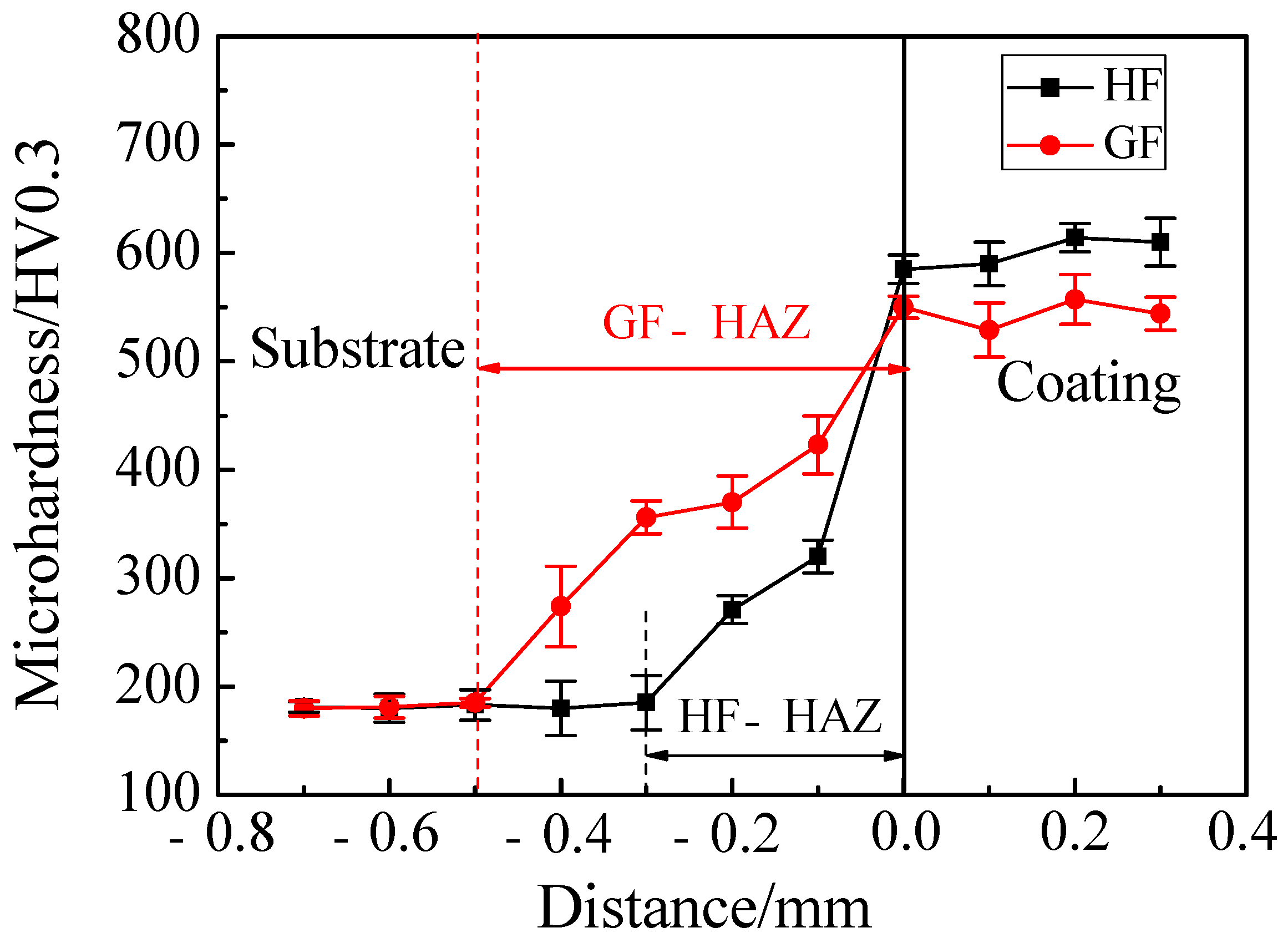
3.3. Microhardness Analysis
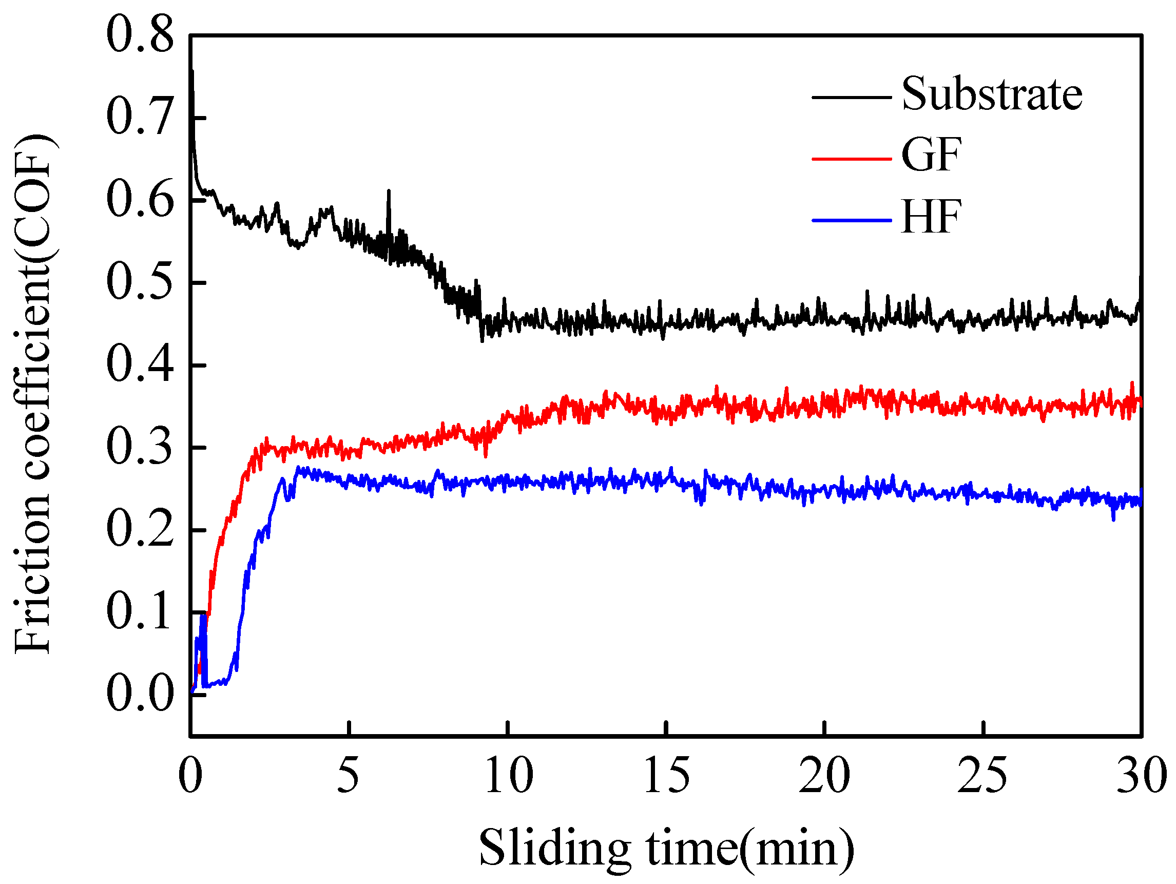
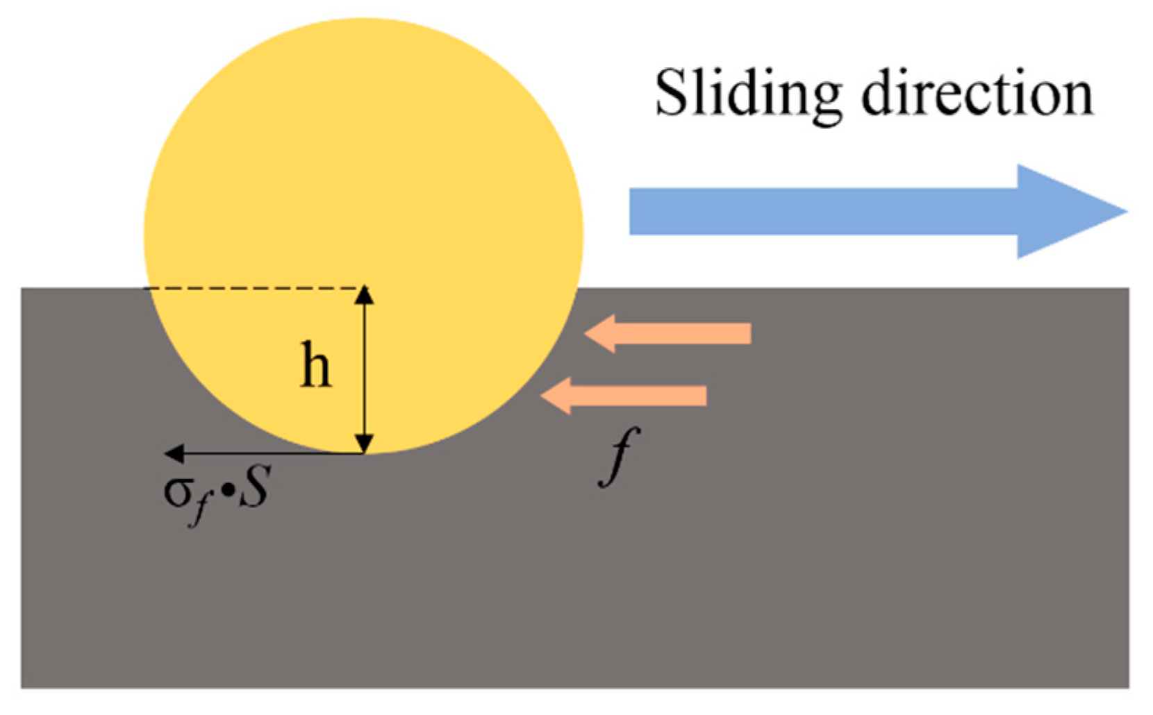
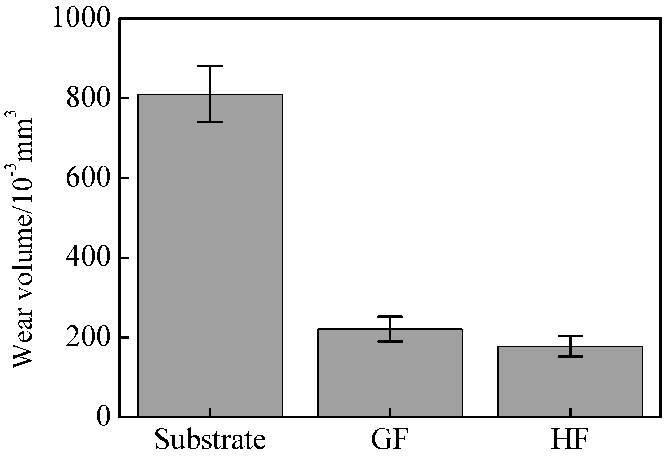
3.4. Tribological Performance Analysis of Coating and Substrate
4. Conclusions
Author Contributions
Funding
Institutional Review Board Statement
Informed Consent Statement
Data Availability Statement
Conflicts of Interest
References
- Collard-Wexler, A.; De Loecker, J. Reallocation and Technology: Evidence from the U.S. Steel Industry. Am. Econ. Rev. 2013, 105, 131–171. [Google Scholar] [CrossRef] [Green Version]
- Zhang, H.; Hong, X. An overview for the utilization of wastes from stainless steel industries. Resour. Conserv. Recycl. 2011, 55, 745–754. [Google Scholar]
- Alexeev, A.A.; Bolshev, K.N.; Ivanov, V.A.; Syromyatnikova, A.S.; Kovalenko, A.N. Experimental determination of crack velocities in steel. Procedia Struct. Integr. 2020, 30, 1–5. [Google Scholar] [CrossRef]
- Tiberti, G.; Trabucchi, I.; AlHamaydeh, M.; Minelli, F.; Plizzari, G.A. Crack development in steel-fibre-reinforced concrete members with conventional rebars. Mag. Concr. Res. 2019, 71, 599–610. [Google Scholar] [CrossRef]
- Yang, Y.W.; Fu, H.G.; Ju, J.; Lei, Y.P.; Zhu, L.L.; Jiang, L. Phase diagram caGFulation and analyze on cast high vanadium wear-resistant alloy. Metall. Res. Technol. 2017, 114, 314. [Google Scholar] [CrossRef]
- Gong, J.; Zhang, D.; Liu, C.; Zhao, Y.; Hu, P.; Quan, W. Optimization of electro-hydraulic energy-savings in mobile machinery. Autom. Constr. 2019, 98, 132–145. [Google Scholar] [CrossRef]
- Wang, D.; Tian, Z.; Wang, S.; Shen, L.; Liu, Z. Microstructural characterization of Al2O3–13 wt.% TiO2 ceramic coatings prepared by squash presetting laser cladding on GH4169 superalloy. Surf. Coat. Technol. 2014, 254, 195–201. [Google Scholar] [CrossRef]
- Baldridge, T.; Poling, G.; Foroozmehr, E.; Kovacevic, R.; Metz, T.; Kadekar, V.; Gupta, M.C. Laser cladding of Inconel 690 on Inconel 600 superalloy for corrosion protection in nuclear applications. Opt. Lasers Eng. 2013, 51, 180–184. [Google Scholar] [CrossRef]
- Wang, K.; Du, D.; Liu, G.; Chang, B.; Ju, J.; Sun, S.; Fu, H. Microstructure and property of laser clad Fe-based composite layer containing Nb and B4C powders. J. Alloys Compd. 2019, 802, 373–384. [Google Scholar] [CrossRef]
- Lei, J.; Shi, C.; Zhou, S.; Gu, Z.; Zhang, L.C. Enhanced corrosion and wear resistance properties of carbon fiber reinforced Ni-based composite coating by laser cladding. Surf. Coat. Technol. 2018, 334, 274–285. [Google Scholar] [CrossRef] [Green Version]
- Luo, X.; Yao, Z.; Zhang, P.; Gu, D.; Chen, Y. Laser Cladding Fe-Al-Cr Coating with Enhanced Mechanical Properties. J. Wuhan Univ. Technol.-Mater. Sci. Ed. 2019, 34, 1197–1204. [Google Scholar] [CrossRef]
- Tian, J.; Xu, P.; Chen, J.; Liu, Q. Microstructure and phase transformation behaviour of a Fe/Mn/Si/Cr/Ni alloy coating by laser cladding. Opt. Lasers Eng. 2019, 122, 97–104. [Google Scholar] [CrossRef]
- Rahman Rashid, R.A.; Javed, M.A.; Barr, C.; Palanisamy, S.; Matthews, N.; Dargusch, M.S. Effect of in situ tempering on the mechanical, microstructural and corrosion properties of 316L stainless steel laser-cladded coating on mild steel. Int. J. Adv. Manuf. Technol. 2021, 117, 2949–2958. [Google Scholar] [CrossRef]
- Fesharaki, M.N.; Shoja-Razavi, R.; Mansouri, H.A.; Jamali, H. Microstructure investigation of Inconel 625 coating obtained by laser cladding and TIG cladding methods. Surf. Coat. Technol. 2018, 353, 25–31. [Google Scholar] [CrossRef]
- Yang, S.; Phung, T.A. Microstructure and properties of Cu/TiB2 wear resistance composite coating on H13 steel prepared by in-situ laser cladding. Opt. Laser Technol. 2018, 108, 480–486. [Google Scholar]
- Li, Y.; Dong, S.; Yan, S.; Li, E.; Liu, X.; He, P.; Xu, B. Deep pit repairing of nodular cast iron by laser cladding NiCu/Fe-36Ni low-expansion composite alloy. Mater. Charact. 2019, 151, 273–279. [Google Scholar] [CrossRef]
- Zhu, Y.; Yang, Y.; Mu, X.; Wang, W.; Yao, Z.; Yang, H. Study on wear and RCF performance of repaired damage railway wheels: Assessing laser cladding to repair local defects on wheels. Wear 2019, 430–431, 126–136. [Google Scholar] [CrossRef]
- Rashid, R.R.; Nazari, K.A.; Barr, C.; Palanisamy, S.; Orchowski, N.; Matthews, N.; Dargusch, M.S. Effect of laser reheat post-treatment on the microstructural characteristics of laser-cladded ultra-high strength steel. Surf. Coat. Technol. 2019, 372, 93–102. [Google Scholar] [CrossRef]
- Cao, Y.; Farouk, N.; Taheri, M.; Yumashev, A.V.; Bozorg SF, K.; Ojo, O.O. Evolution of solidification and microstructure in laser-clad IN625 superalloy powder on GTD-111 superalloy. Surf. Coat. Technol. 2021, 412, 127010. [Google Scholar] [CrossRef]
- Liu, Y.; Li, C.X.; Huang, X.F.; Zhang, H.Y.; Li, C.J. Investigation on solidification structure and temperature field with novel processing of synchronous powder-feeding underwater laser cladding. J. Mater. Process. Technol. 2021, 296, 117166. [Google Scholar] [CrossRef]
- Liu, J.; Sun, W.; Huang, Y. Effect of carbon nanotubes content on microstructure and properties of WC/Ni laser cladding coatings. Surf Eng. 2020, 37, 650–657. [Google Scholar] [CrossRef]
- Gorunov, A.I.; Gilmutdinov, A.K. Investigation of coatings of austenitic steels produced by supersonic laser deposition. Opt. Laser Technol. 2017, 88, 157–165. [Google Scholar] [CrossRef]
- Xu, X.; Lu, H.F.; Luo, K.Y.; Yao, J.H.; Xu, L.Z.; Lu, J.Z.; Lu, Y.F. Mechanical properties and electrochemical corrosion resistance of multilayer laser cladded Fe-based composite coatings on 4Cr5MoSiV1 steel. J. Mater. Process. Technol. 2020, 284, 116736. [Google Scholar] [CrossRef]
- Cladera, A.; Weber, B.; Leinenbach, C.; Czaderski, C.; Shahverdi, M.; Motavalli, M. Iron-based shape memory alloys for civil engineering structures: An overview. Constr. Build. Mater. 2014, 63, 281–293. [Google Scholar] [CrossRef]
- Fu, Z.K.; Ding, H.H.; Wang, W.J.; Liu, Q.Y.; Guo, J.; Zhu, M.H. Investigation on microstructure and wear characteristic of laser cladding Fe-based alloy on wheel/rail materials. Wear 2015, 330–331, 592–599. [Google Scholar] [CrossRef]
- Yuan, W.; Li, R.; Chen, Z.; Gu, J.; Tian, Y. A comparative study on microstructure and properties of traditional laser cladding and high-speed laser cladding of Ni45 alloy coatings. Surf. Coat. Technol. 2021, 405, 126582. [Google Scholar] [CrossRef]
- Assadi, H.; Kreye, H.; Gärtner, F.; Klassen, T. Cold spraying—A materials perspective. Acta Mater. 2016, 116, 382–407. [Google Scholar] [CrossRef] [Green Version]
- Yakhot, V. Renormalization group analysis of turbulence: Basic theory. J. Sci. Comput. 1986, 1, 3–51. [Google Scholar] [CrossRef]
- Chang, C.M.; Lin, C.M.; Hsieh, C.C.; Chen, J.H.; Wu, W. Micro-structural characteristics of Fe–40wt%Cr–xC hardfacing alloys with [1.0–4.0wt%] carbon content. J. Alloys Compd. 2009, 487, 83–89. [Google Scholar] [CrossRef]
- Yao, J.; Yang, L.; Li, B.; Li, Z. Characteristics and performance of hard Ni60 alloy coating produced with supersonic laser deposition technique. Mater. Des. 2015, 83, 26–35. [Google Scholar] [CrossRef]
- Gu, D.D.; Meiners, W.; Wissenbach, K.; Poprawe, R. Laser additive manufacturing of metallic components: Materials, processes and mechanisms. Int. Mater. Rev. 2013, 57, 133–164. [Google Scholar] [CrossRef]
- Gu, D.; Hagedorn, Y.C.; Meiners, W.; Meng, G.; Batista RJ, S.; Wissenbach, K.; Poprawe, R. Densification behavior, microstructure evolution, and wear performance of selective laser melting processed commercially pure titanium. Acta Mater. 2012, 60, 3849–3860. [Google Scholar] [CrossRef]
- Attar, H.; Calin, M.; Zhang, L.C.; Scudino, S.; Eckert, J. Manufacture by selective laser melting and mechanical behavior of commercially pure titanium. Mater. Sci. Eng. A 2014, 593, 170–177. [Google Scholar] [CrossRef]
- Masanta, M.; Shariff, S.M.; Choudhury, A.R. Evaluation of modulus of elasticity, nano-hardness and fracture toughness of TiB2–TiC–Al2O3 composite coating developed by SHS and laser cladding. Mater. Sci. Eng. A 2011, 528, 5327–5335. [Google Scholar] [CrossRef]
- Kalyanasundaram, D.; Molian, P. Electrodeposition of nanodiamond particles on aluminium alloy A319 for improved tribological properties. Micro Nano Lett. 2008, 3, 110. [Google Scholar] [CrossRef]
- Shi, X.; Wen, D.; Wang, S.; Wang, G.; Zhang, M.; Li, J.; Xue, C. Investigation on friction and wear performance of laser cladding Ni-based alloy coating on brake disc. Optik 2021, 242, 167227. [Google Scholar] [CrossRef]
- Liu, Q.; Pang, M.; Chen, J.; Liu, G.; Zhang, L. Microstructure and properties characterization of Ti-containing Ni60/Graphite self-lubricating composite coatings applied on 300M ultra-high strength steel by laser cladding. Mater. Chem. Phys. 2021, 266, 124554. [Google Scholar] [CrossRef]
- Wang, Q.; Yang, J.; Niu, W.; Li, Y.; Mao, X.; Wang, Y.; Zhang, K. Effect of La2O3 on microstructure and properties of Fe-based alloy coatings by laser cladding. Optik 2021, 245, 167653. [Google Scholar] [CrossRef]


| Track | Pav (W) | V (mm/s) | F (mg/s) |
|---|---|---|---|
| MT1 | 150 | 5 | 300 |
| MT2 | 200 | 5 | 300 |
| MT3 | 250 | 5 | 300 |
| MT4 | 300 | 5 | 300 |
| MT5 | 200 | 4 | 300 |
| MT6 | 200 | 6 | 300 |
| MT7 | 200 | 7 | 300 |
| MT8 | 200 | 5 | 200 |
| MT9 | 200 | 5 | 400 |
| MT10 | 200 | 5 | 500 |
| Iron- Based | Powder-Feeding Gas Flow Rate (L/min) | Laser Power (W) | Powder-Feeding Rate (mg/s) |
|---|---|---|---|
| A | 8 | 1200 | 175 |
| B | 8 | 2000 | 175 |
| C | 16 | 2000 | 175 |
| D | 16 | 2000 | 263 |
| E | 20 | 2000 | 263 |
| F | 22 | 2000 | 263 |
| G | 24 | 2000 | 263 |
| H | 26 | 2000 | 263 |
| I | 30 | 2000 | 263 |
| C | Si | Mn | P | S | Cr | Ni | Cu | Mo | Fe |
|---|---|---|---|---|---|---|---|---|---|
| 0.24–0.32 | 1.1–1.4 | 1.1–1.4 | ≤0.035 | ≤0.035 | ≤0.3 | ≤0.3 | ≤0.3 | ≤0.15 | bal |
| C | Cr | Ca | Ni | Mo | Co | Fe |
|---|---|---|---|---|---|---|
| 0.15 | 18.79 | 1.85 | 13.92 | 3.41 | 3.13 | bal |
| Feeding Rate (g/min) | Scanning Velocity (mm/s) | Work Distance (mm) | Working Gas | Shielding Gas | Laser Power (kW) |
|---|---|---|---|---|---|
| 25 | 5 | 15 | N2 | Ar | 2.0 |
| Work Distance (mm) | Scanning Speed (mm/s) | Feeding Rate (g/min) | Laser Power (kW) |
|---|---|---|---|
| 15 | 15 | 60 | 1.6 |
| cp (J/°C) | Tp (°C) | Tref (°C) | M (kg) | Vp (m/s) | Ek (J) | Eth (J) | E (J) |
|---|---|---|---|---|---|---|---|
| 0.46 × 10³ | 1950 | 20 | - | - | - | 8.87 × 10⁵ | 8.87 × 10⁵ |
| cp (J/°C) | Tp (°C) | Tref (°C) | m (kg) | Vp (m/s) | Ek (J) | Eth (J) | E (J) | ||
|---|---|---|---|---|---|---|---|---|---|
| Energy of laser (Eth) | 0.46 × 10³ | 1480 | 300 | - | - | - | 5.42 × 10⁵ | 6.70 × 10⁵ | |
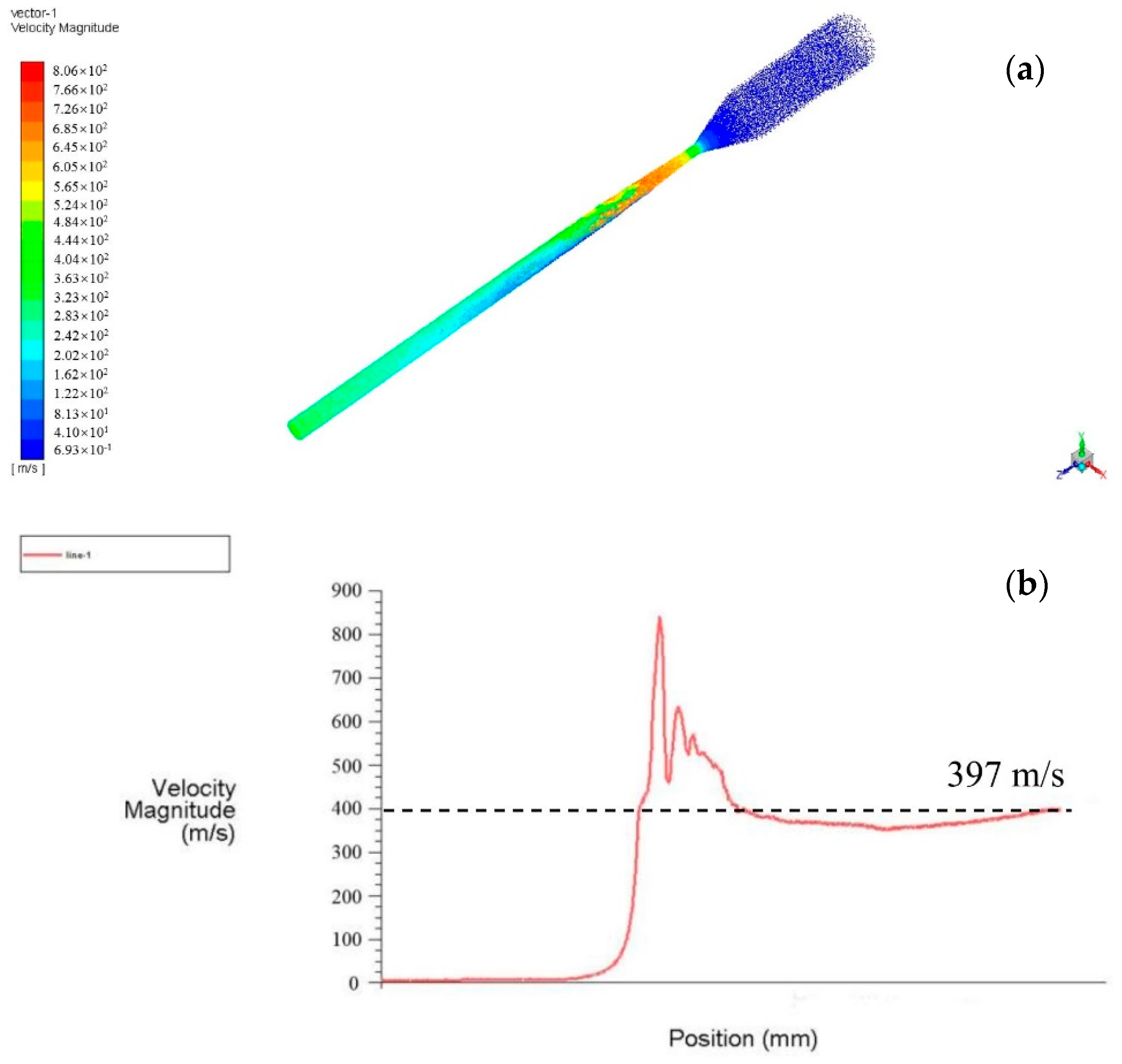
| Energy of powder | Thermal energy (Eth) Kinetic energy (Ek) | 0.46 × 10³ - | 300 - | 20 - | − 1 × 10⁻³ | − 397 | − 78 | 1.28 × 10⁵ − | |
| Fe | Cr | Ni | C | Co | Mo | Ca | O | |
|---|---|---|---|---|---|---|---|---|
| Point 1 | 59.3 | 13.9 | 13.2 | 5.7 | 2.2 | 2.1 | 2.1 | 1.5 |
| Point 2 | 57.7 | 11.5 | 16.7 | 7.1 | 3.1 | − | 1.9 | 2.0 |
| Point 3 | 60.1 | 15.4 | 7.5 | 3.2 | 6.2 | 5.1 | 0.7 | 1.8 |
| Point 4 | 63.2 | 14.7 | 6.8 | 2.1 | 6.5 | 4.3 | 0.1 | 2.3 |
Publisher’s Note: MDPI stays neutral with regard to jurisdictional claims in published maps and institutional affiliations. |
© 2021 by the authors. Licensee MDPI, Basel, Switzerland. This article is an open access article distributed under the terms and conditions of the Creative Commons Attribution (CC BY) license (https://creativecommons.org/licenses/by/4.0/).
Share and Cite
Wang, Q.; Qian, R.; Yang, J.; Niu, W.; Zhou, L.; Pan, X.; Su, C. Effect of High-Speed Powder Feeding on Microstructure and Tribological Properties of Fe-Based Coatings by Laser Cladding. Coatings 2021, 11, 1456. https://doi.org/10.3390/coatings11121456
Wang Q, Qian R, Yang J, Niu W, Zhou L, Pan X, Su C. Effect of High-Speed Powder Feeding on Microstructure and Tribological Properties of Fe-Based Coatings by Laser Cladding. Coatings. 2021; 11(12):1456. https://doi.org/10.3390/coatings11121456
Chicago/Turabian StyleWang, Qiang, Runling Qian, Ju Yang, Wenjuan Niu, Liucheng Zhou, Xinlei Pan, and Chengming Su. 2021. "Effect of High-Speed Powder Feeding on Microstructure and Tribological Properties of Fe-Based Coatings by Laser Cladding" Coatings 11, no. 12: 1456. https://doi.org/10.3390/coatings11121456
APA StyleWang, Q., Qian, R., Yang, J., Niu, W., Zhou, L., Pan, X., & Su, C. (2021). Effect of High-Speed Powder Feeding on Microstructure and Tribological Properties of Fe-Based Coatings by Laser Cladding. Coatings, 11(12), 1456. https://doi.org/10.3390/coatings11121456