Article

Characterization of YSZ Coatings Deposited on cp-Ti Using the PS-PVD Method for Medical Applications

1
Institute of Materials Engineering, University of Silesia in Katowice, 41-500 Chorzow, Poland
2
Department of Materials Science, Rzeszow University of Technology, 35-959 Rzeszów, Poland
3
Institute of Biomedical Engineering, University of Silesia in Katowice, 41-200 Sosnowiec, Poland
4
Faculty of Biochemistry, Biophysics and Biotechnology Jagielonian University, 30-387 Krakow, Poland
*
Author to whom correspondence should be addressed.
Coatings 2021, 11(11), 1348; https://doi.org/10.3390/coatings11111348
Submission received: 19 September 2021 / Revised: 24 October 2021 / Accepted: 26 October 2021 / Published: 2 November 2021
(This article belongs to the Special Issue Advances in Ceramic Protective Films and Coatings)

Abstract

:
A patient’s body accepting a bone implant depends not only on the biomaterial used, but also on its surface, which allows it to properly interact with bone cells. Therefore, research has focused on improving the bioactive and tribological properties of titanium and its alloys. Commercially pure titanium (cp-Ti) is widely used as a biomedical material. However, it is characterized by unsuitable tribological properties. In this work, yttria-stabilized zirconia (YSZ) was deposited on a cp-Ti substrate via plasma spray–physical vapor deposition (PS-PVD). The structural characteristics were determined using X-ray analysis (XRD). Additionally, the lattice parameters of each phase were determined using Rietveld’s method. High-resolution scanning microscopy (HR-SEM) showed a typical column structure of coatings that can be used with PS-PVD. Depending on the process parameters, the coatings differed in thickness in the range of 2.4–9.0 µm. The surface roughness also varied. The samples were subjected to nano-indenter testing. A slight change in hardness after deposition of the coating was observed, in addition to a significant decrease in the Young’s modulus. The Young’s modulus in relation to the metallic substrate was reduced to 58 or 78 GPa depending on the parameters of the spray-coating process.

1. Introduction

Nowadays, the most popular materials used for implants, such as dental and limb implants, hip joints, stents, or surgery tools, are metal alloys, such as stainless steel (316L), titanium alloys (Ti4Al6V), and cobalt–chromium alloys (CoCrMo) [1]. The implant materials should be characterized not only by high biocompatibility but also by mechanical properties similar to the properties of human bone (Young’s modulus ~30 GPa), in addition to excellent corrosion resistance [2]. Moreover, materials may contain toxic elements, such as V, Co, and Al, which can lead to many diseases [3]. Commercially pure titanium (cp-Ti, grade 2) seems to be a good candidate material for use in medical applications. Ti has high biocompatibility and corrosion resistance in human body fluids. Furthermore, pure Ti exhibits a lower elastic modulus (~105 GPa) than Ti4Al6V (~125 GPa) [4,5].
Despite these advantages, titanium has poor tribological properties, such as a high coefficient of friction, low harnesses, and poor abrasive wear resistance, compared with Ti alloys [6,7]. One of the methods to improve the tribological and osteocompatibility properties of Ti is modification of the implant surface by coatings. The modification not only improves tribological properties but also create a bioactive area. Creation of adequate roughness on the surface of a titanium implant and supporting it with bioactive elements is an effective way to improve osseointegration between bone and implant [8,9,10], leading to higher osteoblast adhesion and better integration of the tissue with the implant. In most cases, the bioactive coating materials used include hydroxyapatite (HAp) [11], Al2O3 [12], ZrO2 [13], or composites layers TiO2/TiN [14,15]. In particular, as shown by Kure-Chu et al., a thin TiO2/TiN nanolayer enhances wear resistance [16], while ZrO2 and Al2O3 are bioinert ceramics [17]. Moreover, zirconium dioxide has highly stable dimensional and chemical properties, suitable hardness, and relatively low wear. Therefore, it is an attractive material for medicine. ZrO2 occurs in three allotropic forms stable at different temperatures: cubic, monoclinic, and tetragonal [18]. To stabilize the tetragonal phase at room temperature, additives, such as yttrium oxide (Y2O3), cerium oxide (CeO2), or magnesium oxide (MgO), are used [19]. In recent years, zirconium oxide stabilized with yttrium has been applied as dental implants and fillings, hips (total hip replacement), and femoral heads [20,21]. Many in vitro investigations have shown that YSZ coating causes better osseointegration. In vivo tests have shown that metal oxides are not cytotoxic, mutagenic, or carcinogenic [22]. Moreover, zirconium dioxide can be antibacterial against E. coli [18,23,24].
Nowadays, scientists use different methods to produce coatings, depending on changing chemical or physical parameters [25]. For example, micro-arc oxidation (MAO) is used for nonferrous materials. In this method, coatings are obtained through a chemical reaction initiated by an electric potential (higher than standard anodic oxidation) [26]. Other methods are the sol–gel method based on colloidal solutions [27], electrophoretic deposition involving colloidal solution, ceramic powder included in solution deposited on a substrate by an electric current [28], or physical techniques, such as physical vapor deposition (PVD) and atmospheric plasma spray (APS) [29]. One of the new promising methods of ceramic layer formation is plasma spray–physical vapor deposition (PS-PVD) [10]. PS-PVD technology, based on the conventional low-pressure plasma spray (LPPS) method, enables controlling the thickness and structure of ceramic coatings deposited on different materials [30]. One classic PVD technique is air plasma spray, where a powder is subjected to a high-temperature plasma flame, it is accelerated by plasma clouds, and then the melted powder is sprayed on a relatively cold substrate using a plasma jet, where crystallization occurs [31].
The currently promising and alternative methods to APS are plasma spray–physical vapor deposition (PS-PVD) and very-low-pressure plasma spraying (LPPS) [32]. These methods involve spraying and depositing melted or partly melted particles of powder on a metal substrate. The produced coatings have characteristically different microstructures. They are dense or columnar, depending on the process parameters used. Plasma spray–physical vapor deposition allows a wider spraying area compared with APS [33,34]. From a medical point of view, it is important for coatings to be characterized by the same phase composition, thickness, and surface roughness throughout the entire spray area. Therefore, in this paper, the PS-PVD technique was applied for Ti surface modification.
The main focus of this work, the YSZ coating, was deposited on a titanium substrate (cp-Ti, grade 2) using the PS-PVD method. The deposited coatings were extensively researched in terms of morphology, structure, corrosion resistance, and cell viability tests. The research material under study is expected to have potential medical applications, such as implants.

2. Materials and Methods

Plasma spray–physical vapor deposition (PS-PVD)—Commercially pure titanium rods (Ø 9 mm) were used as a substrate. The chemical composition of cp-Ti is shown in Table 1. The substrate was cleaned and de-greased by isopropanol alcohol and distilled water before deposition. For the coating, commercially available yttria-stabilized zirconia powder (7.5Y2O3-ZrO2, Metco 6700, Oerlikon, Pfäffikon, Switzerland) was used. Plasma spray–physical vapor deposition (PS-PVD) was used for the production of coatings. The experiment was performed using a 03CP-type plasma gun and a 60CD powder feeder. Constant process parameters were applied, such as plasma gases (He = 60/Ar = 35 normal liters per minute (NLPM)), power current 2400 A, sample rotation 20 rpm, and chamber pressure 150 Pa, based on previous research [35]. Two different deposition times of 50 and 200 s were used for each sample (Table 2).
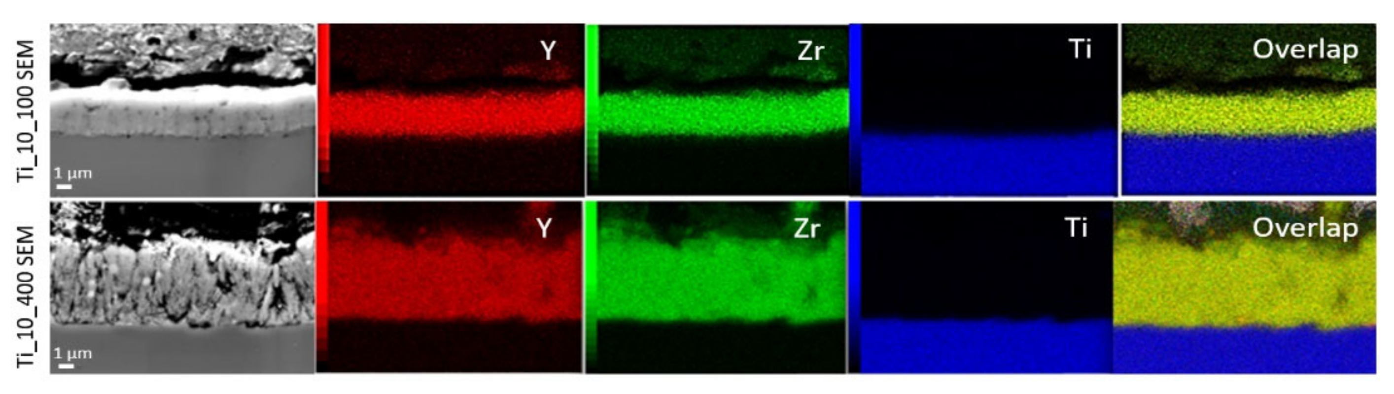
Next, rods with YSZ coatings were cut into slices of 5 mm thickness The deposition process obtained two representative samples, Ti_10_100 and Ti_10_400, which were subjected to extensive material testing.
Characterization of ceramic coatings—Quantitative and qualitative X-ray analysis was carried out using a Philips X’Pert PW 3040/60 diffractometer (PANalytical, Almelo, The Netherlands), with used CuKα radiation (λ = 1.54178 Ǻ), voltage 40 kV, and current 30 mA. The measurement was carried out at a range of angles from 10° 2θ to 140° 2θ, with step scanning at 0.04 steps. The ICCD Card PDF 4 database was used to analyze the resulting diffractograms. Structural analyses of the obtained coatings were performed using Rietveld’s method.
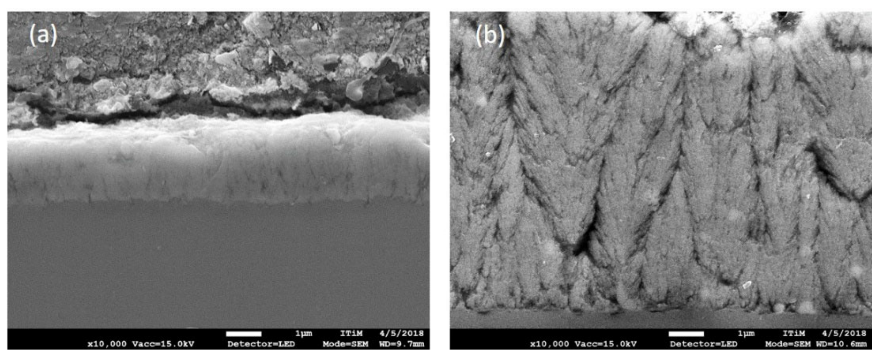
To observe the cross sections, columnar structures, and surfaces of the obtained coatings, a JEOL JMS-7100F TTL LV high-resolution scanning microscope (JEOL, Tokyo, Japan) with an accelerating voltage of 15 kV was used. The cross-sectional and top views of samples were characterized. An EDS detector was used to determine the maps of element distribution. HR-SEM EDS analysis was carried out to observe the cross sections of the obtained coatings. To determine the linear dispersion of energy and the map of energy dispersion, a JEOL 6480 JSM 6480 scanning microscope (JEOL, Tokyo, Japan) with an accelerating voltage of 20 kV was used, with standard EDS equipment for linear chemical analysis of the cross sections of the samples.
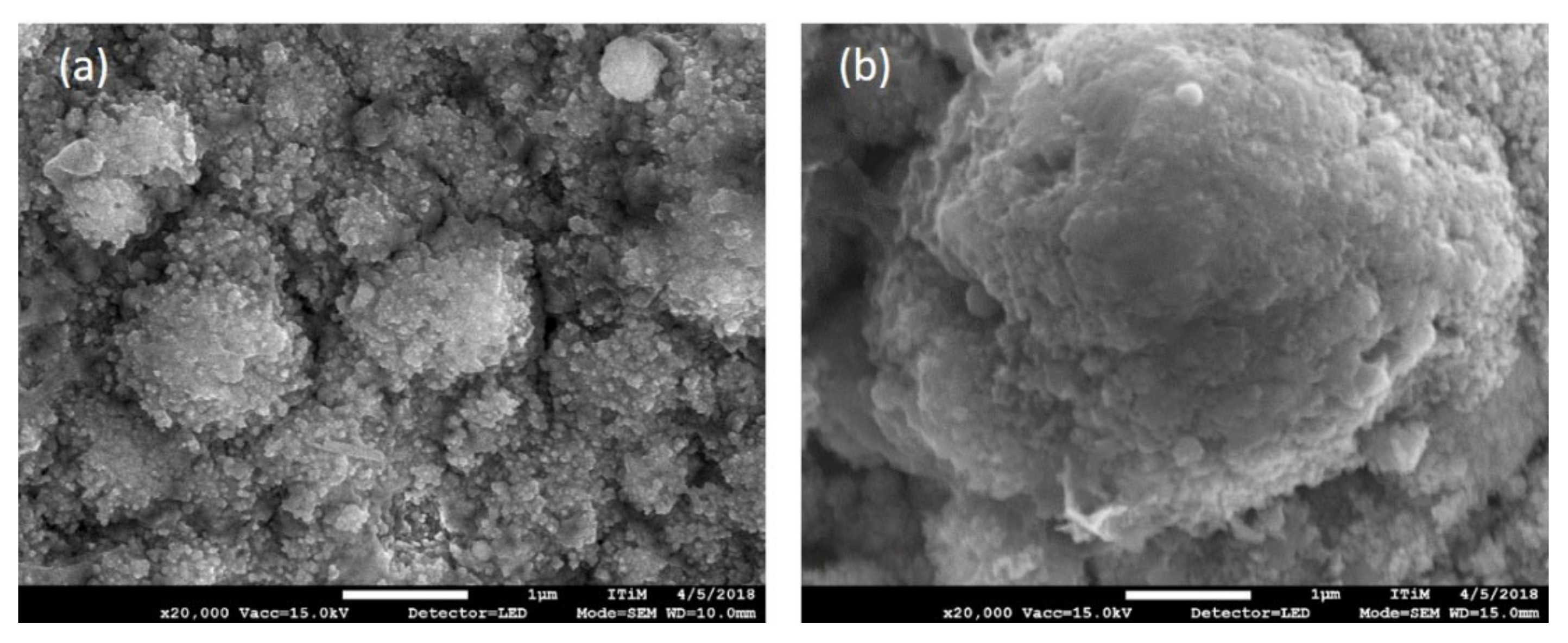
A JEOL JSM 6480 (JEOL, Tokyo, Japan) scanning electron microscope (SEM) with an accelerating voltage of 20 kV was used to observe images of surfaces and the morphology of obtained coatings after corrosion resistance measurements. EDS analysis was completed of the top view of the obtained coatings in 15 different areas.
Electrochemical measurements were carried out using a Metrohm/Eco Chemie Autloab PGSTAT30 Potentiostat/Galvanostat Electrochemical System (Metrohm Middle East FZC, Sharjah, UAE). A three-electrode electrochemical cell was used where the material under study was the working electrode (WE), the Pt mesh was used as a counter electrode (CE), and the saturated calomel electrode (SCE) with a Luggin capillary was the reference electrode (RE). The in vitro corrosion resistance of the tested materials was investigated in Ringer’s solution (Table 3) deaerated with argon (Ar, 99.999%) at 37 °C. The open circuit potential (EOC) and potentiodynamics polarization methods were applied. The EOC was registered until a stable potential value was found. Anodic polarization curves were registered potentiodynamically at a sweep rate of v = 4 mV s−1 in the potential range from EOC −150 mV to 9 V vs. SCE.
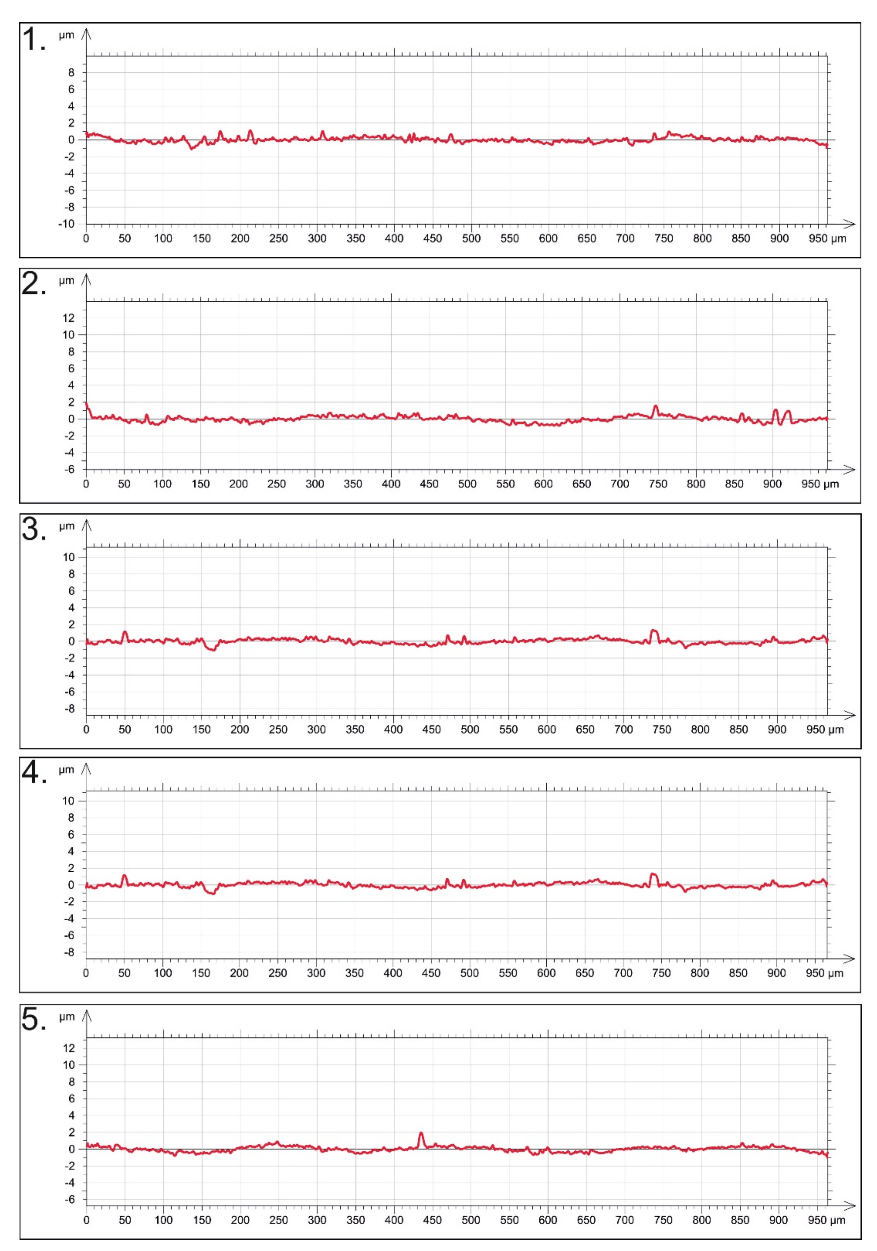
The roughness profile of the obtained coatings was determined by a Mitutoyo SURFTEST SJ-500 profilometer (Mitutoyo, Tokyo, Japan) to determinate changes in roughness. The following parameters of the raw profile were analyzed: arithmetic mean deviation (RA), maximum peak height (RP), maximum height (RZ), and maximum valley depth (RV). Five measurements were made for each sample, with a working distance of 2 cm for each sample.
Topography measurements and roughness cross-sections of the obtained coatings were characterized with a Hysitron TI 950 nano-indenter (Hysitron, Eden Prairie, MN, USA) on 40 µm × 40 µm areas. The experiments were carried out with a Bregovic tip at a load of 500 µN.
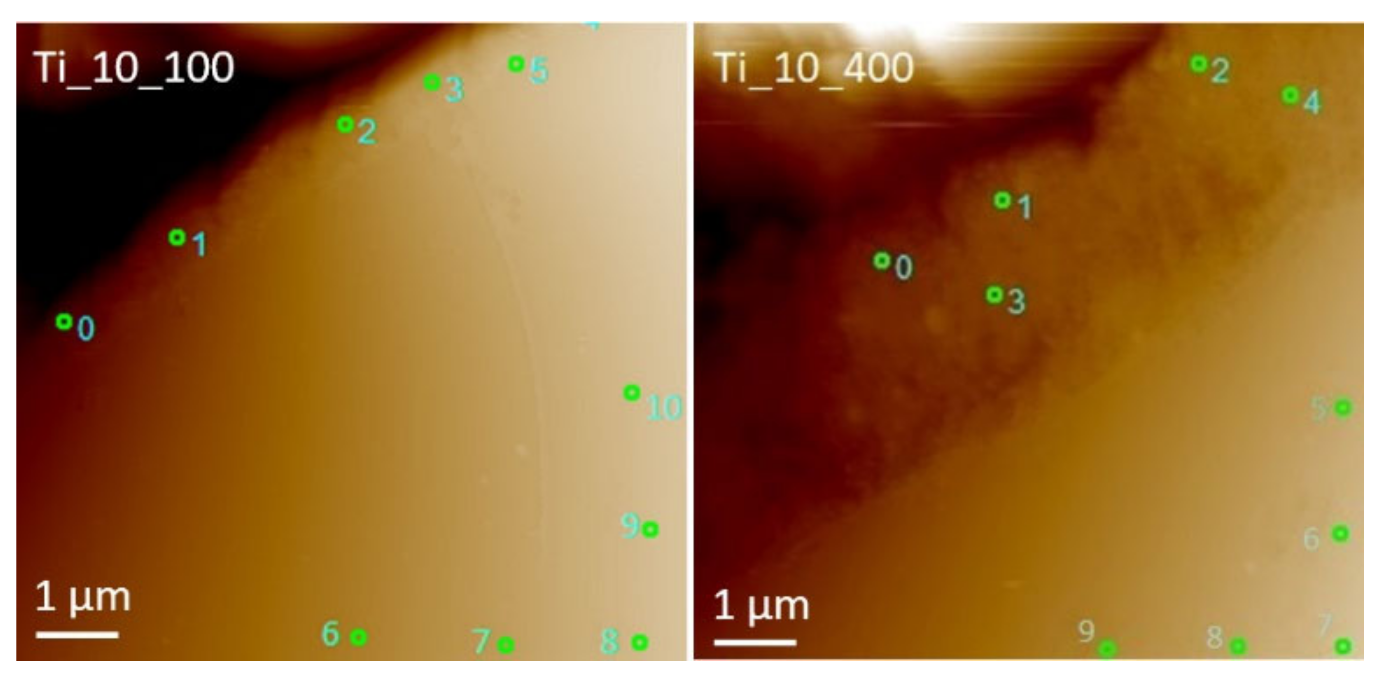
Surface observations of the obtained coatings were made by an Olympus LEXT OLS-4000 confocal scanning microscope (Olympus Corp., Tokyo, Japan) with a wavelength of 405 nm. Observations were made at a magnification of ×20. Three-dimensional pictures were prepared using the free software Gwyddion 2.51.
A viability assay was carried out using human fibroblasts. Fibroblasts were seeded on investigated surfaces at a density of 50 × 103/cm2 for 24 h before viability examination and cultured under strictly controlled conditions: 5% CO2 and temperature 37 °C. For staining, the cell cultures were incubated for 10 min (RT) with the fluorescent dyes fluorescein diacetate (FDA) and ethidium bromide (EB) at concentrations provided by the producers. After washing with phosphate-buffered saline (PBS), the samples were mounted in glass chambers and then visualized with a Leica DMI6000B fluorescence microscope equipped with a DFC360FX CCD camera (Leica, Wetzlar, Germany).

3. Results and Discussion

3.1. Surfaces and Cross-Section Properties of Coatings

HR-SEM showed a characteristic columnar structure (Figure 1a,b). The microstructures of the obtained columns were different. In Ti_10_400, the coatings had many gaps between single columns, but no microcracks, crumbing, and delamination. Thus, each embedded coating was tight, homogeneous, and consistent. However, the thinner coating (Ti_10_100) was more compact with a smaller number of pores. As shown by Zhang et al. [32], higher porosity is associated with the occurrence of a quasi-columnar coating structure. The spaces between columns are typical for the method used. According to Gao et al. [36], during powder injection into a plasma stream, powder particles easily melt and, at the same time, are accelerated by plasma clouds. The powder turns into drops striking the substrate. Due to the high acceleration, the drops spatter to form nuclear centers. Most likely, the drops of sprayed material do not hit the same place on the substrate, creating spaces. These spaces can also be internal pores. As the spraying time increases, the number of spaces increases with an increase in the columns. This theory is consistent with the process parameters used in the present work. Clearly, there are changes in the number of repetitive spaces between the columns with an increase in the SWAP parameter (representing the cycle of the burner movement over the sample during the PS-PVD process over the sample, which enables the conversion to the deposition time). In addition, the SWAP parameter significantly affects the thickness of the obtained coating.
During PS-PVD, coating formation depends on not only the pressure, the time of spraying, and the speed of the powder feed, but also on the temperature of the substrate itself and the distance from the plasma gun. The spraying process of YSZ columns with different thicknesses and microstructures with different PS-PVD process parameters is presented in [37]. The authors also showed the randomness of crystal orientation in the columns. Figure 1 shows more unmelted particles in Ti_10_400 in the inside columns than Ti_10_100 coatings. Figure 2 shows top-view images of the coatings on Ti_10_100 and Ti_10_400. HR-SEM showed that both deposited coatings had different surface roughness. This feature has a beneficial effect on bone tissue adhesion because the contact surface between bone tissue and implant increases [38].
Moreover, the surface of the samples showed many pores and unmelted particles, which further differentiated the surface. As Tang et al. [39] showed, the formation of an already porous coating significantly improves the binding of bone tissue. Ti_10_100 appeared to have fewer unmelted molecules on the surface than Ti_10_400, which minimizes the risk of detaching unmerged particles during potential medical applications. The finding is consistent with the above cross-section coating tests. The surface of the samples showed many pores and unmelted particles, and they also look like “cauliflower” structures.
Images were taken at a magnification of ×20,000 (Figure 3). Significant differences in the size of individual columns were observed. Clearly, larger single “cauliflowers” were seen in Ti_10_400. In Ti_10_100, individual spaces between separate columns were observed only at higher magnification. In addition, we noted the presence of the so-called surface splats on the surface of Ti_10_100. In both samples, we observed the conical structure of the columns.
Surface irregularities can be explained in two ways. The first possibility is that unmelted particles inside the column structure are the effect of irregularities [36]. The second possibility is shading. The substrate has a certain roughness, and accelerated particles settle at a certain angle and have no possibility of movement; therefore, the unevenness of the substrate cannot be smoothed out [40]. A similar surface from YSZ using PS-PVD is presented in [41,42,43]. Differentiation of the surface was also visible on images obtained by a confocal microscope (Figure 4). In Ti_10_400, the domed tips of individual columns were clearly observable, which, as previously mentioned, is related to the occurrence of a quasi-columnar coating structure. Moreover, the domed columns tips were evenly distributed on the surface of the substrate, although the surface was rounded (cp-Ti has the shape of a cylinder). However, Ti_10_100 clearly showed fewer dome tips, which significantly affected the surface roughness.
Analysis by an EDS detector was used to investigate the chemical composition at the top of the deposited coatings. The chemical analysis reported the presence of Zr, Y, Ti, and O. The investigation did not display undesirable elements.
X-ray analysis (Figure 5) revealed the presence of phases of coatings: Zr0.935Y0.065O1.968, TiO, and α-Ti phases. The highest peak for Zr0.935Y0.065O1.968 was detected for the thickest sample, Ti_10_400. For a thicker coating (Ti_10_400), the TiO phase was absent, presumably because the XRD beam did not reach the interface and could not be detected. We observed a decrease in the TiO phase with an increase in sample thickness. Most likely, the discussed phase comes from the oxidized substrate. Importantly, despite the high temperature of PS-PVD, yttrium-stabilized zirconium oxide powder does not change into another phase, which means that the initial powder used in the coating process does not affect the phase composition. Table 4 shows the lattice parameters for each phase calculated using Rietveld’s method.
Generally, all parameters of Zr0.935Y0.065O1.968 (YSZ) and α-Ti phases changed slightly depending on the process parameters used. In the Zr0.935Y0.065O1.968 phase, the lattice parameter a0 increased, while c0 decreased compared with ICCD data. However, the parameters for both coatings did not differ significantly from each other. In the case of the α-Ti phase, a significant increase in lattice parameters was observed compared with ICCD data. However, both coatings showed similar values. Most likely, PS-PVD has a modest effect on the deformation of the elementary cell. Using HR-SEM with an EDS detector, the cross-sections of both samples were observed, and distribution maps of elements made (Figure 6). In both samples, chemical analysis showed the presence of elements such as Ti, which is included in the substrate, and Zr and Y, corresponding to the coatings. The maps indicated that between Ti and Zr is a diffusion area, which is most beneficial from a medical point of view, because the coating is more strongly associated with the substrate, which reduces the risk of coating delamination or damage.
Linear chemical analysis of the cross-sections of the samples (Figure 7) clearly showed changes in the content of individual elements in the samples. The lines of individual elements intersected at the coating–substrate boundary, suggesting that diffusion of the coating material into the substrate occurred.

3.2. Mechanical Properties of Deposited Coatings

Measurements of the coating surface roughness showed that the RA of individual coatings significantly differed, as clearly illustrated by the graphs obtained from the profilometer for each deposited coating (Figure 8 and Figure 9). The average value of roughness was 0.25 and 0.90 for Ti_10_100 and Ti_10_400, respectively. The graphs show a slight wave. However, this may be related to single columns that are visible on microscopic images. The other parameters also showed lower values for the thinner coating (Ti_10_100). The roughness parameters are summarized in Table 5. A slight increase in surface roughness allows better osseointegration. As reported by Dohan Ehrenfest et al. [44], increased roughness allows the surface energy to increase, which affects the absorption of proteins, as well as bone cell migration and proliferation, and, consequently, osseointegration improvement. As is known, the literature on the subject distinguishes micro- and nano-scales of surface roughness. Each of them is associated with a different ability for osseointegration. The obtained roughness values equal to 0.25 and 0.90 µm, respectively, for Ti_10_100 and Ti_10_400 are classified as nano-roughness [45]. Changing the PS-PVD parameters allows for better control of the roughness of the obtained coatings. Table 4 lists the average thickness of the coatings. The average thickness of the coatings was 2.4 and 9.0 µm for Ti_10_100 and Ti_10_400, respectively, which confirms previous assumptions about their different thicknesses.
The hardness and Young’s modulus measured by nano-indentation for both the coating and the metallic substrate are summarized in Table 6. The exact measurement points are shown in Figure 10, and the image was obtained by an atomic force microscope (AFM).
In Ti_10_100, there was no significant change in the hardness for both the substrate and the coating; the hardness for both was 5 GPa. In contrast, Ti_10_400 showed a decrease in hardness from 13 to 5 GPa. In the case of the Ti_10_400 coating, the visible decrease in hardness may be related to the column structure of the coating itself, which obtains less-dense coatings. Hence, there is a high probability of hitting the indent during the measurement into the pores instead of the YSZ material. Young’s modulus significantly decreased to 78 and 58 GPa for Ti_10_100 and Ti_10_400, respectively. Shao et al. [46] reported that hardness and Young’s modulus of coatings vary depending on the PS-PVD parameters used, such as distance and spraying time. However, Shao et al. [47] also showed changes in the discussed parameters, depending on the tested coating location (top, bottom, or middle). In summary, the changes introduced in the PS-PVD process significantly affect coating properties, so future studies should focus on this aspect. From the medical application point of view, the Young’s modulus of the studied materials decreases. Generally, to preve9nt bone stiffening and the bone-shielding effect and to avoid damage to implants, it is necessary to design implants whose stiffness module, among other things, is as close to the human bone module as possible [5,48].

3.3. Corrosion Test

In the in vitro studies, the EOC measurements were carried out until the ionic-electron equilibrium related to the formation of the double electrical layer at the electrolyte–sample surface interface was stabilized. The registered values of the EOC for tested materials are summarized in Table 7. Based on the registered polarization curves, log j = f (E), the Tafel extrapolation method was applied to determine the corrosion resistance parameters. The results of the Tafel extrapolation are summarized in Table 6. The value of Ecor shifted towards noble potentials, indicating slightly better corrosion resistance for sample Ti_10_400. The determined values of corrosion current density and corrosion rate (CR) are characteristic for materials with very high corrosion resistance (Table 7). Moreover, the CR of 0.001 mm/yr and lower indicates the high resistance to pitting corrosion of the investigated material in Ringer’s solution at 37 °C.
The potentiodynamic curves registered for the studied electrodes in Ringer’s solution at 37 °C are typical for self-passivating materials (Figure 11). One can observe the lack of a rapid increase in the value of current densities on an anodic branch registered for the sample Ti_10_100 in the potential window up to 9 V vs. SEC. The break-down potential (Ebd) cannot be distinguished, which suggests no coating damage during the test. The slight increase in current density around 3 V vs. SCE might be connected with oxidation of the nonstoichiometric oxides during increasing potential values.
On the potentiodynamic curve registered for the sample Ti_10_400, there is a passive range of 1–1.5 V vs. SCE. In addition, a sharp increase in the current density around 1.5 V vs. SCE, which may indicate surface dissolution, can be observed. For more anodic potential values, the creation and dissolution of the layer occur simultaneously. In the range of potentials from 2.4 to 6 V vs. SCE, a broad plateau related to the transpassivation process can be observed. The break-down potential, which indicates initiation of pitting corrosion, of the oxide layer on the tested electrode surface is observed around 6 V vs. SCE. Above this value, the anodic dissolution of the transpassive layer occurs. It should be added that the break-down potential observed for titanium and its common implant alloys in a biological milieu stands at around 0.5–4.5 V [49,50]. By comparing obtained results with the literature data, it can be concluded that the studied materials could have a potential application in medicine.
Destruction of the coating is illustrated in the image in Figure 12. The coating of Ti_10_400 was delaminated by penetration of Ringer’s solution. The coating crumbled with sharp edges. However, in places where the coating did not fall off, microcracks were observed along column domes. In addition, the corrosive electrolyte penetrated deeply under the coating, causing it to swell. The thinner coating (Ti_10_100), at lower magnifications, did not show any influence of an aggressive environment on its microstructure. Only many inequalities, empty porous places, and splats were observed. However, at a magnification over ×1000, we saw single pores resembling the shape of an oval in the image, which showed the pitting corrosion effect [51]. The size of pitting was about 10 µm. The pits were uneven and torn on the sides, which indicated gradual destruction of the coating by the aggressive Ringer’s solution. Furthermore, there was no delamination of the coating around the pitting. Microscopic examination also did not show inter-column microcracks as in the case of Ti_10_400. These corrosion test results clearly suggest that a thinner coating (Ti_10_100) seems better for biomedical applications.

3.4. Viability Test

Figure 13 shows the bone cell culture scattered on zirconium-oxide-deposited surfaces, with cp-Ti as a control sample. The green color of the fibroblasts indicates living cells, while the red color indicates dead cells [52]. Due to the cylindrical shape of the samples, the microscopic image was sharp only in a certain fragment. Nevertheless, good fibroblast viability (about 98%) was observed in Ti_10_100 compared with the control sample. The shape of the cells was satisfactory, although it should be more flattened. Single dead cells were observed in some places on the test surface. Fibroblasts have the ability to adhere evenly over the entire coating surface. Interestingly, similar results of fibroblast proliferation on the ZrO2 surface were obtained in [53]. The opposite behavior was observed in Ti_10_400, where proliferation was lower compared with Ti_10_100. Moreover, Ti_10_400 showed an unacceptable level of fibroblast viability and a significant number of dead cells. Cells appeared to be larger compared to Ti_10_100; however, they were neither flattened nor cylindrical. No cell agglomeration was observed on the examined surfaces. However, the Ti_10_100 coating showed better cell viability, much lower cytotoxicity, and a better shape of individual cells. In conclusion, the Ti_10_400 coating is not suitable for use as an implant surface due to the high risk of inflammation and/or implant rejection.

4. Conclusions

The conducted research results indicate that PS-PVD allows one to obtain compact, homogeneous, characteristic, columnar yttrium-stabilized zirconium oxide coatings on a metallic cp-Ti substrate suitable for medical applications. Using variable parameters of the PS-PVD process significantly affects the structure and properties of the deposited coatings. The above experiment shows that by only changing the deposition time, different surface properties were obtained, such as surface development (topography, roughness) and thickness. At the same time, it was shown that spraying the coating does not cause significant structural changes and does not introduce contaminants into the material. The above research allow us to state that the deposited coatings do not show microcracks and delamination and do not crumble. However, unmelted particles were present during PS-PVD inside and on the surface, and the amount of unmelted particles depends on the process parameters used. In addition, it was proven that the deposited coatings slightly changed the hardness value of the material, although they significantly reduced the Young’s modulus. It has been found that Ti_10_100 is a good material for use in an environment of aggressive body fluids. In contrast, Ti_10_400 has poor bone cell viability and less adhesion. The cells are mostly round. The Ti_10_100 samples has good adhesion and distribution, and the cell viability is comparable to the control sample. Importantly, it was indicated that the Ti_10_100 coating could be used as potential bone implants. Further work should focus on the development of optimal thickness and roughness and the continuous reduction of Young’s modulus to improve osseointegration and bioactivity and reduce the risk of bone stiffness.

Author Contributions

Conceptualization, G.D. and J.B.; methodology, G.D., J.B., T.K., M.G. and D.R.; formal analysis, G.D., J.B., I.M., T.K., M.G., J.M., D.B., S.S., M.S., D.R. and M.P.; investigation, G.D., J.B., T.K., M.G. and D.R.; writing—original draft preparation, G.D. and J.B.; writing—review and editing, G.D. and J.B.; supervision, G.D. All authors have read and agreed to the published version of the manuscript.

Funding

This research received no external funding.

Institutional Review Board Statement

Not applicable.

Informed Consent Statement

Not applicable.

Data Availability Statement

The data are available from the author upon request.

Conflicts of Interest

The authors declare no conflict of interest.

References

  1. Kazek-Kȩsik, A.; Krok-Borkowicz, M.; Pamuła, E.; Simka, W. Electrochemical and biological characterization of coatings formed on Ti-15Mo alloy by plasma electrolytic oxidation. Mater. Sci. Eng. C 2014, 43, 172–181. [Google Scholar] [CrossRef] [PubMed]
  2. Campanelli, L.C.; Duarte, L.T.; da Silva, P.S.C.P.; Bolfarini, C. Fatigue behavior of modified surface of Ti-6Al-7Nb and CP-Ti by micro-arc oxidation. Mater. Des. 2014, 64, 393–399. [Google Scholar] [CrossRef]
  3. Niinomi, M. Mechanical properties of biomedical titanium alloys. Mater. Sci. Eng. A 1998, 243, 231–236. [Google Scholar] [CrossRef]
  4. Santos, P.F.; Niinomi, M.; Cho, K.; Nakai, M.; Liu, H.; Ohtsu, N.; Hirano, M.; Ikeda, M.; Narushima, T. Microstructures, mechanical properties and cytotoxicity of low cost beta Ti-Mn alloys for biomedical applications. Acta Biomater. 2015, 26, 366–376. [Google Scholar] [CrossRef] [PubMed]
  5. Long, M.; Rack, H.J. Titanium alloys in total joint replacement—A materials science perspective. Biomaterials 1998, 19, 1621–1639. [Google Scholar] [CrossRef]
  6. Torrent, F.; Lavisse, L.; Berger, P.; Pillon, G.; Lopes, C.; Vaz, F.; Marco de Lucas, M.C. Influence of the composition of titanium oxynitride layers on the fretting behavior of functionalized titanium substrates: PVD films versus surface laser treatments. Surf. Coat. Technol. 2014, 255, 146–152. [Google Scholar] [CrossRef]
  7. Lisiecki, A.; Piwnik, J. Tribological characteristic of titanium alloy surface layers produced by diode laser gas nitriding. Arch. Metall. Mater. 2016, 61, 543–552. [Google Scholar] [CrossRef]
  8. Cheng, M.; Qiao, Y.; Wang, Q.; Jin, G.; Qin, H.; Zhao, Y.; Peng, X.; Zhang, X.; Liu, X. Calcium Plasma Implanted Titanium Surface with Hierarchical Microstructure for Improving the Bone Formation. ACS Appl. Mater. Interfaces 2015, 7, 13053–13061. [Google Scholar] [CrossRef]
  9. Soboyejo, W.O.; Mercer, C.; Allameh, S.; Nemetski, B.; Marcantonio, N.; Ricci, J.L. Multi-scale microstructural characterization of micro-textured Ti-6Al-4V surfaces. Key Eng. Mater. 2001, 199, 203–230. [Google Scholar] [CrossRef]
  10. Xie, Y.; Zheng, X.; Huang, L.; Ding, C. Influence of hierarchical hybrid micro/nano-structured surface on biological performance of titanium coating. J. Mater. Sci. 2012, 47, 1411–1417. [Google Scholar] [CrossRef]
  11. Choy, M.T.; Yeung, K.W.; Chen, L.; Tang, C.Y.; Tsui, G.C.P.; Law, W.C. In situ synthesis of osteoconductive biphasic ceramic coatings on Ti6Al4V substrate by laser-microwave hybridization. Surf. Coat. Technol. 2017, 330, 92–101. [Google Scholar] [CrossRef]
  12. Hamdi, D.A. Investigation the properties of hip implantation structure based on nanotechnology by using radio frequency magnetron sputtering. Int. J. Energy Environ. 2017, 6, 515–522. [Google Scholar]
  13. Cai, Y.; Quan, X.; Li, G.; Gao, N. Anticorrosion and Scale Behaviors of Nanostructured ZrO2 -TiO2 Coatings in Simulated Geothermal Water. Ind. Eng. Chem. Res. 2016, 55, 11480–11494. [Google Scholar] [CrossRef]
  14. Nikolova, M.P.; Valkov, S.; Parshorov, S.; Yankov, E.; Petrov, P. Biomineralization of titanium alloy with surface micro- and nanoscaled modifications. Key Eng. Mater. 2019, 813, 165–170. [Google Scholar] [CrossRef]
  15. Zhang, P.; Wang, X.; Lin, Z.; Lin, H.; Zhang, Z.; Li, W.; Yang, X.; Cui, J. Ti-Based Biomedical Material Modified with TiOx/TiNx Duplex Bioactivity Film via Micro-Arc Oxidation and Nitrogen Ion Implantation. Nanomaterials 2017, 7, 343. [Google Scholar] [CrossRef] [Green Version]
  16. Ye, Y.; Kure-Chu, S.Z.; Sun, Z.; Matsubara, T.; Tang, G.; Hihara, T.; Okido, M.; Yashiro, H. Self-lubricated nanoporous TiO2-TiN films fabricated on nanocrystalline layer of titanium with enhanced tribological properties. Surf. Coat. Technol. 2018, 351, 162–170. [Google Scholar] [CrossRef]
  17. Richard, C.; Kowandy, C.; Landoulsi, J.; Geetha, M.; Ramasawmy, H. Corrosion and wear behavior of thermally sprayed nano ceramic coatings on commercially pure Titanium and Ti-13Nb-13Zr substrates. Int. J. Refract. Met. Hard Mater. 2010, 28, 115–123. [Google Scholar] [CrossRef]
  18. Piconi, C.; Burger, W.; Richter, H.G.; Cittadini, A.; Maccauro, G.; Covacci, V.; Bruzzese, N.; Ricci, G.A.; Marmo, E. Y-TZP ceramics for artificial joint replacements. Biomaterials 1998, 19, 1489–1494. [Google Scholar] [CrossRef]
  19. Piconi, C.; Maccauro, G. Zirconia as a ceramic biomaterial. Biomaterials 1999, 20, 1–25. [Google Scholar] [CrossRef]
  20. Yin, L.; Nakanishi, Y.; Alao, A.R.; Song, X.F.; Abduo, J.; Zhang, Y. A Review of Engineered Zirconia Surfaces in Biomedical Applications. Procedia CIRP 2017, 65, 284–290. [Google Scholar] [CrossRef]
  21. Depprich, R.; Ommerborn, M.; Zipprich, H.; Naujoks, C.; Handschel, J.; Wiesmann, H.P.; Kübler, N.R.; Meyer, U. Behavior of osteoblastic cells cultured on titanium and structured zirconia surfaces. Head Face Med. 2008, 4, 29. [Google Scholar] [CrossRef] [Green Version]
  22. Kunčická, L.; Kocich, R.; Lowe, T.C. Advances in metals and alloys for joint replacement. Prog. Mater. Sci. 2017, 88, 232–280. [Google Scholar] [CrossRef]
  23. Kaliaraj, G.S.; Bavanilathamuthiah, M.; Kirubaharan, K.; Ramachandran, D.; Dharini, T.; Viswanathan, K.; Vishwakarma, V. Bio-inspired YSZ coated titanium by EB-PVD for biomedical applications. Surf. Coat. Technol. 2016, 307, 227–235. [Google Scholar] [CrossRef]
  24. Depprich, R.; Zipprich, H.; Ommerborn, M.; Mahn, E.; Lammers, L.; Handschel, J.; Naujoks, C.; Wiesmann, H.P.; Kübler, N.R.; Meyer, U. Osseointegration of zirconia implants: An SEM observation of the bone-implant interface. Head Face Med. 2008, 4, 25. [Google Scholar] [CrossRef] [PubMed] [Green Version]
  25. Niu, R.; Li, J.; Wang, Y.; Chen, J.; Xue, Q. Structure and tribological behavior of GLCH/nitride coupled coatings on Ti6Al4V by nitriding and magnetron sputtering. Diam. Relat. Mater. 2016, 64, 70–79. [Google Scholar] [CrossRef]
  26. Zhong, Y.; Shi, L.; Li, M.; He, F.; He, X. Characterization and thermal shock behavior of composite ceramic coating doped with ZrO2particles on TC4 by micro-arc oxidation. Appl. Surf. Sci. 2014, 311, 158–163. [Google Scholar] [CrossRef]
  27. Lorenzetti, M.; Pellicer, E.; Sort, J.; Baró, M.D.; Kovač, J.; Novak, S.; Kobe, S. Improvement to the corrosion resistance of Ti-based implants using hydrothermally synthesized nanostructured anatase coatings. Materials 2014, 7, 180–194. [Google Scholar] [CrossRef] [Green Version]
  28. Mohan, L.; Durgalakshmi, D.; Geetha, M.; Sankara Narayanan, T.S.N.; Asokamani, R. Electrophoretic deposition of nanocomposite (HAp + TiO2) on titanium alloy for biomedical applications. Ceram. Int. 2012, 38, 3435–3443. [Google Scholar] [CrossRef]
  29. Khor, K.A.; Cheang, P. Plasma sprayed hydroxyapatite(HA) coatings produced with flame spheroidised powders. J. Mater. Process. Technol. 1997, 63, 271–276. [Google Scholar] [CrossRef]
  30. Mauer, G.; Vaßen, R. Coatings with Columnar Microstructures for Thermal Barrier Applications. Adv. Eng. Mater. 2020, 22, 1900988. [Google Scholar] [CrossRef]
  31. Xiong, H.B.; Zheng, L.L.; Li, L.; Vaidya, A. Melting and oxidation behavior of in-flight particles in plasma spray process. Int. J. Heat Mass Transf. 2005, 48, 5121–5133. [Google Scholar] [CrossRef]
  32. Zhang, B.; Wei, L.; Guo, H.; Xu, H. Microstructures and deposition mechanisms of quasi-columnar structured yttria-stabilized zirconia coatings by plasma spray physical vapor deposition. Ceram. Int. 2017, 43, 12920–12929. [Google Scholar] [CrossRef]
  33. Góral, M.; Kubaszek, T.; Kotowski, S.; Sieniawski, J.; Dudek, S. Influence of deposition parameters on structure of TBCS deposited by PS-PVD method. Int. Sci. Conf. Corros. 2015, 227, 369–372. [Google Scholar] [CrossRef]
  34. Goral, M.; Kotowski, S.; Nowotnik, A.; Pytel, M.; Drajewicz, M.; Sieniawski, J. PS-PVD deposition of thermal barrier coatings. Surf. Coat. Technol. 2013, 237, 51–55. [Google Scholar] [CrossRef]
  35. Góral, M.; Swadźba, R.; Kubaszek, T. TEM investigations of TGO formation during cyclic oxidation in two- and three-layered Thermal Barrier Coatings produced using LPPS, CVD and PS-PVD methods. Surf. Coat. Technol. 2020, 394, 125875. [Google Scholar] [CrossRef]
  36. Gao, L.; Wei, L.; Guo, H.; Gong, S.; Xu, H. Deposition mechanisms of yttria-stabilized zirconia coatings during plasma spray physical vapor deposition. Ceram. Int. 2016, 42, 5530–5536. [Google Scholar] [CrossRef]
  37. Zhang, B.; Wei, L.; Gao, L.; Guo, H.; Xu, H. Microstructural characterization of PS-PVD ceramic thermal barrier coatings with quasi-columnar structures. Surf. Coat. Technol. 2017, 311, 199–205. [Google Scholar] [CrossRef]
  38. Agarwal, R.; García, A.J. Biomaterial strategies for engineering implants for enhanced osseointegration and bone repair. Adv. Drug Deliv. Rev. 2015, 94, 53–62. [Google Scholar] [CrossRef] [Green Version]
  39. Tang, G.X.; Zhang, R.J.; Yan, Y.N.; Zhu, Z.X. Preparation of porous anatase titania film. Mater. Lett. 2004, 58, 1857–1860. [Google Scholar] [CrossRef]
  40. Mauer, G.; Jarligo, M.O.; Rezanka, S.; Hospach, A.; Vaßen, R. Novel opportunities for thermal spray by PS-PVD. Surf. Coat. Technol. 2015, 268, 52–57. [Google Scholar] [CrossRef]
  41. He, W.; Mauer, G.; Schwedt, A.; Guillon, O.; Vaßen, R. Advanced crystallographic study of the columnar growth of YZS coatings produced by PS-PVD. J. Eur. Ceram. Soc. 2018, 38, 2449–2453. [Google Scholar] [CrossRef]
  42. Chen, Q.Y.; Li, C.X.; Wei, T.; Sun, H.B.; Zhang, S.L.; Luo, X.T.; Yang, G.J.; Li, C.J.; Liu, M.L. Controlling grain size in columnar YSZ coating formation by droplet filtering assisted PS-PVD processing. RSC Adv. 2015, 5, 102126–102133. [Google Scholar] [CrossRef]
  43. Gao, L.; Guo, H.; Wei, L.; Li, C.; Xu, H. Microstructure, thermal conductivity and thermal cycling behavior of thermal barrier coatings prepared by plasma spray physical vapor deposition. Surf. Coat. Technol. 2015, 276, 424–430. [Google Scholar] [CrossRef]
  44. Dohan Ehrenfest, D.M.; Coelho, P.G.; Kang, B.S.; Sul, Y.T.; Albrektsson, T. Classification of osseointegrated implant surfaces: Materials, chemistry and topography. Trends Biotechnol. 2010, 28, 198–206. [Google Scholar] [CrossRef]
  45. Revathi, A.; Borrás, A.D.; Muñoz, A.I.; Richard, C.; Manivasagam, G. Degradation mechanisms and future challenges of titanium and its alloys for dental implant applications in oral environment. Mater. Sci. Eng. C 2017, 76, 1354–1368. [Google Scholar] [CrossRef]
  46. Shao, F.; Zhao, H.; Liu, C.; Zhong, X.; Zhuang, Y.; Ni, J.; Tao, S. Dense yttria-stabilized zirconia coatings fabricated by plasma spray-physical vapor deposition. Ceram. Int. 2017, 43, 2305–2313. [Google Scholar] [CrossRef]
  47. Shao, F.; Zhao, H.; Zhong, X.; Zhuang, Y.; Cheng, Z.; Wang, L.; Tao, S. Characteristics of thick columnar YSZ coatings fabricated by plasma spray-physical vapor deposition. J. Eur. Ceram. Soc. 2018, 38, 1930–1937. [Google Scholar] [CrossRef]
  48. Geetha, M.; Singh, A.K.; Asokamani, R.; Gogia, A.K. Ti based biomaterials, the ultimate choice for orthopaedic implants—A review. Prog. Mater. Sci. 2009, 54, 397–425. [Google Scholar] [CrossRef]
  49. Chembath, M.; Balaraju, J.N.; Sujata, M. Surface characteristics, corrosion and bioactivity of chemically treated biomedical grade NiTi alloy. Mater. Sci. Eng. C 2015, 56, 417–425. [Google Scholar] [CrossRef]
  50. Handzlik, P.; Fitzner, K. Corrosion resistance of Ti and Ti-Pd alloy in phosphate buffered saline solutions with and without H2O2 addition. Trans. Nonferrous Met. Soc. China 2013, 23, 866–875. [Google Scholar] [CrossRef]
  51. Asri, R.I.M.; Harun, W.S.W.; Samykano, M.; Lah, N.A.C.; Ghani, S.A.C.; Tarlochan, F.; Raza, M.R. Corrosion and surface modification on biocompatible metals: A review. Mater. Sci. Eng. C 2017, 77, 1261–1274. [Google Scholar] [CrossRef] [Green Version]
  52. Subramanian, B. In vitro corrosion and biocompatibility screening of sputtered Ti40Cu36Pd14Zr10 thin film metallic glasses on steels. Mater. Sci. Eng. C 2015, 47, 48–56. [Google Scholar] [CrossRef]
  53. Kaliaraj, G.S.; Vishwakarma, V.; Kirubaharan, K.; Dharini, T.; Ramachandran, D.; Muthaiah, B. Corrosion and biocompatibility behaviour of zirconia coating by EBPVD for biomedical applications. Surf. Coat. Technol. 2018, 334, 336–343. [Google Scholar] [CrossRef]
Figure 1. Characteristic columnar structure observed by high-resolution SEM. Scale bar = 1 µm; (a) Ti_10_100; (b) Ti_10_400.
Coatings 11 01348 g001
Figure 2. Top-view HR-SEM images for obtained coatings. Scale bar = 1 µm; (a) Ti_10_100; (b) Ti_10_400.
Coatings 11 01348 g002
Figure 3. Top-view HR-SEM images for obtained coatings (a) Ti_10_100, (b) Ti_10_400. Scale bar = 1 µm.
Coatings 11 01348 g003
Figure 4. Confocal microscopy images of coating surfaces.
Coatings 11 01348 g004
Figure 5. XRD patterns of embedded coatings.
Coatings 11 01348 g005
Figure 6. Distributions of map elements for deposited coatings. Scale bar = 1 µm.
Coatings 11 01348 g006
Figure 7. Linear analysis of the distribution of elements for obtained coatings. Scale bar = 1 µm; (a) Ti_10_100; (b) Ti_10_400.
Coatings 11 01348 g007
Figure 8. Roughness of the Ti_10_100 sample.
Coatings 11 01348 g008
Figure 9. Roughness of the Ti_10_400 sample.
Coatings 11 01348 g009
Figure 10. AFM image showing individual nano-indentation measurements.
Coatings 11 01348 g010
Figure 11. Anodic polarization curves for the Ti_10_100 and Ti_10_400 electrodes in Ringer’s solution at 37 °C.
Coatings 11 01348 g011
Figure 12. SEM micrograph of coating surfaces after corrosion resistance measurements.
Coatings 11 01348 g012
Figure 13. Micrograph of cell culture on the surfaces of deposited coatings; scale bar = 250 µm.
Coatings 11 01348 g013
Table 1. Chemical composition of cp-Ti used as substrate—at%.
Ti (%)Fe (%)C (%)O (%)H (%)N (%)
Balance0.30.080.250.0150.03
Table 2. Deposition parameters of YSZ ceramic powder.
Sample MarksChamber Pressure (Pa)Power Current (A)Sample Rotation Speed (RPM)Ar/He Plasma Gasses Flow (NLPM)Powder Feed Rate (g/min)Deposition Time (s)
Ti_10_10015024002035/601050
Ti_10_400200
Table 3. Composition of Ringer solution used for corrosion test.
Composition of Ringer Solution (g/L)Electrolytic Concentration (mmol/L)
NaClKClCaCl2H2ONaClKCa
8.60.30.3314715642.2
Table 4. Summary of changes in individual phases of the lattice parameter of deposited coatings.
PhaseUnit Cell Parameters (nm)Type of Changes
ParameterICCD *Ti_10_100Ti_10_400
YSZ **a00.360600.36210 ± 30.36225 ± 3 Coatings 11 01348 i001
c00.518000.51701 ± 60.51664 ± 8 Coatings 11 01348 i002
α-Tia00.295050.29638 ± 50.29641 ± 5 Coatings 11 01348 i003
c00.468260.47792 ± 70.47800 ± 5 Coatings 11 01348 i004
TiOa00.417700.42969 ± 5 Coatings 11 01348 i005
* International Centre for Diffraction Data®, ** YSZ = Zr0.935Y0.065O1.968.
Table 5. Comparisons of thickness and roughness of deposited coatings.
SampleAverage
Thickness (µm)
RA (µm)RP (µm)RZ (µm)RV (µm)
Ti_10_1002.9 ± 10.25 ± 11.5 ± 22.6 ± 11.1 ± 1
Ti_10_4009.0 ± 10.90 ± 64.1 ± 47.8 ± 83.7 ± 4
RA—arithmetic mean deviation of the raw profile; RP—maximum peak height of the raw profile; RZ—maximum height of the raw profile; RV—maximum valley depth of the raw profile.
Table 6. Young’s modulus and hardness of ceramic coatings and metal substrate.
SampleCoatingsSubstrate
Young’s Modulus (GPa)Hardness (GPa)Young’s Modulus (GPa)Hardness (GP)
Ti_10_10078 ± 145 ± 1129 ± 35 ± 2
Ti_10_40058 ± 74 ± 1153 ± 413 ± 1
Table 7. Summary of the corrosion resistance parameters.
SampleEOC vs. SCE (V)Ecor vs SCE (V)Jcorr (A/cm2)CR at Ecor (mm/yr)Epb vs. SCE (V)
Ti_10_100−0.211−0.2329.65·10−95.40·10−6- *
Ti_10_4000.011−0,0991.07·10−85.97·10−56.5
* Ebd was not registered during the corrosion test.
Publisher’s Note: MDPI stays neutral with regard to jurisdictional claims in published maps and institutional affiliations.

