Article

Corrosion Law of Metal Pipeline in Tahe Oilfield and Application of New Materials

1
China Petroleum and Chemical Corporation Sichuan-East Gas Pipeline Co., Ltd., Wuhan 430056, China
2
Petroleum Engineering School, Southwest Petroleum University, Chengdu 610500, China
3
CNPC Xinjiang Oilfield Company, Karamay 834000, China
4
PetroChina Huabei Oilfield Company, Cangzhou 061000, China
5
Anhui Province Natural Gas Development Co., Ltd., Hefei 230051, China
*
Author to whom correspondence should be addressed.
Coatings 2021, 11(11), 1269; https://doi.org/10.3390/coatings11111269
Submission received: 22 September 2021 / Revised: 5 October 2021 / Accepted: 13 October 2021 / Published: 20 October 2021

Abstract

:
Frequent corrosion perforation of metal pipes severely restricts oil and gas fields’ safety production and increases maintenance costs. Therefore, it is imminent to change the characteristics of metal materials fundamentally. In this paper, taking the metal pipe of Northwest Oil and Gas Field in China as an example, for the corrosion environment with high concentrations of H2S, CO2, H2O, Cl, and O2, the main factors leading to corrosion are analyzed, the corrosion rules and optical materials of the pipe under different environmental and operating conditions are figured out, and the corrosion resistance of new pipes materials is evaluated. The main conclusions are as follows: (1) In the environment of the CO2–H2O–Cl strong scouring system, electrochemical corrosion dominates, and the corrosion morphology is mainly groove-like corrosion and ulcer-like corrosion; (2) The H2S content affects the incubation period and development period of pipe corrosion; (3) Through the two optimization directions of 20# steel refining and material alloying, BX245-1Cr pipe material has been developed. At present, the application of this pipe material has relatively better results.

1. Introduction

The frequent perforation of metal pipes severely restricts the safe production of oil and gas fields and increases maintenance costs. The leakage of oil and gas causes many energy losses and more serious environmental pollution, which limits the maximization of the benefit of oil and gas field development [1,2,3,4,5]. In the Northwest Oil and Gas Field, with the addition of dissolved oxygen in the CO2–H2O–Cl coexisting corrosion environment, the original harsh corrosion environment system is more complicated, and the loss caused by corrosion increases year by year [6]. In 2015, 428 corrosion perforations occurred in the pipes of Tahe Oilfield (subordinate units of the Northwest Oil and Gas Field), representing an increase of 174% over 2014 and accounting for 69.8% of the total four-year perforation; the typical corrosion morphology of the pipe is shown in Figure 1. Therefore, it is necessary to study the corrosion mechanism of the pipe in this kind of corrosion environment and to develop a new anti-corrosion pipe material.
In 1955, Walter F. Rogers and A. Rowe Jr. studied the electrochemical corrosion experiment in oil field brines with CO2 or H2S, and they proposed the corrosion theory of sulfide [7]. In 2001, Bijan Kermani et al., studied a new type of material resistant to CO2 corrosion and analyzed the effect of different elements in the alloy on corrosion [8]. In 2006, Bijan Kermani et al., introduced the application of low-carbon 3% Cr steel, compared with the corrosion resistance of traditional carbon steel, which shows that low-carbon 3% Cr steel is an economical choice for well completions [9]. In 2007, Liu Hexia et al., analyzed the corrosion behavior of 16Mn, X60, 20#, and X70 steel in CO2-saturated brine solution. The analysis results show that the uniform corrosion rates of 16Mn, X60, and 20# steel are lower. Although X70 steel has a higher uniform corrosion rate at the beginning of the experiment, the pitting phenomenon is reduced. With the increase of the corrosion time, the uniform corrosion rate of X70 steel is decreasing [10]. In 2013, Ding Jinhui et al., investigated the effect of H2S and Cl on the pitting and stress corrosion cracking (SCC) of stainless steels. The results indicated that higher H2S–CO2 pressure could accelerate the anodic dissolution process, deteriorate the passivation film, and increase the sensitivity of SCC [11]. In 2014, Li Dapeng et al., studied the effect of H2S concentration on the corrosion behavior of pipeline steel under the coexistence of H2S and CO2. They obtained that under the H2S and CO2 coexistence environment, the corrosion process of steel, the morphological structure, and the stability of the corrosion product film are related to the concentration of H2S [12,13]. In 2010, Zhou Jianlong et al., explored the electrochemical behavior and corrosion behavior of X80 pipeline steel in NaHCO3 solution. The corrosion products and corrosion mechanism were deeply understood and analyzed in detail [14]. In 2007, Xia Xiangming studied the stress corrosion of 20# steel in saturated H2S solution and the preventive measures, which indicated that there is a high sensitivity to stress corrosion when 20# steel is soaked in saturated aqueous H2S solution; however, when it is subjected to a certain degree of anodic or cathodic polarization, it can correspondingly reduce its stress corrosion cracking sensitivity, and relative to the cathodic polarization, the effect of anodic polarization is more pronounced [15]. In 2010, Lu Jinzhu et al., studied the corrosion behavior of 20G steel in a high Cl concentration and glycol. The results show that in the formation of 20G thin film in ethylene glycol solution, its main composition is Fe2O3; in the occluded area, when the current density dissolved in the pores is greater than the dissolved product, the corrosion resistance of 20G steel began to increase gradually [16].
This study analyzed the main factors leading to metal pipe corrosion in Northwest Oil and Gas Field, where the corrosion environment H2S, CO2, H2O, Cl, and O2 are highly concentrated. The corrosion rules and optical pipe material of different environmental and operating conditions were figured out. The corrosion resistance of new pipe materials was evaluated.

2. Analysis of Main Corrosion Factors

According to the partial pressure ratio of H2S and CO2, when PCO2/PH2S > 500, the main factor of pipe corrosion is CO2; when 20 < PCO2/PH2S < 500, the main factors of pipe corrosion are CO2 and H2S; when PCO2/PH2S < 20, the main factor of corrosion is H2S [17]. Laboratory experiments (Corrosion coupons experiment) were carried out by the single-factor analysis method to determine the effect of different factors on the corrosion of 20# steel pipe. The equipment required are a high-temperature and high-pressure reactor, FEI Quanta 250 scanning electron microscope (SEM, FEI Company, Hillsboro, OR, USA), and laser scanning confocal microscope. The working pressure and temperature of the pipe in the field are 1.6 MPa and 70 °C, respectively, and the medium’s velocity in the pipe is 1.0 m/s.

2.1. Experimental Conditions

In order to make the experimental results more practical, it is necessary to investigate the corrosion conditions of the field and the working conditions of the pipeline before determining the experimental conditions. The corrosive medium’s content and the formation water’s composition are shown in Table 1 and Table 2, respectively.
Experimental conditions 1: In the H2S corrosion environment, by changing the CO2 concentration, the effect of CO2 on the material of 20# steel was analyzed. The experimental parameters are shown in Table 3.
Experimental conditions 2: In the H2S-CO2 corrosion environment, by changing the H2S concentration, the effect of H2S on the material of 20# steel was analyzed. The experimental parameters are shown in Table 4.
Experimental conditions 3: In the H2S–CO2 corrosion environment, by changing the Cl concentration, the effect of Cl on the material of 20# steel was analyzed. The experimental parameters are shown in Table 5.

2.2. Experimental Results

According to NACE RP0075 [18], the grade of corrosion, as shown in Table 6, can be used to evaluate the experimental results.

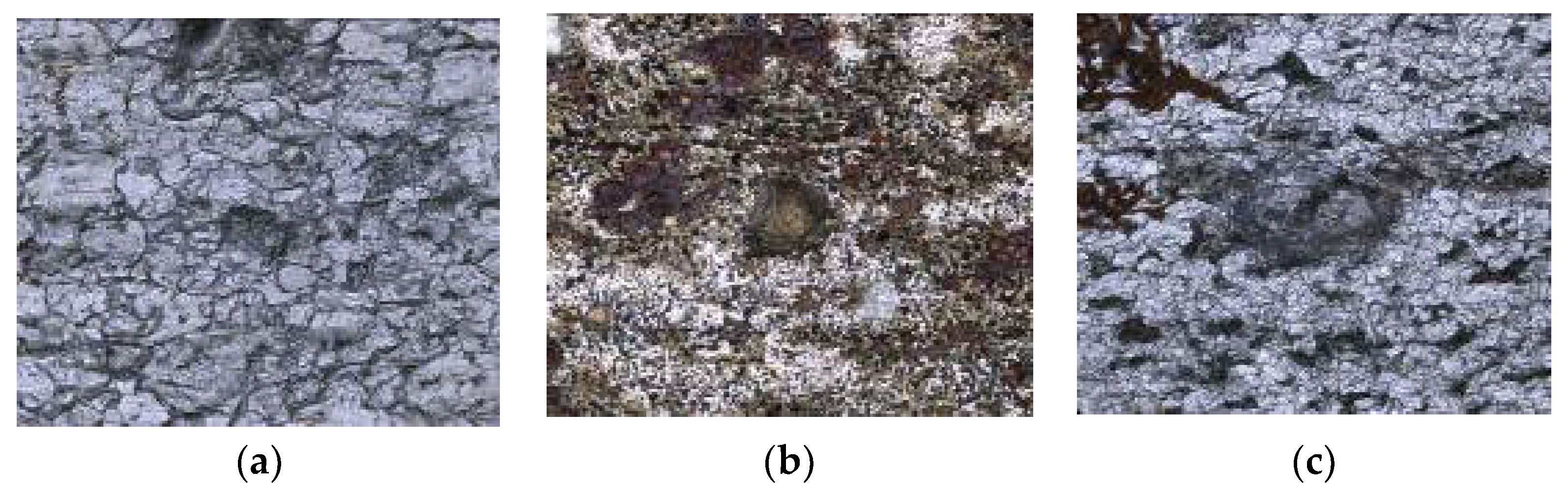
2.2.1. The Effect of CO2 on the Material of 20# Steel

Maintaining the partial pressure of H2S unchanged, the effects of the partial pressure of CO2 on the uniform corrosion and pitting were investigated. The experimental results are shown in Table 7.
It can be seen from Table 5 that with the increase of the partial pressure of CO2, the uniform corrosion rate and pitting rate increase. There are two reasons for this: with the increase of the partial pressure of CO2, the concentration of CO2 dissolved in the solution increases and the corrosivity increases. When the CO2 concentration is increased, the corrosion products on the material’s surface will change, resulting in the corresponding changes of its protective properties.
Scanning electron microscope (SEM) was used to study the microsurface morphology of the specimen. As shown in Figure 2, there are apparent pits on the surfaces of the specimens, and the pit becomes larger with the increase of the partial pressure of CO2. According to the observation of the 3-D morphology of the pits by laser scanning confocal microscope, with the increase of the partial pressure of CO2, the opening size of the pit on the surface of the specimen shows little change, but the depth is increased. In summary, the content of CO2 has a high degree of influence on the corrosion form of 20# steel.

2.2.2. The Effect of H2S on the Material of 20# Steel

Maintaining the partial pressure of CO2 unchanged, the effects of the partial pressure of H2S on the uniform corrosion and pitting were investigated. The experimental results are shown in Table 8.
It can be seen from Table 8 that with the increase of the partial pressure of H2S, the uniform corrosion rate and pitting rate increase, but the increases are not noticeable and far less than the corrosion of CO2 on the 20# steel.
The scanning electron micrographs are shown in Figure 3. It can be seen from Figure 3 that in the H2S/CO2 coexistence environment, with the rapid increase of the H2S concentration, the opening size of the corrosion pit gradually becomes larger. Results of laser scanning confocal microscope also indicated that the pitting depth is gradually deepened with the increase of the concentration of H2S. In conclusion, the content of H2S has a specific influence on the corrosion morphology and corrosion tendency of 20# steel.

2.2.3. The Effect of Cl on the Material of 20# Steel

Maintaining the partial pressure of CO2 and H2S unchanged, the effects of the concentration of Cl on the uniform corrosion and pitting were investigated. The experimental results are shown in Table 9.
It can be seen from Table 9 that with the increase of the content of Cl, the uniform corrosion rate and pitting rate increase. Among them, the increase of the uniform corrosion rate is not apparent, and the pitting rate increases.
The scanning electron micrographs are shown in Figure 4. It can be seen from Figure 4 that in the H2S/CO2 coexistence environment, the corrosion product films are loose and flaky. The corrosion pit can be seen in three kinds of solutions with different Cl concentrations. Obviously, the change of the Cl concentration does not change the microstructure of the corrosion products on the surface of the sample, indicating that the Cl content has little influence on the surface film. Results of laser scanning confocal microscope suggested that the depth of pitting deepens with the increase of the Cl concentration. Based on the above, the concentration of Cl has little effect on the surface film and the uniform corrosion rate and greatly influences the local corrosion rate.

3. Optimization of Corrosion-Resistant Metal Pipe Material

In the H2S-CO2-Cl coexisting corrosion environment system, the usual solution is to use a duplex stainless-steel pipe, but the cost of the pipe is high, and the cost of oilfield mining will be increased. Therefore, it is necessary to develop new pipe material. Steel components can be smelt using a vacuum furnace, and pipe material can be made through forging, rolling, and other processes. In addition, the mechanical properties, corrosion resistance, and welding performance of the new pipe were evaluated and compared with 20# steel.

3.1. Chemical Composition Optimization

According to the characteristics of electrochemical corrosion, the development of anticorrosive materials is mainly based on improving the potential of materials. Therefore, Cr, Cu, Mo, and other alloying elements were selected as the main objects of material optimization. The content of Cr varied from 0.5% to 2.2%. The proper addition of Cu, Mo, Nb, and other alloying elements can improve the strength and corrosion resistance. The optimized chemical composition of the material is shown in Table 10.

3.2. Mechanical Properties of Optimized Materials

The mechanical properties of 20# steel and the optimized pipe materials were tested, including the yield strength, tensile strength, extensibility, impact energy, and yield ratio, as shown in Table 11.
It can be seen in Table 11 that: (1) The strength of 20J steel (refined 20# steel) is similar to that of 20# steel, but the toughness is increased from the lowest 83 J to 139 J, which shows that the scouring effect is noticeable. (2) The Cr content of XA and XC is 0.6% and 1.1%, respectively, and the yield strength reaches 245 MPa, but the tensile strength is lower, and the impact energy is above 200 J. (3) After adding about 0.2% of Cu, the strength of the corresponding XB and XD increased, while the impact energy decreased by more than 100 J, indicating that the damage of the Cu to the toughness was apparent. (4) When the content of Cr is increased to 2%, that is, XE steel, the yield ratio decreases obviously, the bainite structure appears in the steel, and the impact energy is down to about 30 J. The strength of XF steel with the addition of grain element Nb is increased, but the impact energy is not improved. (5) Mo element is added based on XD steel, that is, the XG steel. Compared with XD steel, the strength of XG increased, and the impact energy decreased significantly. (6) XH steel is an alloy adding Mo and Cu based on Cr content 2% in the material, and the strength reaches the X80 steel grade, but the impact energy is shallow, which is a composite structure of bainite and martensite. (7) The rank of the mechanical properties of these steel materials is: XA, XC > 20J, XB, XD > 20# > XE, XF, XG, XH.

3.3. Corrosion Resistance Comparison

Immersion experiments and pressure kettle experiments were used to evaluate the corrosion resistance of the optimized materials.

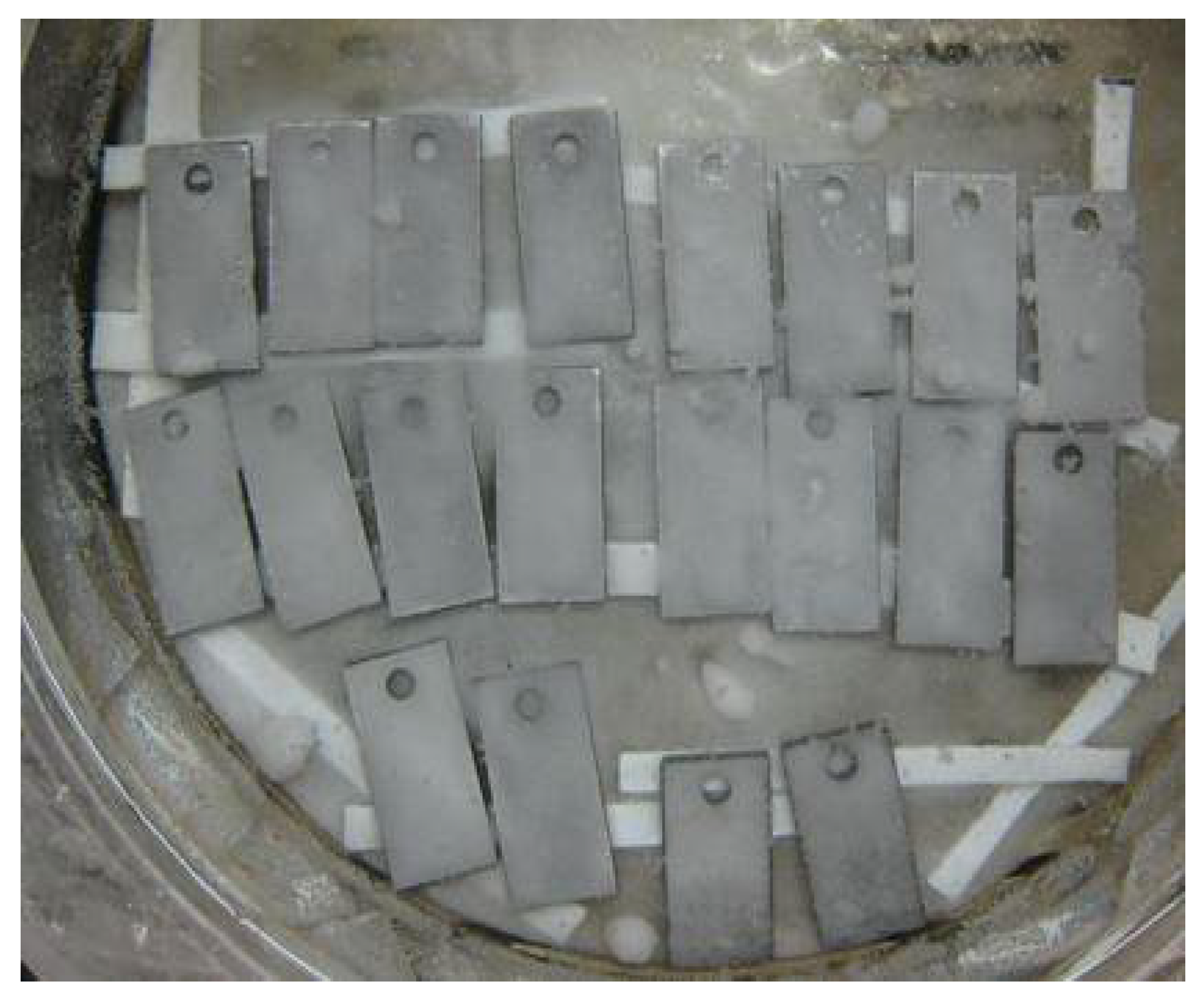
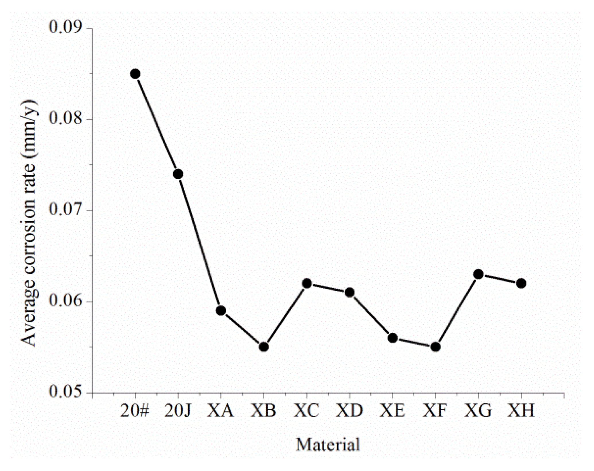
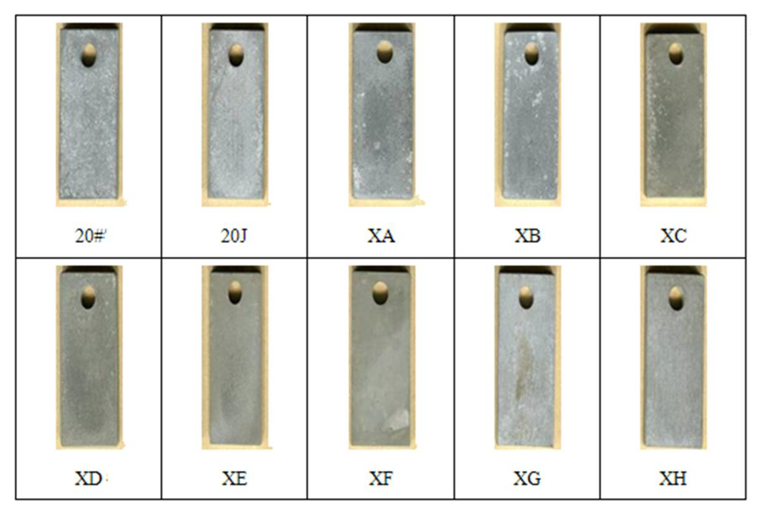
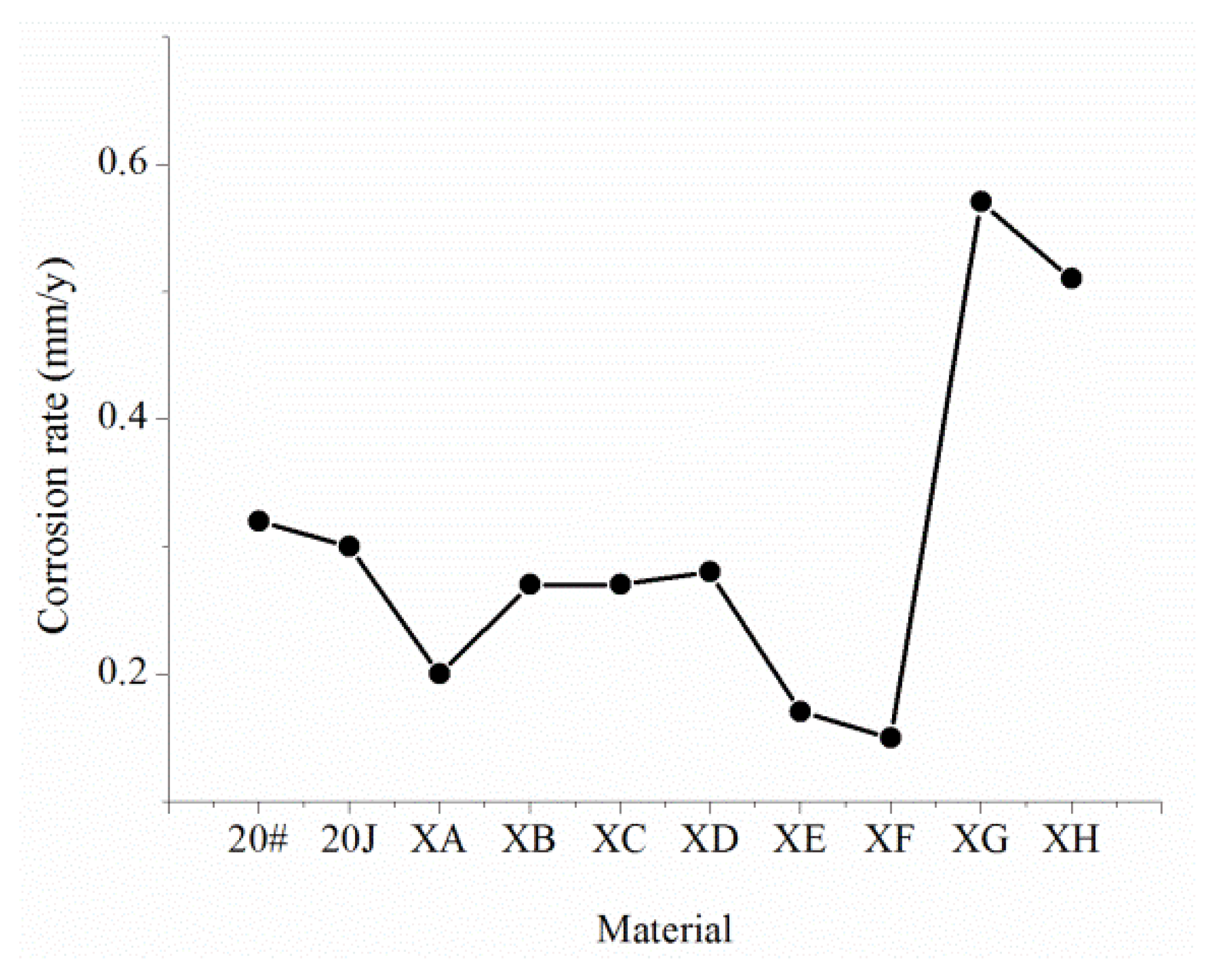
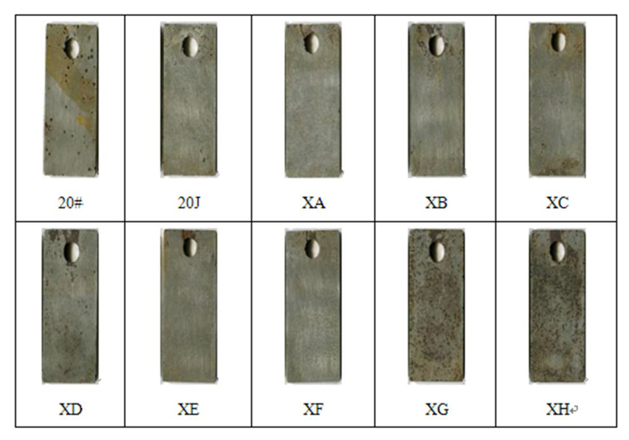
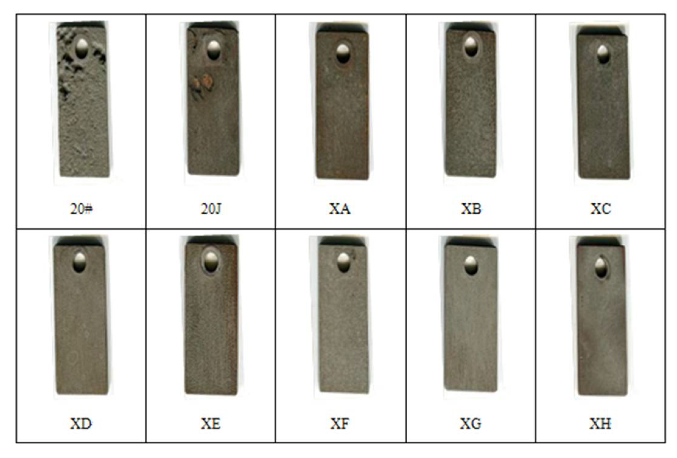
3.3.1. Immersion Experiment

Accelerated corrosion experiments include two parts: (1) Continuous access to CO2 under anaerobic condition; and (2) Aerobic condition.

Metal Coupons Were Immersed in a Solution of CO2 Partial Pressure of 0.1 MPa

According to the produced water test data of the oil field, the simulated solution (Table 12) was configured and continued to access to CO2 under the anaerobic condition, as shown in Figure 5. The duration of the experiment was 20 days, and each material had two coupons.
The average corrosion rate of the different materials is shown in Figure 6, and the specific experimental data are shown in Table A1. The morphology of coupons after the experiment can be seen in Figure 7. It can be seen from Figure 6 and Figure 7 that pitting corrosion occurred obviously in both 20# and 20J steel, and the XA and XD steel with Cr content of 0.6% and 1.1%, respectively, had a better anti pitting effect. The anti-pitting effect of XE and XF with a Cr of 2% is the best, but the corrosion loss is small, and the corrosion rate is low in this experiment.

Metal Coupons Were Immersed in a Solution of pH Value of 1.5

The pH value of the produced water in the oil field is 5.8. In order to accelerate the experimental process, the pH value was adjusted to 2.5 with hydrochloric acid and soaked for 27 days. The corrosion rate of different materials is shown in Figure 8, and the specific experimental data are shown in Table A2. The morphology of coupons after the experiment can be seen in Figure 9. It can be seen from Figure 8 and Figure 9 that obvious pitting corrosion occurred in 20# and 20J steel, but the corrosion rate was not much different from that of XA, XB, XC and XD, XE, and XF steel with a 2% Cr content only containing bainite, and the corrosion rate is low. XG and XH steel with Mo element produce martensite and the corrosion rate is larger. The pitting is more serious, indicating that the harm of unbalanced martensite tissue is greater.
Based on two immersion experiments, XG, XH, 20#, and 20J have noticeable pitting, while XA, XB, XC, and XD with a Cr content of 0.6% and 1.1% show a pitting tendency. However, compared with other steels, they have better pitting corrosion resistance.

3.3.2. Medium Pressure Kettle Experiment

Experiments were carried out using the simulated solution (Table 13). Oxygen was removed, and CO2 was introduced and maintained at a partial pressure of 1 MPa. The experimental temperature was 80 °C, the rotation speed was 1 m/s, and the experiment duration was 10 days. The corrosion rate of different materials can be seen in Figure 10, the specific experimental data of uniform corrosion are shown in Table A3, and specific experimental data of pitting corrosion are shown in Table 14. The morphology of coupons after the experiment can be seen in Figure 11.
It can be obtained from Figure 10 and Table A3 that the corrosion rates of XA and XB steel with the Cr content of 0.6% are 2.51 and 2.341 mm/year, respectively, while the corrosion rates of XC and XD steel with the Cr content of 1.1% are 1.52 mm/year, and it can be seen that the addition of a small amount of Cu (XB and XD steel) has little effect on the corrosion rate. Compared with XC steel and XD steel, the corrosion rates of XF and XF steel with a Cr content of 2.1% decrease to 1.35 mm/year, indicating that adding 1% Cr element does not substantially affect the corrosion rate. However, the corrosion rate of XG and XH steel with Mo element is lower than that of XD and XE steel; especially, the corrosion rate of XH steel is only 0.15 mm/year, which shows that Mo significantly affects CO2 corrosion resistance.
It can be seen from Table 11 that the maximum pitting depths of 20# and 20J steel are 2.99 and 0.69 mm, respectively, and the maximum pitting rates are up to 25 mm/year. The maximum pitting rates of XA and XB steel with a Cr content of 0.6% are up to 15 mm/year. Other types of steel do not show pitting corrosion, showing more typical uniform corrosion characteristics.

3.3.3. High-Pressure Kettle Experiment

The components of the simulated solution are still shown as Table 13. After oxygen was removed, CO2 (partial pressure is 1 MPa) and H2S (partial pressure is 0.1 MPa) were introduced into the high-pressure kettle at a temperature of 60 °C. Experiments were conducted using XA, XB, XC, and XD steel with a higher corrosion resistance, and the experiment duration was 10 days. The corrosion rate of different materials can be seen in Figure 12, and the morphology of coupons after the experiment can be seen in Figure 13.

3.3.4. Experimental Results

  • The corrosion resistance of 20J steel is higher than that of ordinary 20# steel, but the pitting tendency is still high, and the maximum pitting rate is up to 25 mm/year.
  • The XE and XF steel with a Cr content of 2.1% have better corrosion resistance, but the carbon equivalent of the two steels reaches 0.58. During the welding process, preheating or subsequent heat treatment is necessary, which will increase the difficulty and cost of construction.
  • Mo can effectively improve the hardenability of materials. The XH steel containing Mo exhibits an unbalanced bainitic structure and martensite structure. Although it does not affect the corrosion resistance of CO2, it is very sensitive to the corrosion of dissolved oxygen, and the tendency of pitting corrosion is pronounced.
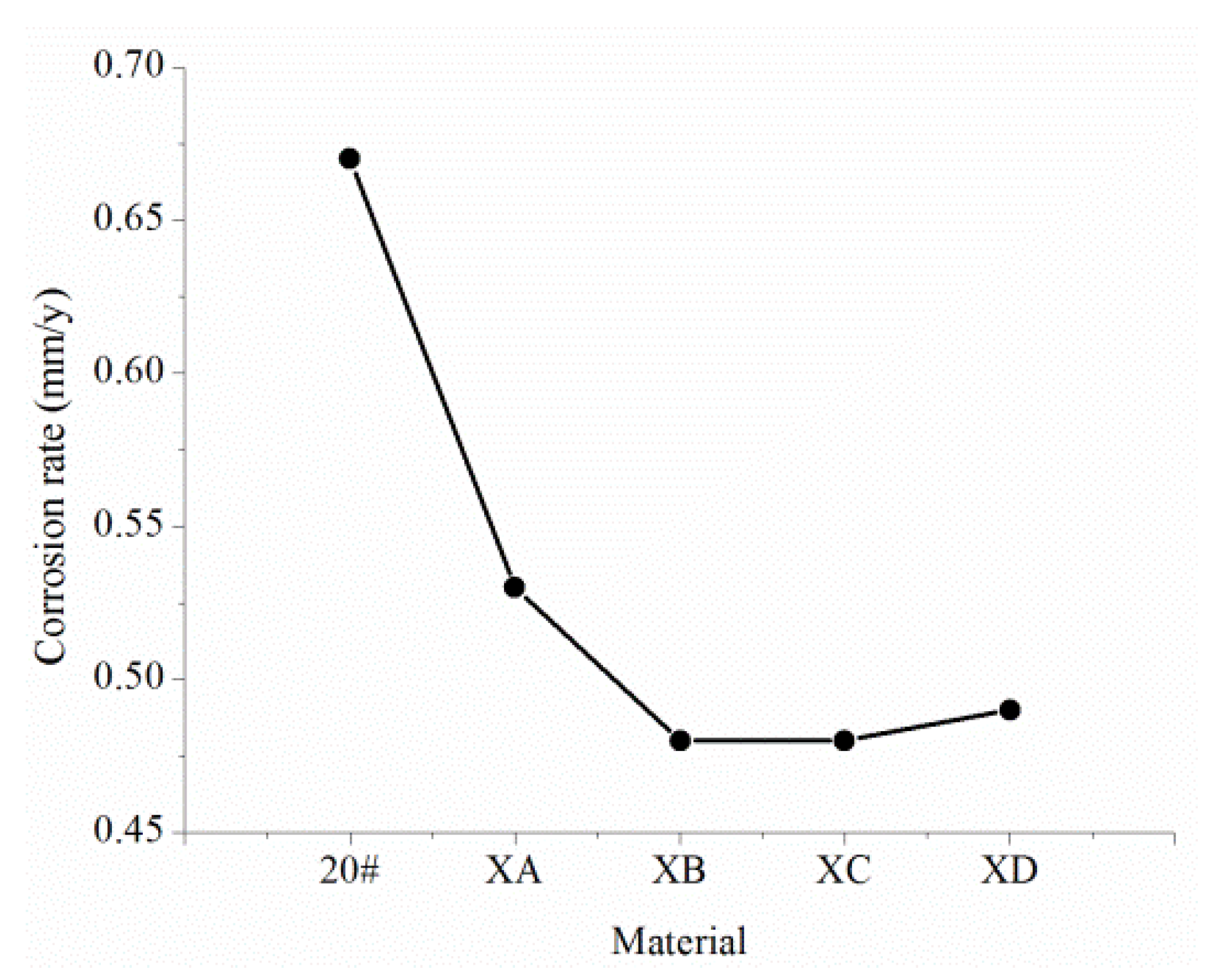
  • The XC and XB steel with a Cr content of 0.6% and the XC and XD steel with a Cr content of 1.1% all have uniform corrosion characteristics. The uniform corrosion resistance of XA and XB relative to 20# is improved by 50%, and the uniform corrosion resistance of XC and XD relative to 20# is improved by 70%. XA and XB steel have obvious pitting corrosion problems and a maximum pitting rate of 15 mm/year. Moreover, XC and XD steel do not have a pitting corrosion tendency, so they can be used as potential pipe materials for corrosion resistance.
  • The corrosion resistance of these steel materials is: XE, XF, XC, XD > XA, XB, 20J > 20# > XG, XH.

3.4. Comparison of Welding Performance

The welding performance of steel material generally refers to whether cracks are easily formed in the weld and heat-affected areas and whether the welded joints are brittle. The “carbon equivalent” is usually used to measure the quality of the welding performance. The greater the carbon equivalent, the more efficiently the weld zone produces cracks. The formula for calculating carbon equivalent Ceq is:
C e q = ω C + ω Mn 6 + ω Ni + ω Cu 15 + ω Cr + ω Mo + ω V 5
where ωC, ωMn, ωNi, ωCu, ωCr, ωMo, ωV represent the mass fraction of C, Mn, Ni, Cu, Cr, Mo, and V in the alloy, respectively, %.
Field experience shows that when the Ceq is less than 0.45%, the cold cracking tendency of the steel is not obvious, and the weldability is good. When the Ceq is between 0.45% and 0.6%, the steel tends to have a more pronounced cold cracking tendency and poor weldability, and it is necessary to preheat the steel and take other technical measures to prevent cracks in the welding; when the Ceq is greater than 0.6%, the cold cracking tendency of steel welding is pretty obvious, and the welding performance is poor, basically not suitable for welding, or only under strict process measures and high preheating temperatures for welding operation.
From Table 8, it can be concluded that the rank of weldability of these steel materials is: XA, 20J, 20#, XB, XC, XD > XG, XE, XF, XH.

3.5. Determination of New Pipe Material

Based on the evaluation of the mechanical properties, corrosion resistance, and other aspects of the new material, XC steel was selected and named as BX245-1Cr, and its chemical composition is shown in Table 15.

4. Laboratory and Field Evaluation of the New Pipe Material

In this paper, the corrosion resistance of the new material was evaluated by two methods: laboratory evaluation and field evaluation. The 20# steel and BX245-1Cr steel were used for comparison experiments. The components of the actual products of 20# steel and BX245-1Cr steel made by Baosteel company are shown in Table 16 and Figure 14, respectively.

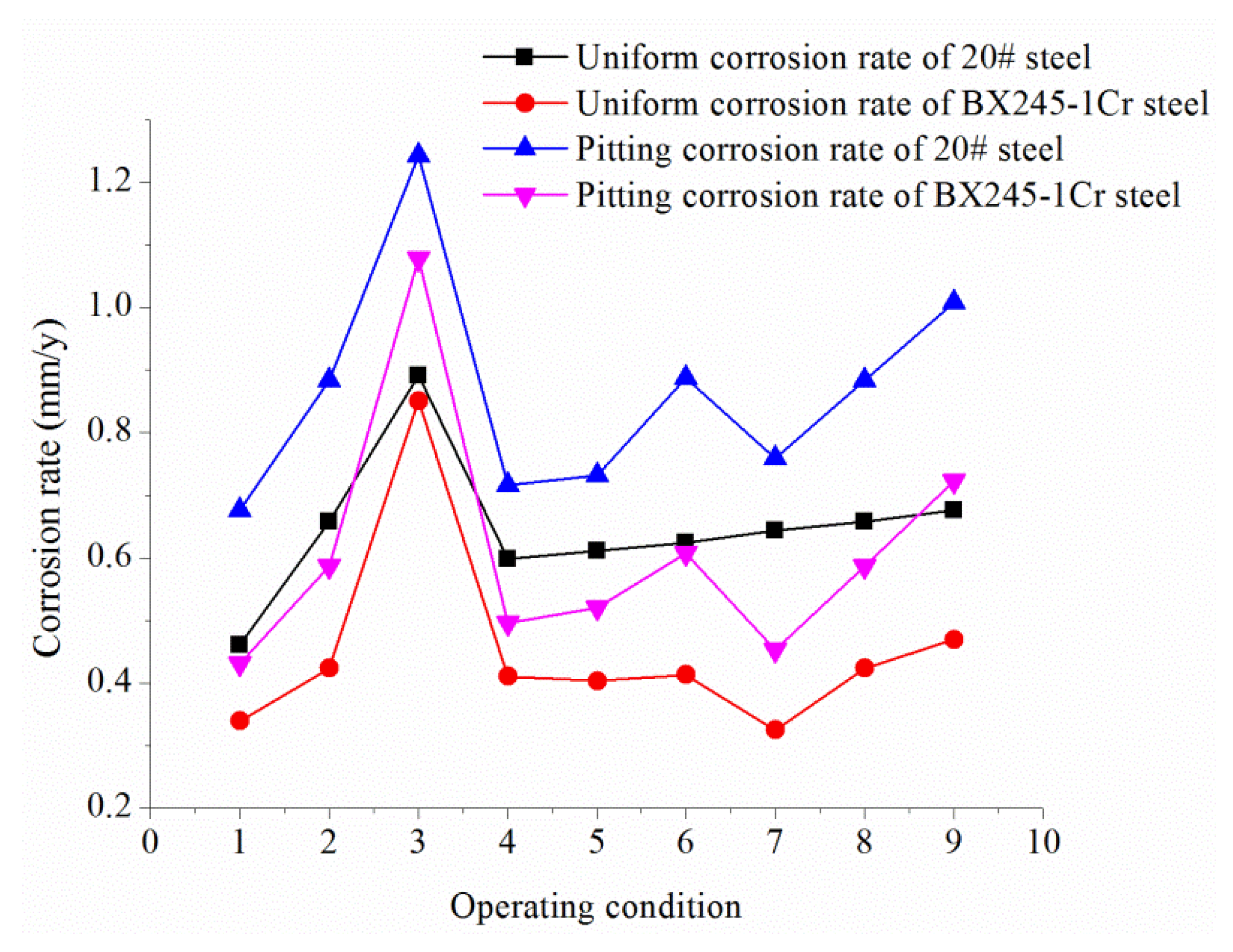
4.1. Laboratory Evaluation

The experimental parameters were designed according to the highest, average, and minimum values of the corrosion medium content in the oilfield so that the experimental results were more representative. The experimental parameters are shown in Table 17. The evaluation contents of the experiment include the rate of uniform corrosion and the rate of pitting.
Under different operating conditions, the uniform corrosion rate and pitting corrosion rate of the two metallic materials are shown in Figure 14. The microscopic corrosion morphology under different corrosive media conditions is shown in Figure 15.
From Figure 14 and Figure 15, it can be seen that the uniform corrosion rate and pitting rate of BX245-1Cr steel are smaller than that of 20# steel in all operating conditions, and the pitting pit on the surface of 20# steel is more obvious, and the pits are large and deep. While the surface of BX245-1Cr steel is relatively flat, it is dominated by uniform corrosion. Although the pitting pit is localized, the pits are small and shallow. In the H2S–CO2–Cl corrosion environment, the corrosion of 20# steel and BX245-1Cr steel is mainly caused by CO2 and H2S. Cl participates in the whole electrochemical corrosion reaction process, but it does not constitute the corrosion product while Cl only plays the role of catalyst. Under the simulated experimental conditions, the uniform corrosion resistance of BX245-1Cr steel is 30.25% higher than that of 20# steel, and the pitting corrosion resistance of BX245-1Cr steel is 29.66% higher than that of 20# steel.

4.2. Field Evaluation

Field evaluation still adopts the coupon (Size: 50 mm × 13 mm × 1.5 mm) experiment. In the oil, gas, water systems of Northwest Oil and Gas Field, 24 monitoring points were selected for real-time monitoring. The monitoring points are located in the more severe pipe corrosion areas in the northwest oil and gas fields, including where (1) corrosion perforation occurred; (2) the corrosion rate is moderate and above; (3) the corrosion environment is horrible; and (4) sewerage system monitoring points.
The total monitoring period was 240 days, which can be divided into Phase I (30 days), Phase II (90 days), and Phase III (120 days). In order to make the monitoring data more in line with the actual situation, the coupons of Phase I were brand new. In Phase II, after coupons’ data analysis of Phase I was completed, the original monitoring point was returned to. In Phase III, after coupons’ data analysis of Phase II was completed, and the original monitoring point was returned to. The corrosion rate was calculated from the average of 24 coupons’ corrosion rate. The experimental results are shown in Table 18.
It can be obtained from Table 18 that the uniform corrosion rate and pitting rate of BX245-1Cr steel are smaller than those of 20# steel, and the pitting corrosion resistance of BX245-1Cr steel is more obvious. The corrosion rates of the two materials in Phase II are lower than that of Phase I, because of the dissolution of Cr in the BX245-1Cr material, the corrosion product film, which is mainly the amorphous substance Cr(OH)3, is formed on the metal surface. The corrosion product film has a specific anion selectivity, which can effectively prevent the anion from penetrating the corrosion product film to the metal surface, reducing the anion concentration at the interface between the film and the metal, thereby reducing the corrosion rate of the metal. However, before Phase III, the corrosion product film, which is mainly composed of Cr(OH)3 on the surface of the coupon, is removed, resulting in partial damage of the corrosion product film on the metal surface, then put in the corrosion medium again, and the corrosion rate is accelerated.

5. Conclusions

Aiming at the corrosion problem of pipelines in Tahe Oilfield, this paper conducted an in-depth study on the corrosion laws of pipelines. In this paper, indoor tests were carried out from the aspects of the corrosive environment and operating conditions, the main factors of corrosion were studied, and the corrosion law of metal pipeline in different corrosive media was clarified. On this basis, a new material was proposed. The main conclusions are as follows:
  • In the H2S–CO2–Cl corrosion environment, H2O is the carrier of corrosion, Cl is the corrosion catalyst, H2S is a strong hydrogen permeation medium, CO2 dissolves in water to cause electrochemical corrosion, and O2 is a kind of depolarization agent.
  • The content of CO2 has a significant influence on the corrosion form of 20# steel; the content of H2S has a certain influence on the corrosion morphology and corrosion tendency of 20# steel, and the concentration of Cl has a great influence on the local corrosion rate but little effect on the surface film and the uniform corrosion rate.
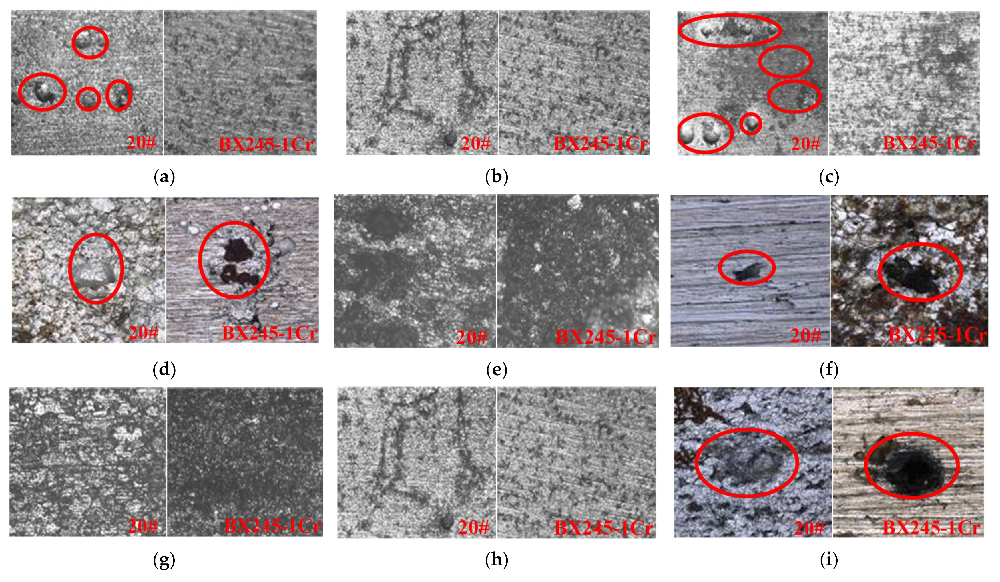
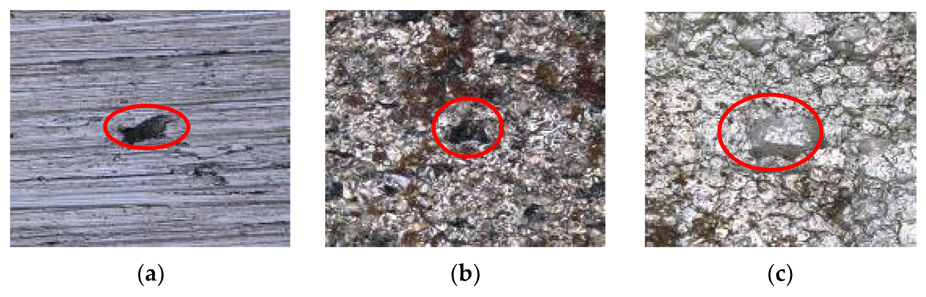
  • Under the simulated experimental conditions, the uniform corrosion resistance and the pitting corrosion resistance of BX245-1Cr steel was 30.25% and 29.66% higher than that of 20# steel, which means BX245-1Cr steel has better resistance to pitting corrosion.
The problem of pitting corrosion was analyzed in this paper. However, combined with engineering practice, in the future work, more in-depth research will be carried out from two aspects: (1) the corrosion mechanism of wet H2S, and (2) the fracture mechanism of new materials in a corrosive environment. In addition, under the background of artificial intelligence, some new materials can be developed by machine learning [19].

Author Contributions

Conceptualization, X.S. and X.L.; methodology, X.S. and Z.Z. (Zhi Zhang); software, L.W. and X.L.; investigation, X.L. and Z.Z. (Zhenwu Zhang); resources, X.S. and L.W.; data curation, L.W. and Z.Z. (Zhi Zhang); writing—original draft preparation, X.S. and Z.Z. (Zhenwu Zhang); writing—review and editing, Z.Z. (Zhi Zhang) and L.W.; supervision, X.S.; project administration, X.L.; All authors have read and agreed to the published version of the manuscript.

Funding

This research received no external funding.

Institutional Review Board Statement

Not applicable.

Informed Consent Statement

Not applicable.

Data Availability Statement

Not applicable.

Conflicts of Interest

The authors declare no conflict of interest.

Appendix A

Table A1. Average corrosion rate in the case of CO2 partial pressure of 0.1 MPa.
MaterialSurface Area of Coupon (m2)Weighing before the Experiment (g)Weighing after the Experiment (g)Weight Loss (g)Corrosion Rate (mm/year)Average Corrosion Rate (mm/year)
20#0.00288427.996227.88600.11020.0890.085
0.00288427.485927.38540.10050.081
20J0.00288427.436727.35230.08440.0680.074
0.00288426.387026.28750.09950.080
XA0.00288427.817927.74740.07050.0570.059
0.00288427.834027.75890.07510.060
XB0.00288428.080428.02910.05130.0410.055
0.00288428.241128.15540.08570.069
XC0.00288427.887527.79900.08850.0710.062
0.00288427.642627.57800.06460.052
XD0.00288427.811327.73860.07270.0590.061
0.00288427.854227.77480.07940.064
XE0.00288427.618727.54880.06990.0560.056
0.00288427.316927.24650.07040.057
XF0.00288427.895827.84690.04890.0390.055
0.00288428.022427.93590.08650.070
XG0.00288427.689927.60750.08240.0660.063
0.00288427.884027.80880.07520.061
XH0.00288427.359927.28790.0720.0580.062
0.00288427.677527.59430.08320.067
Table A2. Corrosion rate in the case of pH value of 2.5.
MaterialSurface Area of Coupon (m2)Weighing before the Experiment (g)Weighing after the Experiment (g)Weight Loss (g)Corrosion Rate (mm/year)
20#0.00288428.652328.13800.51430.32
20J0.00288427.573627.08870.48490.30
XA0.00288428.280127.97000.31010.20
XB0.00288428.449528.01120.43830.27
XC0.00288428.294027.85120.44280.27
XD0.00288428.455927.99130.46460.28
XE0.00288428.190627.90800.28260.17
XF0.00288428.211327.96540.24590.15
XG0.00288428.211627.28030.93130.57
XH0.00288428.165327.33930.8260.51
Table A3. Corrosion rate in the case of CO2 partial pressure of 1 MPa and 80 °C.
MaterialSurface Area of Coupon (m2)Weighing before the Experiment (g)Weighing after the Experiment (g)Weight Loss (g)Corrosion Rate (mm/year)
20#0.00288428.203422.10556.09794.91
20J0.00288426.869522.78864.08093.29
XA0.00288427.996624.87593.12072.51
XB0.00288428.210925.30802.90292.34
XC0.00288427.797725.91001.88771.52
XD0.00288428.062426.17371.88871.52
XE0.00288427.847726.12191.72581.39
XF0.00288427.916326.23801.67831.35
XG0.00288427.949326.32951.61981.30
XH0.00288427.771027.58410.18690.15

References

  1. Lu, H.; Iseley, T.; Matthews, J.; Liao, W. Hybrid machine learning for pullback force forecasting during horizontal directional drilling. Autom. Constr. 2021, 129, 103810. [Google Scholar] [CrossRef]
  2. Xu, Z.D.; Zhu, C.; Shao, L.W. Damage identification of pipeline based on ultrasonic guided wave and wavelet denoising. J. Pipeline Syst. Eng. Pract. 2021, 12, 04021051. [Google Scholar] [CrossRef]
  3. Xu, Z.D.; Yang, Y.; Miao, A.N. Dynamic analysis and parameter optimization of pipelines with multidimensional vibration isolation and mitigation device. J. Pipeline Syst. Eng. Pract. 2021, 12, 04020058. [Google Scholar] [CrossRef]
  4. Lu, H.; Xu, Z.D.; Iseley, T.; Matthews, J.C. Novel data-driven framework for predicting residual strength of corroded pipelines. J. Pipeline Syst. Eng. Pract. 2021, 12, 04021045. [Google Scholar] [CrossRef]
  5. Lu, H.; Iseley, T.; Matthews, J.; Liao, W.; Azimi, M. An ensemble model based on relevance vector machine and multi-objective salp swarm algorithm for predicting burst pressure of corroded pipelines. J. Pet. Sci. Eng. 2021, 203, 108585. [Google Scholar] [CrossRef]
  6. Yang, D.; Ge, P.; Zhu, Y. Corrosion prevention and control technology application of gathering and transportation pipelines in Tahe oilfield. Surf. Technol. 2016, 45, 57–64. [Google Scholar]
  7. Rogers, W.F.; Rowe, A., Jr. 3. Corrosion effects of hydrogen sulphide and carbon dioxide in oil production. In Proceedings of the 4th World Petroleum Congress, Rome, Italy, 6–15 June 1955. [Google Scholar]
  8. Kermani, B.; Dougan, M.; Gonzalez, J.C.; Linne, C.; Cochrane, R. Development of low carbon Cr–Mo steels with exceptional corrosion resistance for oilfield applications. In Proceedings of the CORROSION, Houston, TX, USA, 11–16 March 2001. [Google Scholar]
  9. Kermani, B.; Gonzales, J.C.; Turconi, G.L.; Pigliacampo, L.; Perez, T.; Morales, C. Window of application and operational track record of low carbon 3Cr steel tubular. In Proceedings of the CORROSION, San Diego, CA, USA, 12–16 March 2006. [Google Scholar]
  10. Liu, H.X.; Zhang, G.L.; Zhao, J.M.; Liu, D.Y. Corrosion behaviors of four steels in CO2-saturated brine. Corros. Prot. 2007, 28, 202–204. [Google Scholar]
  11. Ding, J.; Zhang, L.; Li, D.; Lu, M.; Xue, J.; Zhong, W. Corrosion and stress corrosion cracking behavior of 316L austenitic stainless steel in high H2S–CO2–Cl environment. J. Mater. Sci. 2013, 48, 3708–3715. [Google Scholar] [CrossRef]
  12. Li, D.P.; Zhang, L.; Yang, J.W.; Lu, M.X.; Ding, J.H.; Liu, M.L. Effect of H2S concentration on the corrosion behavior of pipeline steel under the coexistence of H2S and CO2. Int. J. Miner. Metall. Mater. 2014, 21, 388–394. [Google Scholar] [CrossRef]
  13. Guo, Z.J.; Chen, D.F.; Li, Y.J.; Li, X.J.; Xuan, P.C.; Mao, Z.Q.; Xie, S. research progress of oil field pressure vessel corrosion mechanisms in H2S-CO2-Cl environment. J. Petro-Chem. Equip. 2008, 37, 53–58. [Google Scholar]
  14. Zhou, J.; Li, Y. Anodic electrochemical behavior of X80 pipeline steel in NaHCO3 solution. Acta Met. Sin 2010, 46, 251–256. [Google Scholar] [CrossRef]
  15. Xia, X. Stress corrosion-induced cracking of 20 steel in H2S solution. Mater. Prot. 2007, 40, 15–17. [Google Scholar]
  16. Lu, J.Z.; Wang, B.; Zhang, D.F.; Zhou, D.M. Corrosion mechanism research of 20G steel in high Cl glycol solution. Press. Vessel. Technol. 2010, 27, 19–23. [Google Scholar]
  17. Pots, B.F.; Kapusta, S.D.; John, R.C.; Thomas, M.J.J.; Rippon, I.J.; Whitham, T.S.; Girgis, M. Improvements on de Waard-Milliams corrosion prediction and applications to corrosion management. In Proceedings of the CORROSION 2002, Denver, CO, USA, 7–11 April 2002. [Google Scholar]
  18. NACE RP0775, Preparation, Installation, Analysis, and Interpretation of Corrosion Coupons in Oilfield Operations; NACE International: Houston, TX, USA, 2005.
  19. Lu, H.; Behbahani, S.; Ma, X.; Iseley, T. A multi-objective optimizer-based model for predicting composite material properties. Constr. Build. Mater. 2021, 284, 122746. [Google Scholar] [CrossRef]
Figure 1. The typical corrosion morphology of the pipes in Tahe Oilfield.
Coatings 11 01269 g001
Figure 2. Scanning electron micrographs of pits (×25 times) (a) PCO2 = 0.01 MPa; (b) PCO2 = 0.15 MPa; (c) PCO2 = 0.45 MPa.
Coatings 11 01269 g002
Figure 3. Scanning electron micrographs of pits (×25 times) (a) PH2S = 0.0003 MPa; (b) PH2S = 0.0008 MPa; (c) PH2S = 0.003 MPa.
Coatings 11 01269 g003
Figure 4. Scanning electron micrographs of pits (×25 times): (a) Cl = 60,000 mg/L; (b) Cl = 110,000 mg/L; (c) Cl = 150,000 mg/L.
Coatings 11 01269 g004
Figure 5. Metal coupon soaked in the simulated solution.
Coatings 11 01269 g005
Figure 6. Average corrosion rate of different materials.
Coatings 11 01269 g006
Figure 7. Morphology of coupons after the experiment.
Coatings 11 01269 g007
Figure 8. Corrosion rate of different materials.
Coatings 11 01269 g008
Figure 9. Morphology of coupons after the experiment.
Coatings 11 01269 g009
Figure 10. Corrosion rate of different materials.
Coatings 11 01269 g010
Figure 11. Morphology of coupons after the experiment.
Coatings 11 01269 g011
Figure 12. Corrosion rate of different materials.
Coatings 11 01269 g012
Figure 13. Morphology of coupons after the experiment.
Coatings 11 01269 g013
Figure 14. Corrosion rate of 20# steel and BX245-1Cr steel.
Coatings 11 01269 g014
Figure 15. Microscopic corrosion morphology (×25 times) (a) Partial pressure of CO2 = 0.01 MPa; (b) Partial pressure of CO2 = 0.15 MPa; (c) Partial pressure of CO2 = 0.45 MPa; (d) Partial pressure of H2S = 0.0003 MPa; (e) Partial pressure of H2S = 0.0008 MPa; (f) Partial pressure of H2S = 0.003 MPa; (g) Concentration of Cl = 60,000 mg/L; (h) Concentration of Cl = 110,000 mg/L; (i) Concentration of Cl = 150,000 mg/L.
Coatings 11 01269 g015
Table 1. The content of the corrosion medium in the field.
MediumMinimum ValueMaximum ValueAverage Value
H2S2.4 mg/m3170,571 mg/m338,962 mg/m3
CO24.88%27.2%8.07%
Cl60,929 mg/L150,325 mg/L113,316 mg/L
Table 2. Composition of the formation water.
Cl (mg/L)SO42− (mg/L)Ca2+ (mg/L)Mg2+ (mg/L)HCO3 (mg/L)Total MineralizationPH Value
113,316302.716,460.3955.4620.4189,2876.0
Table 3. Experimental conditions 1.
Partial Pressure of CO2 (MPa)Partial Pressure of H2S (MPa)PCO2/PH2SConcentration of Cl (mg/L)Temperature
(°C)
Total Pressure
(MPa)
Test Cycle (days)
0.010.040.25110,000701.630
0.153.75
0.4511.25
Table 4. Experimental conditions 2.
Partial Pressure of CO2 (MPa)Partial Pressure of H2S (MPa)PCO2/PH2SConcentration of Cl (mg/L)Temperature (°C)Total Pressure (MPa)Test Cycle (days)
0.150.00350110,000701.630
0.0008200
0.0003450
Table 5. Experimental conditions 3.
Partial Pressure of CO2 (MPa)Partial Pressure of H2S (MPa)PCO2/PH2SConcentration of Cl (mg/L)Temperature (°C)Total Pressure (MPa)Test Cycle (days)
0.150.043.7560,000701.630
110,000
150,000
Table 6. Corrosion grade for the oil production system.
GradeUniform Corrosion Rate (mm/year)Maximum Pitting Rate (mm/year)
Low<0.025<0.13
Moderate0.025–0.120.13–0.20
High0.13–0.250.21–0.38
Severe>0.25>0.38
Table 7. Experimental results of the experimental conditions 1.
Partial Pressure of CO2 (MPa)Partial Pressure of H2S (MPa)Uniform Corrosion RatePitting Rate
Value (mm/year)Grade of CorrosionValue (mm/year)Grade of Corrosion
0.010.040.4605Severe0.6765Severe
0.150.6572Severe0.8835Severe
0.450.8913Severe1.2435Severe
Table 8. Experimental results of experimental conditions 2.
Partial Pressure of CO2 (MPa)Partial Pressure of H2S (MPa)Uniform Corrosion RatePitting Rate
Value (mm/year)Grade of CorrosionValue (mm/year)Grade of Corrosion
0.150.00030.5984Severe0.7166Severe
0.0080.6105Severe0.7324Severe
0.0030.6235Severe0.8877Severe
Table 9. Experimental results of experimental conditions 3.
Partial Pressure of CO2 (MPa)Partial Pressure of H2S (MPa)Content of Cl (mg/L)Uniform Corrosion RatePitting Rate
Value (mm/year)Grade
of Corrosion
Value (mm/year)Grade
of Corrosion
0.150.0460,0000.6438Severe0.7585Severe
110,0000.6572Severe0.8835Severe
150,0000.6760Severe1.0081Severe
Table 10. Compositions of 20# steel and optimized steel.
MaterialC (%)Si (%)Mn (%)P (%)S (%)Cr (%)Cu (%)Nb (%)Mo (%)Carbon Equivalent (%)
20#0.230.260.490.0140.009----0.31
20J0.200.300.510.0090.001----0.29
XA0.070.290.480.0070.0020.65---0.25
XB0.090.340.520.0090.0020.630.18--0.31
XC0.070.330.510.0060.0021.09---0.37
XD0.090.310.510.0090.0031.110.23--0.41
XE0.080.340.520.0100.0022.08---0.58
XF0.080.330.530.0090.0032.1-0.04-0.59
XG0.080.350.500.0090.0021.090.21-0.230.44
XH0.090.330.510.0080.0022.110.21-0.240.65
Table 11. Mechanical properties of 20# steel and optimized steel.
MaterialYield Strength (MPa)Tensile Strength (MPa)Extensibility (%)Impact Energy (J) (0 °C)Yield RatioMetallographic Structure
20#30846928.583, 90, 870.67F 1 + P 1
20J28845436.5153, 177, 1390.63F + P
XA25139043.5233, 240, 2360.64F + P
XB28644636.5109, 109, 940.64F + P
XC26640443.0281, 274, 2740.66F + P
XD29449136135, 120, 1160.60F + P
XE24850136.041, 34, 260.50F + B 1
XF36760725.028, 16, 230.60F + B
XG36660625.515, 15, 160.60F + B + M 1
XH5658512211, 9, 100.66B + M
1 In Table 9, F represents ferrite, P represents pearlite, B represents bainite, and M represents martensite.
Table 12. Simulated solution of the oil field.
Icon Content (mg/L)CO2 Partial Pressure (MPa)Experimental Duration (h)
K+, Na+Ca2+Mg2+ClSO42−HCO30.1480
71,99315,0001298134,345300113
Table 13. Formulation of simulated solution.
CompositionNaClKClMgCl2CaCl2Na2SO4NaHCO3PH Value
Content (g/L)154.9320.975.1441.630.440.1564.5
Table 14. Pitting rate in the case of CO2 partial pressure of 1 MPa and 80 °C.
MaterialMaximum Pitting Depth (mm)Average Pitting Depth (mm)Maximum Pitting Rate (mm/year)Average Pitting Rate (mm/year)
20#2.9902.914109.135106.361
20J0.6900.57825.18521.097
XA0.4400.15216.0605.548
XB0.4300.30215.69511.023
XCNo pitting phenomenon
XD
XE
XF
XG
XH
Table 15. Chemical composition of BX245-1Cr steel.
CompositionCSiMnPSCr
Mass fraction (%)0.06–0.090.25–0.350.4–0.6≤0.015≤0.0030.01–0.012
Table 16. The components of the actual products of 20# steel and BX245-1Cr steel.
SteelCSiMnPSCrNiCu
20#0.210.320.520.0320.0350.210.230.22
BX245-1Cr0.070.300.50.0070.00110.011--
Table 17. Experimental parameters.
ConditionPartial Pressure of CO2 (MPa)Partial Pressure of H2S (MPa)Concentration of Cl (mg/L)Total Pressure (MPa)Temperature (°C)Experimental Duration (days)Flow Rate (m/s)
10.010.04110,000701.6301
20.150.04110,000701.6301
30.450.04110,000701.6301
40.150.0003110,000701.6301
50.150.0008110,000701.6301
60.150.003110,000701.6301
70.150.0460,000701.6301
80.150.04110,000701.6301
90.150.04150,000701.6301
Table 18. Corrosion rate monitoring results.
PhaseUniform Corrosion Rate (mm/year)Corrosion rate Decline (%)Pitting Corrosion Rate (mm/year)Corrosion Rate Decline (%)
BX245-1Cr20#BX245-1Cr20#
I0.02700.02948.160.32240.565943.03
II0.00910.010513.330.10240.121715.86
III0.06170.06332.530.25850.403235.89
Average0.02350.0258.010.24630.371731.59
Publisher’s Note: MDPI stays neutral with regard to jurisdictional claims in published maps and institutional affiliations.

