Article

Microstructure and Mechanical Properties of Multiple In-Situ-Phases-Reinforced Nickel Composite Coatings Deposited by Wide-Band Laser

1
Key Laboratory of Green Fabrication and Surface Technology of Advanced Metal Materials, Anhui University of Technology, Ministry of Education, Ma’anshan 243002, China
2
School of Materials Science and Engineering, Anhui University of Technology, Ma’anshan 243032, China
3
Materials and Energy Division, Beijing Computational Science Research Center, Beijing 100193, China
*
Authors to whom correspondence should be addressed.
Coatings 2021, 11(1), 36; https://doi.org/10.3390/coatings11010036
Submission received: 1 December 2020 / Revised: 23 December 2020 / Accepted: 29 December 2020 / Published: 1 January 2021

Abstract

:
Metal matrix ceramic composites (MMCs) are widely applied materials in surface engineering due to their high hardness and excellent wear resistance. Recently, various MMCs have been successfully fabricated by a promising method named direct laser deposition. In this work, nickel-based hard surface coatings reinforced with multiple in-situ phases were deposited by wide-band laser. The strengthened phases were synthesized by varied content of Ti and B4C precursor powders. The microstructure evolution, phase constitution and mechanical properties of the designed coatings were investigated. Results indicated the B4C were decomposed and free C and B atoms were released in a molten pool. Multiple secondary phases such as TiC, Cr7C3, Cr23C6, TiB and CrB were in-situ synthesized. As the content of precursor Ti and B4C powders increased, the microstructure of the laser-clad coatings was greatly refined due to the plentiful in-situ phases. Mechanical properties of the coatings revealed the maximum elastic modulus and microhardness reached 247 and 7.18 GPa in the experiment group. Friction tests indicated the average friction coefficient of optimized coating was about 0.50.

1. Introduction

Metal matrix ceramic composites (MMCs) have been one of the most important surface hardening materials in engineering [1,2,3]. MMCs are mainly composed of a metal matrix which act as the binder phase and hard ceramic particles which are the strengthening phases [4,5]. Recently, various MMC coatings have been successfully applied to modify the surface performances of engineering steels such as the hardness, wear resistance, corrosion resistance, oxidation resistance, etc. [6,7,8]. Generally, the ceramic particles in MMCs are induced by extra addition or in-situ synthesis. Former researchers have proved that the in-situ-synthesized ceramic particles have advantages of homogeneous distribution, high density, dense bonding and flexible design [9,10,11]. The carbides and borides with high hardness and modulus including NbC [12], Cr3C2 [13], TiC [14], TiB2 [15] et al. can be synthesized by in-situ reactions. For instance, Y. Hu fabricated the TiB-reinforced titanium matrix composites (TiB-TMCs) by in-situ-laser-engineered net shaping, and improved the hardness of the Ti matrix [16]. Verdi et al. deposited a MMC Inconel625-Cr3C2 coating by laser cladding onto ferritic steel [13]. The in-situ-formed Cr7C3 carbides dramatically improved the hardness of the coatings.
Traditionally, MMCs can be synthesized by sintering, ball milling, powder metallurgy, casting and other technologies. Among these techniques, the rapidly developed laser processing technology has become one of the most promising methods. Due to the development of the laser industry, various lasers such as CO2 laser, Nd: YAG (Neodymium-Doped Yttrium Aluminum Garnet) laser and fiber laser have been successfully applied in the materials processing technologies [17]. Laser cladding, laser welding, laser metal deposition, selected laser melting and also the research hot spot, laser additive manufacturing or laser 3D printing, have been rapidly developed in the last decades [18,19,20]. It is noted that a large number of scholars have carried out research on enhancing the surface properties of low-cost alloys through laser-cladding-deposited MMCs. Laser cladding, also known as direct laser deposition, is a promising technology in surface engineering [21]. Composite powders of metal and reinforcement can be melted by laser irradiation and then solidified on surface of steels. Since the temperature of laser molten pool is rather high, in-situ reactions could be highly promoted. Due to the rather high cooling rate, the microstructure of the solidified metal also can be greatly refined. Coatings made by laser cladding have the advantages of high deposition rate, dense metallurgical bonding, good wear resistance and flexible chemical composition.
Recently, the multiple ceramic phases induced by the in-situ reactions in MMCs have drawn more and more attention of researchers. Precursor materials such as B4C powders are regarded as a potential reactant in high temperature liquid metal. Bai reported on TiNi-based coatings reinforced by different contents of B4C [22]. Results indicated large amounts of TiC and TiB2 phases were in-situ-synthesized and the coating hardness increased as the content of B4C raised. However, the in-situ reactions were strongly dependent on the laser cladding parameters. In the research of Yilbas, the added B4C powders were kept stable and remained as the final strengthening phases due to the lower power of the laser irradiation [23]. Recently, the modified wide-band diode laser has been widely applied in the laser cladding process [24]. The rectangular laser spot has the advantages of uniform energy distribution, high deposition efficiency and a stabilized temperature field [25]. Due to the unique temperature and liquid flow characteristics in a laser pool, the dissolution and mass transfer of precursor materials varies, and thus affects the in-situ reactions of reinforced phases [26,27]. Although much literature has reported on MMC coatings reinforced with B4C, it is still interesting to study the unique characteristics of microstructure evolution and properties in coatings deposited by wide-band laser.
In this work, a series of Ni–Cr–Fe–Si–B coatings mixed with different contents of Ti and B4C powders were deposited on surfaces of low alloy steels by wide-band laser. This research aims to explain the essential relationship between the microstructure evolution, phase constitution and mechanical properties of coatings deposited by wide-band laser.

2. Materials and Methods

2.1. Materials

Q550 high strength, low alloy steel (HSLA, GB/T17951-2008 [7]) is used as a substrate in these experiments. The chemical composition of base steel (in wt.%) is C 0.18, Mn 2.00, Cr 0.80, Ni 0.80, Cu 0.80, Si 0.60 and Fe in balance. The microstructure of Q550 steel consists of low carbon bainite and lath martensite. The base metals were cut by an electro-discharge cutting machine with dimensions of 60 mm × 20 mm. The thickness of base steel is 10 mm. The cladding materials include Ni–Cr–Fe–Si–B self-fluxing powders (Ni60, zhzm Co., Ltd., Xingtai, China), Ti powders (Ti1, zhzm Co., Ltd., Xingtai, China) and B4C powders (pure 99.8%, zyxd Co., Ltd., Xingtai, China). The chemical composition of Ni–Cr–Fe–Si–B self-fluxing powders (in wt.%) is C 0.85, B 3.60, Si 4.50, Fe 14.0, Cr 16.0 and Ni in balance. Firstly, the Ti powders and B4C powders were mixed in molar ratio 3:1. Then the mixture was added into Ni–Cr–Fe–Si–B self-fluxing powders and uniformly mixed by mechanical stirring. The weight percent of Ti and B4C was 2.0%, 5.0% and 10.0% in coating 1#, coating 2# and coating 3# respectively. Prior to the laser cladding process, the mixed powders were prepared on the surface of a specimen with thickness of 1.0 mm using alcohol as a binder.

2.2. Laser Cladding Process

The laser cladding progress was conducted utilizing a diode laser (LDF4000-100, Laserline Gmbh, Mülheim-Kärlich, Germany). The output laser is a wide-band beam with dimensions of 17 mm × 1.5 mm. As described in former literature, the energy distribution in wide-band laser spot is a near flat top laser beam (FTLB). The optimized parameters ensure to obtain a coating with perfect bonding as follows: laser power 3.0 kW, laser scanning speed 3.0 mm/s. During laser cladding, the laser pool was protected from oxidation using pure Ar (99.9%) as a shielding gas at the flow rate of 12 L/min.

2.3. Materials Characterization

Phase compositions of composite coatings were examined by X-ray diffraction (XRD, D8advance, Rigaku, Tokyo, Japan). The parameters of X-ray diffraction were set as follows: 40 kV, 15 mA, Cu Kα radiation, scanning speed 10°/min, and scanning angle 10°–90°. The microstructure and elemental distribution was studied by field emission scanning electron microscope (FE-SEM, NANO430, FEI, Hillsboro, OR, USA) and energy dispersive spectroscopy (EDS, X-max20, Oxford Instruments, Oxford, UK). The in-situ-synthesized phases were extracted and then examined by high-resolution transmission electron microscopy (HR-TEM, JEM2100, JEOL, Tokyo, Japan). Nanoindentation tests were carried out using a nanoindentor (Nano Indenter G200, Agilent, Santa Clara, CA, USA). Additional specifications of the instrument provide for a displacement resolution of 0.01 nm and a load resolution of 50 nN. The maximum indentation depth was set as 600 μm and holding time was 10 s. During each test, the load and the penetration depth were continuously recorded. The microhardness and elastic modulus of composite coatings were calculated based on the unloading branch using the Oliver–Pharr methodology [28]. The unlubricated sliding wear characteristic was examined by pin-on-disk tests at room temperature (MMU-10G, Yihua Tech, Jinan, China). The applied load was 100 N and the friction pair material was W18Cr4V high-speed steel.

3. Results

3.1. Macro Observation and Phase Constitution

The surface morphology and cross-section structure of the wide-band-laser-deposited Ti and B4C/nickel coatings are presented in Figure 1. As shown in Figure 1a, the width of the single clad track is about 16–18 mm. Due to the uniform energy distribution and unique shape of the wide-band laser spot, the cladding efficiency on a large area could be highly improved. There are many splash particles adhered to the coating surface. This is because of the intense in-situ reaction carried out in the molten pool which leads to the splash of liquid metal. Figure 1b presents the morphology on a cross-section of composite coating. As shown, the fusion line illustrates a dense bonding of substrate and coating layer. There are curved parts at the interface zone due to the dilution of base steel. It is evident that no cracks were observed on the cross-section of the coating layer. Defects of pores were occasionally distributed in the composite coating.
The phase constitution of wide-band-laser-clad nickel coatings with different Ti and B4C content were examined by XRD. Figure 2 shows the diffraction patterns of coating 1#–3#. In all of these coatings, the dominate diffraction peaks are confirmed as FeNi3 which belongs to the γ-Ni solid solution. There are no diffraction peaks of Ti and B4C in the clad coatings, indicating the precursor materials were consumed by in-situ reactions. The in-situ-synthesized phases included Cr7C3, Cr23C6, CrB, TiB and TiC. However, the content and type of these in-situ phases in three coatings show some differences. As the addition of Ti and B4C in coatings 1# was low, the in-situ phases mainly consisted of Cr7C3, Cr23C6 and CrB. With the increase of added Ti and B4C, the diffraction peaks of TiC firstly appeared in coating 2# and then the TiB phase appeared in coating 3#. It could be concluded the in-situ-synthesized phases strongly depended on the reactions in the molten pool. For instance, Steffen G. also reported the Ti–5Al–5Mo–5V–3Cr matrix composites reinforced by in-situ TiB/TiC particles [29]. The Ti powders showed high chemical affinity with precursor B4C, and thus large quantities of TiB, TiC were synthesized. The in-situ reactions of Ti and B4C easily took place under the high temperature. As reported by Yao et al., the in–situ reactions between Cr and C were also promoted in the liquid metal [30]. Due to the relatively high content of Cr in the original nickel powders, the Cr rich in-situ phases were prone to be preferentially synthesized in the molten pool of coatings 1# and 2#. With the increased content of Cr and B4C, the Ti rich phases were formed afterwards. It can be noted the multiple in-situ phases varied as the content of added Ti and B4C changed in the wide-band-laser-clad nickel coatings.

3.2. Microstructure and Elemental Distribution

Figure 3 illustrates the typical microstructure of the composite coating observed by optical microscopy. As shown in Figure 3a, the laser-clad layer was tightly binded with substrate steel. The microstructure of coating 1# in the middle region is magnified and shown in Figure 3b. It can be noted the microstructure of composite coating can be divided into two different regions, that is, the middle zone and the interface zone. The middle zone of the coating layer consists of uniform grains. The magnified image in Figure 3c illustrates the refined microstructure at the middle region. The interface zone consists of white planar growth and columnar dendrites. The microstructure at the inter-dendrite space is greatly refined precipitates. The width of the interface zone shown in Figure 3d was about 100 μm. Planar and dendritic crystals indicate that the interface achieved good metallurgical bonding.
Figure 4 presents the magnified microstructure at the interface zone by SEM. As shown, the columnar dendrites were coarse grey cellular grains in Figure 4a. The chemical composition of columnar dendrites indicated the elements were dominant Fe, Ni, Cr and minor C, Ti, Si. According to the works of Zhang et al., the planar growth in the interface zone indicates a good metallurgical bonding with the substrate [9]. Due to the dissolution of base steel, more contents of Fe were transferred into the bottom of the molten pool, which contributes to the growth of the Fe–Ni solid solution.
The microstructure at the inter-dendrite space consists of close eutectics as shown in Figure 4b. The chemical composition of the eutectic structure indicates that the dominated elements were Fe, Cr, Ti and minor Ni, C. Combined with the XRD results, the probable phases of eutectics consist of a γ-Ni(Fe) solid solution and (Cr, Fe)23C6. It is of importance to confirm the composition of dendrite and eutectics at the interface zone. Chao et al. reported that the XRD results confirmed Ni and other elements, such as Fe, Cr constituting a Ni solid solution as the prime phase in laser-clad Ni–Cr–Mo alloy coating [31]. As to the carbides of M23C6, Wang also observed the compound contained multiple metal elements such as Cr and Fe. Thus they confirmed M23C6 instead of Cr23C6 in their results of XRD tests [32].
To study the effects of Ti and B4C content on in-situ phase evolution, the microstructure in the middle region of laser-deposited coatings was observed by field emission scanning electron microscope. As shown in Figure 5, the microstructure and morphology of the in-situ phases varied as the composition of preplaced powders changed. In Figure 5a, the in-situ phase is mainly composed of uniform equiaxed grains. In the magnified Figure 5b, the chemical composition of the in-situ phase and matrix grain was analyzed by EDS point testing. The results are presented in Table 1. It can be noted the in-situ phases consist of Ni, Cr, Fe and C, while the matrix grain consists of dominated Ni and Fe. Zhou et al. also reported the in-situ phases in laser-deposited Ni60/WC composite coatings [33]. The Cr atoms in chromium carbides could be replaced by Fe, W and thus formed compounds such as M7C3, and M23C6 (M represents for the different metal element). As the EDS point analyses showed, the chemical composition of carbides were also complicated. Except for the dominant Cr, other elements such as Fe, Ni, and Ti were also probably solute in these carbides.
As the Ti and B4C content increased in coating 2#, the morphology of the in-situ phases varied. The dominated in-situ phase own needle-like shapes as shown in Figure 5c. Apparently, the element constitution of these phases was also different from coating 1#. The chemical composition of point C suggests relatively high content of Cr, Fe and C enriched in needle-like phases. Thus, the most probable phase was also (Cr, Fe)7C3. The chemical composition in Figure 5d shows the evidence of exit Ti in the secondary phases. Combining with the XRD patterns, it can be concluded the TiC phase was in-situ-synthesized in coating 2#. It can be noted that the chromium also played an important role in the in-situ reactions due to their high chemical activity relevant to free carbon atoms. Bai et al. explained the decomposition of B4C in the laser molten pool and thus formed the in-situ TiC and TiB2 particles in the composite coatings [22]. In the research of Bartkowski et al., carbides such as Cr7C3 and Cr23C6 are also confirmed in laser-clad nickel composite coatings [34].
As the content of Ti and B4C further increased to 10 wt.% in coating 3#, the morphology of in-situ phases varied evidently in coating 3#. As shown in Figure 5e,f, lots of block phases (point E) and eutectics (point F) were uniformly distributed in coating 3#. EDS point analysis indicating the block phases containing dominated Cr while the eutectics was composed of Cr, Fe, Ti and Ni. Due to the element of B it is difficult to confirm in EDS analysis. The block phase is speculated as CrB based on the chemical composition and XRD patterns in coating 3#. The EDS result of point G (confirmed as γ-Ni) also indicated a certain content of Ti.

3.3. TEM Characterization

To further study the in-situ phases in nickel composite coating, secondary particles were extracted by acid etchant and then observed by TEM. Figure 6 presents the micrographs and the calibrating results of various in-situ phases observed by HR-TEM (high resolution transmission electron microscope). The bright-field image of extracted in-situ particles in coating 3# is shown in Figure 6a. The XRD patterns have confirmed that the product of the in-situ reaction contained multiple carbides and borides in coating 1#–3#. Figure 6b presents the high-resolution lattice structure of combined carbides. The crystalline interplanar spacing of the outside particle was 0.486 nm, close to the d(1 0 1) of Cr3C2. The crystalline interplanar spacing of the inner strip phase was 0.246 nm, close to the d(1 1 1) of TiC. It can be inferred the nucleation behaviors of various carbides were not independent in the laser pool. In coating 3#, the increase of B4C content resulted in the increase of C concentration in the molten pool, which provided a reaction basis for the synthesis of carbides with high carbon content such as Cr3C2. In the rapid solidified liquid metal, the primary TiC plays the role of nucleating sites for in situ synthesis of Cr3C2. As a result, the inner TiC was surrounded by outside Cr3C2 which combined the composite structure of carbides.
Figure 6c,d present the high-resolution image of other in-situ-synthesized particles in coating 3#. The calculated crystalline interplanar spacing in Figure 6c was 0.209 nm, close to the d(1 0 1) of TiB2. The calculated crystalline interplanar spacing in Figure 6d was 0.213nm, close to the d(2 0 2) of Cr7C3. Figure 6e and f present the scattered diffraction pattern of CrB and Cr23C6. The marked R1 = (1 1 1), R2 = (0 2 1 _ ) and the calculated crystal zone axis Z.A. = ( 3 _ 1 2) is in Figure 6e. The marked R1 = (3 3 _ 1), R2 = (1 3 3 _ ) and the calculated crystal zone axis Z.A. = (3 5 6) is in Figure 6f. According to the TEM characterization, the in-situ particles of laser-clad nickel composite coatings were a mixture of multiple carbides and borides. This result agreed well with the phase constitution of coating 1#–3# revealed by XRD patterns.

3.4. Mechanical Properties

The nanoindentation test was used to study the micronano mechanical behavior of the composite cladding layer. As shown in Figure 7a, the internal sensor of the nanoindenter can record the load-displacement (P-h) curve. The calculation method of nanoindentation hardness is consistent with that of microhardness. The following equation is adopted [35]:
H = P max A c
where H is the microhardness. Pmax is the peak load read from the P-h curve. Ac is the projected area of the hardness impression.
The relationship between the equivalent elastic modulus Er and the material parameters of indenter and the measured material is expressed by [36]:
1 E r = 1 v 2 E + 1 v i 2 E i
where E, v, Ei, vi are the elastic modulus and Poisson’s ratio of the tested material and the indenter respectively.
The mechanical properties measured by nanoindentation tests are microhardness and elastic modulus according to the above equations. Figure 7a presents the P-h curves of composite coatings 1#–3#. When the indentation depth is 600 nm, the maximum loads of coating 1#–3# are 73.08, 75.01 and 85.30 mN, respectively. In order to ensure the accuracy of hardness and modulus of elasticity, nanoindentation measurements were tested five times on each coating. The microhardness of coatings 1#–3# as shown in Figure 7b was 6.79, 6.83 and 7.18 GPa respectively. The elastic modulus of coatings 1#–3# shown in Figure 7c was 246 ± 10, 236 ± 8 and 247 ± 14 GPa respectively. Figure 7d illustrates the friction coefficient of different coatings. As shown, the friction coefficient increased synchronously at the first stage of sliding wear. After 900 s, the friction coefficient tends to be stable. Composite coating 1# has the highest value of dry friction wear coefficient in the control group, which was about 0.89. In the contrast, the average friction coefficient of coating 2# and 3# was 0.48 and 0.51.

4. Discussion

According to the TEM characterization of in-situ particles, the reactions which would occur in the laser pool are listed in the following:
B4C = 4B + C
Ti + 2B = TiB2
Ti + C = TiC
Cr + B = CrB
7Cr + 3C = Cr7C3
23Cr + 6C = Cr23C6
As reported by former literature, the temperature of the molten pool could be higher than 2000 K during the laser-cladding process [37]. Thus, both the original B4C and Ti powders melted and dissolved under laser irradiation. The decomposition of B4C (shown in Equation (3)) greatly increased the content of C and B elements in the laser molten pool [38]. Consequently, the in-situ reactions of Equations (4)–(8) were promoted in the molten pool [39,40,41]. The Gibbs free energy via reaction temperature were calculated and shown in Figure 8. It can be noted the Gibbs free energy of Cr23C6 and Cr7C3 were obviously decreased as the reaction temperature was lower than 1600 K. The Gibbs free energy of TiB2, TiC and CrB increased slightly as the reaction temperature rose. However, the Gibbs free energy of in-situ reactions in Equations (4)–(8) were both negative under the temperature of the molten pool. As a result, the multiple carbides and borides were in-situ-synthesized. The mechanical properties of the laser-deposited coatings could be further improved by the dispersion strengthening and grain refinement strengthening effects [42,43].
Combining with the phase constitution by XRD analysis, the probable reinforced phases in coating 1# were mainly Cr7C3. And more notably, titanium compounds such as TiB2 and TiC were not observed in coating 1#, indicating the content of Ti in original cladding materials were partially lost due to the high-power laser irradiation. The actual Ti content transformed into the laser molten pool was lower than that in the prepared powders. As the content of added B4C increased in coating 2# and 3#, a mass of CrB, Cr7C3 and Cr23C6 were synthesized and thus formed the multiple in-situ-phase-reinforced composite coatings. The added Ti was not all consumed by the in-situ reactions, and part of them was solute in the nickel matrix. Due to the high content of Cr in laser molten pool, chromium compounds were the dominated strengthening phases in the designed coatings. It should be noted TiC particles were also detected in coatings 2# and 3# which increased the content of Ti in the mixed powders. The microstructure of TiC in Figure 6b reveals the multiple in-situ phases may have a complex structure. Although the amount of primary TiC phase formed in the molten pool is limited, it can be used as the nucleation site of chromium carbides, thus reducing the nucleation driving force and promoting the precipitation of high-density carbide.
It can be noted the varied composition of Ti and B4C content showed a little influence on the elastic modulus of the composite coatings. The elastic modulus of coating 1# was almost the same as coating 3#. However, this value decreased slightly in coating 2#, as the microstructure indicated the in-situ reinforcements mainly consisted of long, striped Cr7C3 phase which was quite different from the uniform shaped particles in coating 1# and 3#. Due to the anisotropic mechanical properties of the striped Cr7C3 phase, the elastic modulus value of coating 2# changed slightly.
For most alloys and single phase materials, the hardness presents an approximately linear relationship with the elastic modulus. However, the microhardness of metal matrix ceramic composite coatings in these experiments is determined not only by the internal mechanical properties of in-situ phases, but also their density, particle size, shape and distribution [44,45,46,47]. With the increase of in-situ-strengthening phases, the elastic modulus of coating 3# slightly changed, while the hardness increased significantly. Therefore, the comprehensive analysis of microhardness and friction coefficient tests can be concluded that coating 3# has better wear resistance.

5. Conclusions

In this study, nickel coatings reinforced with multiple in-situ phases were deposited by wide-band laser. The adscititious Ti and B4C powders promoted the in-situ reactions in the laser molten pool and subsequently affected the coating microstructure and properties. The main conclusions of this work can be summarized as follows:
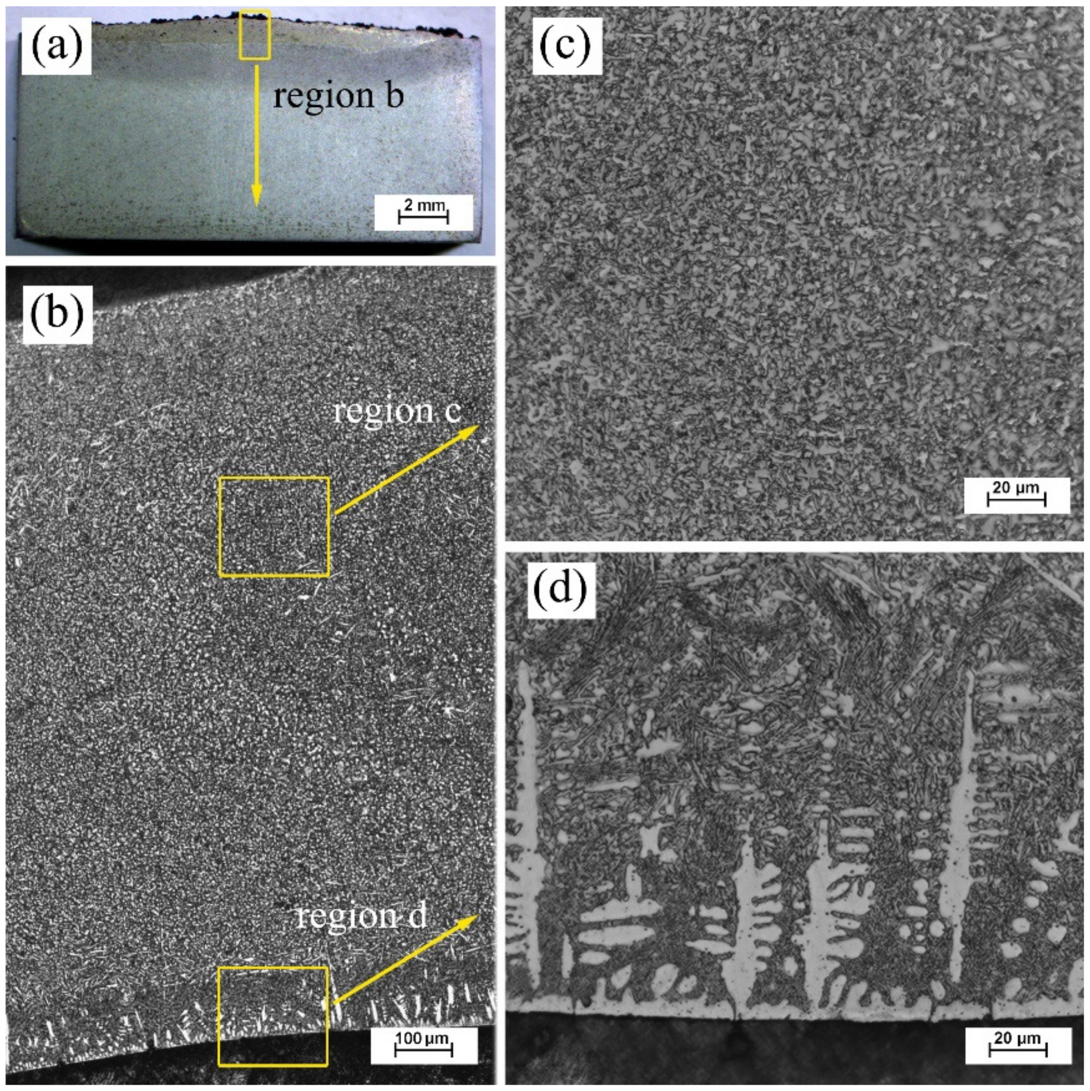
  • The microstructure analysis showed that the microstructure of the coating 1# with the least Ti and B4C addition was mainly composed of equiaxial grains. The content of in-situ precipitates distributed at the interdendritic space in coating 1#. As the adscititious Ti and B4C increased in coating 2# and 3#, the needle-like precipitates, block precipitates and lamellar eutectics were also significantly increased.
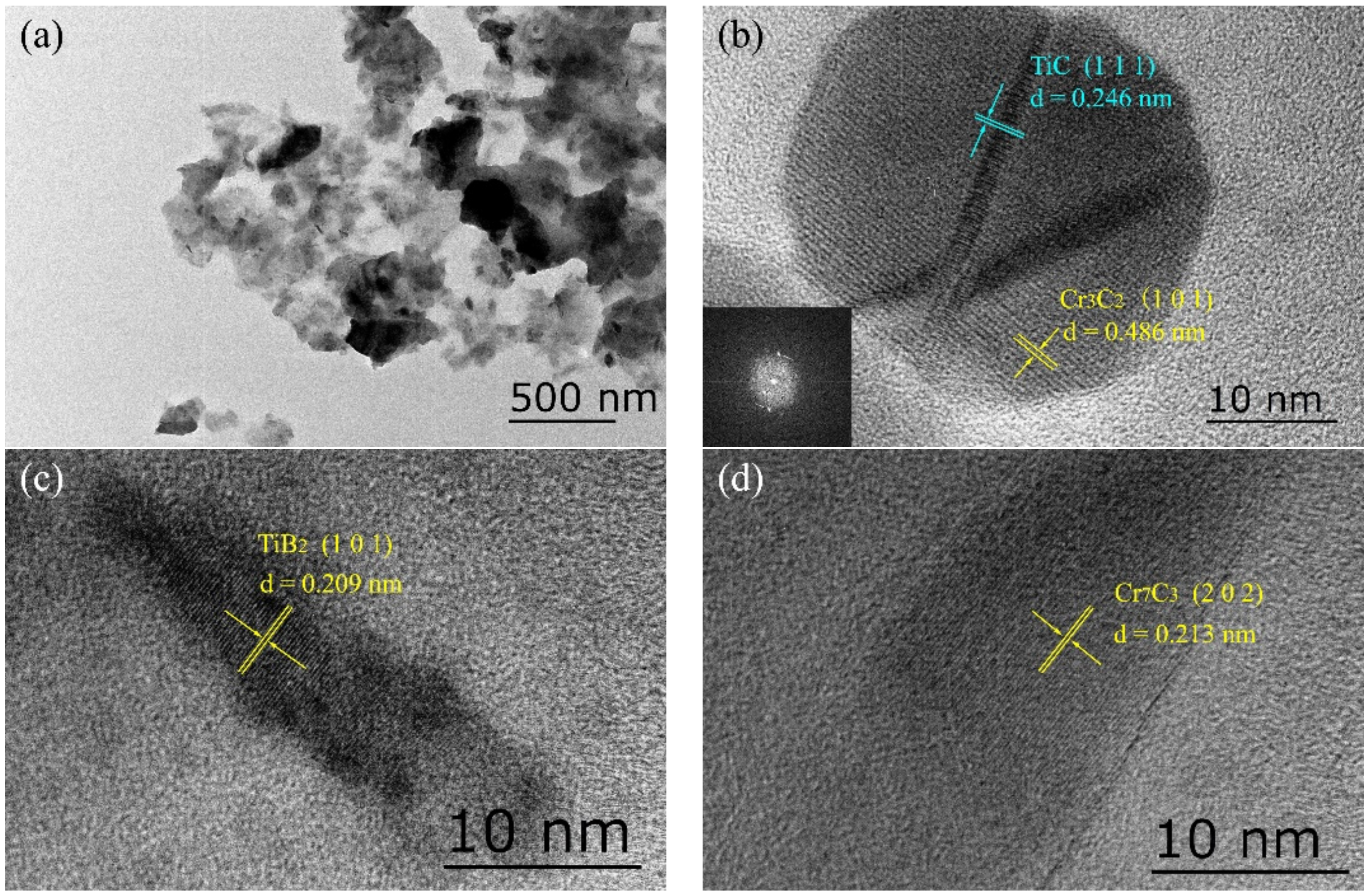
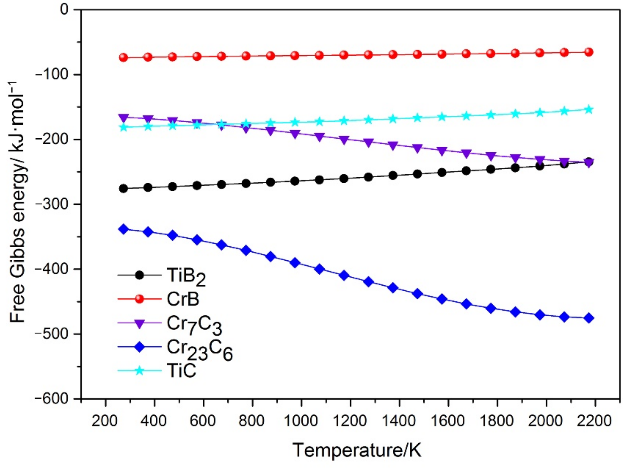
  • XRD patterns and TEM characterization confirmed that the multiple in-situ phases consist of Cr7C3, Cr23C6, TiC, CrB and TiB. It is believed that B4C was fully decomposed in the laser molten pool, which promotes the formation of various in-situ precipitated phases.
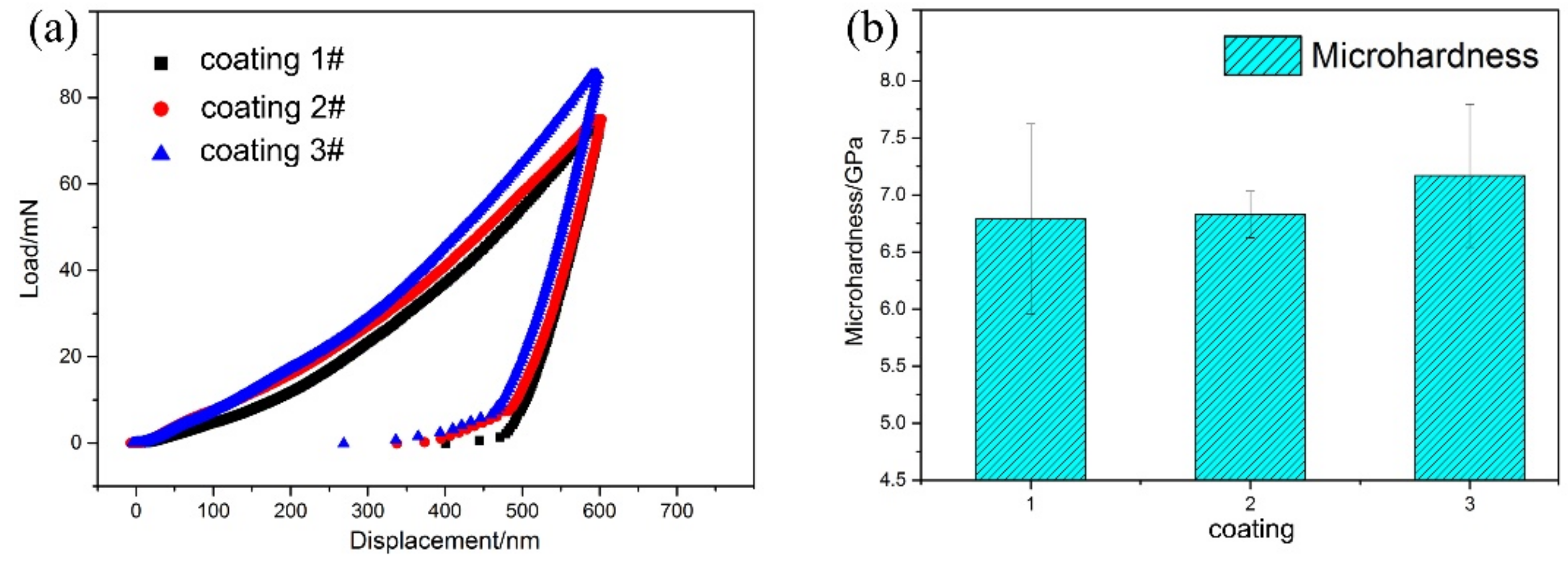
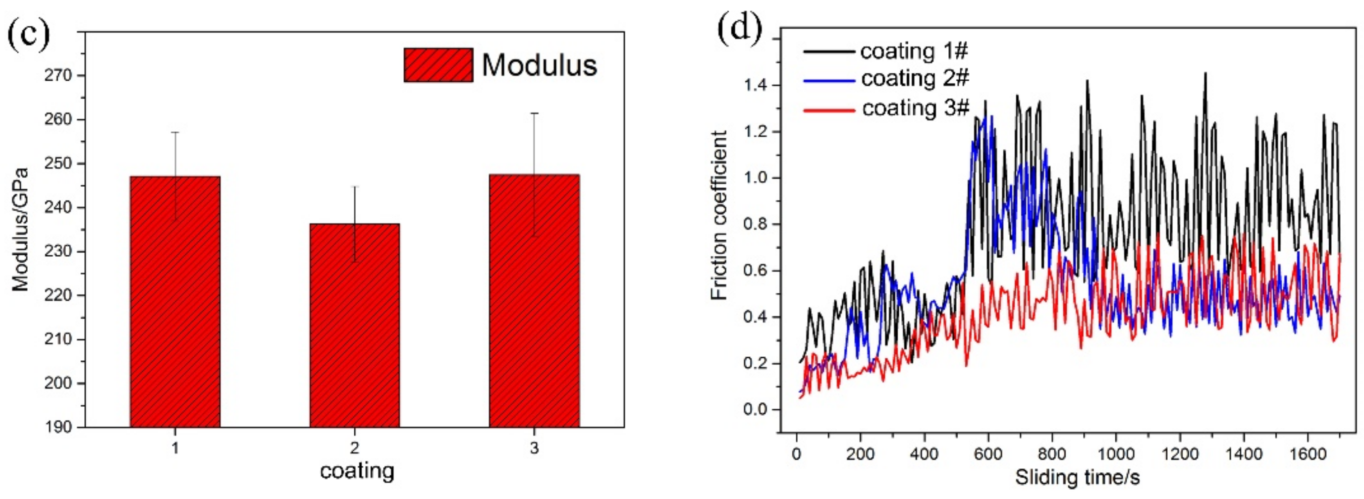
  • Mechanical properties of composite coatings were evaluated by nanoindentation tests. Results indicated the elastic modulus was approximately 240 GPa, which changed slightly in the different coatings. In the contrast, the microhardness increased to the maximum 7.18 GPa in the coating with 10 wt.% Ti and B4C addition. The average friction coefficient of composite coating was about 0.50.

Author Contributions

Writing-original draft preparation, Q.M.; Writing-review and editing, N.R.; Methodology, Z.D., S.H., J.C. and L.H.; Data collection, Q.M., Z.D., S.H. and J.C.; Data analysis, N.R., W.M. and L.H.; Funding acquisition, Q.M., W.M. and L.H. All authors have read and agreed to the published version of the manuscript.

Funding

This research was financially supported by the National Natural Science Foundation of China (52005007), Anhui Provincial Natural Science Foundation (1908085QE198) and Natural Science Fund of Anhui Province Education Office (KJ2018A0063, KJ2019A0069).

Institutional Review Board Statement

Not applicable.

Informed Consent Statement

Not applicable.

Data Availability Statement

The data presented in this study are available on request from the corresponding author.

Conflicts of Interest

The authors declare no known conflict of interest.

References

  1. Feldshtein, E.E.; Dyachkova, L.N. Wear minimization for highly loaded iron-based MMCs due to the formation of spongy-capillary texture on the friction surface. Wear 2020, 444–445, 203161. [Google Scholar] [CrossRef]
  2. Fu, S.; Yang, L.; Wang, P.; Wang, S.; Li, Z. Comparison of the microstructure evolution and wear resistance of Ti6Al4V composite coatings reinforced by hard pure or Ni-plated cubic boron nitride particles prepared with laser cladding on a Ti6Al4V substrate. Coatings 2020, 10, 702. [Google Scholar] [CrossRef]
  3. Ping, X.; Fu, H.; Sun, S.; Lin, J.; Guo, X.; Lei, Y. Microstructure and performance of Nb-bearing Ni60A-Cr3C2 Coatings Manufactured by Laser Cladding. Surf. Eng. 2020, 12, 1294–1306. [Google Scholar] [CrossRef]
  4. Zhao, Y.; Yu, T.; Sun, J.; Jiang, S. Microstructure and properties of laser cladded B4C/TiC/Ni-based composite coating. Int. J. Refract. Metals Hard Mater. 2020, 86, 105112. [Google Scholar] [CrossRef]
  5. Gou, Q.; Xiong, J.; Guo, Z.; Liu, J.; Yang, L.; Li, X. Influence of NbC additions on microstructure and wear resistance of Ti(C,N)-based cermets bonded by CoCrFeNi high-entropy alloy. Int. J. Refract. Metals Hard Mater. 2020, 94, 105375. [Google Scholar] [CrossRef]
  6. Venkatesh, L.N.; Babu, P.S.; Gundakaram, R.C.; Doherty, R.D.; Joshi, S.V.; Samajdar, I. Morphology-dependent hardness of Cr7C3-Ni-Rich alloy composite vs orientation independent hardness of Cr7C3 primary phase in a laser clad microstructure. Metall. Mater. Trans. A 2017, 48, 1534–1539. [Google Scholar] [CrossRef]
  7. Qunshuang, M.; Haozhe, C.; Hui, Z.; Wei, M.; Lei, H.; Huadong, L.; Yitao, W.; Xiaohui, Y. The alloying effects of Cr on in-situ phase evolution and wear resistance of nickel composite coatings fabricated by wide-band laser deposition. Surf. Coat. Technol. 2020, 397, 126019. [Google Scholar] [CrossRef]
  8. Xia, M.; Liu, A.; Lin, Y.; Li, N.; Ding, H.; Zhong, C. Densification behavior, microstructure evolution and fretting wear performance of in-situ hybrid strengthened Ti-based composite by laser powder-bed fusion. Vacuum 2019, 160, 146–153. [Google Scholar] [CrossRef]
  9. Zhang, M.; Li, M.; Chi, J.; Wang, S.; Ren, L.; Fang, M. Microstructure and tribology properties of in-situ MC(M:Ti, Nb) coatings prepared via PTA technology. Vacuum 2019, 160, 264–271. [Google Scholar] [CrossRef]
  10. Sun, S.; Fu, H.; Ping, X.; Guo, X.; Lin, J.; Lei, Y.; Wu, W.; Zhou, J. Effect of CeO2 addition on microstructure and mechanical properties of in-situ (Ti, Nb)C/Ni coating. Surf. Coat. Technol. 2019, 359, 300–313. [Google Scholar] [CrossRef]
  11. Gopinath, M.; Karmakar, D.P.; Nath, A.K. In-process detection of microstructural changes in laser cladding of in-situ Inconel 718/TiC metal matrix composite coating. J. Alloys Compd. 2018, 740, 545–558. [Google Scholar]
  12. Sun, S.; Fu, H.; Ping, X.; Lin, J.; Lei, Y.; Wu, W.; Zhou, J. Reinforcing behavior and microstructure evolution of NbC in laser cladded Ni45 coating. Appl. Surf. Sci. 2018, 455, 160–170. [Google Scholar] [CrossRef]
  13. Verdi, D.; Múnez, C.J.; Garrido, M.A.; Poza, P. Process parameter selection for Inconel 625-Cr3C2 laser cladded coatings. Int. J. Adv. Manuf. Technol. 2017, 92, 3033–3042. [Google Scholar] [CrossRef]
  14. Yang, H.; Gao, T.; Wu, Y.; Zhang, H.; Nie, J.; Liu, X. Microstructure and mechanical properties at both room and high temperature of in-situ TiC reinforced Al–4.5Cu matrix nanocomposite. J. Alloys Compd. 2018, 767, 606–616. [Google Scholar] [CrossRef]
  15. Cao, L.; Xia, Y.; Cui, H.; Li, Q.; Zhu, B.; Wang, Q. Microstructural characteristics of TiB2–TiC–NiAl composite coatings via plasma cladding process. Surf. Eng. 2019, 35, 997–1002. [Google Scholar] [CrossRef]
  16. Hu, Y.; Zhao, B.; Ning, F.; Wang, H.; Cong, W. In-situ ultrafine three-dimensional quasi-continuous network microstructural TiB reinforced titanium matrix composites fabrication using laser engineered net shaping. Mater. Lett. 2017, 195, 116–119. [Google Scholar] [CrossRef]
  17. Jażdżewska, M. Effects of CO2 and Nd:YAG laser remelting of the Ti6Al4V alloy on the surface quality and residual stresses. Adv. Mater. Sci. 2020, 20, 82–90. [Google Scholar] [CrossRef]
  18. Kik, T. Heat source models in numerical simulations of laser welding. Materials 2020, 13, 2653. [Google Scholar] [CrossRef]
  19. Pańcikiewicz, K.; świerczyńska, A.; Hućko, P.; Tumidajewicz, M. Laser dissimilar welding of AISI 430F and AISI 304 stainless steels. Materials 2020, 13, 4540. [Google Scholar] [CrossRef]
  20. Nepapushev, A.; Moskovskikh, D.; Vorotilo, K.; Rogachev, A. TiAl-based materials by in situ selective laser melting of Ti/Al reactive composites. Metals 2020, 10, 1505. [Google Scholar] [CrossRef]
  21. Tang, B.; Tan, Y.; Xu, T.; Sun, Z.; Li, X. Effects of TiB2 particles content on microstructure, mechanical properties and tribological properties of Ni-based composite coatings reinforced with TiB2 particles by laser cladding. Coatings 2020, 10, 813. [Google Scholar] [CrossRef]
  22. Bai, L.; Li, J.; Chen, J.; Song, R.; Shao, J.; Qu, C. Effect of the content of B4C on microstructural evolution and wear behaviors of the laser-clad coatings fabricated on Ti6Al4V. Opt. Laser Technol. 2016, 76, 33–45. [Google Scholar] [CrossRef]
  23. Yilbas, B.S.; Patel, F.; Karatas, C. Laser controlled melting of HSLA steel surface with presence of B4C particles. Appl. Surf. Sci. 2013, 282, 601–606. [Google Scholar] [CrossRef]
  24. Ma, Q.; Li, Y.; Yin, X.; Meng, W. Effects of laser fluence on microstructure and bonding characteristics of wideband laser-deposited nickel composite coatings. J. Mater. Eng. Perform. 2019, 28, 2661–2671. [Google Scholar] [CrossRef]
  25. Farahmand, P.; Kovacevic, R. An experimental–numerical investigation of heat distribution and stress field in single- and multi-track laser cladding by a high-power direct diode laser. Opt. Laser Technol. 2014, 63, 154–168. [Google Scholar] [CrossRef]
  26. Lei, Y.; Sun, R.; Tang, Y.; Niu, W. Numerical simulation of temperature distribution and TiC growth kinetics for high power laser clad TiC/NiCrBSiC composite coatings. Opt. Laser Technol. 2012, 44, 1141–1147. [Google Scholar] [CrossRef]
  27. Bedenko, D.V.; Kovalev, O.B.; Smurov, I.; Zaitsev, A.V. Numerical simulation of transport phenomena, formation the bead and thermal behavior in application to industrial DMD technology. Int. J. Heat Mass Transf. 2016, 95, 902–912. [Google Scholar] [CrossRef]
  28. Oliver, W.C.; Pharr, G.M. An improved technique for determining hardness and elastic modulus using load and displacement sensing indentation experiments. J. Mater. Res. 1992, 7, 1564–1583. [Google Scholar] [CrossRef]
  29. Steffen, G.; Lutz, K.; Markus, R.; Ines, S. Characterization of in-situ TiB/TiC particle-reinforced Ti–5Al–5Mo–5V–3Cr matrix composites synthesized by solid-state reaction with B4C and graphite through SPS. Metals 2018, 8, 377. [Google Scholar]
  30. Yao, J.; Yang, L.; Li, B.; Li, Z. Beneficial effects of laser irradiation on the deposition process of diamond/Ni60 composite coating with cold spray. Appl. Surf. Sci. 2015, 330, 300–308. [Google Scholar] [CrossRef]
  31. Zheng, C.; Liu, Z.; Chen, S.; Liu, C. Corrosion behavior of a Ni–Cr–Mo alloy coating fabricated by laser cladding in a simulated sulfuric acid dew point corrosion environment. Coatings 2020, 10, 849. [Google Scholar] [CrossRef]
  32. Wang, X.; Zhou, S.; Dai, X.; Lei, J.; Guo, J.; Gu, Z.; Wang, T. Evaluation and mechanisms on heat damage of WC particles in Ni60/WC composite coatings by laser induction hybrid cladding. Int. J. Refract. Metals Hard Mater. 2017, 64, 234–241. [Google Scholar] [CrossRef]
  33. Zhou, S.; Lei, J.; Dai, X.; Guo, J.; Gu, Z.; Pan, H. A comparative study of the structure and wear resistance of NiCrBSi/50 wt.% WC composite coatings by laser cladding and laser induction hybrid cladding. Int. J. Refract. Metals Hard Mater. 2016, 60, 17–27. [Google Scholar] [CrossRef]
  34. Bartkowski, D.; Bartkowska, A. Wear resistance in the soil of Stellite-6/WC coatings produced using laser cladding method. Int. J. Refract. Metals Hard Mater. 2017, 64, 20–26. [Google Scholar] [CrossRef]
  35. Li, W.; Yang, Y.; Liu, J.; Zhou, Y.; Li, M.; Wen, S.; Wei, Q.; Yan, C.; Shi, Y. Enhanced nanohardness and new insights into texture evolution and phase transformation of TiAl/TiB2 in-situ metal matrix composites prepared via selective laser melting. Acta Mater. 2017, 136, 90–104. [Google Scholar] [CrossRef]
  36. Zhang, Y.; Yu, X.; Jiang, W.; Tu, S.; Zhang, X. Elastic modulus and hardness characterization for microregion of Inconel 625/BNi-2 vacuum brazed joint by high temperature nanoindentation. Vacuum 2020, 181, 109582. [Google Scholar] [CrossRef]
  37. Gao, W.; Chang, C.; Li, G.; Xue, Y.; Wang, J.; Zhang, Z.; Lin, X. Study on the laser cladding of FeCrNi coating. Optik 2019, 178, 950–957. [Google Scholar] [CrossRef]
  38. Wang, K.; Du, D.; Liu, G.; Chang, B.; Ju, J.; Sun, S.; Fu, H. Microstructure and property of laser clad Fe-based composite layer containing Nb and B4C powders. J. Alloys Compd. 2019, 802, 373–384. [Google Scholar] [CrossRef]
  39. Liang, J.; Yin, X.; Lin, Z.; Chen, S.; Liu, C.; Wang, C. Microstructure and wear behaviors of laser cladding in-situ synthetic (TiBx + TiC)/(Ti2Ni + TiNi) gradient composite coatings. Vacuum 2020, 176, 109305. [Google Scholar] [CrossRef]
  40. Qunshuang, M.; Yajiang, L.; Juan, W. Effects of Ti addition on microstructure homogenization and wear resistance of wide-band laser clad Ni60/WC composite coatings. Int. J. Refract. Metals Hard Mater. 2017, 64, 225–233. [Google Scholar] [CrossRef]
  41. Li, J.; Zhang, X.; Wang, H.; Li, M. Microstructure and mechanical properties of Ni-based composite coatings reinforced by in situ synthesized TiB2 + TiC by laser cladding. Int. J. Refract. Metals Hard Mater. 2013, 20, 57–64. [Google Scholar] [CrossRef]
  42. Han, C.; Babicheva, R.; Chua, J.D.Q.; Ramamurty, U.; Tor, S.B.; Sun, C.; Zhou, K. Microstructure and mechanical properties of (TiB + TiC)/Ti composites fabricated in situ via selective laser melting of Ti and B4C powders. Addict. Manuf. 2020, 36, 101466. [Google Scholar] [CrossRef]
  43. Li, Q.; Zhang, H.; Li, D.; Chen, Z.; Wang, F.; Wu, M. Comparative study of the microstructures and mechanical properties of laser metal deposited and vacuum arc melted refractory NbMoTa medium-entropy alloy. Int. J. Refract. Metals Hard Mater. 2020, 88, 105195. [Google Scholar] [CrossRef]
  44. Singh, J.; Thakur, L.; Angra, S. A study of tribological behaviour and optimization of WC–10Co–4Cr cladding. Surf. Eng. 2020, 1–10. [Google Scholar] [CrossRef]
  45. Yanan, L.; Ronglu, S.; Wei, N.; Tiangang, Z.; Yiwen, L. Effects of CeO2 on microstructure and properties of TiC/Ti2Ni reinforced Ti-based laser cladding composite coatings. Opt. Laser. Eng. 2019, 120, 84–94. [Google Scholar] [CrossRef]
  46. Wang, M.; Lu, W.; Qin, J.; Ma, F.; Lu, J.; Zhang, D. Effect of volume fraction of reinforcement on room temperature tensile property of in situ (TiB + TiC)/Ti matrix composites. Mater. Des. 2006, 27, 494–498. [Google Scholar] [CrossRef]
  47. Wang, S.; Zhang, S.; Zhang, C.; Wu, C.; Chen, J.; Shahzad, M.B. Effect of Cr3C2 content on 316L stainless steel fabricated by laser melting deposition. Vacuum 2018, 147, 92–98. [Google Scholar] [CrossRef]
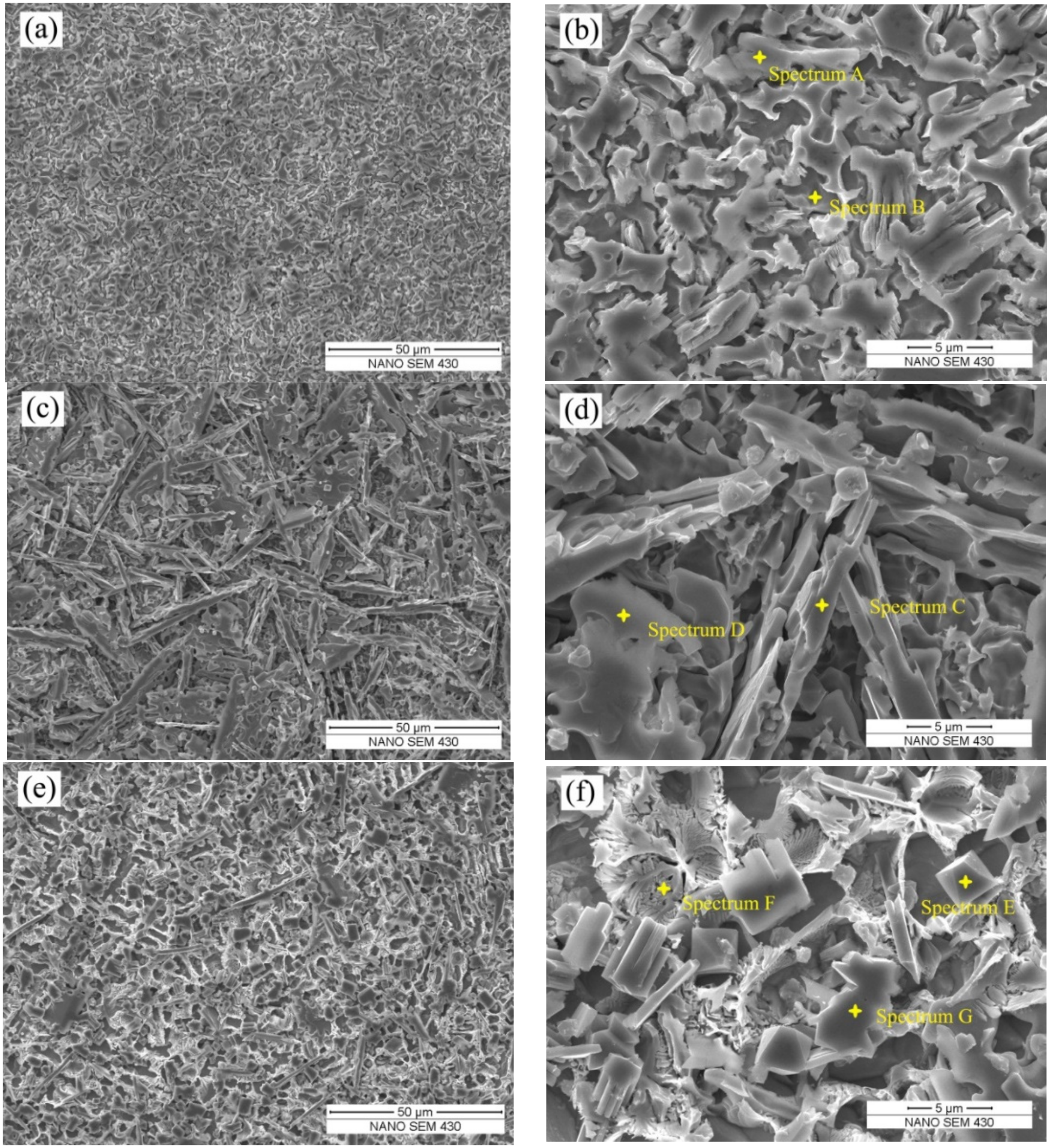
Figure 1. Macro observation of wide-band laser deposited composite coatings: (a) surface morphology and (b) cross-section.
Coatings 11 00036 g001
Figure 2. Phase identification by XRD patterns of different composite coatings.
Coatings 11 00036 g002
Figure 3. Microstructure of composite coating 1#: (a) cross-section (b) magnified region (c) magnified middle zone and (d) magnified interface zone.
Coatings 11 00036 g003
Figure 4. Magnified microstructure at the interface zone of composite coating 1#: (a) dendrites and (b) eutectics: (a-1) test point; (a-2) chemical composition; (b-1) test point; (b-2) chemical composition.
Coatings 11 00036 g004
Figure 5. Field emission SEM images of the in-situ synthesized phases in coatings with different Ti and B4C content: (a,b) 2.0 wt.%, (c,d) 5.0 wt.% and (e,f) 10 wt.%.
Coatings 11 00036 g005
Figure 6. Micrographs of various in-situ phases observed by HR-TEM: (a) bright field electron image (b) high resolution lattice of Cr3C2 and TiC along with the inset showing the FFT (fast Fourier transform) patterns (c) High resolution lattice image of TiB2 (d) High resolution lattice image of Cr7C3 (e) diffraction spot patterns of CrB and (f) diffraction spot patterns of Cr23C6.
Coatings 11 00036 g006aCoatings 11 00036 g006b
Figure 7. Results of nanoindentation and friction wear tests on different composite coatings: (a) typical load-displacement curves (b) microhardness (c) elastic modulus and (d) friction coefficient.
Coatings 11 00036 g007aCoatings 11 00036 g007b
Figure 8. Change of Gibbs free energy as a function of temperature for reactions Equations (4)–(8).
Coatings 11 00036 g008
Table 1. Chemical composition of marked location in Figure 5 (wt.%).
SamplePointCNiCrFeTiProbable Phase
1#A1.2624.0032.8537.89Cr7C3 + γ-Ni
B66.506.2027.30γ-Ni
2#C4.157.3946.4835.736.24Cr7C3 + TiC
D1.3757.307.6430.822.88γ-Ni
3#E1.9279.088.5510.45CrB
F0.999.5450.8137.161.50Cr23C6 + γ-Ni
G1.3469.023.5018.977.18γ-Ni
Publisher’s Note: MDPI stays neutral with regard to jurisdictional claims in published maps and institutional affiliations.

