Article

Microstructure and Properties of Fe-Based Alloy Coating on Gray Cast Iron Fabricated Using Induction Cladding

1
Marine Engineering College, Dalian Maritime University, Dalian 116026, China
2
Department of Strategy Implementation, Dalian Special Equipment Inspecting Institute, Dalian 116013, China
*
Author to whom correspondence should be addressed.
Coatings 2020, 10(9), 801; https://doi.org/10.3390/coatings10090801
Submission received: 23 July 2020 / Revised: 8 August 2020 / Accepted: 14 August 2020 / Published: 19 August 2020
(This article belongs to the Special Issue Corrosion Science and Surface Engineering)

Abstract

:
Gray cast iron is widely used for the cylinder bore of marine diesel engine. With the aim to improve the properties of the cylinder liner and maintain the matching ability with piston ring under the harsh working condition, the Fe-based alloy coating is fabricated on the gray cast iron using induction cladding. Owing to the high carbon content in both coating and substrate materials, it is extremely difficult to control the coating process and the coating quality. The additive of welding flux and prolonged heating time is proposed to prepare good quality coating. The coating forming mechanism is investigated, and the electrochemical corrosion and tribological properties of the coating are examined. The results show that the Fe-based coating possess better corrosive and tribological performance than gray cast iron, and it is seemed to be a potential candidate for improving the performance of the cylinder liner.

1. Introduction

With the development of marine diesel engine, the critical working parameters of engine are dramatically intensified, such as higher power, higher combustion efficiency, lower fuel consumption, lower emission, and longer service life. Cylinder liner is a key component influencing the durability of an engine, and accordingly, its corrosion resistance and wear performance need to be further improved. Surface coating technique is not only a highly effective approach to improve the surface performance, combining with choosing various coating materials and designing flexible coating structures, but also provides a potential option to reduce fuel consumption and emissions [1]. Widely used surface coating techniques include electroplating [2], physical vapor deposition (PVD) [3], thermal spraying [4], and cladding, in which laser cladding and induction cladding have the great potential to fabricate coating with large area and controllable thickness and metallurgically bonding with the substrate. However, due to the limited laser spot size, there is multitrack and multilayer inside the large size coating, which in turn leads to the overlap zone remelted and reheated, and consequently initiating cracks and defects in the coating [5]. Induction cladding is an emerging and potentially applicable candidate, which possesses the advantages of induction heating and surface coating [6]. The fundamental principle of induction cladding is using skin effect and Joule heating induced by alternating current to coat the alloy powder or its composite on the substrate [7]. Common materials for induction cladding involve Ni-based, Fe-based, and Co-based alloy powders and its composite with good wear resistance and high temperature properties [8], in which Fe-based powder has relatively lower price and better wear resistance.
Cast iron with outstanding wear resistance is a common material for cylinder liner of marine diesel engine [9]. In order to improve the operating performance of cylinder liner of highly intensified diesel engine, depositing a coating is a practical solution. However, due to the high carbon content of cast iron, a hard and brittle layer between the coating and substrate is easily generated, which in turn initiates microcrack and defect at the bonding interface, therefore, weakening the bonding strength [10,11]. In our previous work [12,13], the Ni-based alloy coating has been coated onto the gray cast iron using the multistep induction cladding technique and the corrosion and wear performance have been examined. The results reveal that there is no microcrack and gas pore in the bonding zone between coating and substrate, and the corrosion and wear resistance of coating is superior to the substrate.
With aim to improve the performance of cylinder liner under the harsh operating condition, meanwhile to remain the matching ability between piston ring and cylinder jacket inner wall, Fe-based alloy coating is one of the most suitable alternatives with the similar properties to the substrate. However, due to the high carbon content in both coating and matrix materials, it is extremely difficult to control the cladding process and the coating quality. Flux agent and heat treatment can effectively improve the quality of cladding coating [14,15]. In this paper, Fe-based alloy coating was prepared by induction cladding on the gray cast iron substrate, and the additive of welding flux and prolonged heating time were employed to fabricate high-quality Fe-based coating. The mechanism of the coating formation was investigated, and subsequently, the characterization and properties of the coating were examined.

2. Experiment Procedures

2.1. Materials and Induction Cladding Process

Gray cast iron HT 300 is a commonly used material for the cylinder liner of diesel engine, therefore, it is chosen as the substrate. The chemical compositions of HT 300 and a commercial Fe-based alloy powder (Shenyang Rare Metals Research Institute) are listed in Table 1. In an attempt to facilitate the melting process of Fe-based alloy powder, a welding flux was utilized in this study, and the chemical composition (mass%) was KF (40–44%), B2O3 (33–37%), and KBF4 (21–25%). The dimensions of the substrate were Φ 20 mm × 100 mm.
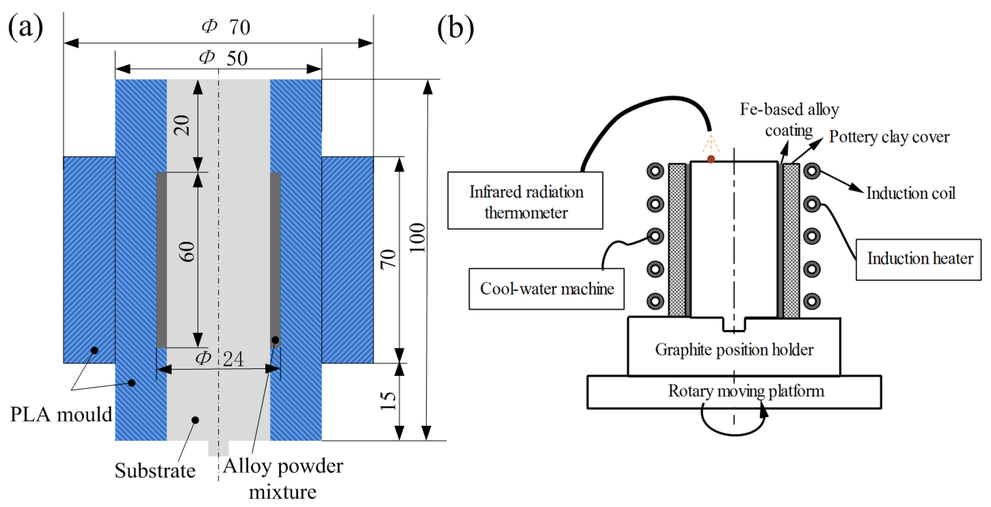
The sample preparation is illustrated in Figure 1. The HT 300 substrate was pretreated by sandblasting followed by ultrasonic cleaning in order to roughen, activate, and clean the surface of the substrate, so as to improve the bonding strength between the substrate and the coating. In order to investigate the effect of the welding flux on the coating formation, two types of precoating materials were prepared, the uniform mixture of the Fe-based alloy powder and a saturated sodium silicate solution (sample Fe-1) and the mixture of welding flux and Fe-based alloy powder with mass ratio of 1:10, and then, it was uniformly mixed in a saturated sodium silicate solution (samples Fe-2 and Fe-3). A polylactic acid (PLA) mold was employed to precoat the alloy layer onto the substrate with thickness of 2 mm, as shown in Figure 2a. After that, the sample was dried at the room temperate for 30 min and, subsequently, was heated at 150 °C for 3 h. In order to prevent the molten alloy powder from being oxidized during the induction heating process and reduce the cooling rate of the heated coating, a pottery clay cover was placed outside the precoated alloy layer. The prepared sample was fixed on the graphite position holder, which was placed above the rotary moving device. The schematic diagram of induction cladding device is shown in Figure 2b. It consisted of the induction heater with the frequency ranging from 40 to 100 kHz, cool-water machine, rotary moving platform, and infrared radiation thermometer.
Based on numerous experiments, the induction cladding parameters for Fe-based alloy coating are listed in Table 2. The heating processes of sample Fe-1 and Fe-2 included preheating and heating stages, while sample Fe-3 had an extra heat preservation of 30 s at low current of 10 A.

2.2. Characterization of the Coating

The sample treated by induction cladding was cut along the radial direction using the electrical discharge machine (EDM). The observed surface was polished with emery paper, and then with the diamond powder, finally was eroded with alcohol solution containing 4% of nitric acid (volume fraction). An optical microscope (OM, GX51, OLYMPUS, Tokyo, Japan) and a Supra 55 Sapphire scanning electron microscope (SEM) with an energy dispersive spectrometer (EDS) were employed to observe the microstructure and element distribution at the cross-section of the coating. The phase composition of the coating was examined by an X-ray diffractometer (XRD, PANalytical Empyrean, Almelo, The Netherlands). The hardness of the coating was measured using a Vickers microhardness tester (LW-HV 1000, Beijing Leweiwulian Science and Technology Co., Ltd., Beijing, China) with a load of 200 g, a load holding time of 20 s, and a distance interval between testing points of 50 μm.

2.3. Electrochemical Corrosion Test

To evaluate the electrochemical behavior of the coating and substrate, the polarization curve and AC impedance spectroscopy were measured by an electrochemical workstation CHI604E (CH Instruments, Inc., New York, NY, USA). The tests were conducted in 3.5% NaCl solution at room temperature, and the three-electrode system was applied, in which the tested sample served as the working electrode, Pt plate was chosen for the counter electrode, and SCE was used as the reference electrode. The exposed testing area of the sample is 10 × 10 mm2, and the other part of the sample was sealed by phenolic resin. Before starting the test, the sample was immersed in the electrolyte for 30 min to stabilize the open circuit voltage. The potentiodynamic scanning rate is 0.1 V/s, and testing range is −2.5~2.0 V. In AC impedance spectroscopy test, the measurement frequency ranged from 10−2 to 105 Hz, and the interference voltage was 10 mV. The microstructure and chemical composition of the corroded samples were analyzed by SEM and EDS.

2.4. Wear Test

The tribo-property of the coating and substrate were tested on a self-designed reciprocating sliding tribo-tester (Figure 3) under dry sliding condition at room temperature. The material of the counterpart was gray cast iron coated with chromium layer (the thickness of the coating was 100 μm, and the microhardness was 800–900 HV0.2), commonly used for the piston ring. The tribological pair was fixed on the jig reciprocating at 0.7 m/s controlled by a servo motor, with the dimension of 45 × 95 × 10 mm3. The Fe-based alloy coating specimen had a dimension of 10 × 10 × 15 mm3, held by a stationary clamp. The coating specimen with a contact surface area of 10 × 10 mm2 was vertically pressed on the tribological pair at a load of 100 N. Based on our previous experimental results, we found that for the Fe-based alloy coating and substrate, when the sliding distance was beyond 1500 m, the friction coefficient and wear loss exhibited a stable tendency. Therefore, the sliding distance is set at 2500 m. The friction coefficient and wear loss are measured at the sliding distance of 625, 1250, 1875 and 2500 m. In an attempt to compare the tribological performance between the Fe-based alloy coating and gray cast iron substrate, the substrate sample with the same dimension as the coating sample was tested under the above tribological experimental condition. The coefficient of friction and sliding time were recorded automatically by an acquisition system. The wear loss was measured by an electronic balance with an accuracy of 0.1 mg. Before and after each test, all the test samples were cleaned by alcohol to remove the surface impurities for the wear loss measurement and surface observation. SEM and EDS were employed to analyze the wear mechanism.

3. Results and Discussion

3.1. Forming Mechanism of Fe-Based Coating

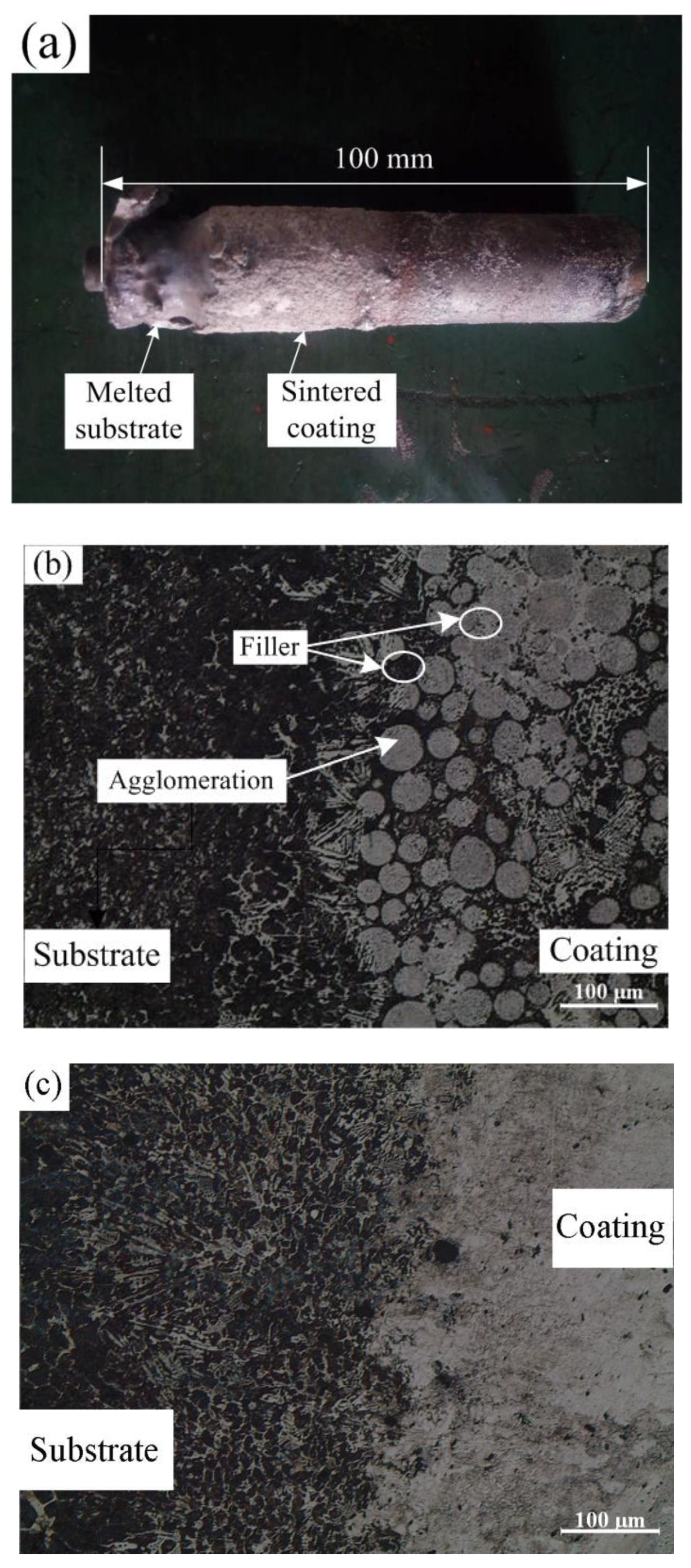
Figure 4a shows the photograph of sample Fe-1 without adding the welding flux. Owing to the Fe-based alloy powder easily being oxidized and having high carbon content, it is extremely difficult to directly fabricate the Fe-based alloy coating on the gray cast iron substrate. In our numerous previous experiments, Fe-based alloy powder is partly melted or over melted. The coating of sample Fe-2 contains the welding flux, but is heated for a shorter time period, as shown in Figure 4b. It can be observed that the coating metallurgically bonds with the substrate, but there is some amount of unmelted alloy powder and alloy agglomeration in the bottom of the coating. Some black and white substance fills in the agglomeration gap. The coating of sample Fe-3 with the welding flux is processed for an extra prolonged heating time, as shown in Figure 4c. The alloy powders melt completely. There are no cracks and very few pores in the vicinity of the bounding interface between the coating and substrate. However, due to the prolonged heating time, the phase transformation occurs in the substrate next to the coating.
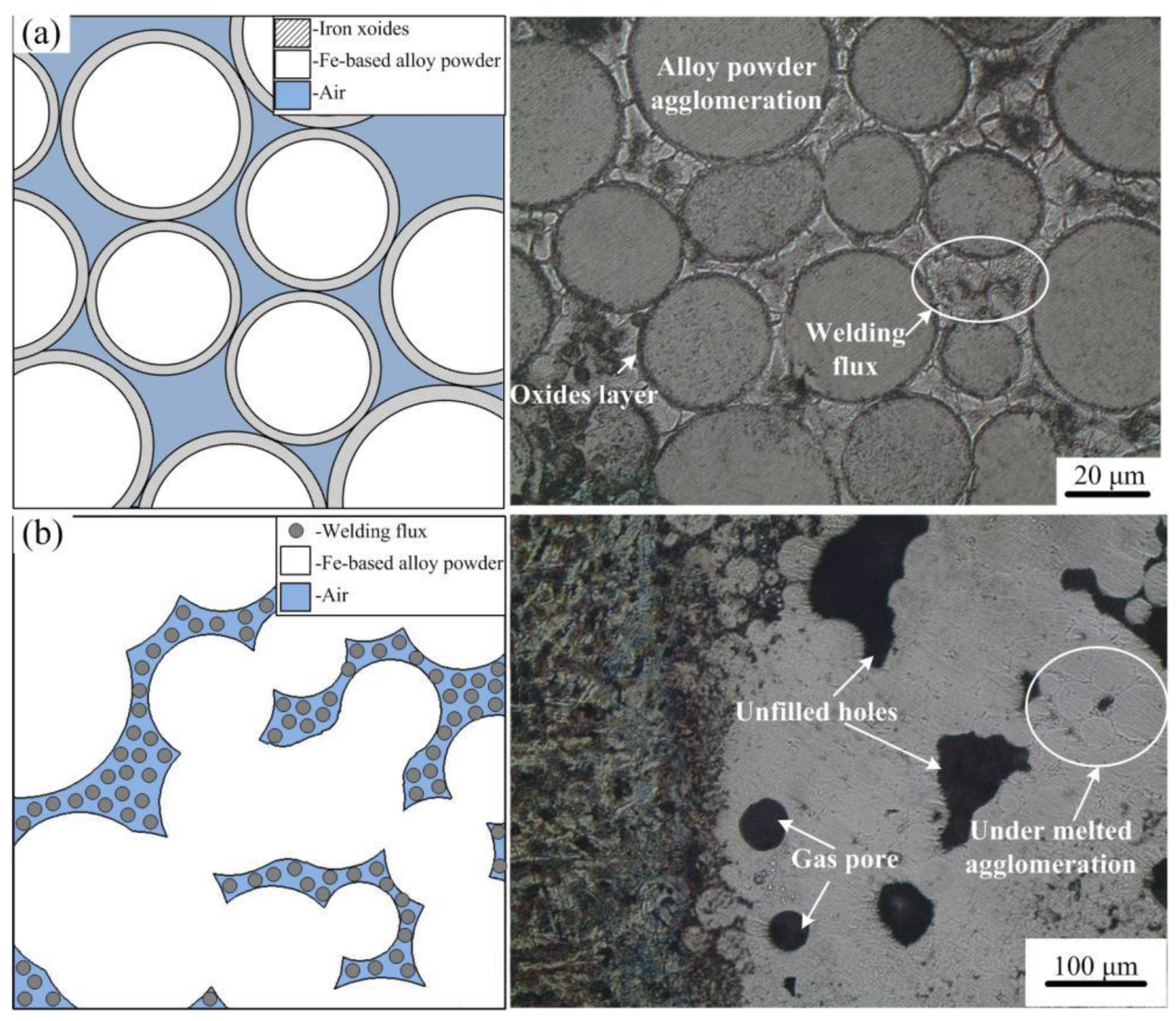
The mechanism of the welding flux and prolonged heating time improving the quality of the coating is illustrated in Figure 5. During the preheating phase, the heated Fe powder is easily oxidized by the air remained in the precoated alloy layer. Consequently, the oxide film is formed outside the Fe powder, which has higher melting point than that of the Fe-based alloy powder. As a result, the melting process is very difficult to be conducting. Moreover, the gap between alloy powders decreases the heat conductivity, which completely hinders the melting of alloy powder, as showed in Figure 5a. When the welding flux is uniformly mixed with the alloy powder, during the heating process, KF and KBF4 in the welding flux can remove the oxides layers outside the Fe powder, while B2O3 can chemically react with the oxides layers and, in turn, produce the borides, which can fill in the alloy powder gap and promote the heat conduction, as shown in Figure 5b. During the induction cladding, some white smoke is generated from the sample surface, which is the volatile borides and fluorides. Therefore, it can be inferred that the welding flux can decrease the sintering temperature of the alloy powder so as to promote the melting process. Because the deoxidization process of the welding flux conducts slowly, if the heating time is not longer enough, the alloy powder can still not melt completely and some holes and gas pores are formed in the coating. In addition, the melting alloy powder does not have strong flowability, resulting in the voids generated by the melted alloy powder that cannot be filled immediately. It can be inferred that the prolonged heating time can increase the extra heat input so that the alloy powder can be melting completely and the voids and gas pores can be decreased or eliminated.
From above results, it is found that the welding flux and prolonged heating time can noticeably improve the quality of Fe-based alloy coating. The following studies are all carried out focusing on sample Fe-3.

3.2. Microstructure and Composition of the Coating

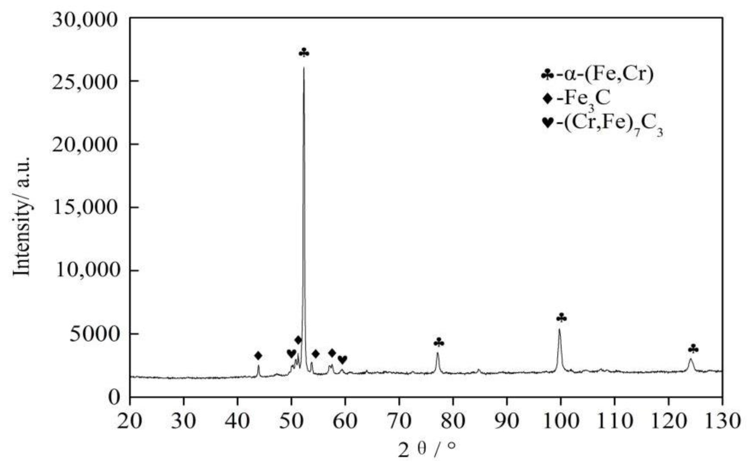
Figure 6 shows the phase composition of the coating (sample Fe-3). Referring to the chemical composition of Fe-based alloy powder, it can be inferred that the coatings surface primarily consists of α-(Fe, Cr), Fe3C, and (Cr, Fe)7C3.
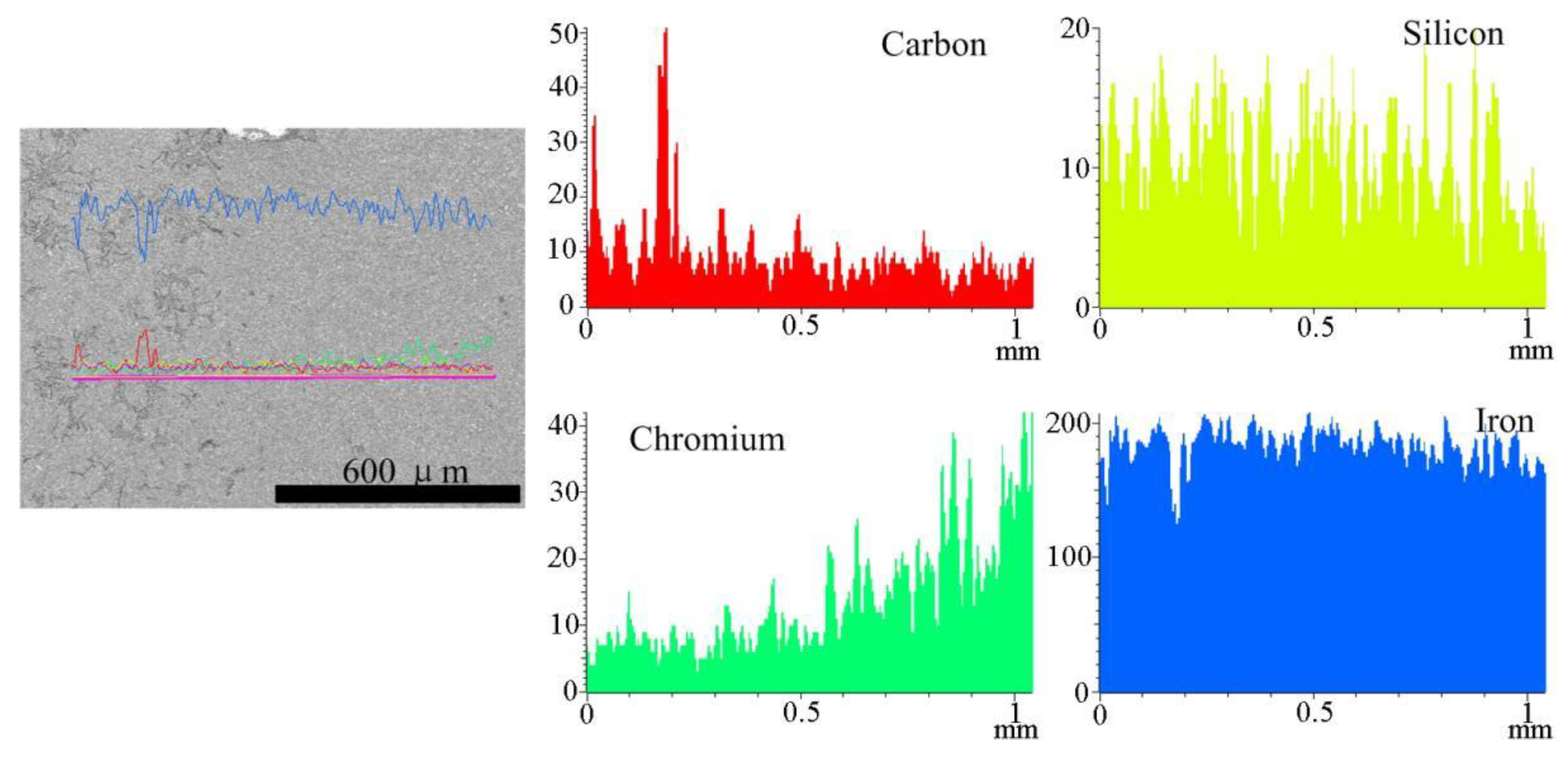
Line scanning results at the cross-section of the coating is shown in Figure 7. It can be observed that from the substrate to the coating the content of element Cr gradually increased, while the content of Fe, Si and C in the coating is slightly lower than that in the substrate. It can be concluded that the coating metallurgically bonds with the substrate, which possesses the similar interface zone with the coatings fabricated using arc welding [16] and laser cladding [17].
Figure 8 shows SEM images at the cross-section of the coating. It can be observed in Figure 8a that the substrate has typically gray cast iron microstructure, presenting the fine graphite scattering in the matrix of ferrite and pearlite, whereas in the coating, amount of dark gray block structure distributes in the light gray matrix and some of carbide and graphite spreads in it, which is similar to the microstructure in the interface zone of laser cladding coating [18]. Some amount of carbide and graphite is observed in the bonding zone, and coating is transferred from the substrate, which is not completely dissolved during the cladding process [19]. Figure 8b shows the microstructure inside the coating. According to the XRD result of the coating, it can be presumed that the network-like block structure is (Cr, Fe)7C3, the black particle is Fe3C, and the light gray region is α-(Cr, Fe).

3.3. Microhardness

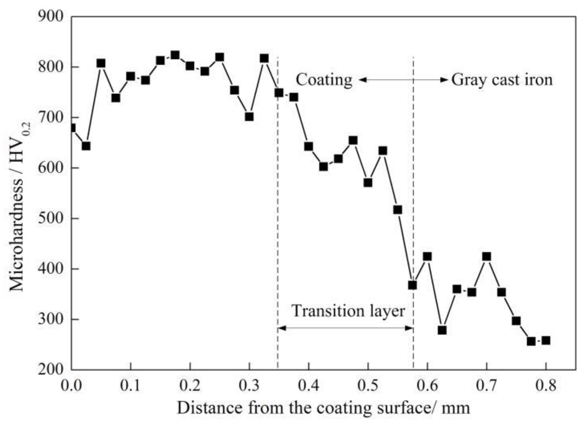
The hardness profile at the cross-section of the sample Fe-3 is shown in Figure 9. The hardness curve can be divided into three sections, including the coating, the elements interdiffusion zone, and the substrate. The average of the coating hardness is 765 HV0.2, which is four times higher than that of the gray cast iron substrate (150 HV0.2). The hardness in the coating slightly fluctuates, because the hard phases Fe3C and (Cr,Fe)7C3 unevenly distribute in the solid solution matrix α-(Fe,Cr). The hardness between the coating and substrate presents a gradient variation, and from the coating to the substrate the hardness gradually goes downwards because the bottom of the coating tolerates high temperature for long time and small amounts of element Fe in the substrate transfers into the coating, which is in line with the cross-sectional line scanning results of the coating in Figure 7.
The hardness of the substrate next to the coating (383.2 HV0.2) is higher than that in middle section. It is ascribed to that the highest eddy current occurs at the boundary between the coating and substrate, which, in turn, generates the highest temperature at the bonding interface, leading to the elements interdiffusion at the interface zone [20].

3.4. Electrochemical Corrosion Behavior in 3.5% NaCl

The potentiodynamic polarization curves of Fe-based coating and substrate are shown in Figure 10. The typical activation–passivation feature is presented in the Fe-based coating curve, which can be divided into activation region, passivation region, and transpassive region. In activation region, the electric potential varies from −1.1 to −0.8 V and the current density dramatically increases with the potential increase. In passivation region, due to the formation of the passive film, the passivation current density remains stable as the potential increases (−0.8~0.2). Compared with the potentiodynamic polarization curves of HT 300, the passivation region of Fe-based coating with a plateau is much longer, meanwhile the passivation current density of the coating is obviously lower. The plateaus are supposed to be caused by the generation of corrosion products on the coating [21]. Therefore, it is indicated that the coating has better corrosion resistance than the substrate in 3.5% NaCl solution.
The fitting parameters of potentiodynamic polarization curves of Fe-based coating and substrate are listed in Table 3. The self-corrosion potential of coating is more close to negative than that of the substrate, indicating that the coating is more likely to be corroded. However, the self-corrosion current density and corrosion rate of the coating is about two times lower than that of the substrate, implying that the corrosion resistance of the coating is superior to that of the substrate in 3.5% NaCl solution.
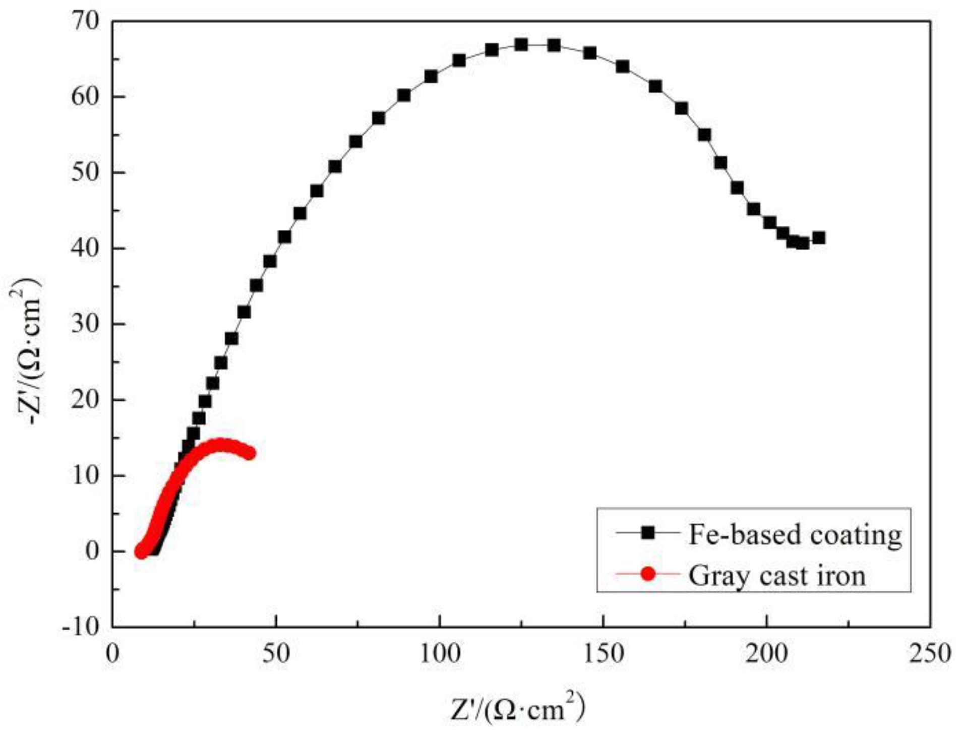
Nyquist plots of Fe-based coating and HT 300 in 3.5% NaCl solution are displayed in Figure 11. The Nyquist diagram of coating is composed of a capacitance arc in high-frequency zone and a small arc in low-frequency zone. In contrast, regrading to the gray cast iron, there is only one capacitance arc in high-frequency zone. When the electron transfers from the sample surface, a capacitance arc is in high-frequency zone, whereas the absorption and diffusion of the corrosion products can result in an arc or a line in the low-frequency zone. In high-frequency zone, the coating has a similar corrosion process to the substrate. The reaction products of the iron atom on the sample surface with the oxygen atom in the NaCl solution are the iron oxides, which attach to the sample surface, decreasing the corrosion rate. Moreover, chromium in the coating, which chemically bounds more easily with oxygen and, consequently, generates the dense chromium oxide film to further hamper the corrosion process, is much active than iron. From the morphology at the cross-sectional area of the coating, the pores are not connected inside the coating, and it means, no direct corrosion medium passages from the coating-free surface to substrate. Therefore, the impedance spectra of the coating and substrate can be fitted by the same equivalent circuit, as shown in Figure 12, and the detailed parameters of the equivalent circuit are listed in Table 4. It can be seen that the resistance in the coating surface and interface (Rt and Ra) is large than that of the substrate, therefore the coating possesses the better corrosion resistance than the substrate in 3.5% NaCl solution, which agrees with the results of potentiodynamic polarization analysis.
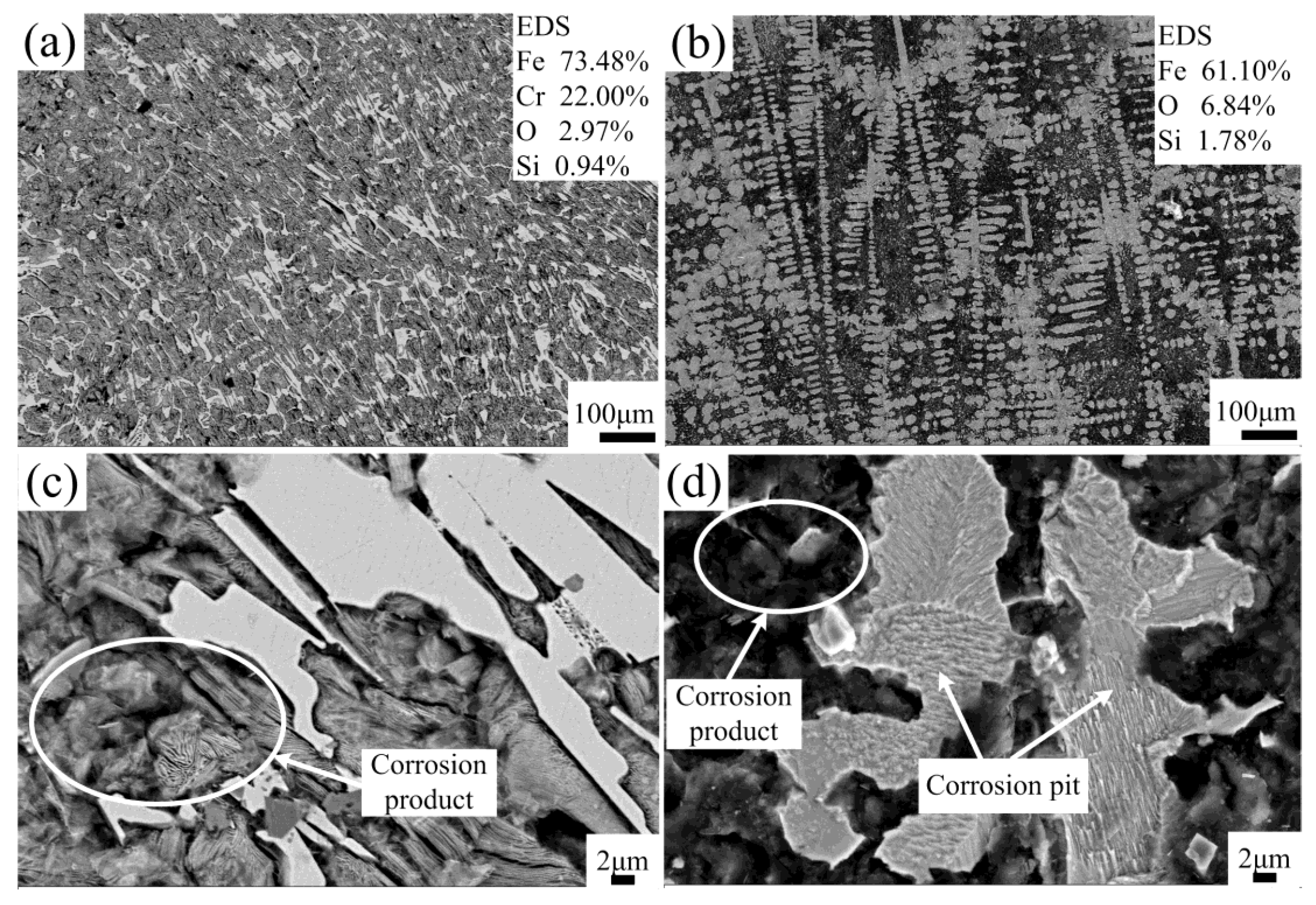
The corroded surfaces of coating and substrate are shown in Figure 13. The continuous and compact oxide products attach to the coating surface, whereas the oxide products of substrate loosely covers the surface and a sever corrosion pit occurs. In the coating, the phase composition α-(Fe, Cr) has larger negative potential than Fe3C and (Cr, Fe)7Cr3, resulting in the formation of galvanic cell in NaCl solution. Therefore, the matrix α-(Fe, Cr) is corroded first, and referring to the element composition of the corroded surface of coating, it can be presumed that the oxide film is primarily composed of Cr2O3 so as to reduce electrode passivation of the coating [22].

3.5. Friction and Wear Properties

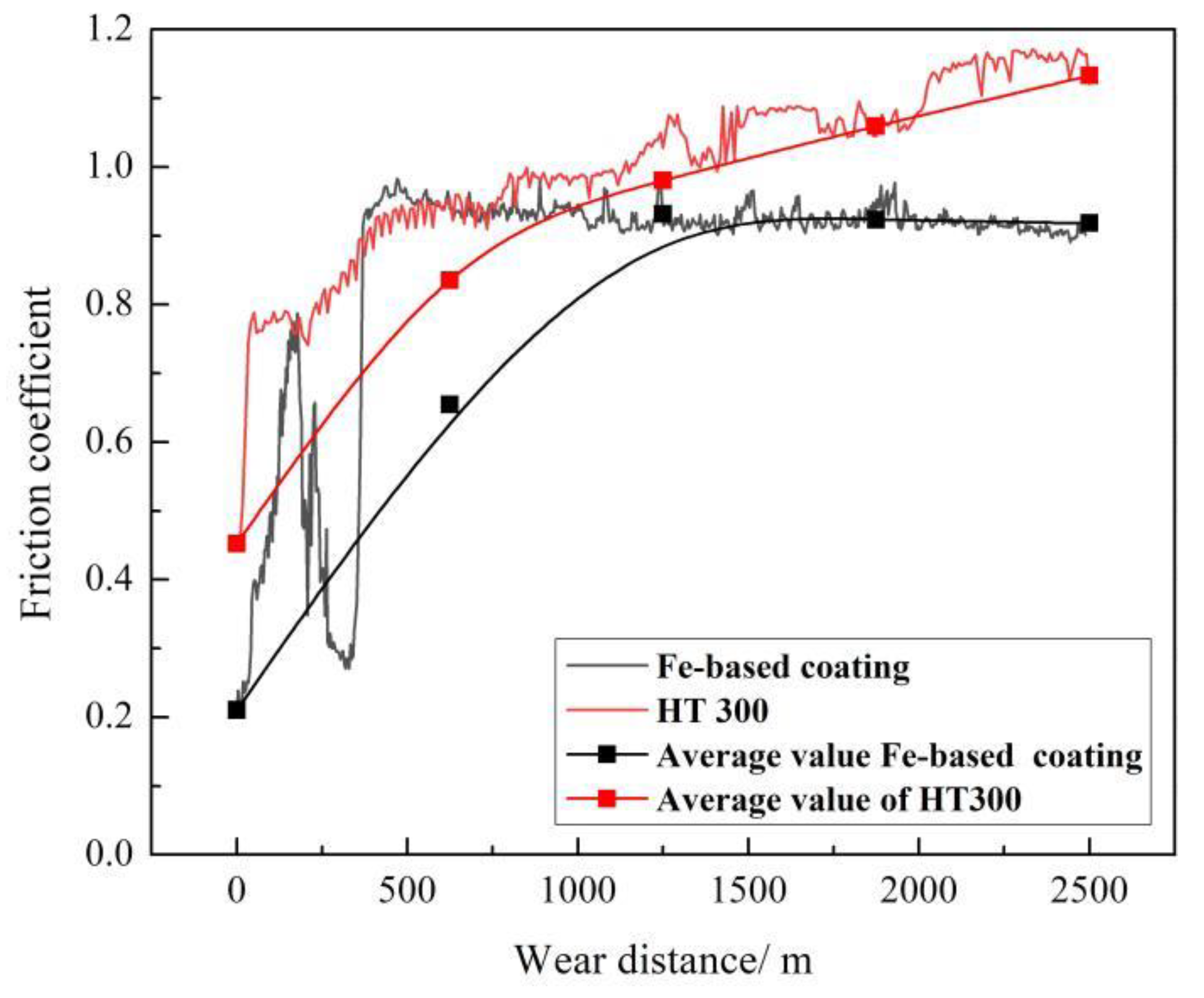
Figure 14 shows the functional relationship between friction coefficient and sliding distance. It can be observed that the friction coefficient of coating violently fluctuates and increases at the beginning of friction process at the sliding distance from 0 to 625 m and then gradually tends to be stable at approximately 0.9. By comparison, the friction coefficient of substrate quickly goes upwards at the first sliding distance of 625 m, and then, it continuously increases. At the sliding distance before 625 m, the friction coefficient of coating changes more severely than the substrate at some sliding distance intervals, however, after sliding distance of 625 m, the friction coefficient of coating tends to stabilize at lower values.
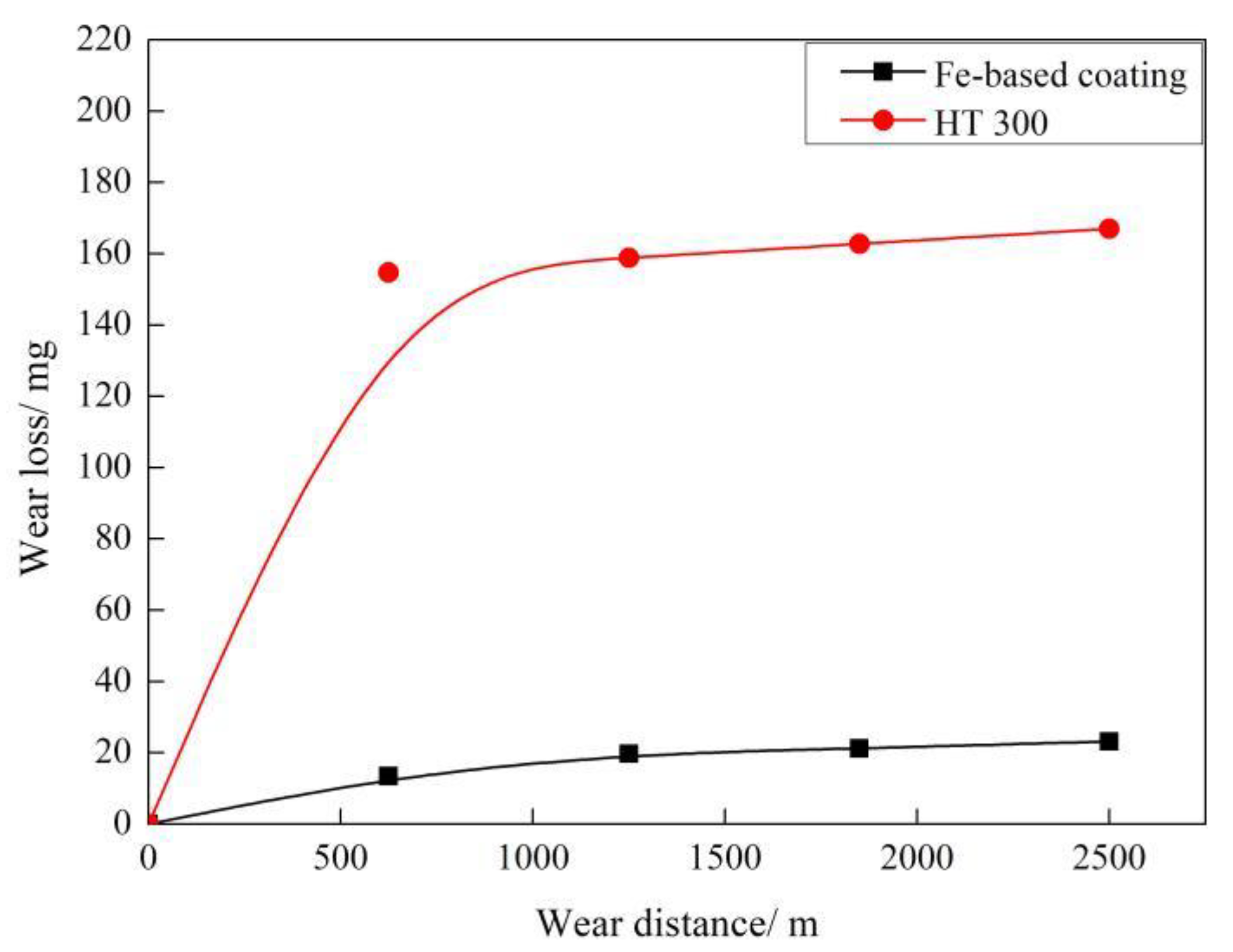
The variations of wear loss with distance are plotted in Figure 15. In the whole friction process, the wear loss of both coating and substrate increases with sliding distance, whereas the coating has much lower wear loss than the substrate, nearly one-seventh of the substrates. Furthermore, the wear loss increment of coating at each 625 m intervals is relatively smaller compared with the substrate. Based on the analysis of friction coefficient and wear loss, it can be seen that the antifriction and wear resistance properties of the coating are well concordant, and so, it exhibits a great potential to improve the tribological property of cylinder liner.
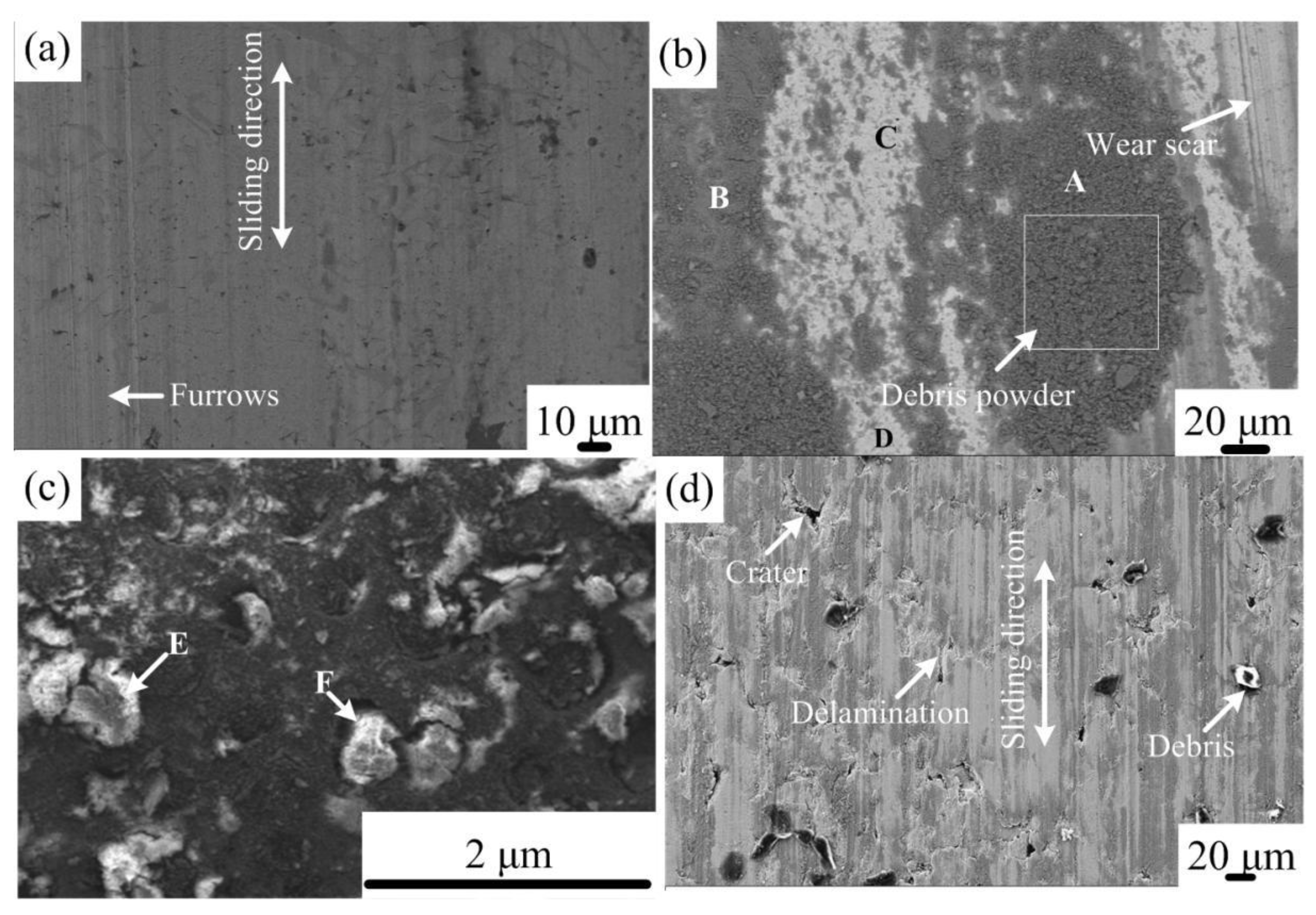
The morphology of worn surface of coating is shown in Figure 16a–c. After the sliding distance of 625 m, minor furrows appear along the friction direction on the coating surface, and the wear mechanism in this stage is dominated by light abrasive wear. When the sliding distance reaches 2500 m, the deep groove occurs and a quantity of wear products cover on the coating surface. Meanwhile, some spots of debris powder are agglomerated onto the coating surface. Referring to the EDS results (Table 5), the dark region and wear debris primarily consist of oxides, and the white region consists of the original chemical composition of Fe-based coating. With the increase in sliding distance, the wear debris is oxidized under the role of friction heat and air and firmly attached onto the coating surface. In accordance with the analysis of wear behavior, it can be observed that after the sliding distance of 625 m, the friction coefficient of coating tends to be stable and the wear losses increase slowly. It can be assumed that the wear products firmly cover on the coating surface, which, in turn, improve the wear resistance [23]. To conclude, the wear mechanism of coating is mainly dominated by abrasive wear and oxidation wear. In contrast, the worn surface of substrate suffers sever adhesive wear, presenting plastic deformation and deep groves after sliding distance of 2500 m, as shown in Figure 16d. Some small craters and large size debris can be obviously seen on the coarse wear surface of substrate. Because the graphite flakes and the matrix around the graphite flakes can be easily peeled off, rough wear surface and some craters are generated, which, in turn, lead to the violent fluctuation of friction coefficient and a high mass loss. The main wear mechanism of the substrate is the predominant fatigue wear [24].

4. Conclusions

The Fe-based coating was successfully fabricated on gray cast iron by the additive of welding flux in the Fe-based alloy powder and prolonging the heating time using induction cladding. The coating forming mechanism, microstructure, characterization, electrochemical corrosion behavior, and tribological performance were studied. The main experimental results and conclusions are summarized as follows:
a.
Because the Fe-based alloy powder is easily oxidized during the induction cladding, the iron oxides cover outside the Fe-based alloy powder, consequently increasing the melting temperature and further hindering the heating process. The additive of welding flux can react with the iron oxides and the reaction products can fill the gaps between the alloy particles, therefore increasing the heat transfer. In addition, prolonging the heating time promotes the complete reaction of welding flux so as to reduce the gas pore in the coating. Therefore, the additive of welding flux and prolonged heating time is a feasible approach to fabricate good-quality Fe-based alloy coating onto gray cast iron.
b.
The elemental distribution at the bonding interface shows that the coating is metallurgically bonded with the substrate. The XRD diffraction pattern and SEM images reveal that the phase composition of the coating consists of α-(Fe, Cr), (Fe, Cr)7C3, and Fe3C. Due to the uneven distribution of the hard phase in the coating, the hardness curve presents fluctuation and its mean value is approximately four times higher than that of substrate.
c.
The results of potentiodynamic polarization and ac impedance testings in 3.5% NaCl solution indicate that the Fe-based coating possesses better anti-corrosion properties than gray cast iron, and the corrosion products continuously and firmly attach on the coating surface, which is beneficial for preventing the electrochemical corrosion.
d.
Friction coefficient of the coating violently fluctuates before the sliding distance of 625 m and then gradually tends to be stable at roughly 0.9, always lower than that of the gray cast iron. Wear loss of the coating increases with the sliding distance and is approximately seven times lower than that of the substrate. The wear mechanism of the coating is changed mainly from light abrasive wear to moderate abrasive and oxidation wear.

Author Contributions

Conceptualization, J.Y.; writing-review and editing, J.Y.; supervision and funding acauisition, J.Y.; methodology and software, Y.L.; investigation, data curation, writing-original draft preparation, B.S.; resources, J.W. All authors have read and agreed to the published version of the manuscript.

Funding

The authors appreciate the financial support from the National Natural Science Foundation of China (grant No. 51605066), Liaoning Province Natural Science Foundation (grant No. 2020-HYLH-22), Chinese Postdoctoral Science Foundation (grant No. 2020M670734), and Large Instruments and Facilities Shared Foundation of Dalian Maritime University.

Conflicts of Interest

The authors declare no conflict of interest.

References

  1. Guo, Z.W.; Yuan, C.Q.; Liu, P.; Yan, Y.P. Effect of cylinder surface treatment on diesel engine performance. Adv. Mater. Res. 2011, 199–200, 689–695. [Google Scholar] [CrossRef]
  2. Fu, P.; Zhao, C.; Tian, H. Experimental research and performance testing of Fe-based composite plating. Adv. Mater. Res. 2011, 221, 364–368. [Google Scholar] [CrossRef]
  3. Kumar, V.; Sinha, S.K.; Agarwal, A.K. Wear evaluation of engine piston rings coated with dual layer hard and soft coatings. J. Tribol. 2018, 141, 031301. [Google Scholar] [CrossRef]
  4. Huang, B.; Zhang, C.; Zhang, G.; Liao, H. Wear and corrosion resistant performance of thermal-sprayed Fe-based amorphous coatings: A review. Surf. Coat. Technol. 2019, 377, 124896. [Google Scholar] [CrossRef]
  5. Zhang, Q.; Zhang, P.; Yan, H.; Yu, Z.; Wu, D.; Shi, H.; Li, S.; Tian, Y. Magnetic-field-assisted laser cladding in the preparation of a crack-free Fe-Cr-Mo-C-Y-B amorphous coating on steel. Philos. Mag. Lett. 2020. [Google Scholar] [CrossRef]
  6. Bing, Z.; Shi, Y.; Sun, R.; Guo, Y. Study on microstructure and properties of 304/316L coating prepared by ultra-high frequency induction cladding with wire feeding. Surf. Coat. Technol. 2020, 387, 1–13. [Google Scholar] [CrossRef]
  7. Yu, H.; Zhang, W.; Wang, H.; Ji, X.; Song, Z.; Li, X.; Xu, B. In-situ synthesis of TiC/Ti composite coating by high frequency induction cladding. J. Alloys Compd. 2017, 701, 244–255. [Google Scholar] [CrossRef] [Green Version]
  8. Sun, G.; Zhou, R.; Li, P.; Feng, A.; Zhang, Y. Laser surface alloying of C-B-W-Cr powders on nodular cast iron rolls. Surf. Coat. Technol. 2011, 205, 2747–2754. [Google Scholar] [CrossRef]
  9. dos Santos Filho, D.; Tschipstschin, A.P.; Goldenstein, H. Effects of ethanol content on cast iron cylinder wear in a flex-fuel internal combustion engine-A cast study. Wear 2018, 406–407, 105–117. [Google Scholar] [CrossRef]
  10. Liu, J.; Liu, H.; Tian, X.; Yang, H.; Hao, J. Microstructural evolution and corrosion properties of Ni-based alloy coatings fabricated by multi-layer laser cladding on cast iron. J. Alloys Compd. 2020, 822, 153708. [Google Scholar] [CrossRef]
  11. Li, Y.; Dong, S.; He, P.; Yan, S.; Li, E.; Liu, X.; Xu, B. Microstructure characteristics and mechanical properties of new-type FeNiCr laser cladding alloy coating on nodular cast iron. J. Mater. Process. Technol. 2019, 269, 163–171. [Google Scholar] [CrossRef]
  12. Jing, Y.; Song, B. Friction and wear behavior of a Ni-based alloy coating fabricated using a multistep induction cladding technique. Results Phys. 2018, 11, 105–111. [Google Scholar]
  13. Jing, Y.; Song, B. Effects of heating time on the microstructure and properties of an induction cladding coating. Results Phys. 2018, 11, 212–218. [Google Scholar]
  14. An, Y.-J.; Zhu, L.; Li, W.-Q.; Lu, J.-J.; Liu, X.-Y. Study of fly ash-based flux effects on microstructure and wear of TIG-cladded Ni-based composite coating. Results Phys. 2019, 12, 970–974. [Google Scholar] [CrossRef]
  15. Lu, X.-L.; Liu, X.-B.; Yu, P.-C.; Zhai, Y.-J.; Qiao, S.-J.; Wang, M.-D.; Wang, Y.-G.; Chen, Y. Effects of heat treatment on micostructure and mechanical properties of Ni60/h-BN self-lubricating anti-wear composite coatings on 304 stainless steel by laser. Appl. Surf. Sci. 2015, 355, 350–358. [Google Scholar] [CrossRef]
  16. Yuan, Y.; Li, Z. Microstructure and wear performance of high volume fraction carbide M7C3 reinforced Fe-based composite coating fabricated by plasma transferred arc welding. J. Wuhan Univ. Technol. Sci. Ed. 2014, 29, 1028–1035. [Google Scholar] [CrossRef]
  17. Luo, K.; Xu, X.; Zhao, Z.; Zhao, S.; Cheng, Z.; Lu, J. Microstructural evolution and characteristics of bonding zone in multilayer laser cladding of Fe-based coating. J. Mater. Process. Technol. 2019, 263, 50–58. [Google Scholar] [CrossRef]
  18. Li, Y.; Dong, S.; Yan, S.; Liu, X.; He, P.; Xu, B. Surface remanufacturing of ductile cast iron by laser cladding Ni-Cu alloy coatings. Surf. Coat. Technol. 2018, 347, 20–28. [Google Scholar] [CrossRef]
  19. Li, Y.; Dong, S.; Yan, S.; Liu, X.; He, P.; Xu, B. Microstructure evolution during laser cladding Fe-Cr alloy coatings on ductile cast iron. Opt. Laser Technol. 2018, 108, 255–264. [Google Scholar] [CrossRef]
  20. Hu, G.; Meng, H.; Liu, J. Microstructure and elevated temperature wear behavior of induction melted Fe-based composite coating. Appl. Surf. Sci. 2014, 317, 378–384. [Google Scholar] [CrossRef]
  21. Zhang, X.-L.; Jiang, C.-P.; Zhang, F.-Y.; Xing, Y.-Z. The evaluation of microstructure characteristic and corrosion performance of laser-re-melted Fe-based amorphous coating deposited via plasma spraying. Mater. Express 2019, 9, 1100–1105. [Google Scholar] [CrossRef]
  22. Hu, G.; Meng, H.; Liu, J. Microstructure and corrosion resistance of induction melted Fe-based alloy coating. Surf. Coat. Technol. 2014, 251, 300–306. [Google Scholar] [CrossRef]
  23. Hu, G.; Meng, H.; Liu, J. Friction and sliding wear behavior of induction melted FeCrB metamorphic alloy coating. Appl. Surf. Sci. 2014, 308, 363–371. [Google Scholar] [CrossRef]
  24. Li, Q.; Zhang, Y.; Zhang, Y.; Liu, H.; Ren, H.; Zhong, Y.; Huang, X.; Huang, W. Influence of Sn and Nb additions on the microstructure and wear characteristics of a gray cast iron. Appl. Phys. A 2020, 126, 1–8. [Google Scholar] [CrossRef]
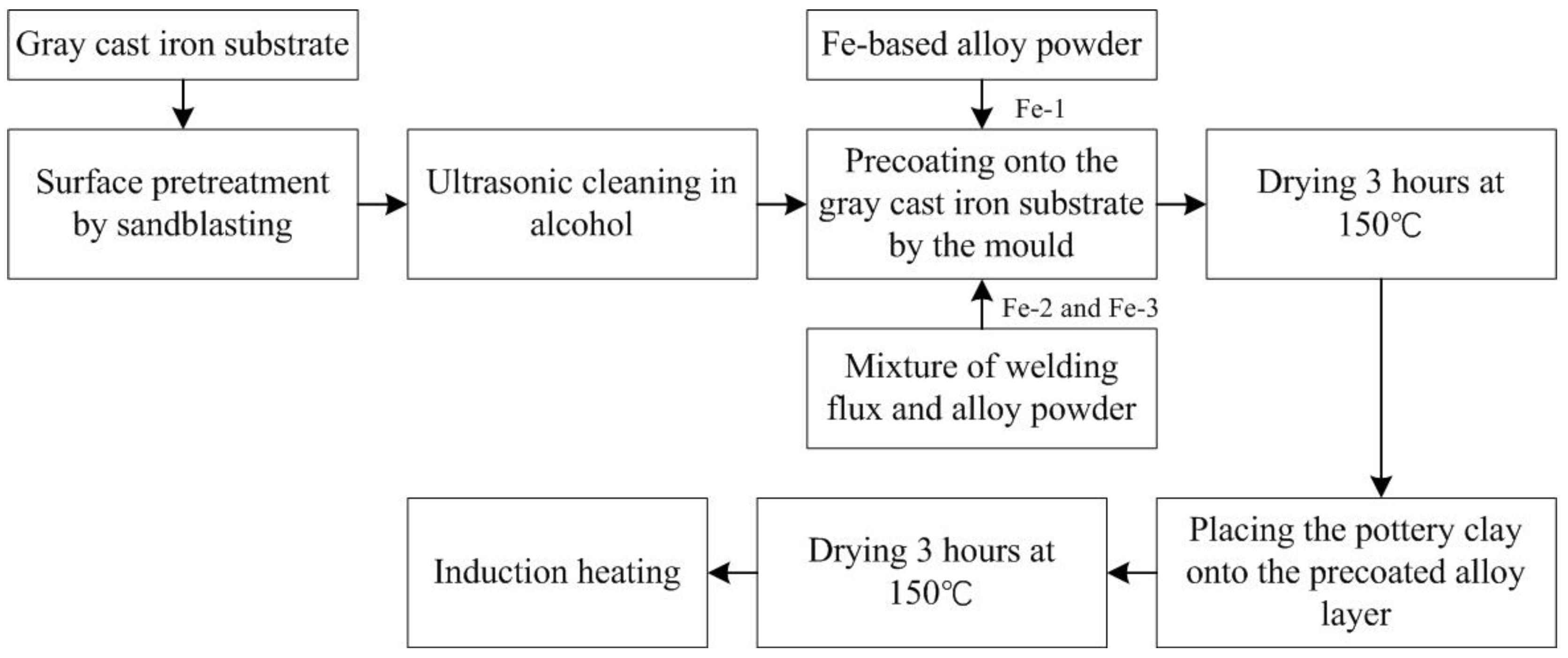
Figure 1. Induction cladding experiment procedure.
Coatings 10 00801 g001
Figure 2. (a) Coating prepared mold and (b) schematic diagram of induction cladding device.
Coatings 10 00801 g002
Figure 3. Schematic diagram of the tribo-tester.
Coatings 10 00801 g003
Figure 4. Photograph of sample Fe-1 (a) and morphology of Fe-2 (b) and Fe-3 (c).
Coatings 10 00801 g004
Figure 5. Schematic sketch and micrograph of the forming mechanism of Fe-based coating: (a) Fe-2 and (b) Fe-3.
Coatings 10 00801 g005
Figure 6. XRD result of Fe-based coating surface.
Coatings 10 00801 g006
Figure 7. Line scanning results of Fe-based alloy coating in the cross-section.
Coatings 10 00801 g007
Figure 8. SEM images at the cross-section of the coating: (a) interface of coating and substrate and (b) microstructure of the coating.
Coatings 10 00801 g008
Figure 9. Microhardness distribution from Fe-based alloy coating to the gray cast iron substrate.
Coatings 10 00801 g009
Figure 10. Polarization curves of Fe-based coating and HT 300 in 3.5% NaCl solution.
Coatings 10 00801 g010
Figure 11. Nyquist diagram of Fe-based coating and HT300 in 3.5% NaCl solution.
Coatings 10 00801 g011
Figure 12. Equivalent circuit diagram of the coating.
Coatings 10 00801 g012
Figure 13. The SEM photographs and EDS results of the corroded surfaces in 3.5% NaCl solution: (a) and (c) are Fe-based coating and (b,d) are HT 300.
Coatings 10 00801 g013
Figure 14. Friction coefficient of the coating and substrate as function of sliding distance at a given load of 100 N.
Coatings 10 00801 g014
Figure 15. Wear loss of coating and substrate as function of sliding distance at a given load of 100 N.
Coatings 10 00801 g015
Figure 16. Worn surface morphology of coating: (a) 625 m, (b) 2500 m, (c) magnified wear debris in (b), and (d) wear surface of HT 300 in the sliding displacement of 2500 m.
Coatings 10 00801 g016
Table 1. Chemical composition of HT 300 and Fe-based alloy powder in mass%.
ItemCSiMnSPCrFe
HT 3002.9–3.21.0–2.50.5–1.4≤0.5–1.0≤0.5–1.0Bal.
Fe 300.9–1.13.0–4.018–20Bal.
Table 2. Induction cladding parameters.
Sample PreheatingHeatingHeat Preservation
Current/ATime/sCurrent/ATime/sCurrent/ATime/s
Fe-110902011
Fe-210902011
Fe-3109020111030
Table 3. Polarization curve parameters of Fe-based coating and HT 300 in 3.5% NaCl Solution.
SampleEcorr (V)Icorr (µA/cm−2)Rp (Ω·cm2)Corr Rate (mm/a)
Coating−1.120110.94376.20.836
Substrate−1.037269.00106.12.251
Table 4. Electrochemical impedance spectroscopy parameters of Fe-based coating and HT 300 in 3.5% NaCl solution.
SampleRsol
(Ω·cm2)
Qdl
(F·cm−2·sn)
n1Rt
(Ω·cm2)
Qa
(F·cm−2·sn)
n2Ra
(Ω·cm2)
Coating11.840.0040.5715.030.00083440.819223.8
Substrate9.0160.0220.553.220.008040.75246.17
Table 5. EDS results of the worn surface of Fe-based alloy coating (in wt.%).
Testing PointOSiCrFe
A23.712.293.6669.72
B12.143.221.2374.34
C3.391.3395.29
D3.151.0295.83
E (wear debris)30.681.378.3359.62
F (wear debris)34.931.658.4353.55