Article

Electrodeposition of Photocatalytic Sn–Ni Matrix Composite Coatings Embedded with Doped TiO2 Particles

1
Laboratory of General Chemistry, School of Chemical Engineering, National Technical University of Athens, 9, Heroon Polytechniou Str., Zografos Campus, GR-15780 Athens, Greece
2
Department of Materials and Manufacturing, School of Engineering, Jönköping University, P.O. Box 1026, Gjuterigatan 5, SE-551 11 Jönköping, Sweden
3
Elplatek A/S, Bybjergvej 7, DK-3060 Espergærde, Denmark
*
Author to whom correspondence should be addressed.
Coatings 2020, 10(8), 775; https://doi.org/10.3390/coatings10080775
Submission received: 2 July 2020 / Revised: 30 July 2020 / Accepted: 6 August 2020 / Published: 9 August 2020
(This article belongs to the Section Surface Characterization, Deposition and Modification)

Abstract

:
Direct current electrodeposited Sn–Ni/TiO2 nanostructured coatings were produced by embedding two different doped types of TiO2 particles within the alloy matrix, a commercially available doped carbon-based and doped N,S-TiO2 particles. The structural characteristics of the composite coatings have been correlated with the effect of loading, type of particles in the electrolytic bath, and the applied current density. Regardless of the type of doped particles TiO2, increasing values of applied current density resulted in a reduction of the co-deposition percentage of TiO2 particles and an increase of Tin content into the alloy matrix. The application of low current density values accompanied by a high load of particles in the bath led to the highest codeposition percentage (~3.25 wt.%) achieved in the case of embedding N,S-TiO2 particles. X-ray diffraction data demonstrated that in composite coatings the incorporation of the different types of TiO2 particles in the alloy metal matrix modified significantly the nano-crystalline structure in comparison with the pure coatings. The best photocatalytic behavior under visible irradiation was revealed for the composite coatings with the highest co-deposition percentage of doped N,S-TiO2 particles, that also exhibited enhanced wear resistance and slightly reduced microhardness compared to pure ones.

Graphical Abstract

1. Introduction

Over the last years, TiO2 as an n-type wide bandgap semiconductor has become one of the most widely known photocatalysts for supplying solutions to environmental issues. Additionally, TiO2 photocatalytic products like self-cleaning glass and surface sterilization tools have been proven to be efficient and of great value for the applications that they are oriented [1].
The photocatalytic activity depends on the bandgap energy of materials [2]. TiO2 with anatase and rutile phases exhibits a bandgap value of 3.2 and 3.0 eV, respectively [1]. Therefore, TiO2 is known to possess photocatalytic properties in UV-light irradiation, whereas by adding different elements into TiO2 structure, doping agents change the material properties to provide photocatalytic activity in visible light [3,4]. Despite the type of TiO2 (anatase and rutile TiO2 are most often reported as photocatalysts), bulk TiO2 has little photocatalytic ability. TiO2 nanocrystals have several advantages over their bulk counterparts in terms of potential applications due to their high surface-to-volume ratio, increased number of delocalized carriers on the surface, improved charge transport and lifetime afforded by their dimensional anisotropy, and the efficient contribution in the separation of photo-generated holes and electrons [1] (p. 2140).
To fabricate nano composite coatings exhibiting photocatalytic behavior, such as nanocomposite coatings with homogeneous dispersion of semiconductor particles (i.e., TiO2) in a metal matrix, the utilization of electrodeposition has been established as a cost-effective technique, operating at temperatures close to ambient with no limitation on the shape of the substrate. It has been proven that the photocatalytic activity of the TiO2-based composite coatings depends on the nature of the matrix, specifically for the metal matrix composites that promotes the photocatalytic effect [5,6,7].
Electrodeposited Tin-nickel alloys are widely used in the metal finishing industry and microelectronics due to their attractive features, such as bright appearance and corrosion resistance [8,9]. In particular, since they are non-allergic to the skin, they can replace nickel electrocoating on fasteners for garments. Additionally, they can replace chromium in decorative and light engineering industries [10,11,12,13].
The properties of the electrodeposited composite coatings depend on process parameters, such as electrolyte composition, the presence of additives, electrolyte pH value, type of applied current (direct or pulse), deposition current density, the induced hydrodynamic conditions, as well as the characteristics of the reinforcing particles (size, conductivity, surface charge, etc.) and their concentration in the bath [7,14,15].
In this work, Sn–Ni/TiO2 electro-coatings were produced by embedding two different types of TiO2 particulates within the alloy matrix. The particles used were commercial available doped carbon-based ones and co-doped N,S-TiO2 particles produced within this study, both active under visible illumination. Under direct current (DC) conditions, the effect of the loading and type of particles in the electrolytic bath, and applied current density on the structural characteristics (surface morphology, crystallographic orientation) as well as the photocatalytic performance of the composite coatings have been investigated. Additionally, microhardness and wear resistance properties were studied for the composite coating demonstrating the best photocatalytic behavior.
The aim of this study is to design a functional composite Sn–Ni matrix coating enhanced by chemically-modified TiO2 particles photoactive under visible irradiation for self-cleaning applications such as every day hypoallergenic touching objects like knobs, handles, etc. Hence, the objective of this study is twofold: (a) estimate the optimum electrodeposition parameters by tuning applied current density and particles’ loading in the bath that result to the production of composite Sn–Ni/doped-TiO2 nano-coatings with high co-deposition percentage of particles dispersed into alloy metal matrix, and (b) investigate the correlation between compositional and morphological characteristics of the produced surfaces with the observed photocatalytic performance under visible light, taking into consideration that the proposed coatings should preserve attractive appearance, high hardness and wear resistance in comparison with pure Sn–Ni ones. It is worth mentioning that the electrodeposition of coatings reinforced by TiO2 particles has been widely investigated in nickel matrix [6,7,14,16,17] and quite a few in alloy metal matrix [18,19,20]. Very limited studies appeared in literature concerning Sn–Ni/TiO2 electrodeposition [21], while up to the knowledge of the authors no similar work regarding co-electrodeposition of chemically modified TiO2 particles in Sn–Ni matrix, and the study of photocatalytic behavior and mechanical properties of this kind of electro-coatings exists.

2. Materials and Methods

Pure Sn–Ni and composite Sn–Ni/doped-TiO2 coatings were deposited under direct current conditions (DC) from a commercial chloride fluoride-based Tin-nickel solution Galvaloy NS11 provided by Elplatek A/S (Espergærde, Denmark). The current density operational window of the bath is in the range of 0.1 up to ~5 A/dm2 and the plating speed is approximately 0.5 μm/min at 2.5 A/dm2. The electrodeposition experiments were conducted under conditions as described in Table 1. A two-electrode set up was used for deposition experiments. The solution temperature was maintained at 70 ± 1 °C. The cathode material was brass plates mechanically pretreated before each experiment and the anode was soluble and consisted of a nickel plate of 99.9% purity. The pH of the bath was adjusted to constant values in the range of 4.2–4.4, before each electrodeposition experiment.
During plating, Tin(II) is consumed by the reduction to Tin at the cathode but not replaced by the anodic dissolution given that the anode is pure nickel. Tin is also partially oxidized to Tin (IV) at the anode or by spontaneous reaction in contact with oxygen. Therefore, the Tin (II) concentration decreases rapidly and consequently, its concentration should be measured daily by titration. To compensate the decrease of Tin(II) concentration, Tin chloride was added along with proper amounts of fluoride additive according to the instructions given by the supplier company. The monitoring of Ni ions concentration was also controlled by titration. More specifically, in order to electrodeposit pure Tin-nickel coatings with 65 wt.% Tin and 35 wt.% nickel, the Tin content in the bath was always maintained in the range of 20–25 g·L−1, while nickel was in the range of 55–65 g·L−1 by adding appropriate amounts of Tin chloride and nickel chloride, respectively. In the case of composite coating, the Tin and nickel content in the electrolyte was monitored as described above for pure coatings in order to maintain the same weight ratio in the electrolyte.
In order to verify deposition current efficiency and the corresponding electrodeposition time, the samples were weighed before and after the deposition took place and the real deposited mass has been compared to the theoretical one calculated by the Faraday law. It was found that the current efficiency was almost 100% for all samples and the time of electrodeposition was adjusted using Faraday’s law so that the thickness for both pure and composite coatings was ~5 μm.
The composite Sn–Ni/doped TiO2 coatings were produced by immobilizing two different kinds of doped-TiO2 particulates within the alloy matrix. The commercially available Kronos (Kronos International Inc., Leverkusen, Germany) vlp 7000 particles are carbon-doped anatase with 87.5 wt.% TiO2, aimed to be active in visible with crystallites exhibiting a surface morphology depicted in Figure 1a,b. The other type of particles is N,S-codoped TiO2 particles which were synthesized within this study by hydrolysis through the sol-gel route using titanium(IV) butoxide as precursor and thiourea as doping agent aimed to be active also in visible illumination [22]. The typical morphology of the produced N,S- co-doped particles is shown in Figure 1c,d. The average doped TiO2 crystallites size for both types of TiO2 particles was estimated by X-ray diffraction data as deduced by the application of Scherrer’s formula [23] for the strongest diffraction peak at 2θ ≈ 25.3°, which is representative for (101) anatase phase reflections. (see Figure 2a,b), revealing a size of ~15 and 10 nm for Kronos vlp 7000 and N,S-codoped TiO2 particles, respectively. Moreover, in Figure 1, it is possible to detect for both types of doped titania grains with a relative wide distribution of size, ranging from a few tens to hundreds of nm, with a tendency of agglomeration. Hence, the used doped TiO2 powders could be characterized as nanocrystalline with a mean particle size in the submicron scale.
Doped-TiO2 particles were maintained in suspension by pumping recirculation for at least 24 h before deposition, as well as during electrodeposition. The load of particles in the electrolytic bath was set at 10, 20, and 30 g·L−1 and the applied current density varied from 1 to 5 A·dm−2.
Field emission SEM (JSM-7001F and JSM -7401F, JEOL, Tokyo, Japan) was applied to study the morphology and composition of coatings’ surface. The concentration of doped-TiO2 particles embedded in the alloy matrix was evaluated by using energy-dispersive X-ray spectroscopy (EDS) measurements (FEI Quanta 200, Thermo Fischer Scientific, Hillsboro, OR, USA.
The structural properties of the coatings, as well as of the used TiO2 powders, were examined by X-ray diffraction data analysis obtained by using a Siemens (Munich, Germany) D-5000 diffractometer with a Cu Kα radiation. Diffractograms for the produced coatings were recorded with a step size of 0.2° for 2θ ranging from 20° to 80°, while the powders were scanned with a slower scan rate, a step size of 0.02° from 20° to 80°. The grain size of the coatings crystallites was determined by using the (102) X-ray diffraction peak broadening according to the Sherrer equation.
The roughness values of the as-deposited samples were measured with a surface roughness Tester (Homel Tester T1000, Hommel Werke GmbH, Vilingen-Schwenningen, Germany).
The photocatalytic activity of both pure and composite coatings was evaluated under appropriate visible illumination. Daylight UV-A irradiation was provided by four parallel Sylvania 15 W daylight lamps (350–750 nm, 3 mW·cm−2) with a 400 nm cutoff filter into a laboratory constructed photo-reactor (50 cm × 40 cm × 30 cm in dimensions) placed at a distance of 10 cm from the cylindrical round-bottomed Pyrex photocatalytic cells. The irradiance of the system was measured using a 28-0925 Ealing Research Radiometer Photometer (Ealing UG, Rodgau, Germany) operating in conjunction with a 28-0982 silicon detector and a 28-0727 flat response filter. Methylene blue (MB) and Rhodamine B (RhB) were used as pollutants for photocatalytic degradation under visible light irradiation. The coatings surface was carefully adjusted to 1 cm2 and was immersed in 5 mL aqueous solution of MB and RB of initial concentration 4.7 × 10⁻⁶ and 7.6 × 10⁻⁶ M, respectively. Before each photocatalytic run, the solution was saturated in oxygen by bubbling O2 gas for 2 h. Afterwards, all the tested samples immersed in the saturated solution were kept stirring by using a magnetic stirrer prior irradiation in the dark for 1 h to achieve adsorption/desorption equilibrium. All the photocatalytic experiments were performed under continuous stirring and conducted at three different samples for each type of tested coating. MB solutions display maximum absorbance at 664nm while RB at 554 nm, therefore temporal changes on the concentration of the corresponding pollutant were monitored every 20 min by examining the variations of intensity at the aforementioned absorption bands recorded at the spectrometer UV-Vis (U-2001, Hitachi, Tokyo, Japan).
The hardness and Young’s modulus of specific pure and composite coatings were evaluated by using a Nano TestTM Vantage nano-indenter (Nano TestTM, Whexham, UK), operated with a Berkovich diamond tip, up to a normal load of 20 mN, applied for 10 s with a load rate of 1 mN/s.
Tribological properties of the coatings were studied by performing ball-on-disc measurements using a CSM tribometer (CSM Instruments, Portland, OR, USA operating under dry sliding conditions. The coefficient of friction was automatically recorded. The applied tribological experimental conditions are summarized in Table 2. The wear tracks were studied by using electron microscopy (JSM -6390, JEOL, Tokyo, Japan) and a laser-type optical profilometer (3D profilometer, Bruker, Billerica, MA, USA). The volumetric wear factor (cw) was calculated using the following equation:
cw = V/FS (cm3/Nm)
where V is the volume loss determined by the aforementioned profilometer, F is the applied load, and S is the total sliding distance.
Each electrodeposition experiment was repeated at least three times and the produced coatings were examined accordingly.

3. Results and Discussion

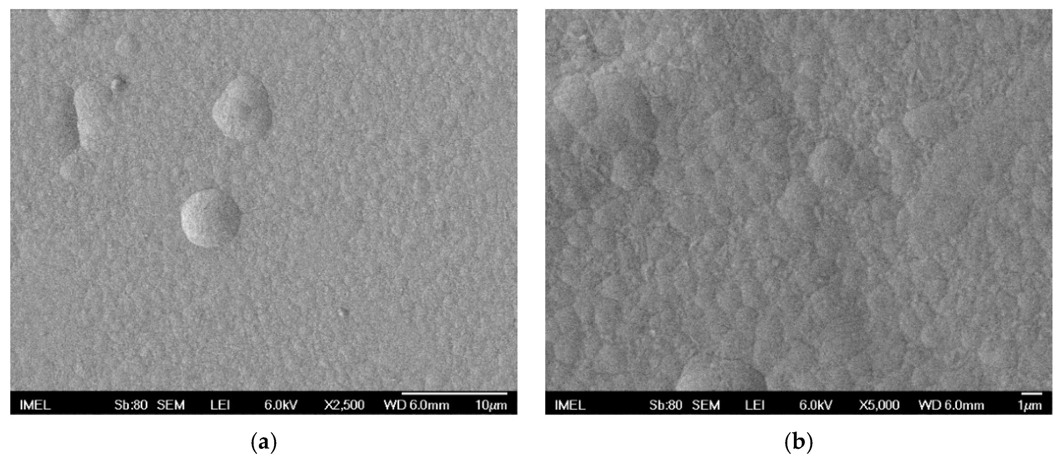
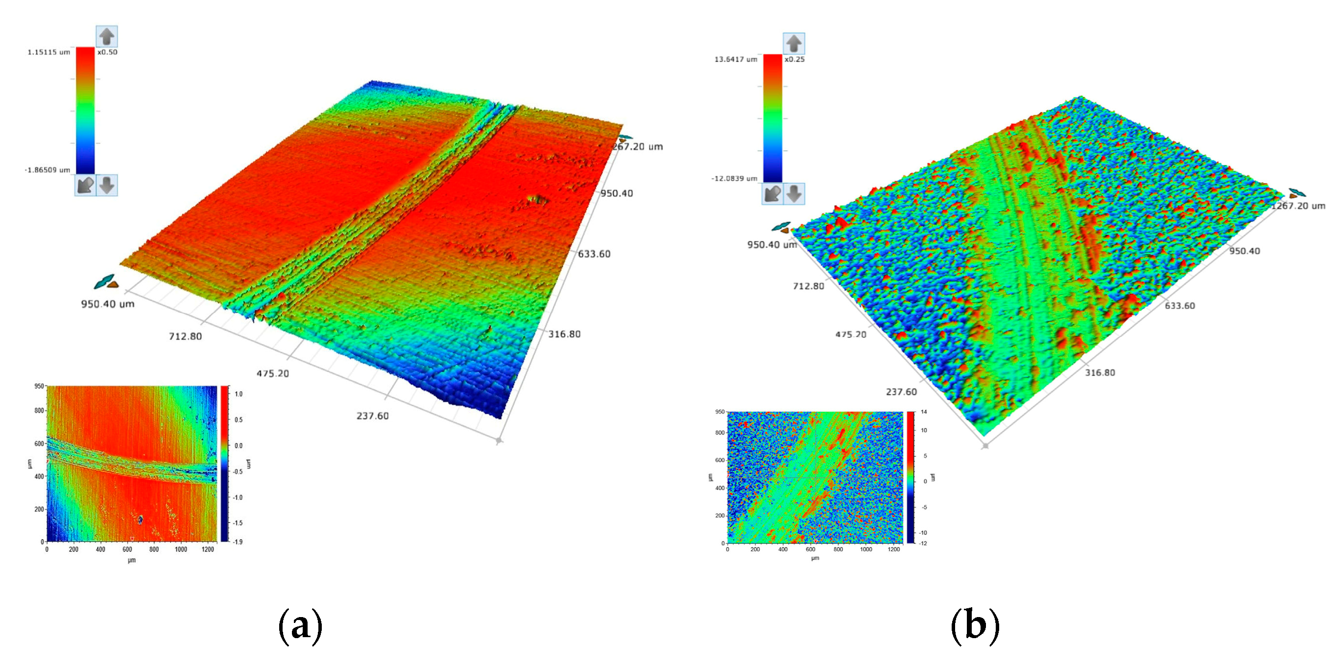
3.1. Deposition of Pure Sn–Ni Coatings

DC electrodeposition of pure Sn–Ni coatings was realized by variation of current density value from 1 up to 5 A·dm−2 accompanied by non-significant changes in the coating composition. According to EDS analysis, the Sn-Ni ratio is close to the desired composition 65 wt.%–35 wt.% and as the deposition current density increases the Sn content in the deposit increases as well reaching the maximum value of ~67 wt.% It has been reported that in the Sn–Ni binary system hydrogen evolution presumably inhibits the co-deposition of nickel; hence Tin content could slightly increase [24,25,26].
X-ray Diffraction analysis of pure coatings electrodeposited at various current density values (Figure 3) shows the main peak at 2θ ≈ 43.6°. This peak is attributed to the metastable phase NiSn which is not listed in the standard equilibrium phase diagram [27] and exhibits a NiAl-type hexagonal structure [28]. The low-intensity peak at 2θ ≈ 80° is attributed to Sn while the other two peaks at 2θ ≈ 48° and 2θ ≈ 95° to the brass substrate [24,27,29].
Sn–Ni alloy coatings with approximately 65 wt.% Sn content formed by the application of electrodeposition demonstrates significant differences in the equilibrium structure [29]. It has been already ascertained from previous studies that electroplating leads to the formation of metastable phases, while the formation of metastable NiSn was related to the increased free energy of formation of the stable two-phase mixture deriving from the high activation energy of the discharging cations due to the high temperature of operation >65 °C [28]. It was also suggested that the enlargement of the composition range for the metastable NiSn concerning the stable phase Ni3Sn2 could be explained by a change of the lattice occupancy probability by Ni atoms [27].
The X-ray diffraction data of this study depicted that increasing values of applied current density is accompanied by a decrease of the intensity of the main metastable NiSn peak, possibly due to small variations of Sn content in the alloy that could be associated with a variation of the solubility of Sn in the metastable phase [27].
The surface morphology of pure Sn–Ni deposits is characterized as nodular [29] (see Figure 4), and consisted of spherical grains with various sizes along the surface as depicted in Figure 4b at higher magnification.

3.2. Influence of Doped-TiO2 Particles on Tin-Nickel Electrocrystallization

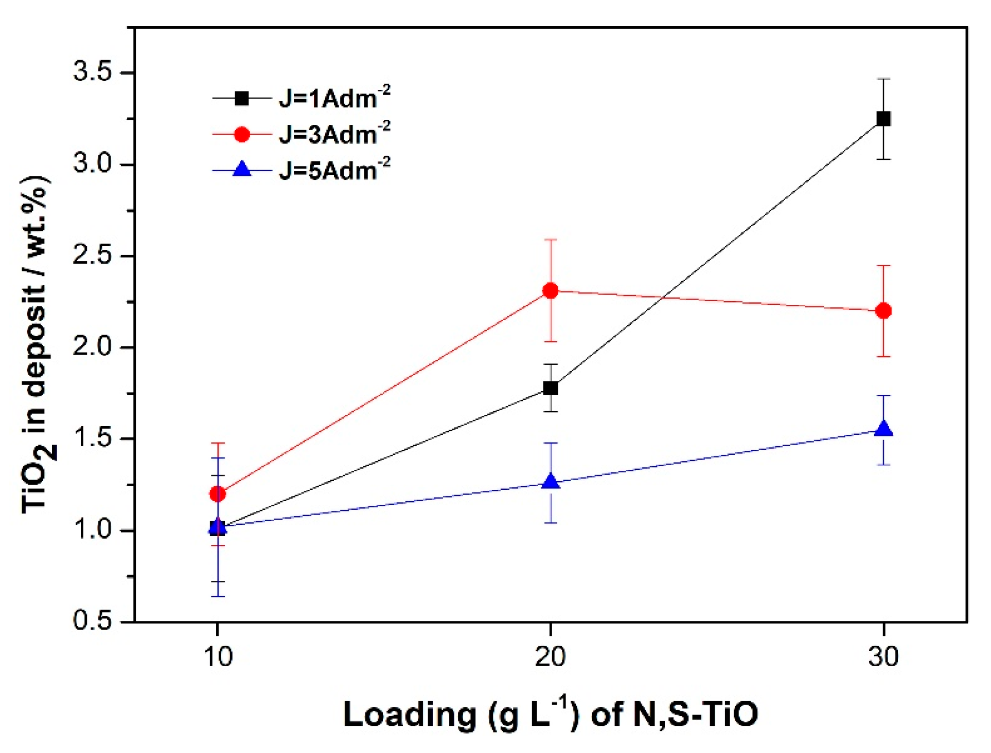
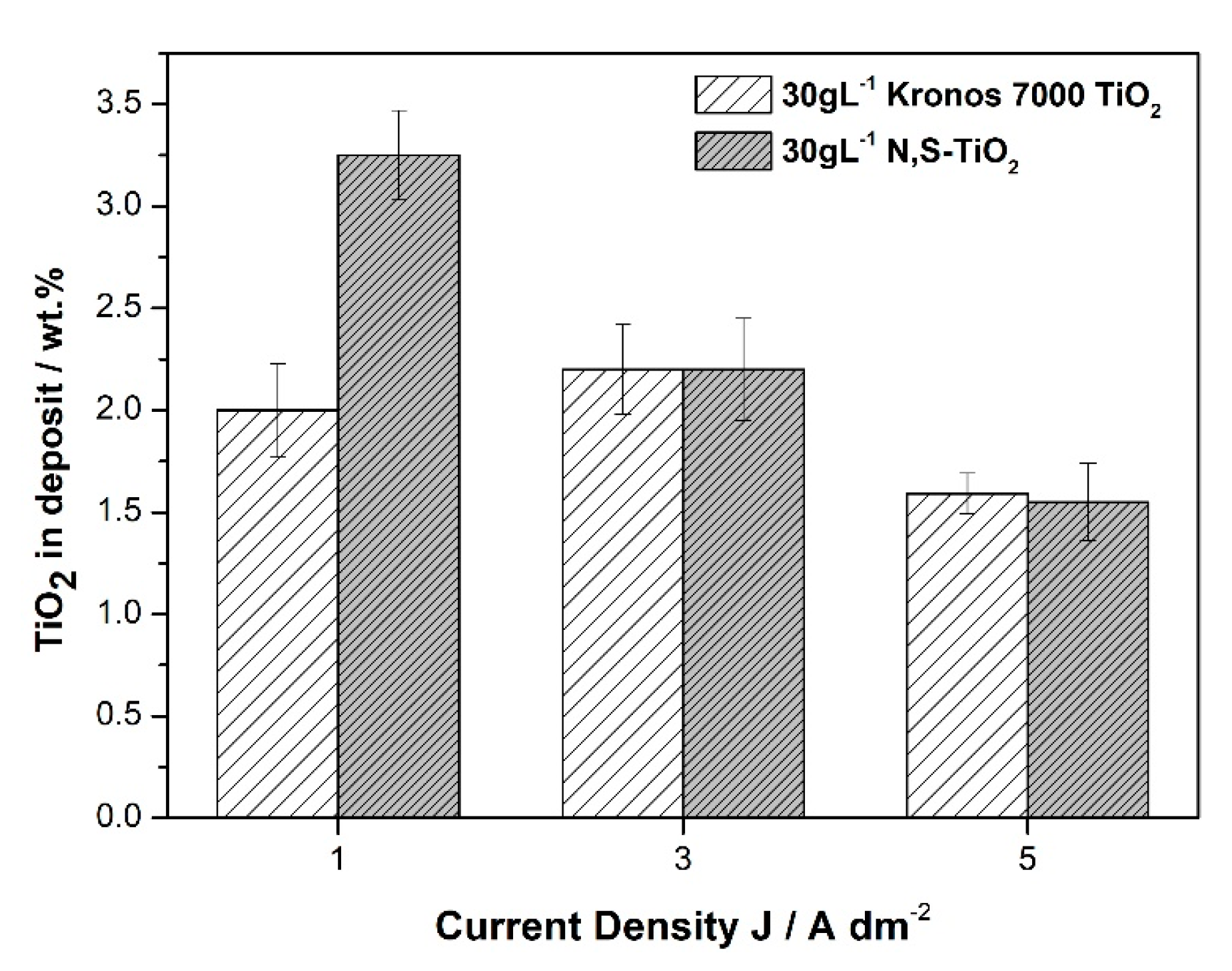
3.2.1. TiO2 Doped-Particles Co-Deposition Percentage

In this study selected deposition parameters were varied to define the optimum alloy matrix composite coatings produced under direct current conditions. Two different types of TiO2-based particles were used known as efficient photocatalyst operating under visible illumination, the one is the commercial Kronos vlp 7000 and the doped N,S-TiO2 particles produced by the research team in lab scale. Different current densities were also applied from 1 to 5 A·dm−2 to verify how this electrodeposition parameter affects the particles’ co-deposition rate. Additionally, the concentration of N,S-TiO2 particles in the electrolyte was set at 10, 20, and 30 g·L−1 to investigate the correlation between loading of particles with the co-deposition rate in the composite coatings.
The effect of the value of applied current density on the weight co-deposition percentage of the doped N,S-TiO2 at a constant concentration of 30 g·L−1 of particles in the electrolyte is presented in Figure 5a.
Apparently, the increase in current density values does not enhance the co-deposition of doped-TiO2 particles in the coating. The highest co-deposition percentage, 3.25 wt.% N, S-TiO2-(or 7.12% vol)., is achieved at the lowest current density value of 1 A·dm−2. It seems that the low value of current density associated with lower rate growth of alloy crystallites favors the efficient embedding of particles in the alloy metal matrix. This is in agreement with previous studies on composite Ni/TiO2, where they observed that at constant pH value, the embedding of TiO2 particles increases by decreasing current density value [14]. Similar results have been demonstrated in the case of Ni-Al2O3 [30] and Ni-SiC [31]. According to Fransaer et al., a particle “group” will be engulfed by the growing metal when brought in contact with an electrode with enough foothold to remain on the electrode. A situation that could give this opportunity to the particles to be efficiently embedded in the matrix could be achieved at low current densities [32] (p. 413). Additionally, it has been reported that according to Guglielmi theoretical model and experimental findings proving that that high current values of current density are disadvantageous for nanostructured composites indicating that the first loose adsorption step of particles is less sensitive to the current that the metal ions and therefore high current increases the reduction of metals against co-deposition of particles in the matrix [31,33].
Figure 5b demonstrates that the applied current density affects simultaneously the composition of the alloy matrix apart from the co-deposition rate of particles. Increasing values of applied current density from 1 to 5 A·dm−2 leads to increasing tin content values compared to the corresponding nickel ones in the alloy. Similar variations have already been mentioned for the case of pure coatings (see Section 3.1). However, the alteration of the composition 65 wt.%–35 wt.% of the alloy matrix with increasing current density is more pronounced when it comes to composites. Nevertheless, it should be expected that increasing amounts of embedded doped-TiO2 particles could impart also modification in the composition of the alloy matrix. It seems that it is more significant the effect of increasing current density on the alloy composition rather than the increasing amounts of particles embedded in the alloy [34]. For instance, the change in the composition of the alloy favoring the Tin content is more pronounced at the highest applied current density, 5 A·dm−2 (Figure 5b) where the lowest co-deposition percentage of particles (Figure 5a) is achieved (1.55 wt.% TiO2). Overall, it seems that the optimum applied current density value is that of 1 A·dm−2 leading to the highest co-deposition rate of particles in the alloy. The effect of the concentration of the particles in the electrolyte on the co-deposition percentage of N,S-TiO2 particles is presented in Figure 6 for different current density values.
In general, increasing loading of particles is accompanied by an increment of embedded particles where the highest percentage is achieved at 30 g·L−1 TiO2 loading and current density 1 A·dm−2 following data of Figure 5a. It should be noticed that at mean current density values (3 A·dm−2) at high loadings (20 and 30 g·L−1 TiO2) maximum values are achieved. It seems that under these plating conditions no further increase of codeposition rate is expected regardless of any increase of loading, indicating a saturation of the co-deposited particles in the alloy matrix. These findings are in agreement with relative studies in composite electro-coatings in the Ni matrix [7,14] and alloy matrix [34]. At high current densities the movement of the metallic ions towards the cathode is faster and consequently the deposition of the metallic ions is higher than the particles transport to the cathode and thus lower incorporation rates are achieved [34].
Comparing the co-deposition percentage for two different TiO2 based particles under different current density values at constant loading in the bath it is verified that high current density values are accompanied by the lowest embedding rates of particles (Figure 7).
It should be mentioned that in the case of Kronos powder there is no significant alteration in TiO2 embedded particles percentage achieved at 1 and 3 A·dm−2 that could be associated with a different co-deposition mechanism of particles in the alloy matrix, originated by the different chemical and physical properties of the particles since the commercially available Kronos powder includes different carbon-based dopants. Overall, the optimum values for achieving high co-deposition rates of particles for both powders are estimated at low current density values (1 A·dm−2) and 30 g·L−1 concentration of particles in the electrolyte under direct current conditions.

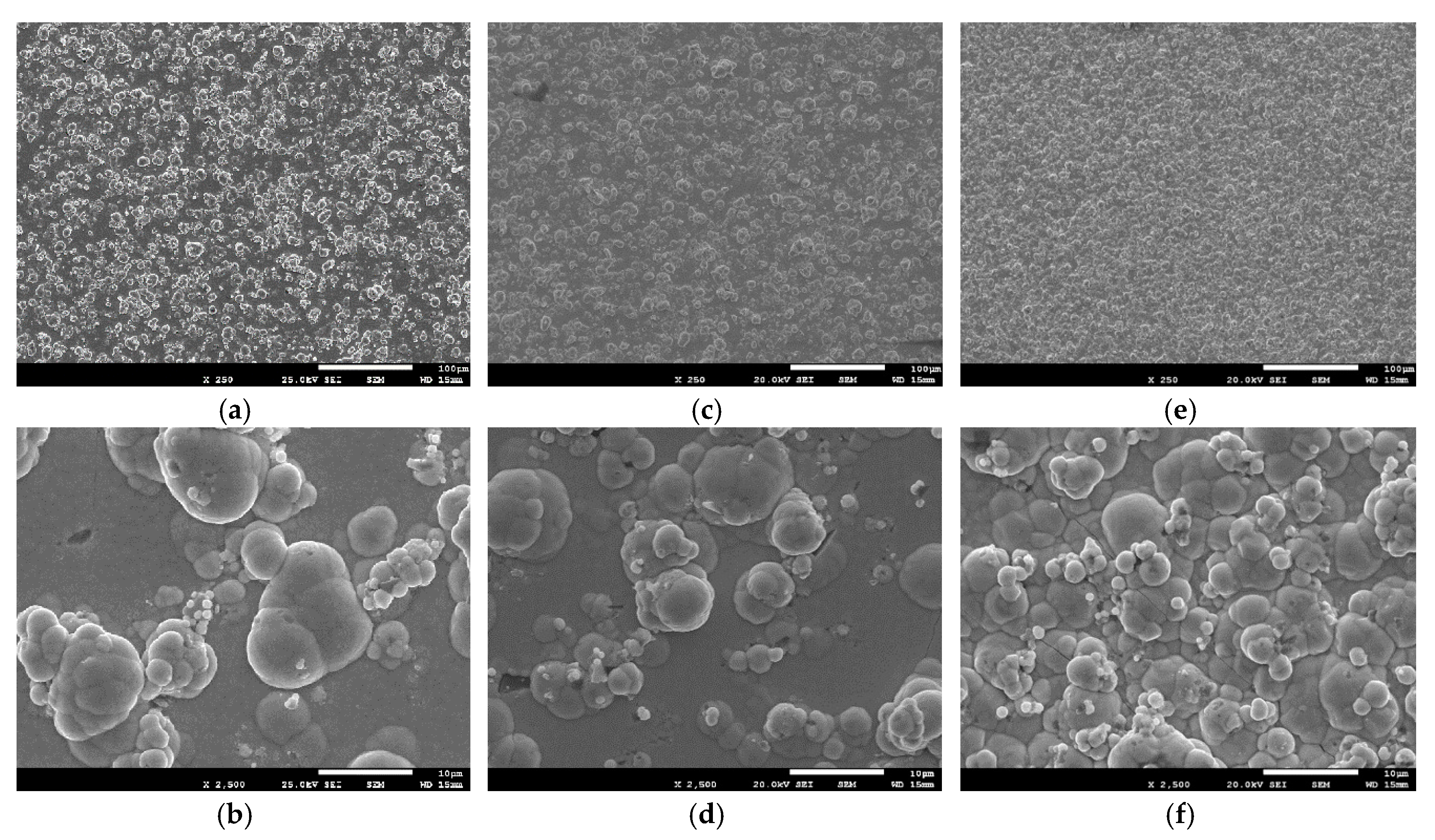
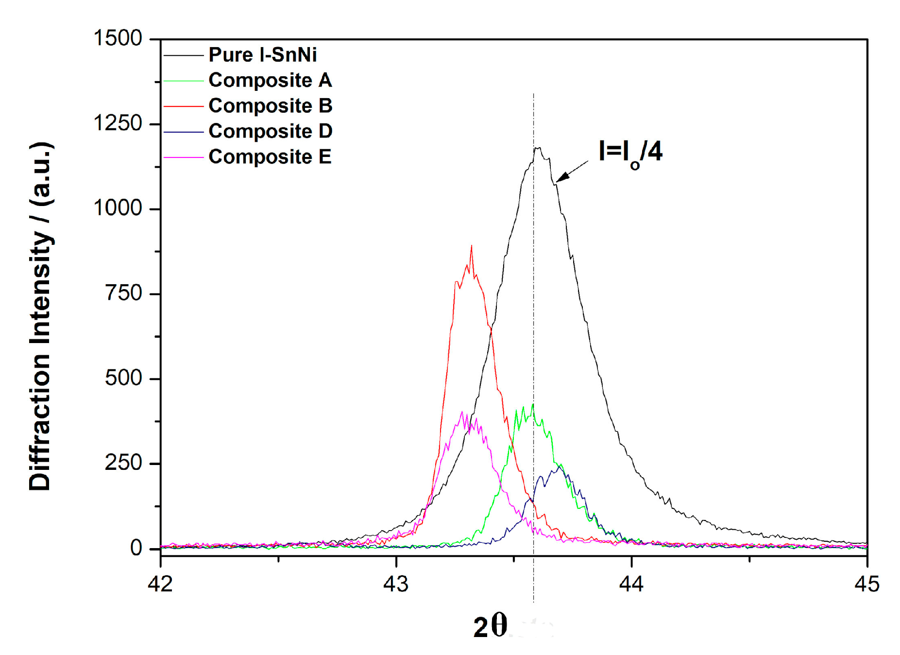
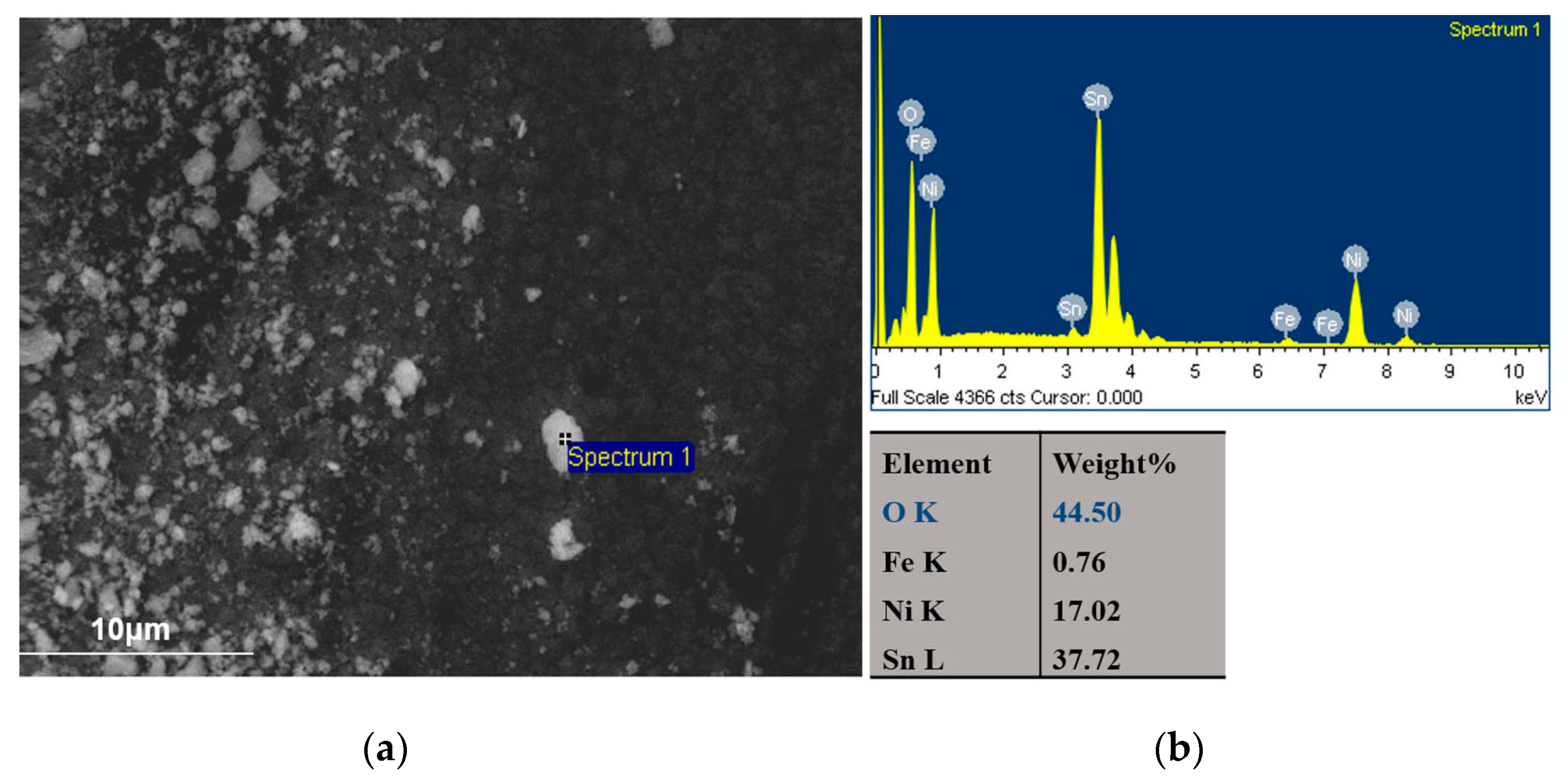
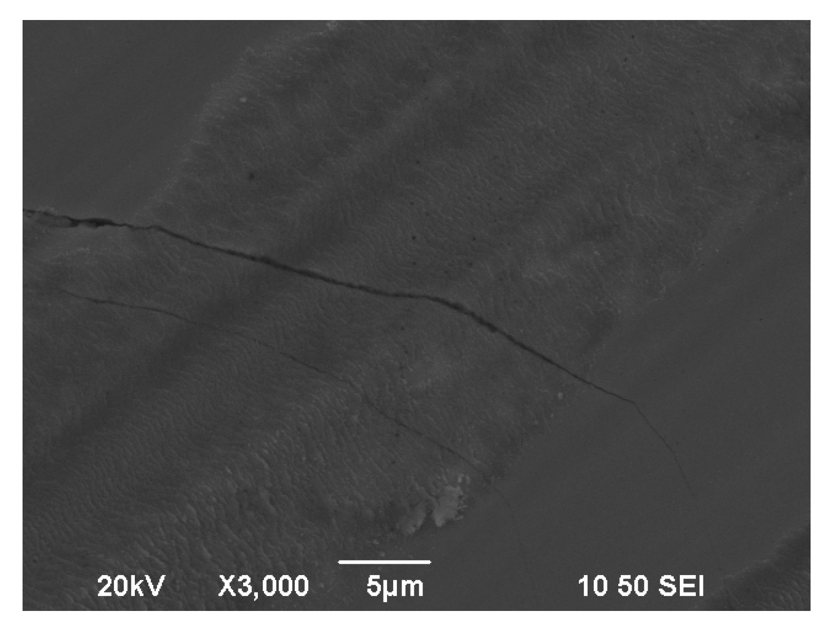
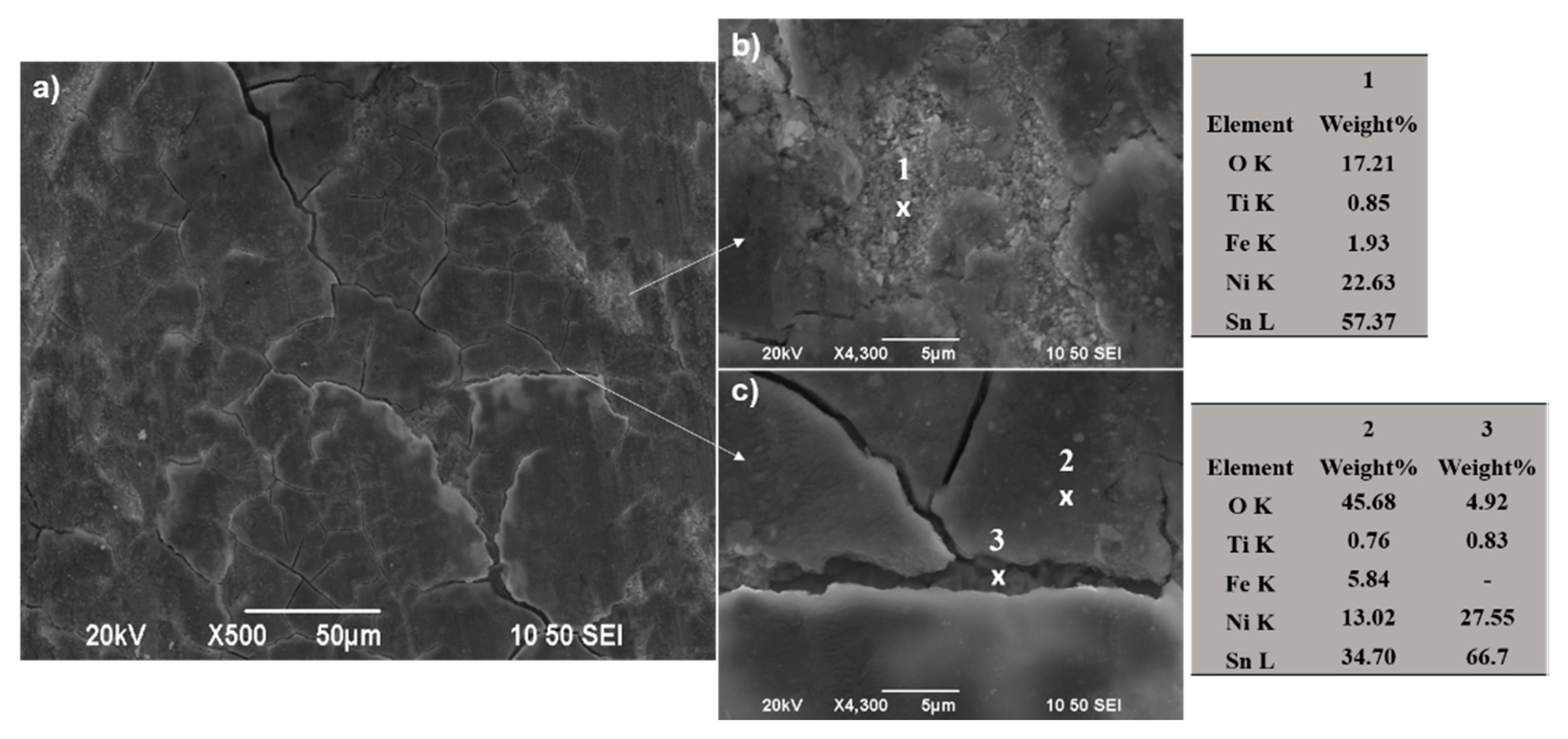
3.2.2. Morphology and Structure of Sn–Ni/doped-TiO2 Composite Coatings

The surface morphology of the deposits with immobilized TiO2 particles is characterized as a cauliflower-type structure in which the typical globular features are distributed across the samples’ surface as depicted in Figure 8. These features are spherical with different sizes along the surface, inducing a matt finishing to the coating compared to the shiny, mirror-like finishing pure ones, from a visual point of view. Images with low magnification demonstrate that the spherical structures are spread homogenously through the coatings’ surface (see Figure 8a,c).
The effect of using a different type of particulates on the surface roughness and brightness is summarized in Table 3. The data demonstrate clearly that all composites fabricated under different current density values and types of used powders exhibit higher roughness values in comparison to the pure coatings.
The Sn–Ni/N,S-TiO2 composite coatings produced under high current density values (Table 3, Sample C) are characterized by less agglomerated globular structures on the surface of the sample (see Figure 8d), exhibit lower roughness (see Table 3) associated with lower co-deposition amount of particles in the alloy matrix (see Table 3) compared to pure ones (Figure 4), as well as to composites produced under low current density values (Table 3, Sample B) (Figure 8b).
Sn–Ni/Kronos TiO2 composites exhibit medium roughness values while the Sn–Ni/N,S-TiO2 coatings present the highest roughness values among all composite coatings. This finding is also verified when comparing the corresponding FE-SEM images of the surface morphology (see Figure 8). It is noteworthy that composites produced under the same current density (3 A·dm−2) exhibiting the same co-deposition percentage of particles (see Table 3, Samples C and E) are characterized by more microcrystalline surface in case of using Kronos particles (Figure 8e, Sample E), accompanied by grain reduction of alloy matrix as demonstrated by data of XRD (see Table 3). It seems that Kronos particles are more uniformly dispersed through the alloy matrix (as evident also in Figure 8f), the presence of which might be associated with new nucleation sites for alloy-growth inducing finally low surface roughness. However, nano-crystalline alloy structure could be also achieved by applying low current density values in presence of enhanced embedded N,S-TiO2 particles in the matrix which consequently provide either new nucleation sites or overall perturb the alloy crystal growth [14,17].
X-ray diagrams of the composite coatings are depicted in Figure 9. The X-ray data of two types of used powders are also included. The diffraction patterns of the composite coatings demonstrate that the incorporation of the different types of doped-TiO2 particles in the alloy metal matrix modifies significantly the crystal structure compared to the pure coatings (see Figure 3). The main diffraction peak of the composite coatings is detected at 2θ ≈ 43.6° which is also present in the corresponding diagrams of pure ones. Additionally, a new peak at 2θ ≈ 30° is present in all types of composite coatings and both observed peaks are attributed to the metastable phase NiSn [27]. It seems that the presence of co-deposited TiO2 particles in the alloy is accompanied by the appearance of the low intensity diffraction peak of NiSn metastable phase composite coatings at 30° assigned to the (101) diffraction plane of the metastable SnNi phase (JCPDS no. 06-0414) [29]. Additionally, the intensity of Sn diffraction peak at 2θ ≈ 80° is enhanced in case of composite Sn–Ni/Kronos TiO2 (produced at J = 3 A·dm−2) deposits compared to Sn–Ni/N,S-TiO2 coatings (produced at J = 1 A·dm−2) since increasing values of applied current density favor an increase in Sn content as shown in data of Figure 3 and Figure 5b.
It is worth mentioning that the X-ray diffraction patterns revealed that the main diffractions peaks of the used doped-TiO2 powders do not appear in the case of the corresponding composites. This is in agreement with results reported in composite Ni/TiO2 matrix electrodeposits fabricated under direct current conditions and various values of TiO2 loadings and applied current density values [14].
In Figure 10, the XRD patterns of pure and composite coatings which were recorded by slow scanning rate around the high intensity diffraction peak of 2θ ≈ 43.6° of the metastable phase NiSn demonstrate a clear shift of the position of the peak to lower theta values, which in turn indicates alteration of the lattice characteristics of the binary alloy matrix. By applying Scherrer’s formula at this peak, the average grain size was estimated as presented in Table 3. The XRD data analysis reveals that all types of coatings (pure and composites) could be characterized as nano-crystalline. The pure Sn–Ni coatings exhibit an average crystallite size at values close to approximately ~22 nm. On the other hand, all composite coatings are characterized by higher average grain size values compared to the pure ones.
It should be mentioned that as the N,S-TiO2 loading in the bath increases under constant current density, the TiO2 co-deposition percentage in the coating is increased as well (see also Figure 6), while the mean grain size of the crystallites does not seem to be altered significantly (Table 3, Sample A and B). In the case of the composite coatings embedded with commercial TiO2 Kronos particles, similar results are deduced in which the average grain size values of composites were estimated in the range of ~45–47 nm, revealing almost double values of the corresponding reported ones in case of pure coatings.
However, the mean grain size is increased with increasing values of applied current density even though a sufficient amount of immobilized doped-TiO2 particles are present in the alloy (Table 3, Sample C). This behavior is consistent with the results presented in studies related to the electrodeposition of alumina in nickel matrix [30] and Ni-based matrix- TiO2 particles [7,14].
Overall, the embedding of doped-TiO2 particles yields in a perturbation of the crystalline structure of the SnNi metastable phase as indicated by the presence of additional peaks and the observed shift in the position of the main diffraction peak. It seems that the competition between nucleation and crystal growth leads to grain enlargement in the presence of TiO2 particles compared to pure coatings. However, no significant alteration in size is observed in the case of enhanced co-deposition percentage of doped-TiO2 particles in the alloy-matrix but grain growth is promoted under applied high current density values. According to previous studies in electrodeposited pure Sn–Ni coatings examined by XRD and TEM techniques, a significant grain growth was observed with increasing Sn content in the coating [27]. Therefore, it is quite possible that the observed grain growth compared to that of pure coatings is associated with increased Sn content in the composites. Future studies including high resolution TEM analysis comparing pure and composite coatings could enlighten the codeposition mechanism of doped-TiO2 particles in alloy matrix and justify systematically the grain growth of the alloy crystallites in presence of TiO2 reinforcement.

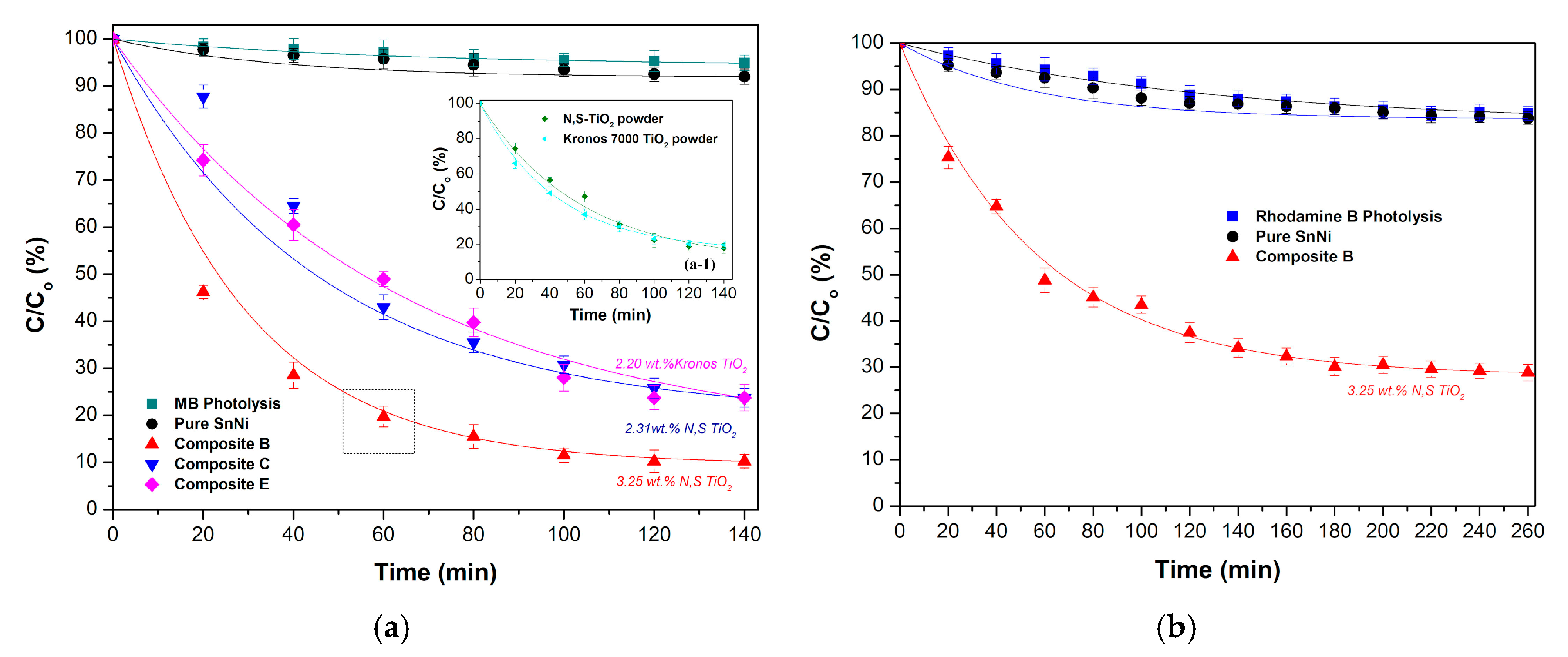
3.3. Photo-Catalytic Properties of Coatings

The photocatalytic performance of composite coatings with immobilized doped-TiO2 particles within Sn–Ni alloy matrix was conducted by studying the degradation of methylene blue and Rhodamine B under visible illumination.
Figure 11 demonstrates the degradation percentages of both dye solutions at various time intervals for the different types of composites, including the dye adsorption of the reference sample i.e., of pure Sn–Ni coating. The photolysis for MB and RhB is also included exhibiting a degradation percentage of the dye less than 10%, for both cases. The inset (a-1) in Figure 11a illustrates the degradation percentages of MB solutions in the case of the used powder N, S-TiO2, and commercial Kronos 7000 for comparison reasons. It is apparent that the photocatalytic behavior of both powders is quite similar, achieving a MB degradation 70% at 80 min, and at the longest period of 140 min, a corresponding value of 82.5% is accomplished.
As expected, pure Sn–Ni coating (Figure 11a,b) does not exhibit any significant photocatalytic activity, and the obtained small MB and RhB degradation values are rather close to those corresponding to the photolysis. However, an additional restricted absorbance is observed that could be related either to the activity of an oxide layer formed on the top surface of the alloy coating or to specified surface characteristics, such as the roughness of the pure coatings. In the case of the composite coatings, when comparing deposits with similar codeposition TiO2 doped percentage (2.2 wt.%–2.3 wt.%) both type of coatings (embedded Kronos 7000 and N,S-TiO2 particles in alloy matrix) exhibit similar photocatalytic performance achieving almost 80% degradation of the MB pollutant at 140 min visible illumination. However, with increasing incorporation percentage (3.25 wt.%) of N,S-TiO2 particles in the alloy (Sample B), an enhanced photo-degradation ~90% is observed when exposed to visible illumination for 140 min. It is noteworthy that this type of composite coating (Figure 11a) exhibits the best photocatalytic activity, as proven by the MB degradation percentage of 80% at 60 min of illumination compared to the corresponding powder (inset Figure 11a), where only 50% of the pollutant has been degraded. This enhanced photocatalytic action was also proven by using another type of organic pollutant, i.e., Rhodamine B, that exhibited a degradation percentage of ~70% under visible light irradiation for 160 min (Figure 11b). Therefore, the photocatalytic data imply that it is important to immobilize doped-TiO2 catalyst efficiently in an alloy metal matrix that could provide efficient separation of photogenerated electron-hole pairs in the TiO2 component resulting to enhanced photocatalytic performance, as proved in the case of Ni matrix composites and evidenced by the formation of co-clusters on the surface of the coatings [5,35].
As noted in Section 3.2.2, composite coatings with enhanced co-deposition of TiO2 particles are characterized by increasing roughness values (see Table 3), which could be associated with enhancement of active surface area for surface coverage realized by the pollutant and thus, favoring the photocatalytic behavior. The efficiency of the immobilized TiO2 catalyst in a metal matrix often changes with the hosting metal [5], the nature of the matrix, like crystalline orientation [7], as well as grain size or another semiconductor. Additionally, the role of the supporting matrix morphology and surface area is also crucial, as a significant improvement in photo-induced reaction rates and yields can result from the optimization of the aforementioned parameters [7,36]. The same behavior has also been detected in the case of doping the catalyst with a metal [3]. It is worth mentioning that for Ni matrix TiO2 based composites, a “site proximity” model has been proposed to account for the enhancement of photocatalytic activity in which the metal sites provide the adsorption function and the (adjacent) TiO2 sites serve to photo-convert the sequestered (and thus concentrated) pollutant molecules at the interface [5,35]. Overall, the data of this study have demonstrated that best photocatalytic behavior under visible irradiation was achieved for the composite coatings with the highest incorporation percentage of doped N,S-TiO2 powder (Sample B).

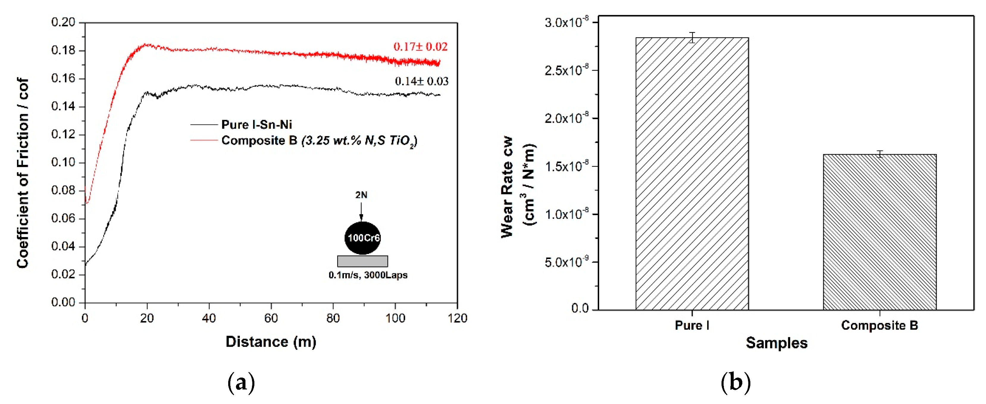
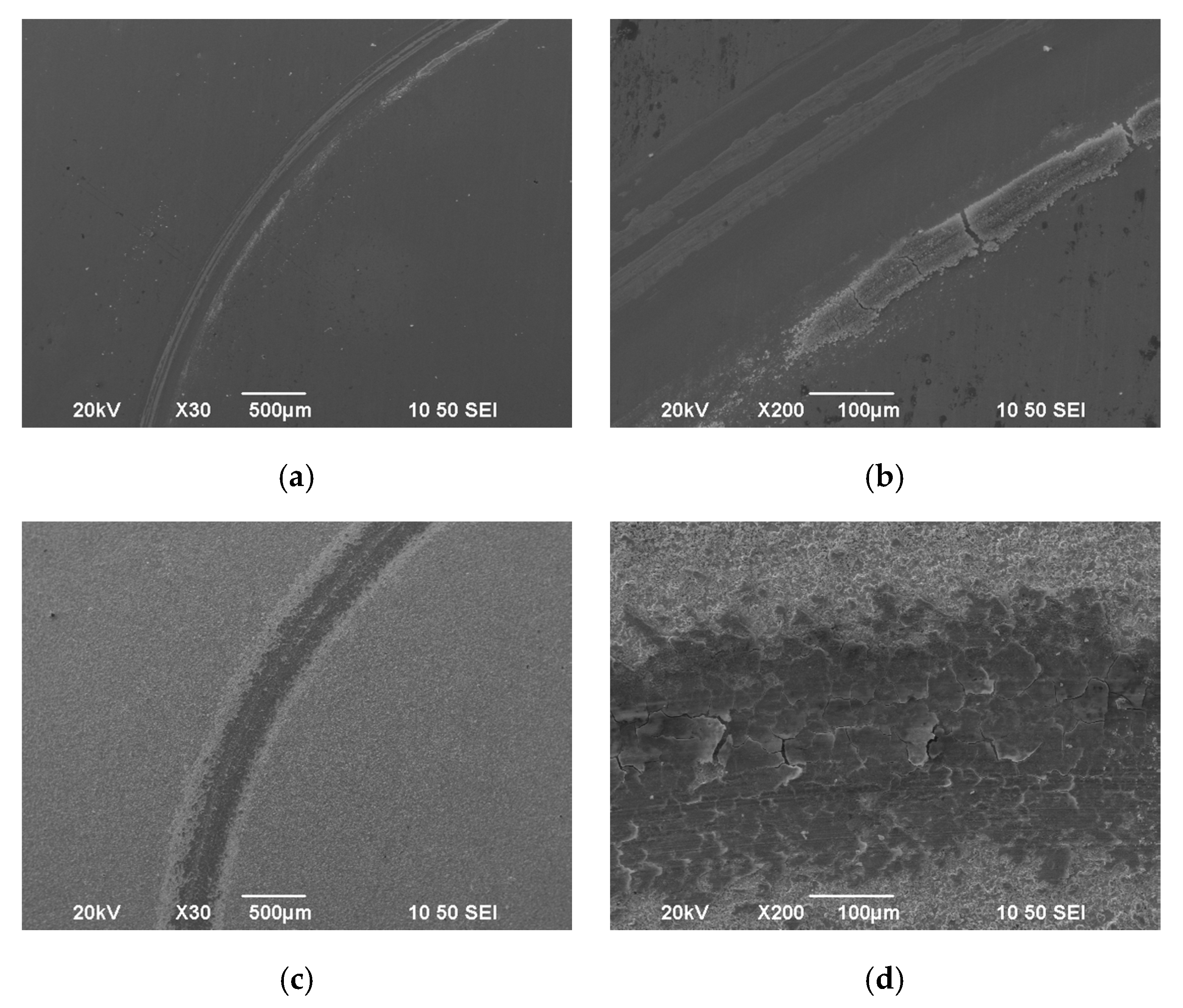
3.4. Nanoindentation Tests and Tribological Performance of Coatings

The mechanical properties such as elastic modulus and hardness were evaluated by nano-indentation tests performed on the surface for all the samples tested for their photocatalytic performance regarding pure (Sample I) and composite coatings (Samples B, C, and E) and the results are demonstrated in Table 4.
The pure Sn–Ni coating (Sample I) exhibits the highest hardness among all examined coatings achieving a value of 10.3 GPa in agreement with those reported by Georgiou et al. [29]. However, the incorporation of both types of TiO2 nanoparticles in the alloy metal matrix provokes a slight decrease in the hardness of the composite coatings reaching a value of ~8.9 GPa, which corresponds to a ~12%–14% reduction in hardness value compared to the pure coating. This inconsiderable decrease in hardness can be attributed to the modification of the alloy matrix evidenced by the increase of Sn content and the enlargement of the grain size as supported by the XRD data (see Section 3.2), as well as by increased roughness values of the composites as compared to pure ones (see Table 3). All the tested composite coatings, regardless of the electrodeposition parameters applied and the type of embedded TiO2 nanoparticles, demonstrated a significant grain growth that could lead to reduced hardness values as compared to those of pure one, following the Hall–Petch theory. It should be noticed that not only the weight percentage of the particles in the matrix but also their degree of dispersion, as well as their interface coherency with the matrix, plays crucial roles in the hardness values [37]. Therefore, it seems that for this kind of composites the embedded particles are not adequately distributed uniformly in the matrix accounting for effective blocking of the propagation of dislocations, and thus imposing a dispersion-hardening effect. Hence, an increased number of the particles are codeposited as aggregates resulting in a slight diminishing of the corresponding hardness values. It is worth mentioning that similar behavior was reported in embedded TiO2 particles within Cu–Sn–Zn [19] and Sn–Co [38] alloy matrix coatings, where an increased amount of TiO2 particles was accompanied by a slight decrease of hardness.
Despite the increase in the Sn content and the grain growth of the alloy matrix that takes place, the embedding of TiO2 nanoparticles exhibits a slight beneficial effect towards the elastic modulus compared to pure coating, which exhibits the lowest value of 145 GPa, in agreement with relative previous work [29]. All composites demonstrated values in the range of 157–165 GPa. It is known that during electrodeposition, several processes like adsorption and incorporation of additives, possible parasitic reactions resulting in impurity inclusions may affect the elevated residual stresses [39]. Moreover, the embedding of TiO2 nanoparticles in the nanocrystalline alloy metal matrix could be associated with a modification of residuals stresses, which can subsequently influence their tensile strength [40,41].
The tribological properties were measured for the composite coating Sn–Ni/N,S-TiO2 (Sample B) exhibiting the best photocatalytic performance, as well as the highest TiO2 incorporation percentage, among all type of composite coatings tested. For comparison reasons, pure coating Sn–Ni (Sample I) was also examined. Both samples were produced under direct current conditions applying the current density of J = 1 A·dm−2. The evolution of the dry sliding friction coefficient (cof = μ) was recorded as a function of the covered distance (m) (Figure 12a).
A running-in stage was detected within the first 700 cycles (20 m) for both types of coatings, followed by the steady-state of the tribotest. The mean values of the recorded cof ones during the whole test revealed that the composite coating exhibits a slightly higher cof value (i.e., μ = 0.17) as compared to the pure coating (μ = 0.14) Taking into consideration the comparable hardness values, the observed differences in the structural and compositional characteristics (grain size and TiO2 incorporation percentage) of the pure and composite coatings, reflect mainly on their evolution of friction coefficient. The morphology of typical wear tracks of pure and composite coatings is presented in Figure 13 and Figure 14.
In the case of pure SnNi coating, a debris layer is formed on both sides of the wear track (Figure 13a,b). EDS analysis near the debris layer (Figure 15, Spectrum 1) revealed high oxygen percentage wt.% verifying the oxide nature of the debris accompanied by the presence of Fe indicating also material transferred from the 100Cr6 ball during the sliding tests. In SEM micrographs (Figure 13), the formation of metal oxides resulted in a characteristic grey color of the wear track and light grey for formed debris near the track as depicted in Figure 15. Georgiou et al. [42] have demonstrated that Sn oxidizes preferentially to Ni in the temperature range of 20–400 °C forming a SnO2 oxide layer on Ni–Sn worn surfaces. Additionally, the wear scars of these pure Sn–Ni coatings exhibited brittle fracture cracks vertical to the direction of motion and scratches parallel to the same direction are distinguished (see Figure 14a and Figure 16), which are typical for abrasive wear. Similar fracture cracks were also reported by Antler at al [43]. However, no delamination under sliding wear tests was detected. Therefore, it seems that both abrasion and oxidation mechanisms could ascribe the wear of the pure Sn–Ni coatings under these specific tribological conditions.
In the case of composite SnNi/TiO2 coating (Sample B), the wear track demonstrates shallow scratches (see Figure 13c,d and Figure 14b) parallel to the direction of motion, revealing the existence of abrasive wear to a less extent compared to the pure one (Figure 14a). On both sides of the worn surface, homogeneously asperities were superimposed (see Figure 13c and Figure 14b) and wear debris adhered to the wear track surface forming several micro-crackings, which can be seen in detail in Figure 13d and Figure 17. Additionally, by taking a careful EDAX analysis on the wear track of the composite coating as shown in Figure 17 (spots 1, 2), extended areas with high oxygen content are apparent, indicating the formation of oxide wear debris, which is characteristic of the presence of oxidative wear process.
Moreover, qualitative analysis in the wear track revealed a considerable material transfer from the opponent ball to the composite (see analysis spot 2 of Figure 17) compared to that observed for pure Sn–Ni coating (see spot 1 of Figure 17) indicating that the composite exhibits enhanced resistance to dry sliding. Delamination of the debris layer is also detected (see Figure 17, spot 1) revealing material transferred from the ball during the sliding tests, as well as the formation of metal oxides. However, beneath the formation of micro-cracks considerably reduced oxygen content is recorded without any material transfer from the opponent ball (see Figure 17c, spot 3).
The wear data indicate that oxidation phenomena take place more extensively compared to pure coatings during sliding tests. The formation of oxides and preferably of SnO2 according to recent data [43] and the adhesion of this oxide film on the underlying coatings can affect either positively or negatively the contacting surfaces in the tribosystem, and thus the wear performance of the coatings.
The evaluation of volumetric wear rate cw of pure SnNi (Sample I) and composite SnNi/N,S-TiO2 (Sample B) coatings (Figure 12b), demonstrated that the presence of the N,S-TiO2 nanoparticles increased the wear resistance of the composite coating compared to the pure SnNi one.
The hard reinforcement of doped N,S-TiO2 particles in the matrix may reduce the direct contact between Sn–Ni matrix and the abrasive surface, resulting in reduced wear rate compared to that of pure coatings. Overall, the wear behavior of pure and composite coatings under dry sliding conditions against steel ball revealed that abrasion, adhesion and oxidation phenomena take place and the best tribological performance is achieved in the case of the composite SnNi/N,S-TiO2, which also demonstrated the best photocatalytic behavior under visible irradiation and almost preserved the mechanical properties of those of pure coatings.

4. Conclusions

Direct current electrodeposition was applied to immobilize doped-TiO2 particles into tin-nickel alloy metal matrix to produce indoor photocatalytic coatings. The composite Sn–Ni/TiO2 nano-coatings were produced by embedding two different types of TiO2 particulates within the alloy matrix, doped carbon-based particles and doped N,S-TiO2 particle both photocatalytic active under visible irradiation. The effect of loading and type of particles in the electrolytic bath as well as, the applied current density on the structural characteristics (surface morphology, crystallographic orientation) and the photocatalytic performance of the composite coatings have been reported.
Pure Sn–Ni coatings with approximately 65 wt.% tin content were produced and characterized by the presence of the metastable phase NiSn, exhibiting a low roughness and nano-crystalline structure. The surface morphology of pure Sn–Ni consisted of spherical grains with various sizes along the surface.
Regardless of the type of doped particles TiO2, increasing values of applied current density from 1 to 5 A·dm−2 resulted in the reduction of the co-deposition percentage of TiO2 particles in the coating and increase of Tin content into the alloy matrix. Overall data demonstrated that the optimum values for achieving high codeposition rates of particles for both kinds of powders were defined at low current density values (1 A·dm−2) and 30 g·L−1 under direct current conditions. The highest co-deposition percentage of 3.25 wt.% was detected in the case of embedding N,S-TiO2 particles. The surface morphology of composites Sn–Ni/TiO2 was characterized as a cauliflower-type of structure resulting in increasing roughness values compared to pure coatings. The X-ray diffraction analysis of the composite coatings showed that the incorporation of the different types of TiO2 particles in the alloy-metal matrix modified significantly the nano-crystalline structure in comparison to the pure coatings.
Among all tested composites, the best photocatalytic behavior under visible irradiation was reported for the composite coatings exhibiting the highest incorporation percentage of doped N,S-TiO2 powder (3.25 wt.%). Nano-indentation measurements disclosed that these composite coatings almost preserve the microhardness and Young modulus values that the pure alloy exhibited. Overall, the wear behavior of pure and composite coatings under dry sliding conditions against steel ball revealed that abrasion, adhesion, and extensive oxidation phenomena took place on the surface of the worn surfaces of the coatings. However, enhanced wear resistance was revealed for the case of the composite Sn–Ni/N,S doped TiO2 exhibiting the best photocatalytic activity under visible irradiation and thus, brings into light promising self-cleaning surfaces on every day touching objects like knobs, handles, etc. Future antimicrobial studies could also emerge the function of this type of coatings in a wide range of photo-induced applications.

Author Contributions

Conceptualization, E.R., C.Z., and E.A.P.; Investigation, E.R.; Methodology, E.R., S.S., C.Z., D.S.T., P.L., and E.A.P.; Formal Analysis, S.S., C.Z., and D.S.T.; Validation, S.S., S.K., and P.L.; Resources, C.Z. and S.K.; Writing—Original Draft, E.R.; Supervision, E.A.P., Project Administration P.L. and E.A.P.; Writing—Review and Editing, E.R. and E.A.P. All authors have read and agreed to the published version of the manuscript.

Funding

This research was funded by the European Union’s FP7–SME 2012-1 (Research for SMEs) program, SELFCLEAN “Novel Self-cleaning, anti-bacterial coatings, preventing disease transmission on every day touched surfaces”, under grant agreement No 314988.

Acknowledgments

The authors would like to thank Emeritus Jean-Pierre Celis (KU Leuven, Belgium) and Mustafa Ürgen (ITU-Istanbul, Turkey) for discussions and training courses held on this topic within the scope of the EU funded COST MP1407 ‘EMINDS’ network.

Conflicts of Interest

The authors declare no conflict of interest.

References

  1. Wang, Y.; He, Y.; Lai, Q.; Fan, M. Review of the progress in preparing nano TiO2 an important environmental engineering material. J. Environ. Sci. 2014, 26, 2139–2177. [Google Scholar] [CrossRef] [PubMed]
  2. Katoueizadeh, E.; Zebarjad, S.M.; Janghorban, K. Investigation of mechanical characteristics of functionalized cotton textiles by N-doped TiO2 nanoparticles. Mater. Chem. Phys. 2018, 218, 239–245. [Google Scholar] [CrossRef]
  3. Pelaez, M.; Nolan, N.T.; Pillai, S.C.; Seery, M.K.; Falaras, P.; Kontos, A.G.; Dunlop, P.S.M.; Hamilton, J.W.J.; Byrne, J.A.; O’Shea, K.; et al. A review on the visible light active titanium dioxide photocatalysts for environmental applications. Appl. Catal. B Environ. 2012, 125, 331–349. [Google Scholar] [CrossRef] [Green Version]
  4. Banerjee, S.; Pillai, S.C.; Falaras, P.; O’shea, K.E.; Byrne, J.A.; Dionysiou, D.D. New insights into the mechanism of visible light photocatalysis. J. Phys. Chem. Lett. 2014, 5, 2543–2554. [Google Scholar] [CrossRef] [Green Version]
  5. Tacconi, N.R.; Carmona, J.; Rajeshwar, K. Surface morphology/composition and photoelectrochemical behavior of metal-semiconductor composite films. Langmuir 2000, 16, 5665. [Google Scholar] [CrossRef]
  6. Thiemig, D.; Bund, A. Characterization of electrodeposited Ni-TiO2 nanocomposite coatings. Surf. Coat. Technol. 2008, 202, 2976. [Google Scholar] [CrossRef]
  7. Spanou, S.; Kontos, A.I.; Siokou, A.; Kontos, A.G.; Vaenas, N.; Falaras, P.; Pavlatou, E.A. Self cleaning behaviour of Ni/Nano-TiO2 metal matrix composites. Electrochim. Acta 2013, 105, 324–332. [Google Scholar] [CrossRef]
  8. Wan, C.; Zhang, L.; Liu, X. Corrosion assessment of Sn–Ni alloy coatings using neutral salt spray tests and electrochemical methods. Int. J. Electrochem. Sci. 2020, 15, 26–38. [Google Scholar] [CrossRef]
  9. Wan, C.; Liu, X.; Ye, J. Tailorable deposition of Sn–Ni alloy from a pyrophosphate bath with an adjustable Sn:Ni molar ratio. Surf. Coatings Technol. 2019, 369, 244–251. [Google Scholar] [CrossRef]
  10. Lačnjevac, U.; Jović, B.M.; Jović, V.D. Electrodeposition of Ni, Sn and Ni–Sn alloy coatings from pyrophosphate-glycine bath. J. Electrochem. Soc. 2012, 159, D310. [Google Scholar] [CrossRef]
  11. Jalota, S.K. Tin–nickel alloy plating. Met. Finish. 1999, 97, 319–322. [Google Scholar] [CrossRef]
  12. Kuznetsov, B.V.; Vorobyova, T.N.; Glibin, V.P. A Comparative study of Tin-nickel alloys obtained by electroplating and casting. Met. Finish. 2013, 111, 38–42. [Google Scholar] [CrossRef]
  13. Lačnjevac, U.Č.; Jović, V.D.; Jović, B.M. Electrodeposition and characterization of Ni–Sn alloy coatings as cathodematerial for hydrogen evolution reaction in alkaline solutions. ZAŠTITA Mater. 2011, 52, 153–158. [Google Scholar]
  14. Spanou, S.; Pavlatou, E.A.; Spyrellis, N. Ni/nano-TiO2 composite electrodeposits: Textural and structural modifications. Electrochem. Acta 2009, 54, 2547–2555. [Google Scholar] [CrossRef]
  15. Torabinejad, V.; Aliofkhazraei, M.; Assareh, S.; Allahyarzadeh, M.H.; Rouhaghdam, A.S. Electrodeposition of Ni-Fe alloys, composites, and nano coatings—A review. J. Alloys Compd. 2017, 691, 841–859. [Google Scholar] [CrossRef]
  16. Spanou, S.; Pavlatou, E.A. Ni/nano-TiO2 composite electrocoatings: Correlation between structural characteristics microhardness and wear resistance. Z. Phys. Chem. 2011, 225, 31. [Google Scholar] [CrossRef]
  17. Lampke, T.; Leopold, A.; Dietrich, D.; Alisch, G.; Wielage, B. Correlation between structure and corrosion behaviour of nickel dispersion coatings containing ceramic particles of different sizes. Surf. Coat. Technol. 2006, 201, 3510. [Google Scholar] [CrossRef]
  18. Krawiec, H.; Vignal, V.; Latkiewicz, M.; Herbst, F. Structure and corrosion behaviour of electrodeposited Co-Mo/TiO2 nano-composite coatings. Appl. Surf. Sci. 2018, 427, 1124–1134. [Google Scholar] [CrossRef]
  19. Gao, W.; Cao, D.; Jin, Y.; Zhou, X.; Cheng, G.; Wang, Y. Microstructure and properties of Cu-Sn-Zn-TiO2 nano-composite coatings on mild steel. Surf. Coat. Technol. 2018, 350, 801–806. [Google Scholar] [CrossRef] [Green Version]
  20. Yousefi, E.; Sharafi, S.; Irannejad, A. The structural, magnetic, and tribological properties of nanocrystalline Fe-Ni Permalloy and Fe-Ni-TiO2 composite coatings produced by pulse electro co-deposition. J. Alloys Compd. 2018, 753, 308–319. [Google Scholar] [CrossRef]
  21. Pyanko, A.V.; Makarova, I.V.; Kharitonov, D.S.; Makeeva, I.S.; Alisienok, O.A.; Chernik, A.A. Tin-nickel-titania composite coatings. Inorg. Mater. 2019, 55, 568–575. [Google Scholar] [CrossRef]
  22. Noophum, B.; Sikong, L.; Kooptanond, K. Photocatalytic properties of nitrogen-sulfur co-doped TiO2 films coated on glass fiber. Adv. Mater. Res. 2013, 781–784, 2237–2240. [Google Scholar] [CrossRef]
  23. Patterson, A.L. The scherrer formula for X-ray particle size determination. Phys. Rev. 1939, 56, 978–982. [Google Scholar] [CrossRef]
  24. Stichleutner, S.; Lak, G.B.; Kuzmann, E.; Chisholm, C.U.; El-Sharif, M.; Homonnay, Z.; Sziráki, L. Mössbauer and XRD study of pulse plated Sn-Fe, Sn-Ni and Sn-Ni-Fe electrodeposited alloys. Hyperfine Interact. 2014, 226, 15–25. [Google Scholar] [CrossRef]
  25. Spiridonov, B.A.; Berezina, N.N. Electroplating and structure of tin-nickel coatings. Prot. Met. 2004, 40, 85–88. [Google Scholar] [CrossRef]
  26. Paunovic, M.; Schlesinger, M. Fundamentals of Electrochemical Deposition; Willey-Interscience: Hoboken, NJ, USA, 2006; Volume 2, p. 205. [Google Scholar]
  27. Watanabe, T. Nano-Plating; Elsevier: Amsterdam, Netherlands, 2004; pp. 176–182, 630–640. [Google Scholar]
  28. Cavallotti, P.L.; Nobili, L.; Vicenzo, A. Phase structure of electrodeposited alloys. Electrochim. Acta 2005, 50, 4557–4565. [Google Scholar] [CrossRef]
  29. Georgiou, E.P.; Van der Donck, T.; Celis, J.P. Electrodeposition and structural characteristics of intermetallic nickel-Tin based coatings. Trans. Inst. Met. Finish. 2017, 95, 301–307. [Google Scholar] [CrossRef]
  30. Banovic, S.W. Characterization of single and discretely-stepped electro-coatings on nickel-alumina. J. Mater. Sci. 1999, 34, 3203–3211. [Google Scholar] [CrossRef]
  31. Niu, Z.; Cao, F.; Wang, W.; Zhang, Z.; Zhang, J.; Cao, C. Electrodeposition of Ni-SiC nanocomposite film. Trans. Nonferrous Met. Soc. China 2007, 17, 9–15. [Google Scholar] [CrossRef]
  32. Fransaer, J.; Celis, J.P.; Roos, J.R. Analysis of the electrolytic codeposition of non-brownian particles with metals. J. Electrochem. Soc. 1992, 139, 413. [Google Scholar] [CrossRef]
  33. Guglielm, N. Kinetics of deposition of inert pariicles from electrolytic baths. J. Electrochem. Soc. 1972, 119, 1009–1012. [Google Scholar] [CrossRef]
  34. Alizadeh, M.; Cheshmpish, A. Electrodeposition of Ni–Mo/Al2O3 nano-composite coatings at various deposition current densities. Appl. Surf. Sci. 2019, 466, 433–440. [Google Scholar] [CrossRef]
  35. Rajeshwar, K.; Tacconi, N.R.; Chenthamarakshan, C.R. Semiconductor-based composite materials: Preparation properties, and performance. Chem. Mater. 2001, 13, 2765. [Google Scholar] [CrossRef]
  36. Linsebigler, A.L.; Lu, G.; Yates, J.T. Photocatalysis on TiO2 surfaces: Principles, mechanisms and selected results. Chem. Rev. 1995, 95, 735. [Google Scholar] [CrossRef]
  37. Ahmadkhaniha, D.; Zanella, C. The effects of additives, particles load and current density on codeposition of SiC particles in NiP nanocomposite coatings. Coatings 2019, 9, 554. [Google Scholar] [CrossRef] [Green Version]
  38. Zhang, D.; Qaim, M.; Gao, W.; Zhang, W.; Owusu, A.B.; He, Z.; Wang, Y. Microstructure and properties of Tin-cobalt nanocomposite coatings reinforced by titanium dioxide nanoparticles. Mater. Res. Express 2019, 6, 126417. [Google Scholar] [CrossRef]
  39. Rouya, E.; Stafford, G.R.; Beauchamp, C.; Floro, J.A.; Kelly, R.G.; Reed, M.L.; Zangari, G. In situ stress measurements during electrodeposition of Au-Ni alloys. Electrochem. Solid-State Lett. 2010, 13, 87–90. [Google Scholar] [CrossRef]
  40. Baghal, S.M.L.; Amadeh, A.; Sohi, M.H. Investigation of mechanical properties and operative deformation mechanism in nano-crystalline Ni-Co/SiC electrodeposits. Mater. Sci. Eng. A 2012, 542, 104–112. [Google Scholar] [CrossRef]
  41. Baghal, S.M.L.; Amadeh, A.; Sohi, M.H. Effect of nano-SiC incorporation on mechanical properties of micro and nano-structured Ni–Co electrodeposits. J. Nanosci. Nanotechnol. 2013, 13, 1590–1593. [Google Scholar] [CrossRef]
  42. Georgiou, E.P.; Van der Donck, T.; Peeters, M.; Drees, D.; Celis, J.P. Proposed method to examine the effect of cycling temperatures on friction illustrated with intermetallic Ni-Sn coatings sliding against corundum. Wear 2016, 368–369, 453–460. [Google Scholar] [CrossRef]
  43. Antler, M.; Drozdowicz, M.H. The corrosion resistance of worn Tin-nickel and gold-coated Tin-nickel alloy electrodeposits. J. Electrochem. Soc. 1977, 124, 1069–1075. [Google Scholar] [CrossRef]
Figure 1. FE-SEM micrographs of (a), (b) Kronos vlp 7000 commercial powder, (c,d) N,S-TiO2 lab-made powder.
Coatings 10 00775 g001
Figure 2. X-ray diffraction patterns of doped (a) Kronos vlp 7000 and (b), N,S-TiO2 powders.
Coatings 10 00775 g002
Figure 3. X-Ray diffraction patterns of pure Sn–Ni coatings produced under direct current (DC) conditions and various applied current density values.
Coatings 10 00775 g003
Figure 4. FE-SEM surface micrographs of pure Sn–Ni coating produced under direct current conditions at J = 1 A·dm−2 (a) magnification ×2500, (b) magnification ×5000.
Coatings 10 00775 g004
Figure 5. (a) Weight percentage of N,S-TiO2 particles, immobilized within the alloy matrix at 30 g·L−1 TiO2 loading and (b) weight percentage of Sn content in the composite coating, as a function of current density values.
Coatings 10 00775 g005
Figure 6. Variation of the weight percentage of N,S-TiO2 particles embedded within the alloy matrix as a function of loading of TiO2 particles in the bath (10, 20, and 30 g·L−1) for various current density values.
Coatings 10 00775 g006
Figure 7. Weight percentage of commercial Kronos and N,S-TiO2 particles, immobilized within the alloy matrix at 30 g·L−1 TiO2 loadings as a function of applied current density values.
Coatings 10 00775 g007
Figure 8. HRFE-SEM surface micrographs of Sn–Ni/TiO2 composite coatings produced from a bath containing 30 g·L−1: (a,b) N,S-TiO2 particles in the bath and applied J = 1 A·dm−2, (c,d) N,S-TiO2 particles and J = 3 A·dm−2, and (e,f) Kronos 7000 TiO2 particles and J = 3 A·dm−2.
Coatings 10 00775 g008
Figure 9. X-ray diffraction patterns of composites: (a) Sn–Ni/N,S-TiO2 produced under J = 1 A·dm−2 at 20 and 30 g·L−1 TiO2 and (b) Sn–Ni/Kronos 7000 TiO2 deposits produced under J = 3 A·dm−2 at 20 and 30 g·L−1 TiO2 loading.
Coatings 10 00775 g009
Figure 10. Representative XRD patterns of pure and composite deposits focused at 2θ ≈ 43.6°.
Coatings 10 00775 g010
Figure 11. Degradation curves of (a) MB and (b) RhB as a function of time under visible light irradiation for pure and composite coatings Sn–Ni/doped TiO2. The inset (a-1) in Figure 11a depicts the degradation of MB for the two types of doped-TiO2 powders. In both diagrams the photolysis of (a) MB and (b) RhB is also included. Lines present exponential decay fitting curves.
Coatings 10 00775 g011
Figure 12. (a) Evolution of friction coefficient for pure SnNi (sample I) and composite SnNi/N,S-TiO2 coating (Sample B) sliding against 100Cr6 ball (d = 6 mm) and (b) Volumetric wear factor values of pure SnNi (Sample I) and composite SnNi/co-doped N,S-TiO2 (Sample B) coatings after sliding against 100Cr6 ball (d = 6 mm).
Coatings 10 00775 g012
Figure 13. SEM surface micrographs of wear track of (a,b) pure SnNi coating (Sample I), (c,d) composite coating Sn–Ni/N,S-TiO2 (Sample B).
Coatings 10 00775 g013
Figure 14. 3D and corresponding 2D plots of the wear tracks of (a) pure SnNi (Sample I) and (b) composite Sn–Ni/N,S TiO2 (Sample B).
Coatings 10 00775 g014
Figure 15. (a) SEM surface micrograph of wear debris of the pure SnNi coating-Sample I. and (b) EDS spectrum and analysis at grey-lighted spot 1.
Coatings 10 00775 g015
Figure 16. SEM micrograph inside the wear track of the pure SnNi coating-Sample I (magnification of area shown in Figure 13b.
Coatings 10 00775 g016
Figure 17. (a) Representative SEM surface micrograph inside the wear track of composite SnNi/co-doped N,S-TiO2 electrodeposit (Sample B). (b,c) Corresponding SEM surface micrograph at higher magnifications and corresponding spot EDS analysis: Spectrum 1 in image (b) and Spectrum 2, 3 in image (c).
Coatings 10 00775 g017
Table 1. Overview of the electrodeposition parameters for the preparation of pure Sn–Ni coatings and Sn–Ni composite coatings reinforced with different types of doped TiO2 particles.
Electrolyte CompositionElectrodeposition ConditionsType of PowderPowder Loading
NiCl2·6H2OT: 70 ± 1 (°C)N,S-TiO2
(d = 10 nm)
10, 20, 30 g·L−1
SnCl2 AnhydrouspH: 4.2–4.4Kronos TiO2
(d = 11 nm)
20, 30 g·L−1
Additive: containing fluorideAgitation: Pumping--
Galvaloy NS11 commercial bathCurrent density J: 1–5 (A·dm−2)--
Table 2. Experimental conditions for the tribological study of composite Sn–Ni/doped-TiO2 coatings.
Tribological ParametersExperimental Conditions
Load2 Ν
Ball100Cr6 (d = 6 mm)
Sliding cycles3000 Laps
Ball’s Linear velocity0.1 m/s
Ambient conditionsT = 25 °C, Humidity: 42–50%
Table 3. TiO2 incorporation (wt.%), average grain size (nm), and roughness (μm) values of pure Sn–Ni and composite Sn–Ni/doped-TiO2 coatings as deduced be EDAX, XRD, and Profilometry measurements.
SampleType of PowderPowder Loading (g·L−1)Current Density (A·dm−2)TiO2 Incorporation (wt.%) Average Grain Size (nm)Roughness Ra (μm)
Ι-01-220.027 ± 0.01
ΙΙ-03-210.015 ± 0.001
AN,S-TiO22011.78 ± 0.13481.334 ± 0.195
ΒN,S-TiO23013.25 ± 0.22551.381 ± 0.127
CN,S-TiO23032.31 ± 0.28740.999 ± 0.124
DKronos2031.71 ± 0.38480.382 ± 0.002
EKronos3032.2 ± 0.22450.639 ± 0.063
Table 4. Hardness and elastic modulus values of electrodeposited pure Sn–Ni (I) and Sn–Ni/TiO2 composite coatings (B,C,E) 1.
Sample NameΙ (pure)BCE
Hardness (GPa)10.3 ± 0.28.9 ± 0.49.1 ± 0.39.0 ± 0.3
Elastic Modulus (GPa)145 ± 18162 ± 17158 ± 13157 ± 13
1 The samples name follows the same notation used in Table 3.

