Abstract
To solve the problem of contamination flashover of a catenary insulator in an electrified railway, the collision mechanism and deposition characteristics of contamination particles on the insulator surface should be studied to ensure the safe operation of traction power supply systems. This research used horizontal and oblique cantilever insulators as objects, and established the collision model between particles and insulator surface under different arrangements. The deposition conditions of particles on the insulator surface were obtained, and the simulation model of insulator contamination accumulation was established by using the Euler two-phase flow. The difference of contamination deposition characteristics between horizontal and oblique cantilever insulators was analyzed with the volume fraction of contamination particles as the characterization parameter. By comparing the cantilever insulator with the positive feeder insulator, this study analyzed the influence of shed structure on the contamination deposition characteristics. Results show that the installation method of an insulator has an impact on the contamination deposition on the insulator surface. When particle size and wind velocity are fixed, the degree of contamination accumulation on the surface of the oblique cantilever insulator is constantly higher than that of the horizontal cantilever insulator. The insulator shed structure also has a certain effect on the contamination deposition on the insulator surface. For the cantilever insulator, the degree of contamination accumulation of the windward side is higher than that of the leeward side. However, for the positive feeder insulator, the degree of contamination accumulation of the windward side is consistently less than that of the leeward side. Measures to deal with contamination flashover of catenary insulator are proposed.
1. Introduction
An electrified railway catenary is a special high-voltage transmission line installed above rails and transmits electric energy to electric locomotives or motor train units by making contact with pantographs [1]. Catenary insulators are insulation equipment of traction power supply systems that mainly serve as mechanical support and electrical insulation [2]. Insulators are exposed to the atmosphere at all times to enable the easy deposition of contamination particles in the air on the insulator surface with the airflow, and the contamination contains a large amount of soluble substances. In humid environments such as those affected by rain, snow, and fog, they easily form a high conductivity dielectric layer [3,4]; hence, the increase in the insulator partial leakage current leads to a decline in insulation performance, thereby easily generating arc and even flashover [5,6,7,8]. Contamination deposition on the insulator surface is the fundamental factor inducing contamination flashover. Therefore, the collision mechanism and deposition characteristics of particles on the insulator surface should be studied for the insulation design of catenary and the formulation of anti-contamination flashover measures [9,10].
Many studies have been conducted on collision theory and the contamination deposition characteristics of particles on an insulator surface. Li et al. established the collision model between particles and insulator surface, analyzed the collision and adsorption movement of particles on the insulator surface, formulated the adsorption criterion between particles and insulator surface, and considered the corresponding effects of particle size, wind velocity, and humidity. He believed that the smaller the particle size, the higher the humidity, and the higher the wind velocity, the easier the particles are to be adsorbed [11]. Horenstein et al. studied the collision of charged insulator particles through experiments and theories. We obtained the relationship between the influence of wind force on the particle trajectory and the particle size, and proposed a model for quantitative prediction of the DC insulator contamination on transmission lines [12]. Hernandez et al. conducted the contamination test on the surface of the suspension insulator. The study found that the contamination accumulation on the insulator surface is serious when the shed structure is complex and many ribs exist on the lower surface. The structure of the insulator shed with less contamination accumulation on the insulator surface is simple, and the shed surface is smooth [13]. Jiang et al. regarded the insulator surface as an infinitely large flat plate, and established a collision model between the particles and insulator surface. The deposition conditions of the particles are obtained from the perspective of torque balance that consider the rolling of particles on the insulator surface. When the adsorption torque of the particles is higher than the sum of the frictional stress, drag stress, and elastic moment of the particles, the particles will be deposited on the insulator surface. Therefore, particle size is the critical value for deposition when it is 25 μm. If the particle size is below 25 μm, then the particles are deposited on the insulator surface [14]. Lv et al. considered the surface energy of the insulator surface, regarded the insulator as an infinitely large flat plate, and established a collision model between the particle and insulator surface from a three-dimensional perspective. The deposition conditions of particles are obtained according to their force balance. If the kinetic energy of all forces acting on the particles is higher than the energy of the particles before collision on the insulator surface, then the particles are eventually deposited on the insulator surface [15,16]. In the preceding research, the main object was the insulators in the power system environment and the arrangement of the insulators was vertical installation, so the application of the results is limited. To date, there is still a lack of research on the contamination deposition of an insulator in a catenary environment and the collision theory of particles on the insulator surface for the arrangement of the insulator.
In summary, the research object of this study was the catenary insulators of an electrified railway, which mainly include cantilever insulators installed horizontally and obliquely and positive feeder insulators. First, the collision model between particles and insulators with different installation methods was established, and the deposition conditions of particles and insulator surface were obtained. Second, fluent fluid software was used to establish a simulation model under a wind environment, the contamination deposition distribution of insulator surface was analyzed, and the differences of the contamination deposition characteristics on the insulator surface of the horizontal and oblique cantilever insulators were studied. Finally, the cantilever and positive feeder insulators with different shed structures were compared to study the effects of shed structure on the contamination deposition characteristics. The research can further improve the existing contamination deposition mechanism of insulators, and the results have certain guiding significance for the design, operation, and maintenance of the external insulation of the catenary [17]. Additionally, the maintenance cycle can be formulated according to the distribution of the contamination on the insulator surface to avoid flashover.
2. Theory of Particle Collision and Deposition on Insulator Surface
Various installation methods are used for catenary insulators including cantilever insulators installed horizontally and obliquely, and positive feeder insulator strings installed vertically. Figure 1 shows the site chart of electrified railway catenary insulators. The particles are infinitely small relative to the insulator, and the shed occupies most of the insulator area, so the insulator is considered as an infinite flat plate when establishing the collision model. As the insulator sheds are about perpendicular to the central axis of the insulator, in the preceding research, the insulator arranged vertically was often considered as a horizontal infinite flat plate [18]. However, the installation methods of catenary cantilever insulators are unique, hence, the research should consider the installation method of the insulator.
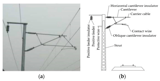
Figure 1.
Insulators of the electrified railway catenary: (a) insulator in the working state; (b) catenary structure chart.
This study assumes that the particle shape is spherical. For horizontally installed insulators, the surface of the insulator sheds was regarded as an infinitely large plate placed vertically when establishing a collision deposition model. For the same reason, the inclination angle for an insulator installed obliquely was assumed to be , and the insulator was regarded as an infinitely large flat plate with an inclination angle of . Figure 2 illustrates the collision model between the particles and insulator surface.
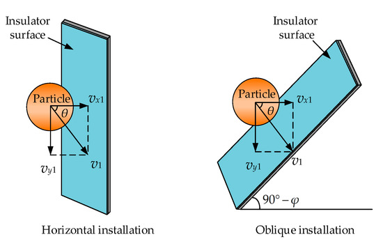
Figure 2.
Collision model between the particles and insulator surface.
The assumption was that the particles collide with the insulator surface at the horizontal and vertical velocities of vx1 and vy1, respectively, and assumed that the particles were round spheres, and adopted a hard ball model (i.e., particles do not deform when they collide). This study took a horizontally installed insulator as an example to analyze the collision deposition process between the particles and insulator surface.
The collision deposition process of the particles and insulator surface can be divided into four stages: injection, collision, recovery deformation, and ejection. When the cantilever insulator is installed horizontally, the insulator can be assumed as an infinitely large flat plate with the particle size relative to the insulator surface. Figure 3 shows the schematic of the collision deposition of the particles and insulator surface.
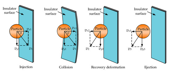
Figure 3.
Schematic of the particle collision deposition.
Injection stage: The particles are injected on the insulator surface at a horizontal velocity vx1, vertical velocity vy1, and collision angle of θ.
Collision stage: The particles collide with the insulator surface in an inelastic manner. The horizontal velocity of the particles gradually decreases. When the elastic deformation on the insulator surface is the maximum, the normal velocity of the particles is 0.
Recovery deformation stage: When the horizontal velocity is 0, the particle receives the largest elastic force on the insulator surface. At this time, the particle moves in a horizontal direction. When the insulator wall is restored to deformation, the elastic force becomes 0, and the horizontal and vertical velocities of the particles are vx2 and vy2, respectively.
Ejection stage: The particles are ejected outward at a velocity v2 and are bound by adhesion. If the particles can overcome the adhesion of the insulator surface, then they will bounce back in the air. However, if the particles cannot overcome the adhesion of the insulator surface, then they will be deposited on the insulator surface.
After the particles are injected on the insulator surface at the horizontal and vertical velocities of vx1 and vy1, respectively, then the particles are subjected to gravity, friction, and gas drag in the vertical direction, and the adhesion and elastic force of the insulator surface in the horizontal direction.
Some of the particles will adhere to the surface of the insulator when it comes into contact with the insulator surface. The adhesion force mainly includes the Van der Waals, electrostatic, and capillary forces. The Van der Waals force action begins to appear only when the distance between the particle and insulator surface is below 100 nm and increases as the distance decreases. This action is the main component of adhesion. The electrostatic force is due to the potential difference between the particles and plate, and other factors dominate after adhesion occurs. For the capillary force, the particles and insulator surface will form a liquid bridge after the relative humidity is above 50%, and the main influencing factor is related to air humidity. Figure 4 shows the schematic of the adhesion of particles to the surface of objects.
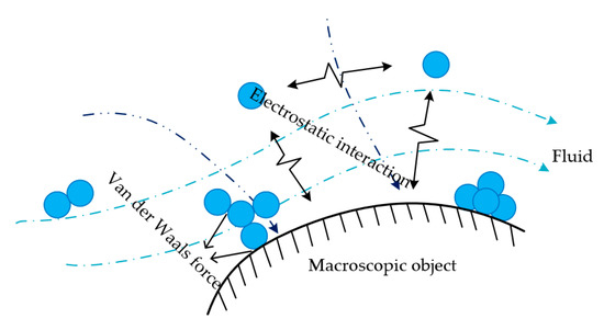
Figure 4.
Schematic of the surface adhesion.
The catenary insulator studied in this paper is designed to be in a dry and wind-sand environment, so the influence of capillary force on the insulator surface is ignored, and Van der Waals forces are the main factor of the adhesion force.
The calculation method of the Van der Waals force on particles is related to the different contact forms between the particles. The expression of the Van der Waals force between the ball and plate is shown in Equation (1) [19]:
where Fw is the Van der Waals force between the ball and plate, N; A is the Hamaker constant of the particle; H is the distance between the particle and plate, m; and R is the particle radius, μm.
During the collision between the particles and insulator surface, the particles squeeze the insulator surface to produce a small deformation, thereby producing an elastic force perpendicular to the wall. Equation (2) shows the elastic force Fa based on Hertz elastic theory [20]:
where Fa is the elastic force, N; S is the amount of deformation that occurs during collision; and k is the elastic deformation coefficient.
The deposition of particles on the insulator surface mainly depends on whether the particles can complete the ejection. If they can be ejected, then the particles will rebound into the air against the adhesion of the insulator surface. If the particles cannot overcome the adhesion of the insulator surface, then they will be deposited on the insulator surface. During the entire collision process, the energy loss suffered by the particles mainly includes the losses caused by the friction with the insulator surface in the vertical direction and the collision loss caused by the inelastic collision in the horizontal direction. These energy losses will reduce the ejection velocity of particles.
In the vertical direction, the sliding friction between the particles and insulator surface produces relative displacement. Eventually, the combined force of the particle’s gravity, friction, and aerodynamic resistance is 0.
During the ejection process, the particles are affected by Van der Waals forces in the horizontal direction and slow down. If the particles overcome the Van der Waals forces, then the ejection is completed; otherwise, the particles will be deposited on the insulator surface. The condition of the particle ejection is vx3 > 0.
When the particle adopts the hard ball model, which states that the collision process is instantaneous, and the velocity change before and after the collision depends on the recovery coefficient e [21]. Equation (3) shows the expression of the velocity relationship before and after particle collision:
where vx1 and vx1 are the velocities of the particles before and after collision, respectively, m/s; e is the recovery coefficient; σs is the ultimate yield; γ is the Young’s modulus; V is the velocity at which the particles collide with the insulator, m/s; m is the mass of the particles, kg.
When the particles are ejected in the horizontal direction, the Van der Waals forces must be overcome to complete the ejection. The work to overcome the Van der Waals force is Wa, and the calculation expression of Wa is shown in Equation (5):
where Wa is the work to overcome the Van der Waals force, J; hmax is the maximum distance where Van der Waals forces occur, m; and hmin is the minimum distance where the Van der Waals forces occur, m.
We obtain the following equation according to the preceding analysis and kinetic energy theorem:
From Equations (3) and (6), vx3 can be obtained as follows:
If the particle horizontal ejection velocity vx3 > 0, then the particles are ejected. If vx3 < 0, then the particles are deposited on the insulator surface.
According to the analysis of the horizontal installation method of the insulator, the horizontal and vertical velocities can be decomposed in the collision model of the oblique cantilever insulator to obtain the velocity vx3 of the particle ejection of the oblique installation method as in Equation (8).
Therefore, the particle ejection velocity vx3 on the surface of the insulator under different installation methods is shown in Equation (9):
According to the ejection velocity of the particles on the surface of the insulator, when the insulators are of the same material and the particle size is the same, the work done by the adhesion force and the particle mass are the same; the lower the ejection velocity, the easier the particles are deposited on the insulator surface. According to the analysis of the particle movement in the air, the velocity vx1 of the particles is an order of magnitude above vy1. Hence, . Compared with the horizontally and obliquely installed insulators, the particles are easier to deposit on the surface of the oblique cantilever insulator. That is, when the insulator structure is completely the same, the degree of contamination accumulation of the insulator surface installed obliquely at the same particle size and wind velocity is more serious than that of the insulator installed horizontally.
Different factors such as external electric field, particle shape, humidity, the insulator shed material, and so on, differently affect the collision and deposition characteristics of particles on the insulator surface. More influencing factors will be discussed in future research.
3. Mathematical Model of the Insulator Contamination
3.1. Euler Dual-Fluid Model
The movement of contamination particles carried by air is a typical gas–solid two-phase flow movement, which can be numerically simulated using the Euler two-fluid model. Euler’s double fluid aims to treat the air and particles as continuous fluids. The two fluids move according to their own laws and introduce volume fractions to describe the existence of each phase. The basic equation of Euler’s double fluid is as follows:
where and are the volume fraction of the air and particle phases, respectively. Each phase satisfies the mass conservation equation (i.e., fluid continuity equation) and momentum conservation equation.
The mass conservation equation of the air and particle phases (i.e., continuity equation) is as follows:
where is the density of the i-th phase, kg/m3; is the velocity of the i-th phase, m/s; and i = g represents the air phase and i = s represents the particle phase.
The momentum conservation equation of air phase and particle phase is as follows:
where p is the pressure, Pa; is the acceleration of gravity, m/s2; and are the stress tensors of the air and particle phases, respectively; and is the momentum exchange coefficient of the particle and air phases. The expression is as follows:
where CD is the drag coefficient between phases and ds is the particle diameter, μm.
The air flow around the insulator is incompressible viscous turbulent flow. To adapt to the complex shape of the insulator, this study used the RNG k-ε model to solve it as it can better handle the flow with high strain rate and large degree of streamline bending [22].
The k and ε equations in the RNG k-ε model are as follows:
where is the turbulent flow energy generated by the average velocity, J; and are the Prandtl number corresponding to the turbulent kinetic energy k and dissipation rate ε, respectively; and are the empirical constants; and is the turbulent viscosity coefficient.
3.2. Insulator Model and Meshing
This study selected the FQBG-25/12 composite cantilever composite insulator of the rod type as the research object. The schematic of the insulator structure is shown in Figure 5. The insulator structure included nine large sheds and eight small sheds. The height of the structure was 800 mm, creepage distance was 1800 mm, diameter of the large shed was 180 mm, and the diameter of the small shed was 128 mm.
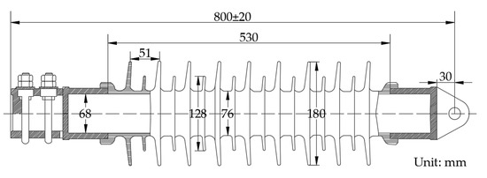
Figure 5.
Schematic of the FQBG-25/12 cantilever composite insulator.
The existing insulator contamination deposition characteristics mainly study the distribution of contamination particles on the surface of the shed. This research disregarded the hardware fittings at both ends of the insulator when the model was built. SolidWorks software was used to build the 3D model of the insulator. Figure 6 shows the established three-dimensional model of the insulator.
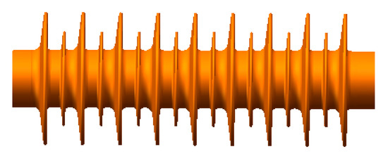
Figure 6.
Schematic of the three-dimensional insulator.
The established three-dimensional model of the insulator was imported into the mesh generation software and the calculation domain size and mesh were set. The size of the calculation domain has immense influence on the accuracy of the calculation result. Given that computational fluid mechanics generally requires that the blocking probability is not over 3%, the blocking probability was defined as follows [23]:
where L1 is the projected area of the insulator at the inlet of the calculation domain, m2; and L is the cross-sectional area of the inlet of the calculation domain, m2.
The insulator structure indicates that L1 = 180 mm × 530 mm = 0.0954 m2, the inlet area of the calculation domain set in this research was 2000 mm × 2000 mm = 4 m2, and the blocking probability was 0.024. To completely develop the fluid and prevent backflow, the length of the calculation domain was appropriately increased. Therefore, the size of the calculation domain was eventually determined to be 2000 mm × 2000 mm × 3000 mm. Airflow and contamination particles flow in from the left side of the calculation domain and flow out from the right side. For the convenience of the subsequent mesh division, the calculation domain was divided into two areas (see Figure 7).
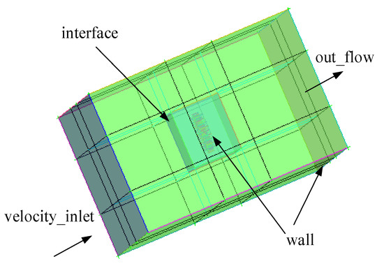
Figure 7.
Schematic of the calculation domain division.
Due to the different mesh division accuracies of the different parts and to balance the calculation accuracy and calculation resources, the use of a tetrahedral unstructured mesh in the area near the surface of the insulator can substantially fit the complex shape of the insulator. Starting from the insulator surface, it was divided by the near and far, and the quality of the tetrahedral mesh was above 0.33. The outer area used a hexahedral structured mesh, which effectively reduced the number of mesh and saved on calculation resources. The quality of the hexahedral mesh was 1. The number of mesh was approximately 1.6 million. Figure 8 shows the meshing results.
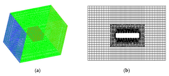
Figure 8.
Meshing results. (a) Overall insulator meshing result; (b) x = 0 planar insulator meshing result.
3.3. Boundary Condition Setting
The divided mesh was imported into the fluent fluid mechanics software, and boundary conditions were set for each surface. This study involved three types of boundary conditions. The left side of the calculation domain was defined as the velocity inlet boundary condition, the right side of the calculation domain was defined as the fully developed out flow boundary, and the insulator surface and the other four surfaces of the calculation domain were defined as the wall boundary condition. The insulator surface was set to the boundary condition of the no-slip wall. When the particles move from the air to the insulator surface of the insulator, the particle velocity is 0, which means that it remains on the surface of the insulator.
According to the related research on the measurement of the particle size of the insulator surface in the natural contamination test, the particle size distribution on insulator surface is logarithmic normal distribution, and the particle size distribution is mainly around 15 μm. The average value of particle size D10 (i.e., particle size when the cumulative probability distribution number reaches 10%) on the composite insulator surface is 2.90 μm, the average value of D50 is 8.25 μm, and the average value of D90 is 22.58 μm [24]. Therefore, in this paper, the particle size was set to 5, 10, 15, 20, and 25 μm. According to the statistics, the order of magnitude of contamination particle density (unit: g/m3) was generally about 10−5, and the particle phase was sparse phase. The particle phase volume fraction can be used to distinguish different environments. The volume fraction of contamination particles in the Gobi, sandy, and desert landforms are 0.02, 0.04 and 0.05, respectively [25]. As the research object of this paper was the catenary insulator in northwest China, the volume fraction of contamination particles under the Gobi landform was set as 0.02 as the simulation condition in this paper. It was assumed that the particles were mainly affected by drag force and gravity in the air.
3.4. Characterization Parameters of Contamination
This research used the volume fraction to characterize the degree of particle accumulation on the insulator surface. The volume fraction refers to the percentage of the particle volume on the insulator surface to the present total volume of air and particles. The volume fraction can characterize the deposition and distribution of particles on the insulator surface. The volume fraction of the particles has a positive correlation with the amount of contamination [26]. The contamination volume fraction expression is as follows:
where Vparticle is the contamination volume, m3 and Vair is the air volume, m3.
For the subsequent analysis of the distribution of contamination particles on the insulator surface, each shed should be divided into four parts: windward side, leeward side, crosswind side 1, and crosswind side 2, each of which takes an angle of 90° [27]. Figure 9 shows the division of the shed.
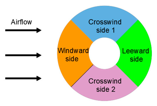
Figure 9.
Division of the insulator shed.
To accurately express the amount of the surface area contamination of the insulator, the contamination volume fractions at different locations were calculated. The calculation result used the area-weighted average of the contamination volume fractions to represent the degree of contamination accumulation. The expression of x is as follows:
where M is the area of the selected part, m2; is the contamination volume fraction on the discrete mesh nodes; Mi is the micro-element area; and n is the discrete number on M.
4. Deposition Characteristics of Particles on the Insulator Surface
4.1. Effects of the Insulator Installation Method on Contamination Deposition Characteristics
The current research used the cantilever insulator with two different installation methods (i.e., horizontal and oblique installations) as the research object. The inlet velocity was 10 m/s, particle size was 15 μm, airflow angle was 0°, and volume fraction of the particle phase was 0.02. Figure 10 shows the particle deposition cloud chart of the particles on the cantilever insulator surface. The contaminated volume data on the creepage distances along the windward, leeward, and crosswind surfaces were selected for comparison. Figure 11, Figure 12 and Figure 13 show the simulation results.
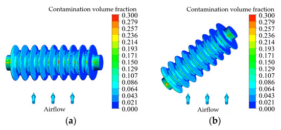
Figure 10.
Particle deposition cloud chart of the cantilever insulator. (a) Horizontal cantilever insulator. (b) Oblique cantilever insulator.
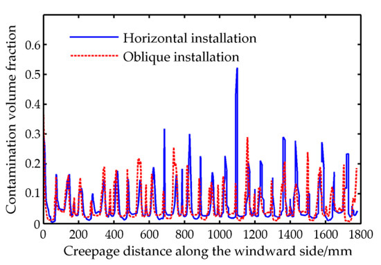
Figure 11.
Contamination volume fraction changes with the distance along the windward side.
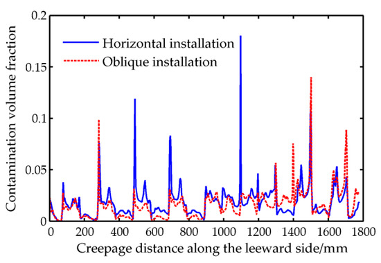
Figure 12.
Contamination volume fraction changes with the distance along the leeward side.
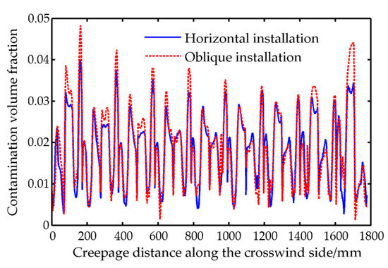
Figure 13.
Contamination volume fraction changes with the distance along the crosswind side.
Figure 11 shows that the contamination volume fraction of the windward surface of the insulator oscillates up and down with the creepage distance. These reasons are mainly related to the shape and structure of the cantilever insulator. The horizontal and oblique installation methods were similar with the creepage distance along the surface, and certain differences in the contamination volume fraction existed at certain positions. The maximum contamination volume fraction on the surface of the insulator was 0.543, which is nearly 30 times the contamination volume fraction in the air. Figure 11 illustrates that the installation method of the insulator has a certain effect on the particle deposition on the insulator surface.
Figure 12 shows that the leeward surface contamination volume fraction changes with the creepage distance were similar to the windward surface. The leeward surface contamination volume fraction with the creepage distance presented a high value in the middle and low values at both ends. When near the two ends of the insulator, the oblique installation insulator had a larger contamination volume fraction than the horizontal installation insulator. In the middle of the shed, the contamination volume fraction of the horizontal installation insulator surface was higher than that of the oblique installation insulator. The maximum contamination volume fraction of the leeward surface was 0.180, which is relatively smooth in value compared with that of the windward surface.
Figure 13 shows that the contamination volume fraction of the oblique installation insulator crosswind side was higher than that of the horizontal installation insulator at the same position. Compared with the windward and leeward surfaces, the crosswind surface had the lowest contamination volume fraction along the creepage distance. In summary, the contamination volume fraction of the windward, leeward, and crosswind surfaces of the insulator changes oscillated up and down with the creepage distance along the surface. The uneven distribution of the contamination particles on the insulator surface was evident. The shed structure of the insulator will lead to different contamination volume fractions at different positions, and the collision mode of the particles at different positions of the insulator is different. The installation method has a certain effect on the degree of contamination accumulation on the insulator surface. When the insulator is installed in the same manner, the contamination volume fraction of different parts with the creepage distance along the surface changes as follows: windward side > leeward side > crosswind side.
The change in the contamination volume fraction of the particles with the creepage distance along the surface indicated that the installation method has a significant effect on the contamination accumulation characteristics of the insulator. This study took the horizontal installation and oblique installation of insulators as the research object, and selected the middle group of sheds for the numerical simulation analysis at different particle sizes and wind velocities to compare the contamination volume fractions of the windward, leeward, crosswind, and overall surfaces of the insulator.
This study selected five working conditions: wind velocity of 10 m/s, particle phase volume fraction of 0.02, airflow angle of 0°, and particle sizes of 5, 10, 15, 20, and 25 μm. The contamination volume fraction data at different parts of the horizontal and oblique cantilever insulators were collected as well as the contamination volume fractions of the windward side, leeward side, crosswind side 1, crosswind side 2, and the entire insulator. Table 1 presents the contamination volume fraction data at different parts.

Table 1.
Contamination volume fraction of the insulator surface in different parts under different particle sizes.
Table 1 shows that the contamination volume fractions of the horizontal and oblique cantilever insulators at the same location were different under different particle sizes, and that slight differences were evident. On the windward side, when the particle size was below 10 μm, the degree of contamination accumulation of the horizontal and oblique cantilever insulators was the same. When the particle size was above 10 μm, the contamination volume fraction of the oblique cantilever insulator surface was higher than that of the horizontal cantilever insulator. For the leeward surface, the contamination volume fraction of the oblique cantilever insulator surface was lower than that of the horizontal cantilever insulator. For the crosswind surface, the contamination volume fraction of the horizontal and oblique cantilever insulator surfaces was the same when the particle size was below 15 μm. When the particle size was above 15 μm, the contamination volume fraction of the oblique cantilever insulator surface was higher than that of the horizontal cantilever insulator. For the entire insulator surface, the contamination volume fraction of the oblique cantilever insulator surface was higher than that of the horizontal cantilever insulator; the larger the particle size, the larger the difference in value. Accordingly, the installation method has a certain effect on the deposition characteristics of the particles on the insulator surface.
The effects of the installation method on the deposition characteristics of particles on the insulator surface were further studied. This research selected four working conditions for the simulation test: particle size of 15 μm, particle phase volume fraction of 0.02, airflow angle of 0°, and wind velocities of 5, 10, 15, and 20 m/s. The contamination volume fraction data at different parts of the horizontal and oblique cantilever insulators were collected as well as the contamination volume fractions of the windward side, leeward side, crosswind side 1, crosswind side 2, and the entire insulator. Table 2 shows the contamination volume fraction data at the different parts.

Table 2.
Contamination volume fraction of the insulator surface in different parts under different wind velocities.
Table 2 shows that the contamination volume fractions of the horizontal and oblique cantilever insulators at the same location were different under different wind velocities and slight differences were evident. For the windward surface, the contamination volume fraction of the oblique cantilever insulator surface was higher than that of the horizontal cantilever insulator at different wind velocities. For the leeward surface, the contamination volume fraction of the oblique cantilever insulator surface was lower than that of the horizontal cantilever insulator at different wind velocities. For the crosswind surface, the contamination volume fraction of the insulator surface increased with the increase of wind velocity, and those of the horizontal and oblique cantilever insulator surfaces were not substantially different from each other. For the entire insulator surface, the contamination volume fraction of the oblique cantilever insulator surface was consistently higher than that of the horizontal cantilever insulator at different wind velocities. Moreover, the higher the wind velocity, the larger the difference in the contamination volume fraction of the oblique and horizontal cantilever insulator surfaces.
In summary, this study comparatively analyzed the difference in the deposition characteristics of particles on the surfaces of the horizontal and oblique cantilever insulator surfaces. Our results indicate that the installation method has a significant effect on the deposition characteristics of the particles on the insulator surface. When the particle size and wind velocity are fixed for the same insulator, the degree of contamination accumulation on the insulator surface installed obliquely is higher than the insulators installed horizontally. This result is consistent with the conclusion (in Section 2) drawn by the collision deposition model of the particles with insulator surfaces in different installation methods. In the past, the horizontal and oblique cantilever insulators of the catenary usually used to be of the same type and the same creepage distance, so the creepage distance of the oblique cantilever insulator in the same catenary could be increased to prevent flashover. For example, the oblique cantilever insulator can replace an insulator with larger creepage distance or attach a booster shed, and the cleaning frequency of the oblique insulator should be greater than that of the horizontal insulator. For an area where the wind direction is relatively fixed all year round, during the cleaning process of the maintenance personnel, or during the cleaning process of the mechanized work tools, different cleaning schemes, strengths, and methods are formulated for the windward, leeward, and crosswind sides of the insulator.
4.2. Effects of Shed Structure on the Contamination Deposition Characteristics
The positive feeder insulators also belong to the catenary insulator, which are vertically connected into an insulator string to hang the positive feeder of the catenary. The aforementioned cantilever insulator is different from the positive feeder insulator in shed shape, so this paper will study the effects of shed structure on the contamination deposition characteristics of catenary insulator. The U70BS insulator can be used as a positive feeder insulator, and this study selected the U70BS porcelain insulator of disc type as the research object. The inclination angle of the U70BS insulator shed is larger than that of the cantilever insulator. Moreover, the lower surface of the shed has a number of ribs. The disc diameter of the U70BS insulator was 255 mm, height of the structure was 146 mm, and the creepage distance was 295 mm. Figure 14 shows the three-dimensional structure of the U70BS insulator.
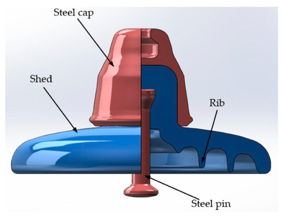
Figure 14.
Three-dimensional structure diagram of the U70BS insulator.
In the simulation, the wind velocity was 10 m/s, particle concentration was 0.02, airflow angle was 0°, and particle size was 15 μm. A piece of insulator in the middle was selected for analysis. Figure 15 shows the particle deposition cloud chart of the particles on the U70BS insulator surface.
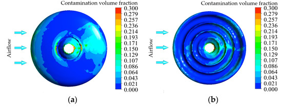
Figure 15.
Particle deposition cloud chart of the U70BS insulator. (a) Upper surface of the shed; (b) lower surface of the shed.
Figure 15 shows that for the upper surface, the particles were mainly deposited on the windward and leeward surfaces, and the crosswind surface was relatively small. The contamination accumulation of the leeward surface was more extensive compared with those of the windward and leeward surfaces. For the lower surface, the particles were also mainly deposited on the leeward surface, and the particles were deposited minimally in other areas. The contamination volume fractions of the windward, leeward, crosswind 1, and crosswind 2 were extracted, and their values were 0.0350, 0.0480, 0.0202, and 0.0196, respectively. The degree of contamination accumulation on the different parts of the insulator surface is as follows: leeward side > windward side > crosswind side.
To study the deposition characteristics of particles on the positive feeder insulator under different conditions, this research simulated and analyzed the distribution of particles on the insulator surface under different wind velocities and different particle sizes. The effects of wind velocity on the particle deposition characteristics of the positive feeder insulator surface were analyzed. In the simulation, the fixed particle size was 15 μm, airflow angle was 0°, particle concentration was 0.02 and wind velocities were 1, 5, 10, 15, and 20 m/s. Given the top effects at both ends of the insulator, the second shed in the middle was selected to calculate the contamination volume fractions of the windward, leeward, crosswind 1, and crosswind 2 surfaces at different wind velocities. Figure 16 shows the changes of the contamination volume fraction of the positive feeder insulator surface with wind velocity.
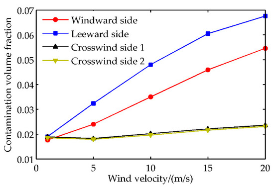
Figure 16.
Positive feeder insulator surface contamination volume fraction changes with wind velocity.
Figure 16 shows that the contamination volume fraction of the windward, leeward, and crosswind surfaces of the positive feeder insulator increased with an increase in wind velocity. This result was the same as the change of the cantilever insulator surface with wind velocity. At the same wind velocity, the contamination volume fraction of the windward side of the positive feeder insulator was consistently less than the leeward side, and the contamination volume fraction of the windward side of the cantilever insulator was constantly higher than the leeward side, thereby forming a sharp contrast. Evidently, the shed structure has substantial effects on the deposition law of particles on the windward and leeward sides of the insulator.
The effects of particle size on the deposition characteristics of the positive feeder insulator surface were likewise analyzed. In the simulation, the fixed wind velocity was 10 m/s, airflow angle was 0°, particle concentration was 0.02, and particle sizes were 5, 10, 15, 20, and 25 μm. The contamination volume fractions of the windward, leeward, crosswind 1, and crosswind 2 surfaces with different particle sizes were also calculated. Figure 17 shows the change in the contamination volume fraction of the positive feeder insulator surface with the particle size.
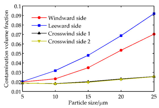
Figure 17.
Positive feeder insulator surface contamination volume fraction changes with particle size.
Figure 17 shows that the contamination volume fractions of the windward, leeward, and crosswind surfaces of the positive feeder insulators increased with the gradual increase of the particle size, and the windward and leeward surfaces grew faster than the crosswind 1 and crosswind 2. The law of the contamination volume fraction on the insulator surface with the particle size is consistent with the wind velocity law. At the same particle size, the windward surface contamination volume fraction of the positive feeder insulator was constantly less than the leeward surface contamination volume fraction, and the cantilever insulator windward surface contamination volume fraction was constantly higher than the leeward surface contamination volume fraction, thereby forming a sharp contrast. Evidently, the insulator shed structure has substantial effects on the deposition characteristics of particles on the insulator surface.
The preceding analysis indicated that when the wind velocity and particle size are fixed, the positive feeder insulator has a distinct difference from the windward and leeward sides of the cantilever insulator. This result is considerably related to the structure of the insulator shed. The possible reason is that the inclination angles of the upper and lower sheds of the cantilever insulator is close to the horizontal, thereby resulting in difficulty forming a large vortex area on the leeward surface. The majority of the particles are deposited on the windward surface of the insulator, and the particles are difficult to deposit on the leeward surface. However, the leeward area forms a large vortex area due to the larger disc diameter of the positive feeder insulator, and the particles are mainly deposited on the leeward surface. In the same environment, the contamination characteristics of insulators with different shed shapes are different, so the description of the contamination characteristics of insulators should be based on a certain shed structure.
5. Conclusions
According to the above results, the following conclusions can be obtained:
- (1)
- From a microscopic point of view, the gas–solid two-phase flow theory was used to establish the collision deposition model of particles and the surfaces of the horizontal and oblique cantilever insulators. The deposition conditions of the particles on the insulator surface were obtained according to the conservation of kinetic energy. When particle size and wind speed are fixed, the ejection velocity of the oblique cantilever insulator surface is less than that of the horizontal cantilever insulator, and the particles are easily deposited on the surface of the oblique cantilever insulator.
- (2)
- In the horizontal and oblique installation methods, the contamination volume fractions of the windward, leeward, and crosswind surfaces showed up and down oscillations with the creepage distance. The uneven distribution of contamination particles on the insulator surface was evident. At the same location, a certain difference existed in the contamination volume fraction of the insulator surface of the horizontal and oblique cantilever insulators. For the entire insulator surface, the degree of contamination accumulation on the oblique cantilever insulator surface was consistently higher than that of the horizontal cantilever insulator. The installation method of the insulator had a significant effect on the contamination deposition characteristics.
- (3)
- It is recommended to increase the creepage distance of the oblique cantilever insulator or attach a booster shed to deal with the situation of large contamination accumulation and easy contamination flashover. For an area where the wind direction is relatively fixed all year round, during the cleaning process of the maintenance personnel, or during the cleaning process of the mechanized work tools, different cleaning schemes, strengths, and methods can be formulated for the windward, leeward and crosswind sides of the insulator.
- (4)
- The shed structure of the insulator has a significant effect on the contamination deposition characteristics of the insulator. With the increase in wind velocity and particle size, the contamination volume fraction on the windward side of the cantilever insulator is constantly higher than the leeward side, the contamination volume fraction of the positive feeder insulator on the windward side is constantly less than the leeward side. The description of the contamination characteristics of insulators should be based on a certain shed structure.
Author Contributions
The research concepts were proposed by S.Z., C.Z., D.Z., and Y.Z. Data processing and manuscript preparation were conducted by Y.Z. and D.Z. Data analysis and interpretation were implemented by S.Z., C.Z., and D.Z. Manuscript editing and visualization were performed by S.Z. and C.Z. All authors have read and agreed to the published version of the manuscript.
Funding
This work was financially supported by the Natural Science Foundation of China (Grant Nos. 51867013; 51767014; 51567014).
Conflicts of Interest
The authors declare no conflicts of interest.
References
- China Railway Corporation. The Technology of High-speed Railway Catenary; China Railway Press: Beijing, China, 2014; pp. 1–6. [Google Scholar]
- Zhao, S.; Zhang, C.; Zhang, Y.; Wang, S. Influence of partial arc on electric field distribution of insulator strings for electrified railway catenary. Energies 2019, 12, 3295. [Google Scholar] [CrossRef]
- Skopec, A.; Wankowicz, J.G.; Sikorski, B. Electric field calculation for an axially-symmetric insulator with surface contamination. IEEE Trans. Dielectr. Electr. Insul. 1994, 1, 332–339. [Google Scholar] [CrossRef]
- Bo, L.; Gorur, R.S. Modeling flashover of AC outdoor insulators under contaminated conditions with dry band formation and arcing. IEEE Trans. Dielectr. Electr. Insul. 2012, 19, 1037–1043. [Google Scholar] [CrossRef]
- Zhang, Z.; You, J.; Wei, D.; Jiang, X.; Zhang, D. Investigations on AC pollution flashover performance of insulator string under different non-uniform pollution conditions. IET. Gener. Transm. Distrib. 2016, 10, 437–443. [Google Scholar] [CrossRef]
- Xu, J.; Yin, F.; Li, L.; Wen, Q.; Wang, H.; Liu, S.; Jia, Z.; Farzaneh, M. Wet snow flashover characteristics of 500-kV AC insulator strings with different arrangements. Appl. Sci. 2019, 9, 930. [Google Scholar] [CrossRef]
- Jiang, X.; Wang, Q.; Zhang, Z.; Hu, J.; Hu, Q.; Zhu, C. Ion migration in the process of water freezing under alternating electric field and its impact on insulator flashover. Energies 2017, 10, 61. [Google Scholar] [CrossRef]
- Dong, H.; Zhang, Y.; Dou, J.; Dong, H.; Su, K. Numerical analysis of contamination characteristics of new type insulator for catenary cantilever. High Volt. Eng. 2019, 45, 2267–2275. [Google Scholar]
- Sun, J.; Gao, G.; Zhou, L.; Wu, G. Pollution accumulation on rail insulator in high-speed aerosol. IEEE Trans. Dielectr. Electr. Insul. 2013, 20, 731–738. [Google Scholar]
- Jiang, Z.; Jiang, X.; Guo, Y.; Hu, Y.; Meng, Z. Pollution accumulation characteristics of insulators under natural rainfall. IET. Gener. Transm. Distrib. 2017, 14, 1479–1485. [Google Scholar] [CrossRef]
- Li, H.; Lai, J.; Lei, Q.; Deng, S.; Liu, G.; Li, L. Collision and adsorption of pollution particles on the surface of electrical insulator. High Volt. Eng. 2012, 38, 2596–2603. [Google Scholar]
- Horenstein, M.N.; Melcher, J.R. Particle contamination of high voltage DC insulators below corona threshold. IEEE Trans. Electr. Insul. 1979, 6, 297–305. [Google Scholar] [CrossRef]
- Hernandez-Corona, R.; Ramirez-Vazquez, I.; Montoya-Tena, G. Evaluation of 23 kV insulator profiles with different pollution levels. In Proceedings of the 2004 IEEE International Symposium on Electrical Insulation, Indianapolis, IN, USA, 19–22 September 2004; pp. 304–307. [Google Scholar]
- Jiang, Z.; Jiang, X.; Jiang, Y.; Li, Y. Natural contamination characteristics of suspension insulator in Hunan Province. J. Cent. South Univ. (Sci. Tec.). 2018, 49, 1683–1690. [Google Scholar]
- Lv, Y.; Li, J.; Zhao, W. Model optimization of pollution deposition criterion of insulators based on energy. IEEE Trans. Dielectr. Electr. Insul. 2017, 24, 2920–2929. [Google Scholar] [CrossRef]
- Zhang, M.; Wang, R.; Li, L.; Jiang, Y. Size distribution of contamination particulate on porcelain insulators. Coatings 2018, 8, 339. [Google Scholar] [CrossRef]
- Slama, E.A.; Beroual, A.; Hadi, H. Influence of pollution constituents on DC flashover of high voltage insulators. IEEE Trans. Dielectr. Electr. Insul. 2013, 20, 401–408. [Google Scholar] [CrossRef]
- Lv, Y.; Zhao, W.; Yan, W.; Liu, Y. Optimization of the contamination particle deposition model based on humidity and surface energy. Appl. Therm. Eng. 2019, 157, 113734–113741. [Google Scholar] [CrossRef]
- Ren, J. Particle Dispersion Science and Technology; Chemical Industry Press: Beijing, China, 2005; pp. 66–72. (In Chinese) [Google Scholar]
- Zhang, W.; Qi, H.; You, C.; Bao, Y.; Xu, X. Particle collision simulation and numerical study. In Proceedings of the Chinese Society of Engineering Thermophysics 2002 Conference on Multiphase Flow Technology, Dalian, China, 1 October 2002; pp. 396–402. [Google Scholar]
- Ge, T.; Jia, Z.; Zhou, K. Research on elastoplastic normal impact of steel spheres against a rigid plane. Eng. Mech. 2008, 25, 209–213. [Google Scholar]
- Zhang, Z.; Zhang, D.; Jiang, X.; Liu, X. Study on natural contamination performance of typical types of insulators. IEEE Trans. Dielectr. Electr. Insul. 2014, 21, 1901–1909. [Google Scholar] [CrossRef]
- Zeng, K.; Wang, C.; Huang, B.; Zhou, D. Analysis and suggestion of several key influencing factors in computational wind engineering. Acta Aerody. Sin. 2007, 25, 504–508. [Google Scholar]
- Zhang, Y.; Su, J.; Liu, H.; Li, J.; Zhang, Y.; Liu, G. Particle size distribution characteristics of naturally polluted insulators in service of HVDC transmission line. High Volt. Eng. 2017, 43, 173–180. [Google Scholar]
- Shi, L.; Jiang, F.; Han, F. Numerical simulation of response law of wind-blown sand flow around the railway embankment. J. Rail. 2014, 36, 82–87. [Google Scholar]
- Sun, J.; Luo, S.; Wu, G.; Gao, G.; Yang, K.; Hu, X. Pollution distribution characteristic of high-speed train roof insulator and its optimization strategy. J. Southwest Jiaotong Univ. 2014, 49, 343–350. [Google Scholar]
- Tang, Q. Contamination Characteristics and Electric Field Distribution of High Voltage Insulators. Master’s Thesis, Suzhou University, Suzhou, China, 1 May 2017. [Google Scholar]
© 2020 by the authors. Licensee MDPI, Basel, Switzerland. This article is an open access article distributed under the terms and conditions of the Creative Commons Attribution (CC BY) license (http://creativecommons.org/licenses/by/4.0/).