Article

Graphene Coating for Enhancing the Atom Oxygen Erosion Resistance of Kapton

1
Beijing Key Laboratory for Powder Technology Research and Development, Beihang University (BUAA), Beijing 100191, China
2
Technology and Engineering Center for Space Utilization, Chinese Academy of Sciences, Beijing 100094, China
3
State Key Laboratory of Mechanics and Control of Mechanical Structures & Key Laboratory for Intelligent Nano Materials and Devices of Ministry of Education & College of Aerospace Engineering, Nanjing University of Aeronautics and Astronautics (NUAA), Nanjing 210016, China
4
State Key Laboratory of Explosion Science and Technology, Beijing Institute of Technology, Beijing 100081, China
*
Authors to whom correspondence should be addressed.
Coatings 2020, 10(7), 644; https://doi.org/10.3390/coatings10070644
Submission received: 9 June 2020 / Revised: 27 June 2020 / Accepted: 29 June 2020 / Published: 1 July 2020
(This article belongs to the Section Corrosion, Wear and Erosion)

Abstract

:
Atom oxygen (AO) can cause most spacecraft material erosion seriously. Liquid-exfoliated graphene by jet cavitation was used to coat Kapton employed on spacecraft to enhance its AO erosion resistance. The coating was prepared by vacuum filtering and transferring. After AO exposure, compared with naked Kapton, the mass loss of coated Kapton reduced to 3.73% and the erosion yield reduced to 3.67%. AO reacted with graphene and then was left in the coating. The coating was degenerated slightly, but still performed well. We believe that graphene coating could be potentially applied to increase the material’s life span on spacecraft.

1. Introduction

Atom oxygen (AO), the main component of atmosphere in the low earth orbit, can cause most spacecraft material erosion seriously, and then affect the normal operation of the spacecraft [1,2]. With the AO translational energy 4.5–5 eV, polymer bond can be easily broken and induced oxidative decomposition [3,4]. Polyimide (named by “Kapton”) is widely used to cover the external surface of spacecraft, because of its chemical and heat stability [5,6]. It has been experimentally evidenced that Kapton is severely eroded by AO in space flight [1,7]. The erosion yield (Ey), which represents the volume loss of material per AO, is 3 × 10⁻²⁴ cm3/atom [8].
Nowadays, various kinds of coatings by chemical methods have been be applied to protect Kapton from AO erosion: hybrid inorganic/organic polymers coating [9], silica coating [10,11,12], boehmite-AlOOH coating [13], hybrid silica coatings [14,15], polysilazane coating [16], titanium oxide coating [17], SnO2 coating [18], etc. For these coatings, sol–gel and copolymerizing are most frequently-used, and strong acid and alkali are employed, which are environmentally unfriendly. There are also many other coatings by physical methods: multilayer silica/alumina coating [19]; SiOx coating [20]; Mg-alloy coating [21]. Sputtering or plasma deposition are commonly employed, which needs some severe conditions such as high vacuum, high energy, high temperature, etc. Therefore, it restricts their industrial application.
Graphene is a two-dimension nanomaterial which has excellent experimental characteristics, and has shown great application prospects in various fields [22,23,24,25]. It has very rich sources which are easy to be obtained, including graphite, organic fragments, or even biomass wastes and so on [26]. While it can also be made into graphene fibers to expand the application fields, such as healthcare, energy, communication, reinforcement and so on [27]. Specifically, the monolayer graphene membrane has been demonstrated to be used as gas barrier [28], and the defects in graphene will not influence its application in impermeable nanomembranes [29]. Although AO can oxidize graphene with ease and then form strong chemical bonds on its surface, but it’s hard for AO to pass through. This is because the requested energy of passing through monolayer graphene is more than 5.98 eV, while AO translational energy is only 4.5–5 eV, which is obviously insufficient [30]. Thus it’s definitely harder for AO to permeate multilayer graphene.
Up to now, there are a few studies applying graphene and its derivative to resist AO erosion. Zhang et al. grew multilayers graphene on copper by chemical vapor deposition (CVD) [31]. Ren et al. grew nitrogen-doped graphene coating on copper by CVD [32]. Chen et al. grafted GO and silane onto p-phenylene benzobisoxazole fibers through chemical reaction [33]. Peng et al. modified carbon fiber-reinforced cyanate ester composites by polyhedral oligomeric silsesquioxane-graphene-TiO2 through melt method [34].
In 2011, our group first developed the jet cavitation method to prepare liquid-exfoliated graphene, which can produce graphene on a large scale [35]. We try to explore its potential to improve AO erosion resistance. Zhang et al. [36] and Liu et al. [37] prepared graphene-reinforced epoxy resin nano-composites and graphene-reinforced cellulose acetate composite respectively. In especial, Yi et al. selected few-layer graphene to prepare the polyvinyl alcohol composites [38]. Though good protective effect was obtained, but the AO resistance remains a relatively low degree (40–65% decrease in mass loss). That can be attributed to the undercutting peculiar to AO [39]. Therefore, it’s particularly important to protect the material surface from intrusion, while graphene coating might be the right answer. To date, the ability of graphene coating to improve the AO erosion resistance has not been extensively investigated.
There are several methods for graphene to coat a flexible substrate, such as layer transfer (graphene by CVD) [40] and spin coating (GO) [41]. It’s investigated that Vander Waals forces is strong enough to bond graphene and substrate [42]. In this paper, graphene coatings were prepared by filtering graphene dispersion onto organic filter membrane with a vacuum pump, and afterwards the graphene film was transferred onto Kapton. The ground-based AO effect simulation facility was employed to carry out the AO exposure experiment [43]. The AO erosion resistance of graphene coating was evaluated and the mechanism was discussed. Both the preparation of graphene and its coating method will be helpful for industrial production because of their low cost.

2. Experimental

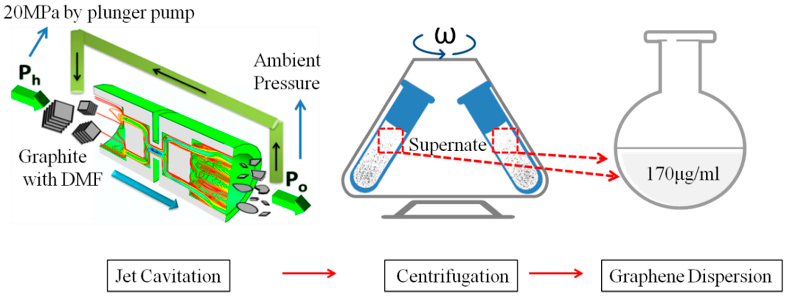
2.1. Preparation of Graphene Dispersion

Graphite (Alfa Aesar, 43209, Shanghai, China) was used for preparing graphene. Jet cavitation method reported by our group previously was employed to prepare graphene dispersion [35]. Firstly, graphite was dispersed in N,N-Dimethyl formamide(DMF) [44] (3 mg/mL), and then cycling flowed in the jet cavitation device (pressure20 MPa, 4 h). Secondly, the dispersion above was treated by a centrifuge (L-600, Changsha XiangYi, Changsha, China, 2000 rpm, ×568 g, 0.5 h). The concentration of supernate collected from the centrifugal dispersion was 170 μg/mL (calculated from the dispersion absorbance obtained by a double-beam ultraviolet spectrophotometer (TU1901, Beijing Puxi General Instrument Co., Ltd., Beijing, China). Figure 1 shows the preparation process of graphene dispersion.

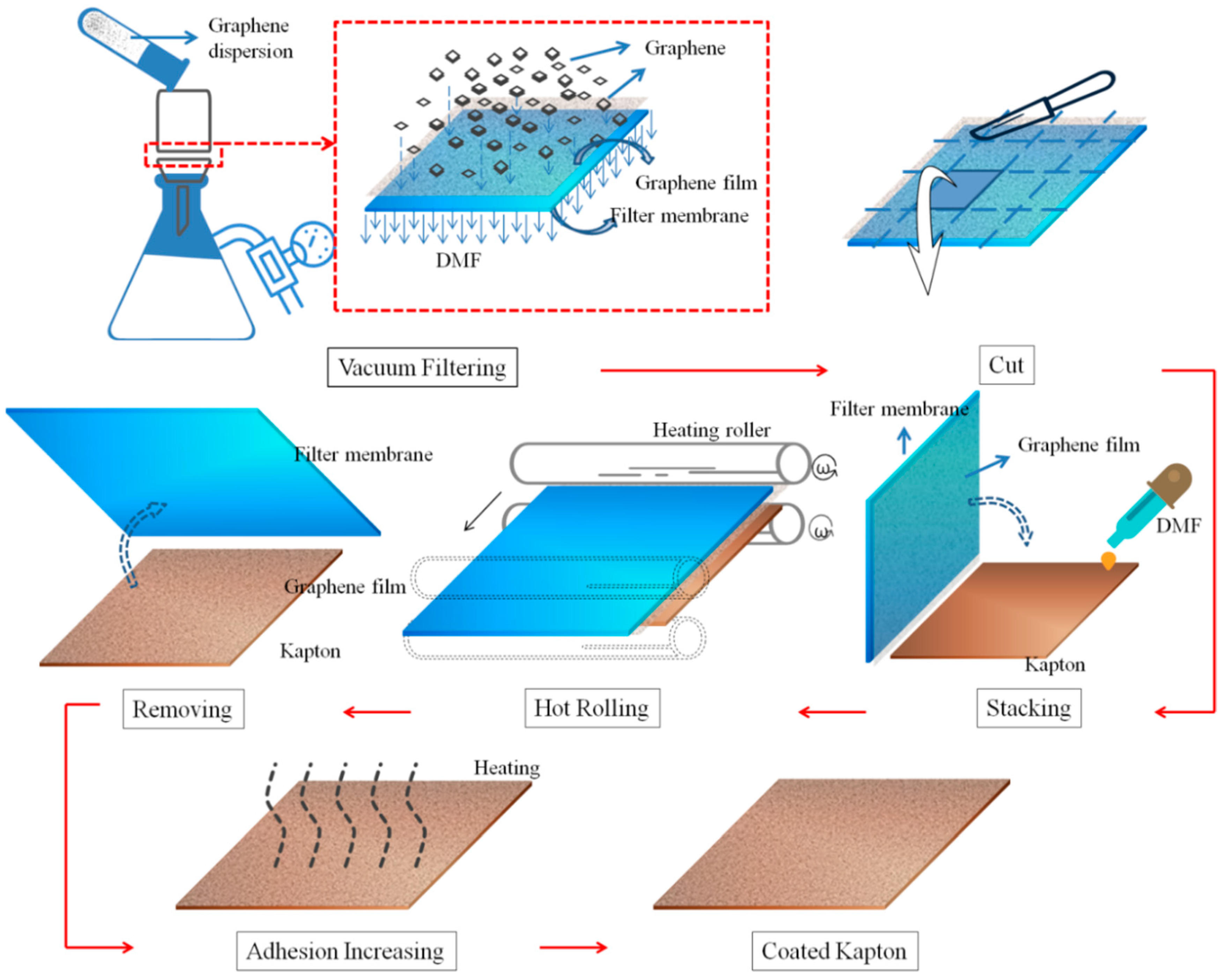
2.2. Preparation of Graphene Coatingon Kapton

The graphene film was obtained by vacuum filtering the graphene dispersion (170 μg/ml) onto nylon membranes, and then transferring the graphene film onto the Kapton. This method can get uniform coating thickness, and control the coating thickness easily via changing the concentration or volume of the dispersion [46].
First, Kapton was cut into square of 15 mm, cleaned in acetone by a ultrasonic cleaner (KX-1620HG, 28KHz, Kexi, Beijing, China) for 10 min, and dried for use [47]. Second, different volume (1, 2, 3, 4 mL) of the 170 μg/mL graphene dispersion prepared previously was diluted by 60 mL deionized water, and then was filtered through a nylon membrane (φ50 mm, aperture size 450 nm, Shanghai Xinya, Shanghai, China) on a filter (2000 mL, Jiangsu Sanaisi, Jiangsu, China) by a vacuum pump (GM-0.33A, Tianjin Jinteng, Tianjin, China, pumping rate 20 L/min) [48]. Thus the graphene loadings on nylon membrane (mass of graphene per square centimetre) are 8.7, 17.3, 26.0, 34.6 μg/cm2. It’s worth noting that the graphene dispersion should be transferred into the filtering funnel very slowly to avoid air bubbles. Third, the wet nylon membrane with graphene was cut into square of 20 mm and immediately pasted onto Kapton with graphene against the Kapton surface with some pressure. Meanwhile, DMF was supplied to the edge of Kapton to extrude bubbles within the gaps between Kapton and graphene film. Subsequently, the adhesive layers was hot rolled by a roll laminator(FL271, Feiniao, Beijing, China, 30 min, 150 °C). After hot rolling, the adhesion force of nylon membrane decreased in a great extent and then were peeled off carefully [49]. Thus the graphene film was transferred onto the target substrate Kapton. Finally, the coated Kapton was heated at 140 °C in a vacuum drying oven for 10 h. This heat treatment can remove the DMF and reduce the gap between the graphene and the Kapton, resulting in increase of the adhesion [50,51]. So far we completed the Kapton coating of graphene. Figure 2 shows the coating process.

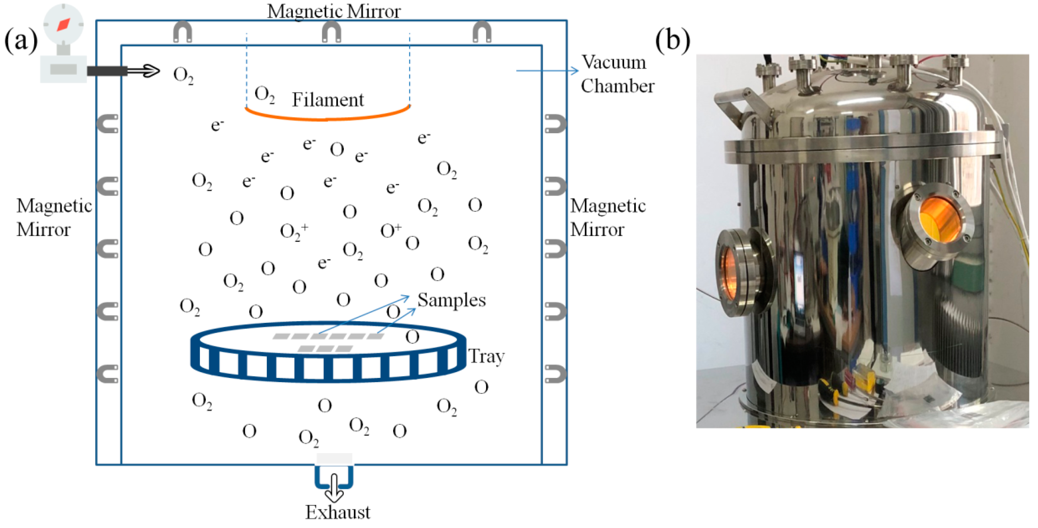
2.3. AO Exposure Experiment

The AO exposure experiment was carried out in the ground-based AO effects simulation facility designed by our group [43] (pressure 0.15 Pa, 48 h). Figure 3 shows the schematic of the experiment and the simulation facility. In vacuum chamber the heated filament liberates electrons (e), which can decompose and ionize the oxygen molecules (O2) into AO and oxygen ion (O2+, O+). Lots of permanent magnets arranged in the vacuum chamber wall limit the plasma (e, O2+, O+) in the middle part. The AO proportion is 3 orders higher that of ion by testing [43]. Therefore the effect of ion on samples is negligible, and AO is the dominant component in the experiment. In order to investigate the erosion resistance of the graphene coating under different AO flux, we took out the samples from the vacuum chamber of simulation facility at 8, 16, 24, 32, 40, 48 h. The corresponding AO flux were 1.11, 2.28, 3.54, 4.87, 5.93, 7.09 × 10²⁰ atoms/cm2, which were obtained from the mass loss of naked Kapton [36] (Ey = 3 × 10⁻²⁴ cm3/atom). The 48 h AO flux (7.09 × 10²⁰ atoms/cm2) was equivalent to 103 days exposure in space environment (altitude 400 km, average value of solar activity, AO number density108 atoms/cm3, the spacecraft orbiting at 8 km/s) [52].

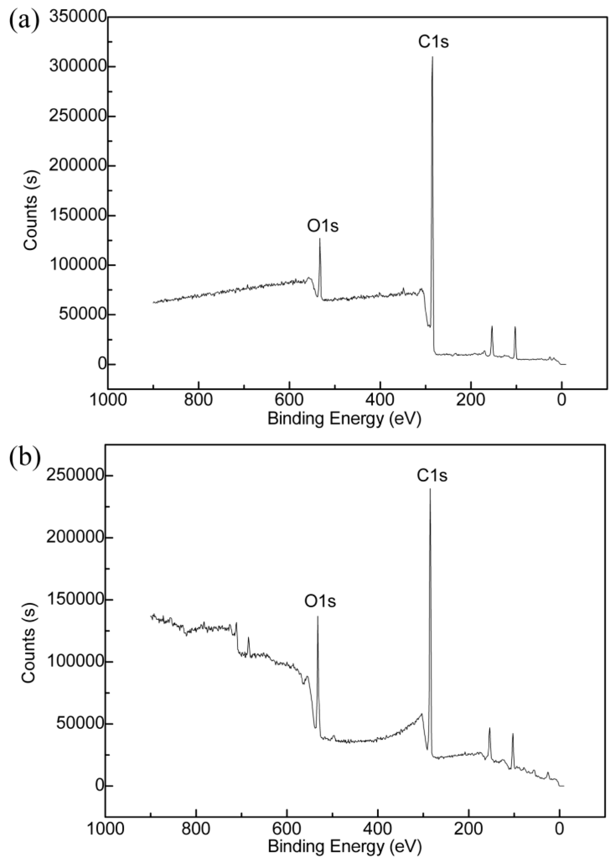
2.4. Characterization

Transmittance spectra of coated Kapton was evaluated by a double-beam ultraviolet spectrophotometer (TU1901, Beijing Puxi General Instrument Co., Ltd., Beijing, China). Atomic force microscope (AFM) (MultiMode V8, ScanAsyst mode, Bruker Nano Inc., New York, NY, USA) was used to investigate the height information and morphology. The Raman spectrum (Rm2000, 514 nm laser, Renishaw Ltd., London, England) were made on dried graphene film. The balance (BT 25S, Beijing Sartorius, Beijing, China, sensitivity 0.01 mg) was used to measure the mass of samples. Scanning electron microscopy (SEM) (LEO-1530VP, Carl Zeiss AG, Oberkochen, Germany) was employed to measure the surface morphology. X-ray photoelectron spectrometer (XPS) (ESCALAB-250, Thermo Fisher Scientific Inc., Boston, MA, USA) was uesd to investigate surface compositions.

3. Results and Discussion

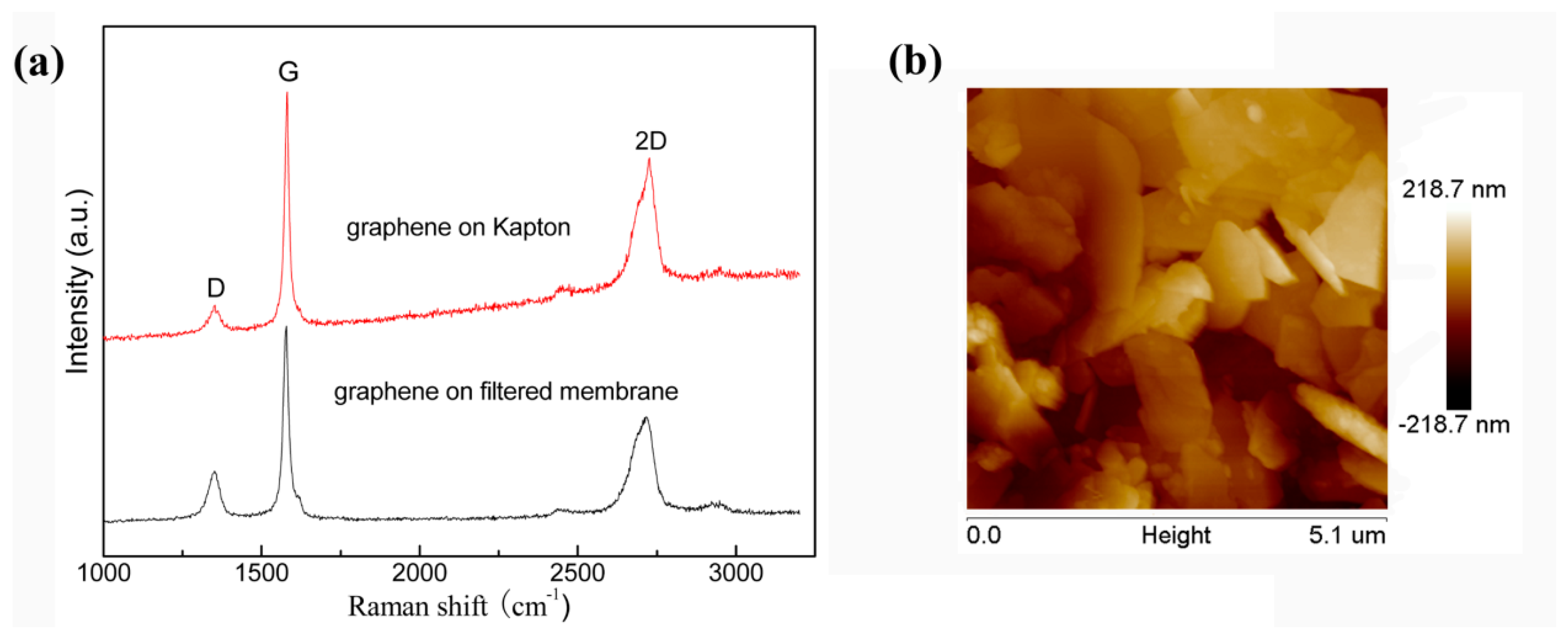
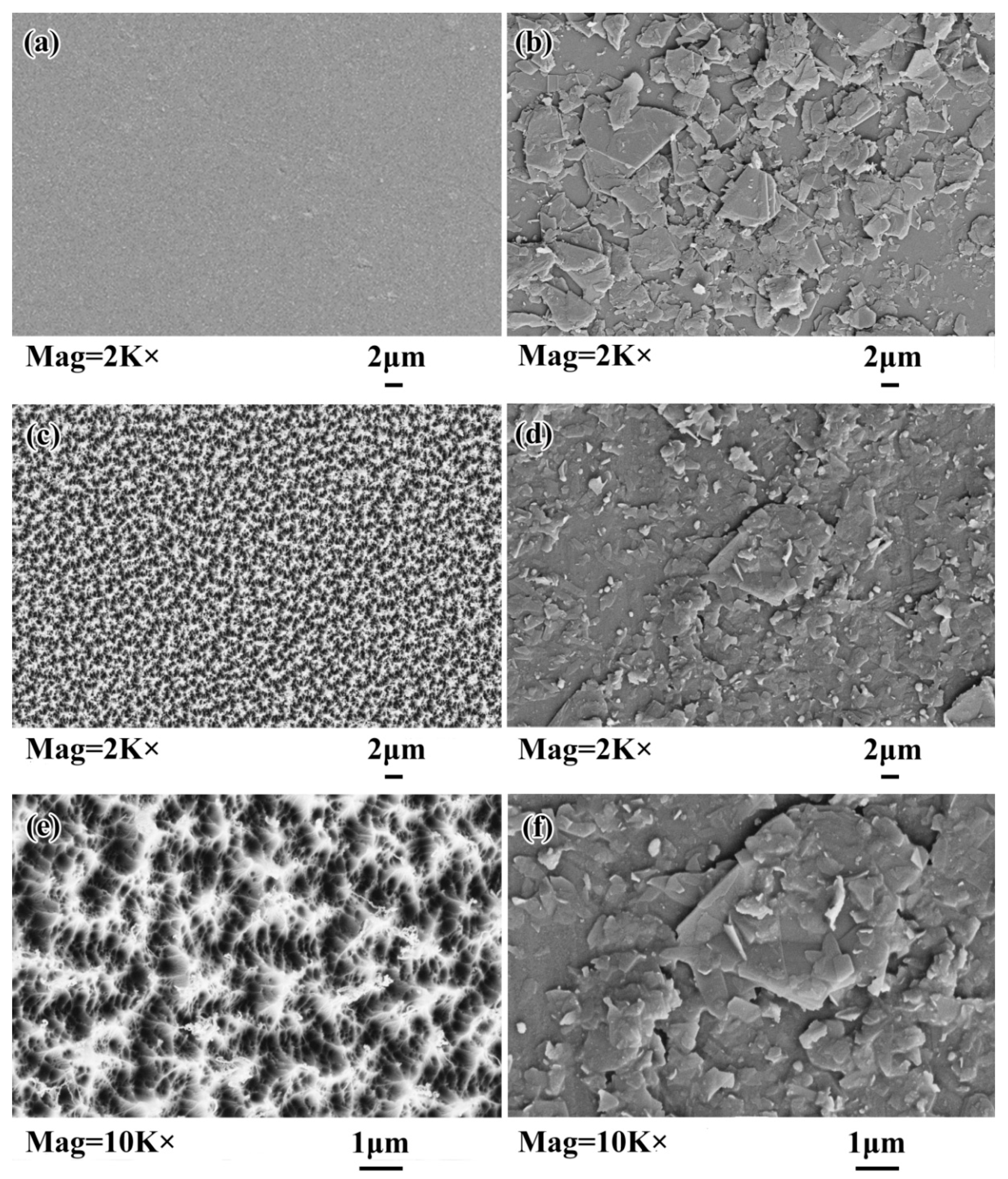
3.1. Graphene and Graphene Film Prepared

To understand the characters of the graphene prepared, AFM was utilized to gain the thickness and size information visually. Figure 4a is the photograph of graphene dispersion. Figure 4b shows the AFM image which can indicate that the number of graphene layers is less than 3. Figure 4c illustrates Raman spectra of a dried graphene cake and pristine graphite powder. While 2D band in Raman spectra can reflect information of graphene layers. It is observed that the 2D band of the graphene cake and the pristine graphite shows a marked difference, which indicates the success of graphene preparation [53]. In addition, the rise of D band illustrates that some defects were introduced into the graphene during the preparation process [54].
Our group have done detailed analysis on the nature of graphene films prepared by vacuum filtration in 2014. The following vacuum filtration process didn’t drive graphene flakes into bulk graphite, but only made the graphene flakes stacked to form multi-layer structure [55]. However, in the following transfer process, the nature of the films still attracts our attention. So we investigate the Raman spectra of the film before and after the transfer, as is shown in Figure 5a. It worth noting that the Raman spectra reflects the condition around the whole scope. Intuitively, no significant change appears in D band which can indicate the defects degree. Therefore, the transfer process of graphene film has few cracks and tears, which implies the graphene film was successfully transferred onto Kapton. In addition, the nearly indistinguishable 2D band on Kapton and filtered membrane illustrates that there is few change inside the multi-layer structure [53]. In other words, we transfer the graphene coating without losing naure of the film. Therefore the coating on Kapton is still the multi-layer structure constituted by graphene flakes. Furthermore, the morphology feature of graphene coating on Kapton was revealed by the AFM image (Figure 5b). As shown, aggregation was introduced into the graphene coating, but the film still has good continuity.
It’s investigated that Van der Waals forces is strong enough to bond the graphene and the substrate, and also graphene flakes in the coating. In addition, this strong adhesive force are not limited to any substrate since Van der Waals forces exist everywhere [42]. For instance, the graphene oxide (GO) coating prepared by the same method can retain its reliability after a series of lithographic processes [56]. Therefore, it can be concluded that the graphene coating has a good binding force with the substrate Kapton.
In addition, we investigated the transmissivity of coating samples with different graphene loadings (8.7, 17.3, 26.0, 34.6 μg/cm2) by ultraviolet spectrophotometer, as shown in Figure 6. It can be seen that the transparency is still preserved to some extent after coating and the transmissivity decrease with the graphene loadings increase. Consequently, balancing between transparency and AO erosion resistance should be determined by the requirements of practical applications.

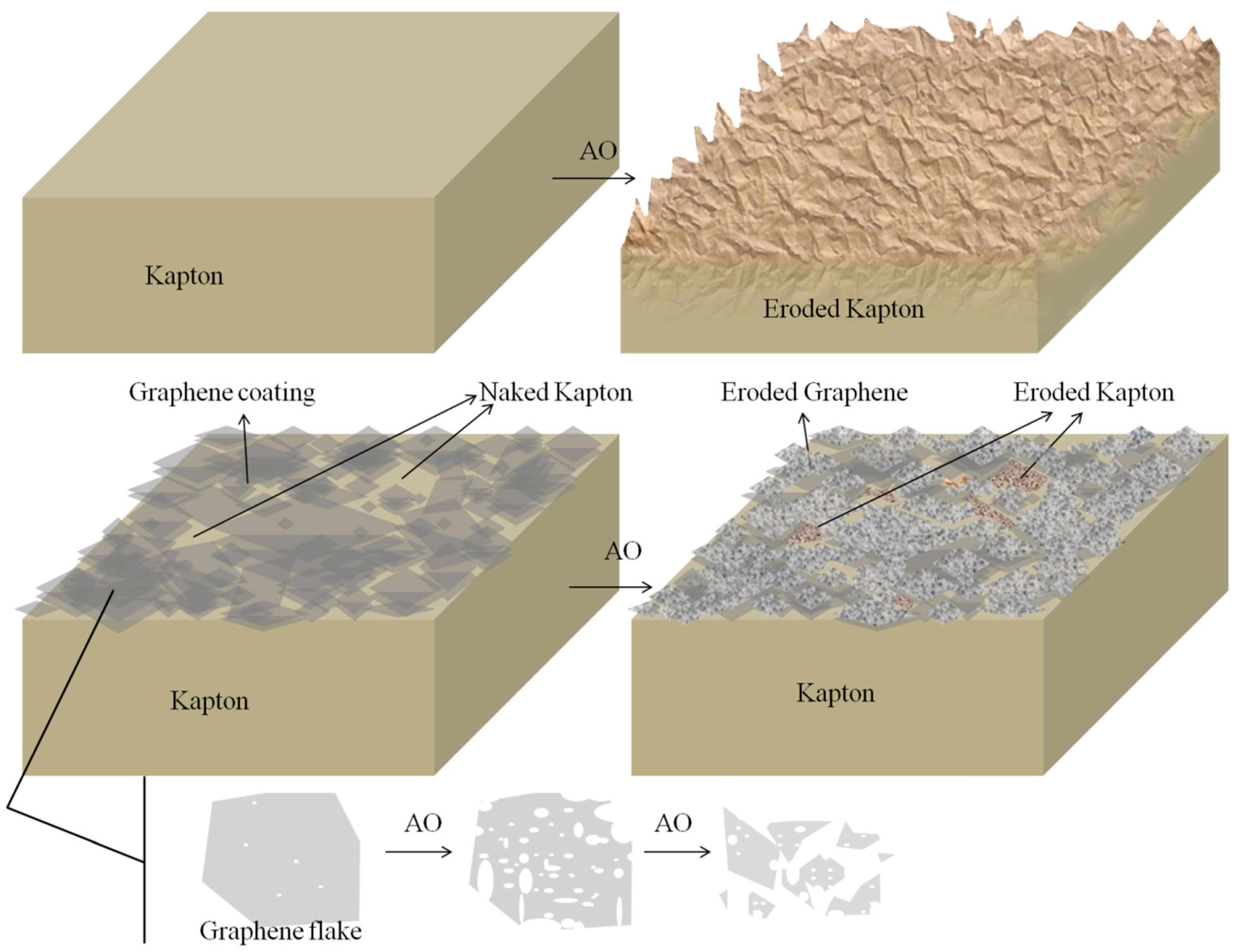
3.2. AO Resistance of Coated Kapton

As shown in Figure 7 and Figure 8, the mass loss (M-L, the reduction in weight of sample) and Ey of coated Kapton with different graphene loadings were recorded. Ey can be calculated from the M-L of samples via the the following equation. Δ M S is the M-L of samples (g), ρ is the density of Kapton (1.4 g/cm3), A is the area of the sample (cm2), F is the AO flux (atoms/cm2).
E y = Δ M S ρ AF
The graphene loadings on Kapton were 8.7, 17.3, 26.0, 34.6 μg/cm2. Higher graphene loading means thicker film [46]. It can be illustrated from Figure 7 and Figure 8 that the M-L and Ey of coated Kapton had dramatic drops compared with the naked Kapton, demonstrating the excellent protective effects of the graphene coatings. In addition, both the M-L and Ey first decrease and then increase with the increase of graphene loading. For the graphene loading of 26.0 μg/cm2, in the early exposure of 16 h (AO flux: 2.28 × 10²⁰ atoms/cm2), there was negligible M-L and Ey. After 48 h exposure (AO flux: 7.09 × 10²⁰ atoms/cm2), the M-L and the Ey of coated Kapton are only 3.73% and 3.67% of those of the naked Kapton, respectively. But if the graphene loading is further increase from 26.0 to 34.6 μg/cm2, the performance is degraded.
There are two factors that affect the resistance to AO erosion. One is self nature of the coating material. The other is compactness and completeness of the coating. A study on graphene by CVD against AO erosion was developed, which concludes that multilayer graphene has better AO resistance than monolayer grapheme [31]. In our study, the graphene coatings are prepared by stacking graphene flakes, which can increase the number of graphene layers in a sense. Therefore, in coating’s self nature of AO resistance, it’s a positive effect that graphene loading increases. Therefore, in consideration of the degradation of the coating with 34.6 μg/cm2 graphene loading, the compactness and completeness of the coating may be the negative factor. This may attribute to the severe aggregation caused by high graphene loading. Based on our experimental data here, the optimal graphene loading is found to be around 26.0 μg/cm2.
Meanwhile, we investigated the Ey of coated Kaptonin a different dimension, as shown in Figure 9. It can be illustrated that the Ey is high and stable in the naked Kapton, while those are much lower in the coated Kapton. Meanwhile, the Ey slightly increase with the exposure time increases, indicating lower AO erosion resistance at high AO flux. This may be attributed to that high AO flux can cut the graphene flakes into smaller pieces and then generate more edge structure [57,58,59], resulting in more cracks to destroy the completeness and compactness of the coatings.
It is worth reminding that the Ey of carbon-carbon-fiber (C–C) composites, highly oriented pyrolytic graphite (HOPG), and pyrolytic graphite (PG) are 1.093, 0.538, 0.692 × 10⁻²⁴ cm3/atom respectively [60]. Among these carbon materials, HOPG was employed to prepare graphene [61]. Yet the Ey of all coated samples in this study are nearly under 0.5 × 10⁻²⁴ cm3/atom, and especially the one with graphene loading of 26.0 μg/cm2 is an order of magnitude lower. Hence, this provides side evidence that the graphene flakes in the coating didn’t reassemble into graphite.
We examined the surface morphology of the naked Kapton and the coated Kapton with the optimal graphene loading of 26.0 μg/cm2 before and after AO exposure (7.09 × 10²⁰ atoms/cm2) respectively, as shown in the SEM images in Figure 10. It can be seen that the surface of the naked Kapton is smooth and uniform before AO erosion (Figure 10a). After the AO exposure of 48 h, the surface turn into the ‘‘corduroy-like’’ structure, indicating that the Kapton is eroded by AO significantly (Figure 10c,e). Meanwhile, before exposure the surface of coated Kapton is covered by graphene flakes (Figure 10b). After AO exposure, the surface was still covered by graphene flakes (Figure 10d,f), and it’s hard to find the ‘‘corduroy-like’’ structures which is the typical erosion morphology of AO on Kapton. There are only some flake fragmentations in morphology of coating Kapton after erosion. Although the coating surface has a poor consistency and a few areas are not covered completely, it still shows a perfect protective effect on the substrate which can be intuitively obtained from the SEM.
Beyond fragmentation, there are also other changes in the graphene coating: rougher flake surface, smaller flake size, and blunter flake edge, which are related to the fact that defects and edges can react with AO and then form cracks, resulting in abundant fragmentations in the film [37,62].
Furthermore, the coated Kapton best-behaved in the AO exposure experiment (graphene loading 26.0 μg/cm2) was characterized by XPS, as shown in Figure 11. The element contents listed in Table 1 are calculated from XPS. It can be seen that the oxygen content increases obviously after AO erosion. We suggest that this increase is due to the combination of carbon and oxygen to from carbon-oxygen bond, leading to the oxygen retention on surface [36,37,62]. Before and after AO erosion, Nitrogen content of coating Kapton are both less than 1%, which demonstrates that vast majority of surface are covered by graphene flakes and no obvious new Kapton is exposed after AO erosion. Hence, it can also demonstrate that the graphene coating can protect Kapton perfectly.
Figure 12 is the schematic of the mechanism that graphene coating protects Kapton from AO erosion. AO reaches the coating surface, and meets the top flakes. Some are blocked outside by graphene flakes [38], while some react with defects and edges of graphene flakes [63,64]. Moreover, with increase of AO flux, large amount of defects and edges are oxidized by AO, to bring about the holes and cracks growing in flakes and flakes fragmenting into small pieces [32]. As a result, after exposure, the surface of graphene became rough and fragmentized, illustrated in Figure 10.
Since the coating consists of multi-layers of graphene flakes, after top-layer eroded, sub-layer takes the responsibility to resist AO, and so on. Whereas, for some areas with few layers, the coating is eroded severely, resulting in the substrate Kapton newly exposed. The more Kapton areas uncovered, the higher Ey of the sample. Hence, there is an upward trend of Ey with the increase of AO flux. It can be inferred that high AO flux would decay the coating erosion resistance, and the increase of Ey is an acceleration process as well. Nevertheless, it’s a slight rise.
Despite the excellent AO resistance was not restricted by the aggregation and imperfect compactness of graphene coating, the transparency of coated Kapton should be taken into consideration as well. After all the high transparency materials have wider range of application. Therefore, if the graphene was well dispersed in the coating process, with the equivalent AO resistance in this study, the coating would be much thinner and much clearer, and the graphene dosage would be minimized.
In view of the current fully development, graphene composites would expend a new dimension for AO resistance. Furthermore, for polymer composites by sol–gel, copolymerizing, and solution mixing method, graphene and other inorganic materials (silicon oxide, alumina or titanic oxide etc.) could be introduced into the solution online. While the polymers are employed actually as dispersant and binder to increase the adhesive property of inorganic materials in the coating. However, compared with inorganic coatings, the mass loss will increases as well, since the polymers are easily oxidative and decomposed by AO. There have been some researches about graphene composites to resist AO erosion, whose mass loss remains a relatively low degree (40–50% decrease), while the pristine graphene coating in this manuscript makes 96% decrease in mass loss. Moreover, it’s worth noting that the composites preparation may becomes somewhat more complicated than that of pristine graphene coating. Nevertheless, what is clear is that the introduction of polymers will makes the adhesive property be improved in the coating and between the coating and substrate.
Therefore, graphene composites with polymers and metal oxides could be favorable for further study to resist AO erosion. Meanwhile, the dispersibility of graphene and the adhesive property of the graphene coating should deserve more attention.

4. Conclusions

In conclusion, liquid-exfoliated graphene by jet cavitation was used to coat the most employed material (Kapton) on spacecraft to enhance its AO erosion resistance.
The coating was prepared by filtering the graphene dispersion onto organic filter membrane with a vacuum pump, and then transferring the graphene film onto the Kapton. Raman spectra indicates that the transfer process was successful. The transmittance spectra evidences that the transparency of coated Kapton is preserved in some extent. Both the preparation of graphene and graphene coating are hopeful for industrial production with low cost.
The prepared graphene coating can protect Kapton from AO erosion excellently. With an AO flux of 7.09 × 10²⁰ atoms/cm2, the M-L and the Ey of coated Kapton were only 3.73% and 3.67% of those of naked Kapton. An optimal graphene loading of coating is found to be around 26.0 μg/cm2 in this paper.
Meanwhile, the SEM and XPS results prove that most Kapton surface is covered by graphene flakes. After AO exposure, the flakes in coating got fragmented, surface roughed, and edge blunted. Therefore, AO can erode graphene flakes of coating surface and even expose a small amount of new Kapton. So with the increasing AO flux, the coating was degenerated. AO react with graphene and then left in the coating. The barrier and bonding effect provide combined protection for the Kapton. Meanwhile, the multi-layers structure of graphene flakes played a important role in protecting, with the flakes eroded layer by layer.
However, the degeneration and the surface change of coating after AO exposure are extremely slight. Hence, the graphene coating performed excellently in AO resistance. We believe that graphene coating is promising for protecting Kapton from AO erosion, and could be potentially applied to spacecraft material to increase its life span. The dispersibility of graphene and the adhesive property of the graphene coating should deserve more attention, and graphene composites will be the promising materials.

Author Contributions

Conceptualization, Z.S.; Methodology, X.Z., Z.W. and M.Y.; Formal analysis, X.Z. and W.Z.; Investigation, X.Z., W.Z., H.M., L.L. (Lei Liu), L.L. (Lixin Liu), and Y.Z.; Writing—original draft preparation, X.Z. and W.Z.; Writing—review & editing, X.Z. and M.Y.; Supervision, M.Y. All authors have read and agreed to the published version of the manuscript.

Funding

This research was funded by Funds for Space Science and Technology Foundation grant numbers HTKJJJ-BH2020-09 and Funds of Co-construction Project of Beijing Municipal Commission of Education grant numbers 25500002016105002 and 25500002017105001. The APC was funded by Funds for Space Science and Technology Foundation grant numbers HTKJJJ-BH2020-09.

Conflicts of Interest

The authors declare no conflict of interest.

References

  1. Dever, J.A.; Miller, S.K.; Sechkar, E.A.; Wittberg, T.N. Space Environment Exposure of Polymer Films on the Materials International Space Station Experiment: Results from MISSE 1 and MISSE 2. High Perform. Polym. 2008, 20, 371–387. [Google Scholar] [CrossRef]
  2. Shimamura, H.; Nakamura, T. Mechanical properties degradation of polyimide films irradiated by atomic oxygen. Polym. Degrad. Stab. 2009, 94, 1389–1396. [Google Scholar] [CrossRef]
  3. Devapal, D.; Packirisamy, S.; Nair, C.P.R.; Ninan, K.N. Phosphazene-based polymers as atomic oxygen resistant materials. J. Mater. Sci. 2006, 41, 5764–5766. [Google Scholar] [CrossRef]
  4. Su, L.; Tao, L.; Wang, T.; Wang, Q. Phenylphosphine oxide-containing aromatic polyamide films with high atomic oxygen erosion resistance. Polym. Degrad. Stab. 2012, 97, 981–986. [Google Scholar] [CrossRef]
  5. Xiao, F.; Wang, K.; Zhan, M.S. Atomic oxygen resistant phosphorus-containing polyimides for LEO environment. J. Mater. Sci. 2012, 47, 4904–4913. [Google Scholar] [CrossRef]
  6. Verker, R.; Atar, N.; Quero, F.; Eichhorn, S.J.; Grossman, E. Tensile stress effect on the macromolecular orientation and erosion mechanism of an atomic oxygen irradiated polyimide. Polym. Degrad. Stab. 2013, 98, 997–1005. [Google Scholar] [CrossRef]
  7. Samwel, S. Low Earth Orbital Atomic Oxygen Erosion Effect on Spacecraft Materials. Space Res. J. 2014, 7, 1–13. [Google Scholar] [CrossRef] [Green Version]
  8. Packirisamy, S.; Schwam, D.; Litt, M.H. Atomic oxygen resistant coatings for low earth orbit space structures. J. Mater. Sci. 1995, 30, 308–320. [Google Scholar] [CrossRef]
  9. Duo, S.; Chang, Y.; Liu, T.; Zhang, H. Atomic Oxygen Erosion Resistance of Polysiloxane/POSS Hybrid Coatings on Kapton. Phys. Procedia 2013, 50, 337–342. [Google Scholar] [CrossRef] [Green Version]
  10. Hu, L.; Li, M.; Xu, C.; Luo, Y. Perhydropolysilazane derived silica coating protecting Kapton from atomic oxygen attack. Thin Solid Films 2011, 520, 1063–1068. [Google Scholar] [CrossRef]
  11. Zhang, X.; Wu, Y.; He, S.; Yang, D.; Li, F. An investigation on the atomic oxygen erosion resistance of surface sol–gel silica films. Surf. Coat. Technol. 2008, 202, 3464–3469. [Google Scholar] [CrossRef]
  12. Xie, Y.; Gao, Y.; Qin, X.; Liu, H.; Yin, J. Preparation and properties of atomic oxygen protective films deposited on Kapton by solvothermal and sol–gel methods. Surf. Coat. Technol. 2012, 206, 4384–4388. [Google Scholar] [CrossRef]
  13. Zhang, X.; Wu, Y.; Liu, G.; He, S.; Yang, D. Investigation on sol–gel boehmite-AlOOH films on Kapton and their erosion resistance to atomic oxygen. Thin Solid Films 2008, 516, 5020–5026. [Google Scholar] [CrossRef]
  14. Duo, S.; Li, M.; Zhu, M.; Zhou, Y. Polydimethylsiloxane/silica hybrid coatings protecting Kapton from atomic oxygen attack. Mater. Chem. Phys. 2008, 112, 1093–1098. [Google Scholar] [CrossRef]
  15. Liu, K.; Mu, H.; Shu, M.; Li, Z.; Gao, Y. Improved adhesion between SnO2/SiO2 coating and polyimide film and its applications to atomic oxygen protection. Colloids Surf. A Physicochem. Eng. Asp. 2017, 529, 356–362. [Google Scholar] [CrossRef]
  16. Hu, L.; Li, M.; Xu, C.; Luo, Y.; Zhou, Y. A polysilazane coating protecting polyimide from atomic oxygen and vacuum ultraviolet radiation erosion. Surf. Coat. Technol. 2009, 203, 3338–3343. [Google Scholar] [CrossRef]
  17. Gouzman, I.; Girshevitz, O.; Grossman, E.; Eliaz, N.; Sukenik, C.N. Thin Film Oxide Barrier Layers: Protection of Kapton from Space Environment by Liquid Phase Deposition of Titanium Oxide. ACS Appl. Mater. Interfaces 2010, 2, 1835–1843. [Google Scholar] [CrossRef]
  18. Gotlib-Vainstein, K.; Gouzman, I.; Girshevitz, O.; Bolker, A.; Atar, N.; Grossman, E.; Sukenik, C.N. Liquid Phase Deposition of a Space-Durable, Antistatic SnO2 Coating on Kapton. ACS Appl. Mater. Interfaces 2015, 7, 3539–3546. [Google Scholar] [CrossRef]
  19. Huang, Y.; Tian, X.; Lv, S.; Yang, S.; Fu, R.; Chu, P.K.; Leng, J.; Li, Y. An undercutting model of atomic oxygen for multilayer silica/alumina films fabricated by plasma immersion implantation and deposition on polyimide. Appl. Surf. Sci. 2011, 257, 9158–9163. [Google Scholar] [CrossRef]
  20. Mu, H.; Wang, X.; Li, Z.; Xie, Y.; Gao, Y.; Liu, H. Preparation and atomic oxygen erosion resistance of SiOx coating formed on polyimide film by plasma polymer deposition. Vacuum 2019, 165, 7–11. [Google Scholar] [CrossRef]
  21. Qi, H.; Qian, Y.; Xu, J.; Li, M. Studies on atomic oxygen erosion resistance of deposited Mg-alloy coating on Kapton. Corros. Sci. 2017, 124, 56–62. [Google Scholar] [CrossRef]
  22. Geim, A.K.; Novoselov, K.S. The rise of graphene. Nat. Mater. 2007, 6, 183–191. [Google Scholar] [CrossRef] [PubMed]
  23. Lee, C.; Wei, X.; Kysar, J.W.; Hone, J. Measurement of the Elastic Properties and Intrinsic Strength of Monolayer Graphene. Science 2008, 321, 385–388. [Google Scholar] [CrossRef] [PubMed]
  24. Nair, R.R.; Blake, P.; Grigorenko, A.N.; Novoselov, K.S.; Booth, T.J.; Stauber, T.; Peres, N.M.R.; Geim, A.K. Fine Structure Constant Defines Visual Transparency of Graphene. Science 2008, 320, 1308. [Google Scholar] [CrossRef] [PubMed] [Green Version]
  25. Novoselov, K.S.; Fal’Ko, V.I.; Colombo, L.; Gellert, P.R.; Schwab, M.G.; Kim, K. A roadmap for graphene. Nature 2012, 490, 192–200. [Google Scholar] [CrossRef]
  26. Kamel, S.; El-Sakhawy, M.; Anis, B.; Tohamy, H.-A.S. Graphene: Structure, Synthesis, and Characterization; a brief review. Egypt. J. Chem. 2019, 63, 9–10. [Google Scholar] [CrossRef]
  27. Fang, B.; Chang, D.; Xu, Z.; Gao, C. A Review on Graphene Fibers: Expectations, Advances, and Prospects. Adv. Mater. 2019, 32, e1902664. [Google Scholar] [CrossRef]
  28. Bunch, J.S.; Verbridge, S.S.; Alden, J.S.; Van Der Zande, A.M.; Parpia, J.M.; Craighead, H.G.; McEuen, P.L. Impermeable Atomic Membranes from Graphene Sheets. Nano Lett. 2008, 8, 2458–2462. [Google Scholar] [CrossRef] [Green Version]
  29. Leenaerts, O.; Partoens, B.; Peeters, F. Graphene: A perfect nanoballoon. Appl. Phys. Lett. 2008, 93, 193107. [Google Scholar] [CrossRef] [Green Version]
  30. Topsakal, M.; Sahin, H.; Ciraci, S. Graphene coatings: An efficient protection from oxidation. Phys. Rev. B 2012, 85, 85. [Google Scholar] [CrossRef] [Green Version]
  31. Zhang, H.; Ren, S.; Pu, J.; Xue, Q. Barrier mechanism of multilayers graphene coated copper against atomic oxygen irradiation. Appl. Surf. Sci. 2018, 444, 28–35. [Google Scholar] [CrossRef]
  32. Ren, S.; Cui, M.; Li, Q.; Li, W.; Pu, J.; Xue, Q.; Wang, L. Barrier mechanism of nitrogen-doped graphene against atomic oxygen irradiation. Appl. Surf. Sci. 2019, 479, 669–678. [Google Scholar] [CrossRef]
  33. Chen, L.; Wei, F.; Liu, L.; Cheng, W.; Hu, Z.; Wu, G.; Du, Y.; Qu, M.; Huang, Y. Grafting of silane and graphene oxide onto PBO fibers: Multifunctional interphase for fiber/polymer matrix composites with simultaneously improved interfacial and atomic oxygen resistant properties. Compos. Sci. Technol. 2015, 106, 32–38. [Google Scholar] [CrossRef]
  34. Peng, D.; Qin, W.; Wu, X. Improvement of the atomic oxygen resistance of carbon fiber-reinforced cyanate ester composites modified by POSS-graphene-TiO2. Polym. Degrad. Stab. 2016, 133, 211–218. [Google Scholar] [CrossRef]
  35. Shen, Z.; Li, J.; Yi, M.; Zhang, X.; Ma, S. Preparation of graphene by jet cavitation. Nanotechnology 2011, 22, 365306. [Google Scholar] [CrossRef]
  36. Zhang, W.; Yi, M.; Shen, Z.; Zhao, X.; Zhang, X.; Ma, S. Graphene-reinforced epoxy resin with enhanced atomic oxygen erosion resistance. J. Mater. Sci. 2012, 48, 2416–2423. [Google Scholar] [CrossRef]
  37. Liu, L.; Shen, Z.; Zheng, Y.; Yi, M.; Zhang, X.; Ma, S. Boron nitride nanosheets with controlled size and thickness for enhancing mechanical properties and atomic oxygen erosion resistance. RSC Adv. 2014, 4, 37726–37732. [Google Scholar] [CrossRef]
  38. Yi, M.; Shen, Z.; Zhao, X.; Liu, L.; Liang, S.; Zhang, X. Exploring few-layer graphene and graphene oxide as fillers to enhance the oxygen-atom corrosion resistance of composites. Phys. Chem. Chem. Phys. 2014, 16, 11162–11167. [Google Scholar] [CrossRef]
  39. Liu, Y.; Liu, X.; Li, G.; Li, T. Numerical investigation on atomic oxygen undercutting of the protective polymer film using Monte Carlo approach. Appl. Surf. Sci. 2010, 256, 6096–6106. [Google Scholar] [CrossRef]
  40. Güneş, F.; Shin, H.-J.; Biswas, C.; Han, G.H.; Kim, E.S.; Chae, S.J.; Choi, J.-Y.; Lee, Y.H. Layer-by-Layer Doping of Few-Layer Graphene Film. ACS Nano 2010, 4, 4595–4600. [Google Scholar] [CrossRef]
  41. Becerril, H.A.; Mao, J.; Liu, Z.; Stoltenberg, R.M.; Bao, Z.; Chen, Y. Evaluation of Solution-Processed Reduced Graphene Oxide Films as Transparent Conductors. ACS Nano 2008, 2, 463–470. [Google Scholar] [CrossRef]
  42. Tsoi, S.; Dev, P.; Friedman, A.L.; Stine, R.; Robinson, J.T.; Reinecke, T.L.; Sheehan, P.E. van der Waals Screening by Single-Layer Graphene and Molybdenum Disulfide. ACS Nano 2014, 8, 12410–12417. [Google Scholar] [CrossRef]
  43. Zhao, X.-H.; Shen, Z.; Xing, Y.-S.; Ma, S.-L. An experimental study of low earth orbit atomic oxygen and ultraviolet radiation effects on a spacecraft material-polytetrafluoroethylene. Polym. Degrad. Stab. 2005, 88, 275–285. [Google Scholar] [CrossRef]
  44. Liang, S.; Shen, Z.; Yi, M.; Liu, L.; Zhang, X.; Cai, C.; Ma, S. Effects of Processing Parameters on Massive Production of Graphene by Jet Cavitation. J. Nanosci. Nanotechnol. 2015, 15, 2686–2694. [Google Scholar] [CrossRef] [PubMed]
  45. Yi, M.; Shen, Z.; Zhu, J. A fluid dynamics route for producing graphene and its analogues. Chin. Sci. Bull. 2014, 59, 1794–1799. [Google Scholar] [CrossRef]
  46. Wang, S.; Geng, Y.; Zheng, Q.; Kim, J.-K. Fabrication of highly conducting and transparent graphene films. Carbon 2010, 48, 1815–1823. [Google Scholar] [CrossRef]
  47. Caldwell, J.D.; Anderson, T.J.; Culbertson, J.C.; Jernigan, G.G.; Hobart, K.D.; Kub, F.J.; Tadjer, M.J.; Tedesco, J.L.; Hite, J.K.; Mastro, M.A.; et al. Technique for the Dry Transfer of Epitaxial Graphene onto Arbitrary Substrates. ACS Nano 2010, 4, 1108–1114. [Google Scholar] [CrossRef] [Green Version]
  48. Wajid, A.S.; Das, S.; Irin, F.; Ahmed, H.T.; Shelburne, J.L.; Parviz, D.; Fullerton, R.J.; Jankowski, A.F.; Hedden, R.C.; Green, M.J. Polymer-stabilized graphene dispersions at high concentrations in organic solvents for composite production. Carbon 2012, 50, 526–534. [Google Scholar] [CrossRef]
  49. Kang, J.; Hwang, S.; Kim, J.H.; Kim, M.H.; Ryu, J.; Seo, S.; Hong, B.H.; Kim, M.K.; Choi, J.-B. Efficient Transfer of Large-Area Graphene Films onto Rigid Substrates by Hot Pressing. ACS Nano 2012, 6, 5360–5365. [Google Scholar] [CrossRef] [PubMed]
  50. Lee, W.H.; Suk, J.W.; Lee, J.; Hao, Y.; Park, J.; Yang, J.W.; Ha, H.-W.; Murali, S.; Chou, H.; Akinwande, D.; et al. Simultaneous Transfer and Doping of CVD-Grown Graphene by Fluoropolymer for Transparent Conductive Films on Plastic. ACS Nano 2012, 6, 1284–1290. [Google Scholar] [CrossRef] [PubMed]
  51. Suk, J.W.; Kitt, A.; Magnuson, C.W.; Hao, Y.; Ahmed, S.; An, J.; Swan, A.K.; Goldberg, B.B.; Ruoff, R.S. Transfer of CVD-Grown Monolayer Graphene onto Arbitrary Substrates. ACS Nano 2011, 5, 6916–6924. [Google Scholar] [CrossRef]
  52. Cazaubon, B.; Paillous, A.; Siffre, J.; Thomas, R. Mass Spectrometric Analysis of Reaction Products of Fast Oxygen Atoms-Material Interactions. J. Spacecr. Rockets 1998, 35, 797–804. [Google Scholar] [CrossRef]
  53. Lotya, M.; Hernández, Y.; King, P.J.; Smith, R.J.; Nicolosi, V.; Karlsson, L.S.; Blighe, F.M.; De, S.; Wang, Z.; McGovern, I.T.; et al. Liquid Phase Production of Graphene by Exfoliation of Graphite in Surfactant/Water Solutions. J. Am. Chem. Soc. 2009, 131, 3611–3620. [Google Scholar] [CrossRef] [PubMed] [Green Version]
  54. Yi, M.; Shen, Z. Kitchen blender for producing high-quality few-layer graphene. Carbon 2014, 78, 622–626. [Google Scholar] [CrossRef]
  55. Yi, M.; Liang, S.; Liu, L.; Shen, Z.; Zheng, Y.; Zhang, X.; Ma, S. Investigating the nature of graphene-based films prepared by vacuum filtration of graphene dispersions. J. Nanosci. Nanotechnol. 2014, 14, 4969–4975. [Google Scholar] [CrossRef] [PubMed]
  56. Eda, G.; Fanchini, G.; Chhowalla, M. Large-area ultrathin films of reduced graphene oxide as a transparent and flexible electronic material. Nat. Nanotechnol. 2008, 3, 270–274. [Google Scholar] [CrossRef]
  57. Fujii, S.; Enoki, T. Cutting of Oxidized Graphene into Nanosized Pieces. J. Am. Chem. Soc. 2010, 132, 10034–10041. [Google Scholar] [CrossRef]
  58. Li, J.-L.; Kudin, K.N.; McAllister, M.J.; Prud’Homme, R.K.; Aksay, I.A.; Car, R. Oxygen-Driven Unzipping of Graphitic Materials. Phys. Rev. Lett. 2006, 96, 176101. [Google Scholar] [CrossRef] [Green Version]
  59. Sun, T.; Fabris, S. Mechanisms for Oxidative Unzipping and Cutting of Graphene. Nano Lett. 2011, 12, 17–21. [Google Scholar] [CrossRef]
  60. Spady, B.R.; Synowicki, R.A.; Hale, J.S.; De Vries, M.J.; Woollam, J.A.; Moore, A.W.; Lake, M. Low-Earth-orbit exposure of carbon-based materials aboard Shuttle flight STS-46. J. Spacecr. Rockets 1995, 32, 1015–1017. [Google Scholar] [CrossRef]
  61. Novoselov, K.; Geim, A.K.; Morozov, S.; Jiang, D.; Zhang, Y.; Dubonos, S.V.; Grigorieva, I.V.; Firsov, A.A. Electric Field Effect in Atomically Thin Carbon Films. Science 2004, 306, 666–669. [Google Scholar] [CrossRef] [PubMed] [Green Version]
  62. Liu, L.; Shen, Z.; Liang, S.; Yi, M.; Zhang, X.; Ma, S. Enhanced atomic oxygen erosion resistance and mechanical properties of graphene/cellulose acetate composite films. J. Appl. Polym. Sci. 2013, 131, 40292. [Google Scholar] [CrossRef]
  63. Zhang, X.; Xin, J.H.; Ding, F. The edges of graphene. Nanoscale 2013, 5, 2556. [Google Scholar] [CrossRef] [PubMed]
  64. Barinov, A.; Malcioǧlu, O.B.; Fabris, S.; Sun, T.; Gregoratti, L.; Dalmiglio, M.M.; Kiskinova, M. Initial Stages of Oxidation on Graphitic Surfaces: Photoemission Study and Density Functional Theory Calculations. J. Phys. Chem. C 2009, 113, 9009–9013. [Google Scholar] [CrossRef]
Figure 1. The process of graphene dispersion preparation [45].
Coatings 10 00644 g001
Figure 2. The preparation of graphene coating on Kapton.
Coatings 10 00644 g002
Figure 3. (a) the schematic of AO exposure experiment; (b) the ground-based AO effects simulation facility.
Coatings 10 00644 g003
Figure 4. (a) photograph of graphene dispersion; (b) AFM image of grapheme; (c) Raman spectra of a dried graphene cake and pristine graphite powder.
Coatings 10 00644 g004
Figure 5. (a) Raman spectra of graphene on filtered membrane and graphene on Kapton; (b) AFM of graphene coating on Kapton.
Coatings 10 00644 g005
Figure 6. Transmittance spectra of coated Kapton with different graphene loadings.
Coatings 10 00644 g006
Figure 7. Mass loss of coated Kapton with different graphene loadings in the AO exposure experiment.
Coatings 10 00644 g007
Figure 8. Erosion yield of coated Kapton with different graphene loadings in the AO exposure experiment.
Coatings 10 00644 g008
Figure 9. AO erosion yield of coated Kapton with different graphene loadings.
Coatings 10 00644 g009
Figure 10. (a) SEM images of Kapton before AO erosion; (c, e)SEM images of Kapton after AO erosion; (b) SEM images of coated Kapton with graphene loading 26.0 μg/cm2 before AO erosion; (d, f) SEM images of coated Kapton with graphene loading 26.0 μg/cm2 after AO erosion (AO flux: 7.09 × 10²⁰ atoms/cm2).
Coatings 10 00644 g010
Figure 11. XPS of coated Kapton with a graphene loading of 26.0 μg/cm2.; (a) before AO erosion (b) after AO erosion (7.09 × 10²⁰ atoms/cm2).
Coatings 10 00644 g011
Figure 12. Schematic of the mechanism that graphene coating protect Kapton from AO erosion.
Coatings 10 00644 g012
Table 1. Surface composition of Kapton and coated Kapton with graphene loading 26.0 μg/cm2 before and after AO erosion (7.09 × 10²⁰ atoms/cm2) (%).
MaterialKaptonCoated Kapton with Graphene
Element BeforeAfterBeforeAfter
C78.8868.2594.3486.96
O14.0426.494.9612.50
N7.085.260.700.54

