Article

Experimental Study on Tool Wear and Delamination in Milling CFRPs with TiAlN- and TiN-Coated Tools

by
Dervis Ozkan
1,*,
Peter Panjan
2,
Mustafa Sabri Gok
1 and
Abdullah Cahit Karaoglanli
3
1
Department of Mechanical Engineering, Bartin University, 74110 Bartin, Turkey
2
Department of Thin Films and Surfaces, Jozef Stefan Institute,1000 Ljubljana, Slovenia
3
Department of Metallurgical and Materials Engineering, Bartin University, 74110 Bartin, Turkey
*
Author to whom correspondence should be addressed.
Coatings 2020, 10(7), 623; https://doi.org/10.3390/coatings10070623
Submission received: 1 June 2020 / Revised: 22 June 2020 / Accepted: 24 June 2020 / Published: 29 June 2020
(This article belongs to the Special Issue Coatings for Cutting and Stamping Tools: Recent Advances)

Abstract

:
Carbon fiber-reinforced polymers (CFRPs) have very good mechanical properties, such as extremely high tensile strength/weight ratios, tensile modulus/weight ratios, and high strengths. CFRP composites need to be machined with a suitable cutting tool; otherwise, the machining quality may be reduced, and failures often occur. However, as a result of the high hardness and low thermal conductivity of CFRPs, the cutting tools used in the milling process of these materials complete their lifetime in a short cycle, due to especially abrasive wear and related failure mechanisms. As a result of tool wear, some problems, such as delamination, fiber breakage, uncut fiber and thermal damage, emerge in CFRP composite under working conditions. As one of the main failure mechanisms emerging in the milling of CFRPs, delamination is primarily affected by the cutting tool material and geometry, machining parameters, and the dynamic loads arising during the machining process. Dynamic loads can lead to the breakage and/or wear of cutting tools in the milling of difficult-to-machine CFRPs. The present research was carried out to understand the influence of different machining parameters on tool abrasion, and the work piece damage mechanisms during CFRP milling are experimentally investigated. For this purpose, cutting tests were carried out using a (Physical Vapor Deposition) PVD-coated single layer TiAlN and TiN carbide tool, and the abrasion behavior of the coated tool was investigated under dry machining. To understand the wear process, scanning electron microscopy (SEM) equipped with energy-dispersive X-ray spectroscopy (EDS) was used. As a result of the experiments, it was determined that the hard and abrasive structure of the carbon fibers caused flank wear on TiAlN- and TiN-coated cutting tools. The best machining parameters in terms of the delamination damage of the CFRP composite were obtained at high cutting speeds and low feed rates. It was found that the higher wear values were observed at the TiAlN-coated tool, at the feed rate of 0.05 mm/tooth.

1. Introduction

Fiber-reinforced polymers are increasingly used nowadays in demanding constructions, due to their mechanical properties. They have mostly better properties than the conventional materials. For this reason, fiber-reinforced polymers are widely applied in space and aviation, military, defense and automotive industries [1,2]. The most common reinforcements are glass, aramid, and carbon fibers. The production of carbon fibers has enabled the development of new composite materials with high strengths and low densities [3]. These materials are widely preferred in various applications, due to their high specific strength and modulus [4]. Carbon fiber-reinforced polymer (CFRP) is among the most preferred advanced composite materials in the aerospace industry, due to its superior mechanical properties. Besides, these materials are used to improve the appearance and performance of cars, and to reduce fuel consumption in the automotive industry [5]. The most important advantages of CFRPs are the high tensile strength/weight ratio and,, tensile modulus/weight ratio, the low thermal expansion coefficient, and high fatigue strength and thermal conductivity [6]. Besides, low density, being a good electric conductor and having reasonable cost are other important features of these materials [7,8].
Scientists and engineers prefer polymer-based composites over metal-based materials. Therefore, the machining of composites is a substantial production activity in which this material type will be used [9]. This process is needed for shaping the materials to form available parts to be used, by removing unnecessary parts [10]. The machining of CFRP composites using the conventional cutting tool and standard machining parameters has become widespread recently. However, it is a complex task, due to the structure and properties of CFRP. As a machining method used in the surface finishing of metallic materials, a milling operation is also used in the surface finishing of CFRP. As in the case of other laminar composites, various failures are observed in the milling of CFRP. The most common damages to the CFRP composite that occur during milling are delamination, fiber rupture, uncut fibers, fiber pull-out and thermal damage, and all of these lead to an increase of surface damage. The minimization of such surface failures emerging during the machining process, and the obtaining of minimum tool wear and surface roughness, are among the aims of several studies in the field. The surface failures resulting from the machining of CFRP composites have serious effects on the finished surface quality. Studies have been carried out to prevent or minimize the occurrence of failures [11,12,13]. In this regard, the optimal selection of manufacturing methods and machining parameters holds particular importance in the machining of composite materials. Due to the intrinsic characteristics of CFRP composites, the milling operation is widely used in their machining as a means of having control over the dimensions and forms of such materials. Reasons for the application of the milling process in the machining of composites include the near-perfect precision and surface finishing obtained with this process [14,15]. Despite their excellent performance, the anisotropic and heterogeneous structures of CFRP composites render these materials difficult to machine. In addition, tool wear and delamination make the machining of these materials even harder. Non-controllable vibrations emerging from diverse milling operations induce impairments in the material’s surface quality, and make it difficult to obtain the desired precision [16].
In general, the removal rate of CFRP composites, which depends on the machining parameters, correlates with the tool wear associated with the machining parameters, and is thus mainly correlated with the tool wear. Tool wear is a significant parameter in evaluating the performance of tools, and is an important factor directly affecting the quality of machined parts. Therefore, the abrasion resistance of the tools used in the milling of CFRP is directly related to the surface quality of the work piece [6]. The wear resistance of carbide tools coated with the diamond layers, which are often used for the milling of CFRPs, is much higher in comparison with uncoated cutting tools [17]. Due to the high hardness and low thermal conductivity of CFRP composites, the lifetime of milling tools is short, mainly due to the abrasive character of the carbon fibers. Protecting a tool with a suitable coating can significantly reduce its wear. Using coated cutting tools for CFRP composites reduces tool wear [18]. With the development of manufacturing technology, the use of coated tools has increased, and today approximately 80% of all machining operations are carried out with coated cutting tools [19].
Delamination, uncut fibers, crack formations, fiber pull-out and thermal degradation are among the most frequent damages that occur during the milling of CFRP, as a consequence of crushing or the inadequate machining of cutting tools [20,21]. The minimization of such surface damages that emerge during the machining process, and the reduction of tool wear, is the subject of several studies in this field. One of the preliminary studies of delamination is documented by Sheikh-Ahmad et al. [22], who studied the delamination damage occurring on a CFRP composite edge-milled with a pyramid milling cutter, and reported that delamination resulted from the absence of a layer supporting the lower and upper layers of the machined material. In their study, tool wear was observed upon increasing cutting length, which resulted in varying types of delamination. It was observed that the best machining quality was obtained with the combination of high cutting speed, low feed rate and effective chip thickness. In another study, Wang et al. [23] worked on the delamination damage occurring during the unidirectional and multidirectional helical milling of CFRP composites, and reported that delamination was observed on the machined edges, arising from tool wear and resulting in inadequate machining quality. They found that adequate machining performance was obtained with a sharp cutting tool, which also prevented delamination failure. Otherwise, delamination failure was observed in specific parts of the machined regions, after using worn tools. Accordingly, tool wear was reported to be an important factor in the occurrence of delamination damage. Indeed, delamination damage leads to impairments in the structural integrity, assembly tolerance and performance of materials, thus constituting a limitation factor for structural applications, and causing high scrap rates up to 60% [24,25,26]. Tool wear and delamination make the machining of these materials more difficult. This failure mechanism is important in terms of the quality and strength of machined components [27].
Due to the inhomogeneous, anisotropic and abrasive structure of CFRP, deformations on the cutting tool during machining take place, and because of the deformations, damage to the material structure occurs, and surface quality deteriorates. The failures that occur during the machining process may leave uncut fibers, and cause the separation of the laminate. To carry out the process efficiently, and to obtain a smooth-surfaced work piece, dimensional stability and interface quality should be ensured by applying proper machining. The present research was carried out to investigate the effect of machining parameters on tool wear and the work piece during the milling of CFRP composites, which are widely used in aviation and aerospace industries. In this study, the changes in the work piece were examined in terms of tool wear, machining parameters, surface and delamination failures. This paper aims to optimize the machining parameters, in order to reduce the tool wear values of coated cutting tools during the milling of the CFRP composite, and analyze the damage mechanisms. To achieve precise production with CFRPs, which are used especially in the aerospace and automotive industries, it is important to use optimum machining parameters and suitable tools. In this study, we conducted a milling experiment on unidirectional CFRP materials at different machining parameters. The performance of the TiAlN- and TiN-coated carbide tools during the dry milling process of the CFRP composite was investigated, and the tool wear on coated carbide tools after the milling of CFRP was evaluated.

2. Materials and Methods

In the milling experiments, the unidirectional CFRP composite (a material preferred in the aerospace industry) was used as the work piece. A total of 24 layers of prepreg, with the dimensions of 140 × 100 mm2 and a thickness of 0.25 mm, were stacked together to make quasi-isotropic laminate with a theoretical thickness of 6.0 mm, and with the following fiber orientation angles (0°/45°/90°/−45°) [28]. Some of the important mechanical properties/data of the milling of the CFRP copmposites are given in Table 1.
The cutting tools for milling CFRPs, with a maximum cutting depth (ap) of 10 mm, were provided from the Sandvik Coromant Company (Istanbul, Turkey). The main structural parameters of the cutting tools are shown in Table 2.
These cutting tools used in the milling experiments were in the form of indexable inputs (Sandvik Coromant Company, Istanbul, Turkey). Replaceable inserts were specified in accordance with ISO 1832 standard [29]. The TiAlN and TiN hard coatings were deposited on uncoated carbide cutting tools using an industrial magnetron sputtering system (CemeCon CC800/9 sinOx ML, CemeCon AG, Würselen, Germany), and coated inserts were mounted onto an end milling tool holder (Sandvik Coromant Company, Istanbul, Turkey) with a 25-mm nominal diameter, which has 2 teeth. The tool holder used to connect the selected cutting tools to the milling spindle was selected with reference to the ISO 5608 standard [30]. In our milling test, only a single tooth was mounted on the tool holder, to maintain stable cutting conditions.
The machinability test and the whole experimental set-up are shown in Figure 1. All experiments were conducted on the three-axis Computer Numerical Control (CNC) vertical machining center (Falco VMC 855-B) with a peak power of 10 kW. Machining parameters (cutting speed, feed rate and cutting width) were determined in accordance with the manufacturer’s recommendations, the suggestions of some companies working with CFRPs, as well as available data from the literature [31]. The machining parameters used during milling experiments are given in Table 3. Scanning Electron Microscope (SEM) (MAIA3 TESCAN, Brno, Czech Republic) in combination with Energy Dispersive Spectroscopy (EDS, TESCAN, Brno, Czech Republic) systems were used for detailed investigation of the wear mechanisms of cutting tools. Wear zone images of all cutting tools were taken from the same angle during the milling experiments.
Before starting the work, preliminary tests for surface properties and parameters related to the work piece were made, and appropriate machining parameters were determined. The literature on the related subject, and the actual machining parameters performed in the applications, were taken as the basis in the determination of the machining parameters used in these preliminary tests. After determining the optimizing and suitability of the machining parameters, 9 separate tests were performed with the TiAlN-coated tools, and 9 tests with the TiN-coated tools. Accordingly, milling experiments were performed for 9 different cutting tests, with TiAlN- and TiN-coated tools (at three different cutting speeds, three different feed rates, constant axial cutting depth and constant radial cutting width). The milling experiments were carried out under dry machining conditions in order to eliminate the effect of coolant, and avoid environmental effects. The cutting length of each pass was 140 mm, which is the length of the CFRP material.
The use of modern tool coatings improves the tribological behavior of the cutting tools during dry machining. The contact surface properties and wear behavior of the cutting tools are improved by using tool coatings instead of coolants. To improve the machining performance and lifetime of carbide cutting tools, a hard coating surface can be obtained using the Physical Vapor Deposition (PVD) technique. Thanks to single and multilayer conventional coatings, such as TiN, TiAlN, etc., the lifetime and performance characteristics of the cutting tools are improved. In the milling of CFRPs, delamination is primarily affected by cutting tool material and geometry. Dynamic loads can lead to the breakage and/or wear of cutting tools in the milling of CFRPs [18]. Accordingly, they emerge as a triggering factor for the occurrence of delamination and other failure mechanisms. For this reason, we used coated carbide cutting tools in this study in the milling of CFRP composites to increase the wear resistance and machining performance of cutting tools and to minimize damage to the work pieces.

3. Results and Discussion

3.1. Analysis of Tool Wear

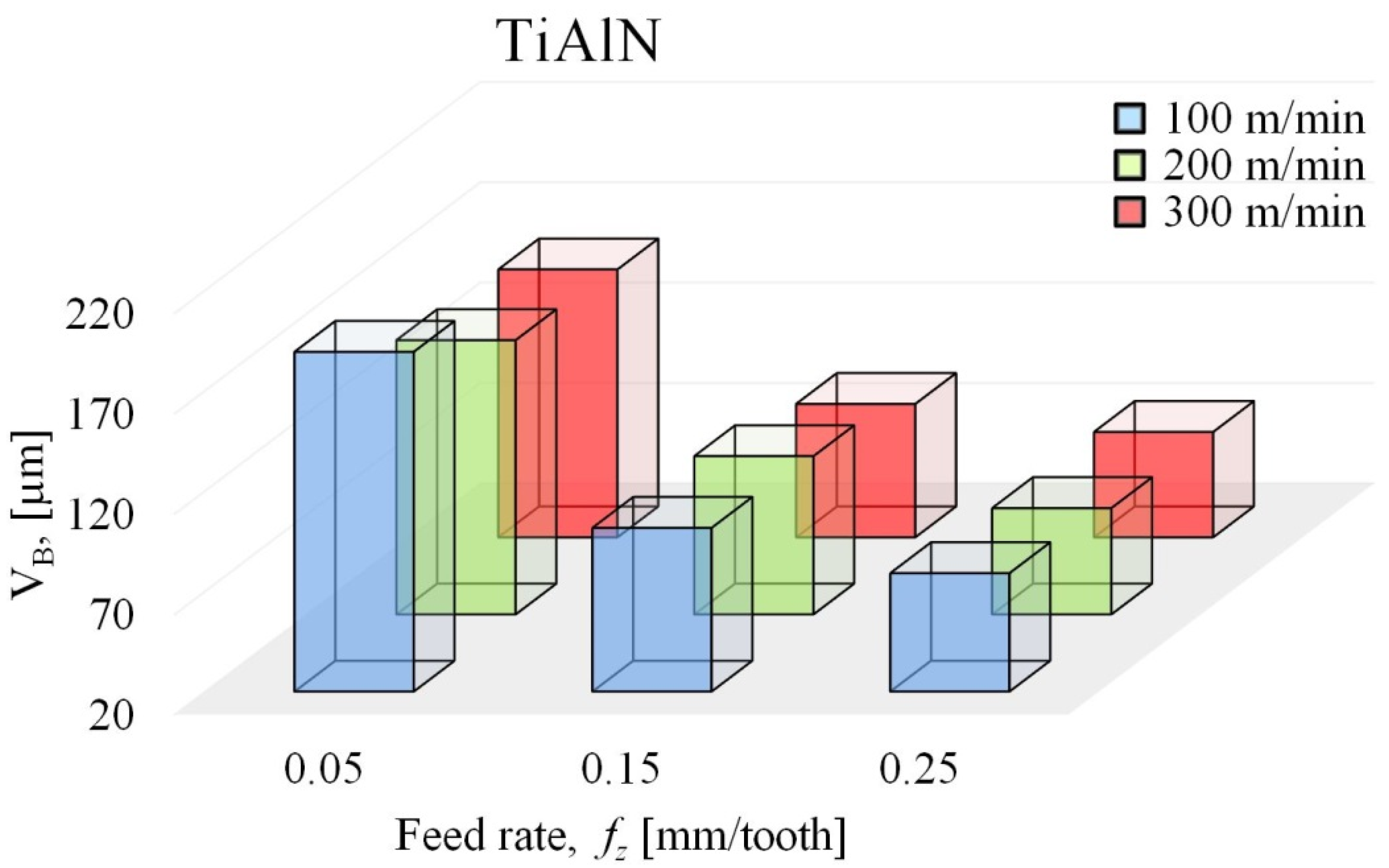
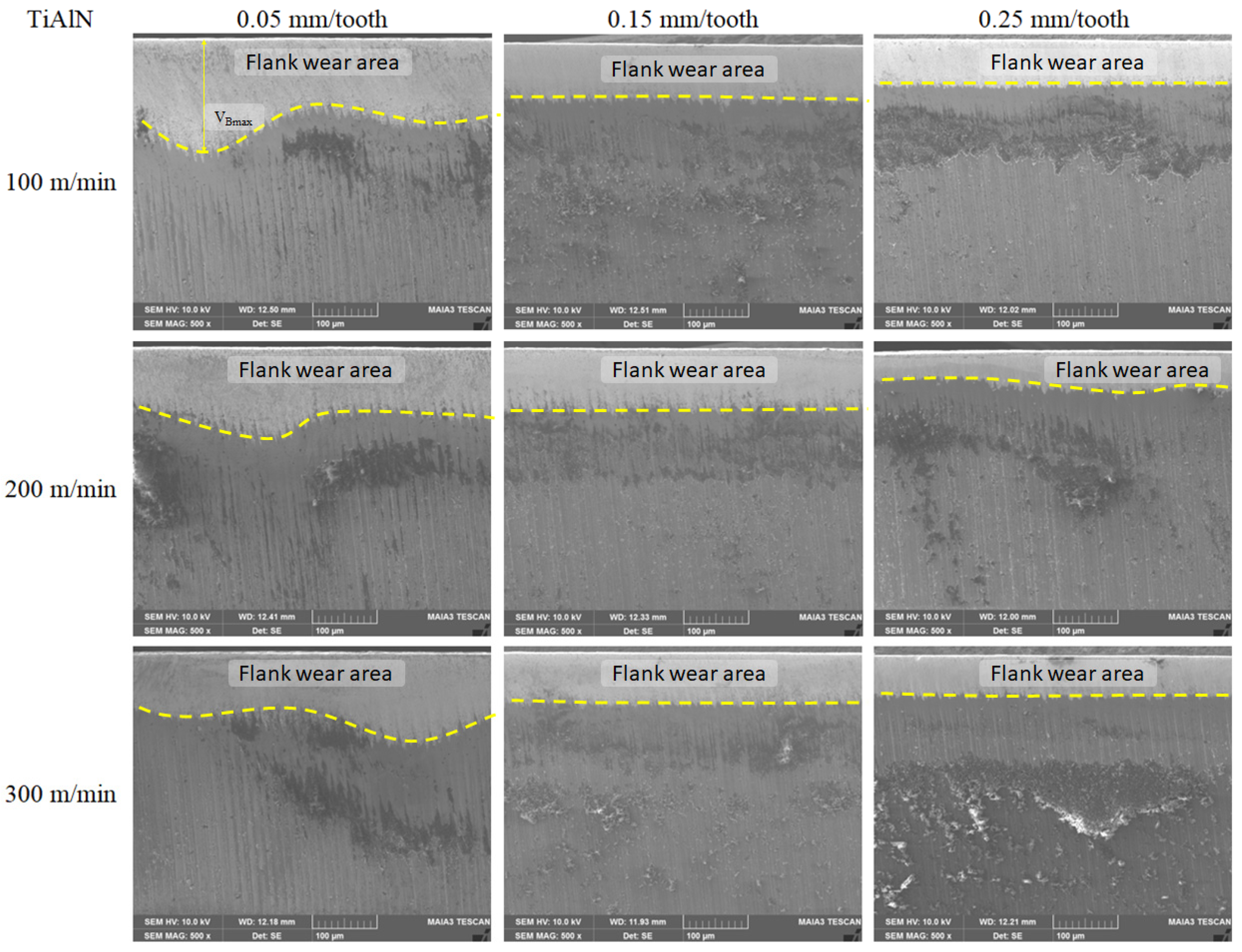
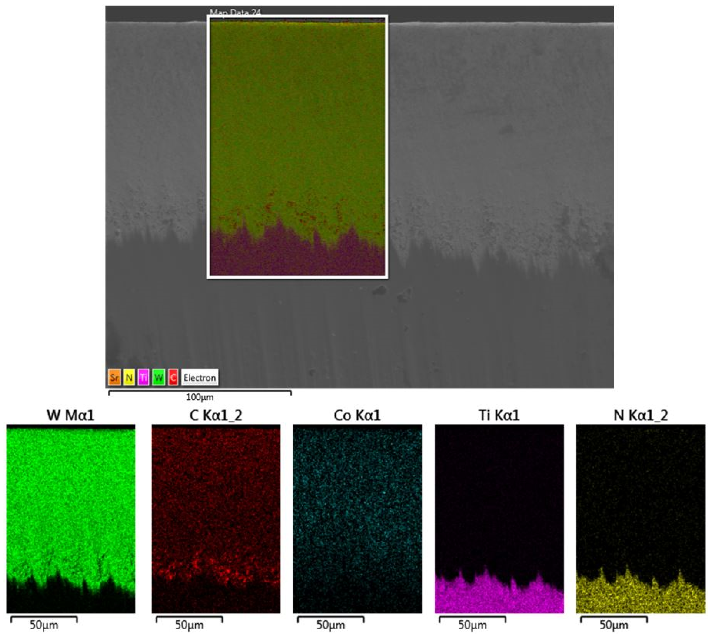
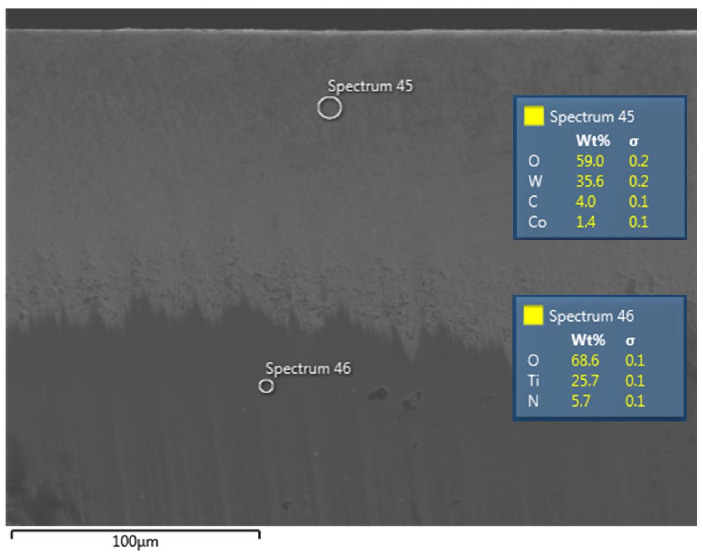
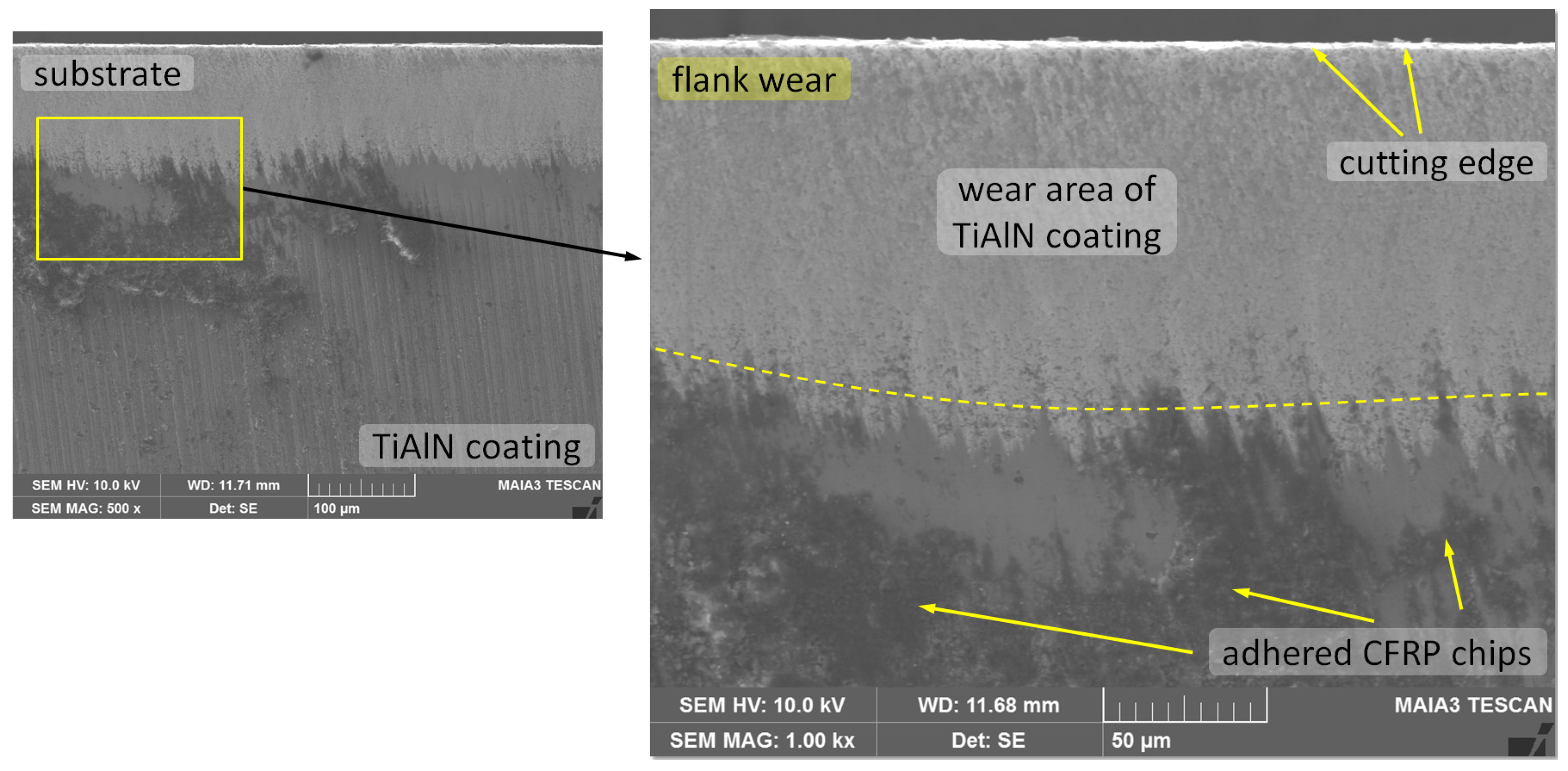
3.1.1. TiAlN-Coated Tools

Figure 2 shows the tool wear on TiAlN-coated tools, generated during the milling of CFRP composite. The resulting wear values (VB) are the maximum values determined from SEM images of the flank face after using the cutting length of 2800 mm (see Figure 3). Due to the inhomogeneous and anisotropic nature of CFRPs, their machining behavior differs in many ways from conventional metal machining, since, for the cutting of CFRPs, tool materials with a high resistance against abrasion are needed. Namely, the flank wear is more strongly affected by the abrasive wear than the cutting energy. At the beginning of the fiber cutting process, a full fiber cut happens; however, the cutting edge becomes more rounded after a certain period. This situation results in flank wear on the cutting tool. Flank wear is the primary tool wear mechanism that develops when machining CFRP composites [32]. During milling, the TiAlN coating has been removed at the cutting edge. This is due to stress concentrations that lead to a cohesive failure in the transient filleted flank cutting wedge region [15]. In addition, the highest wear values were observed at the feed rate of 0.05 mm/tooth (see Figure 3), and it was determined that these values decreased with the increasing feed rate, as shown in Figure 2. This is due to the fact that the tool wear caused by the milling of CFRP depends on the cutting process time [11,33,34]. In the experimental study, the maximum process time of 131.9 s took place with the 0.05 mm/tooth feed rate and the 100 m/min cutting speed. The process times reduced with increased cutting speed and feed rate. The shortest process time was 8.8 s, which happened with the machining parameters of 0.25 mm/tooth feed rate and 300 m/min cutting speed.

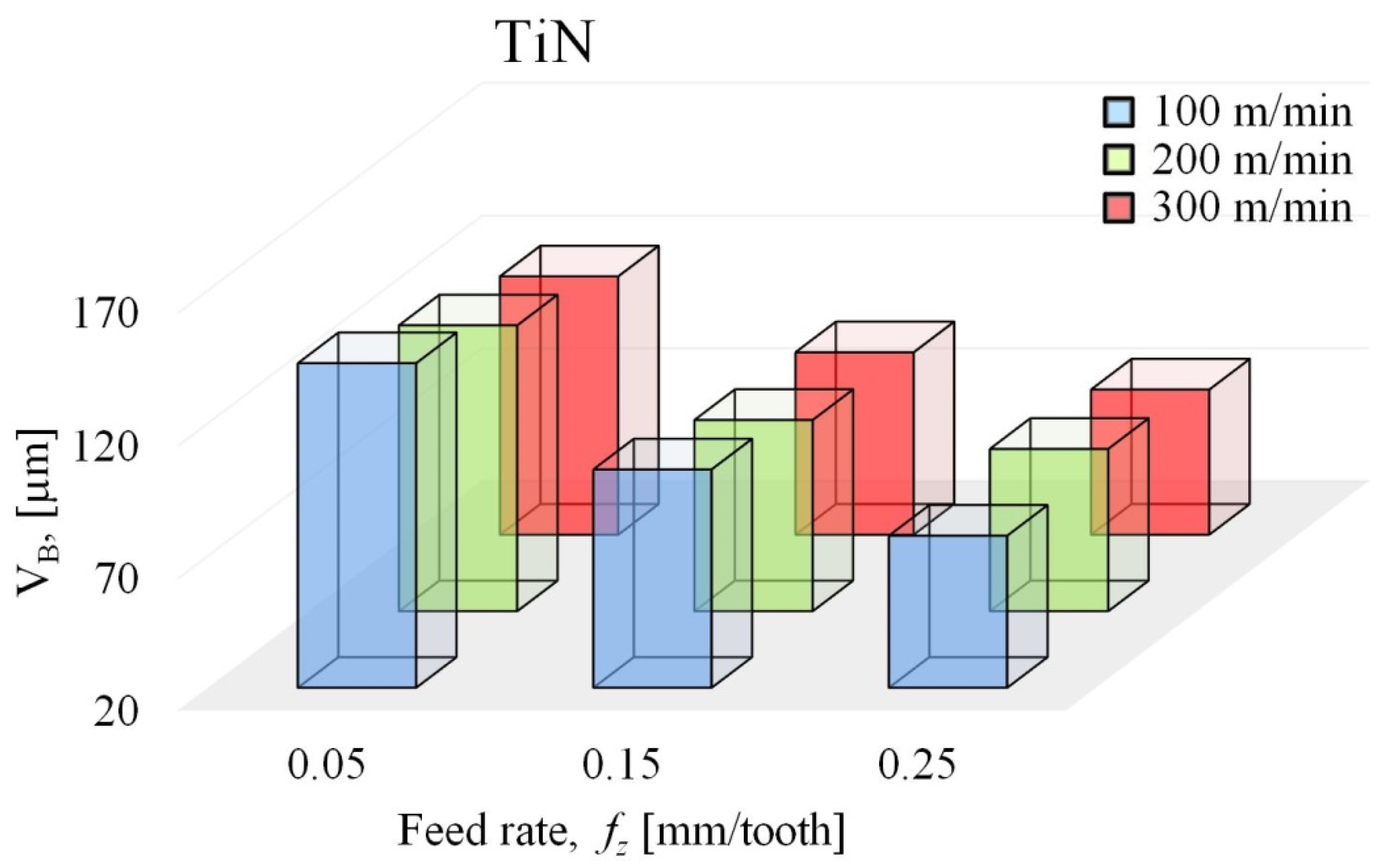
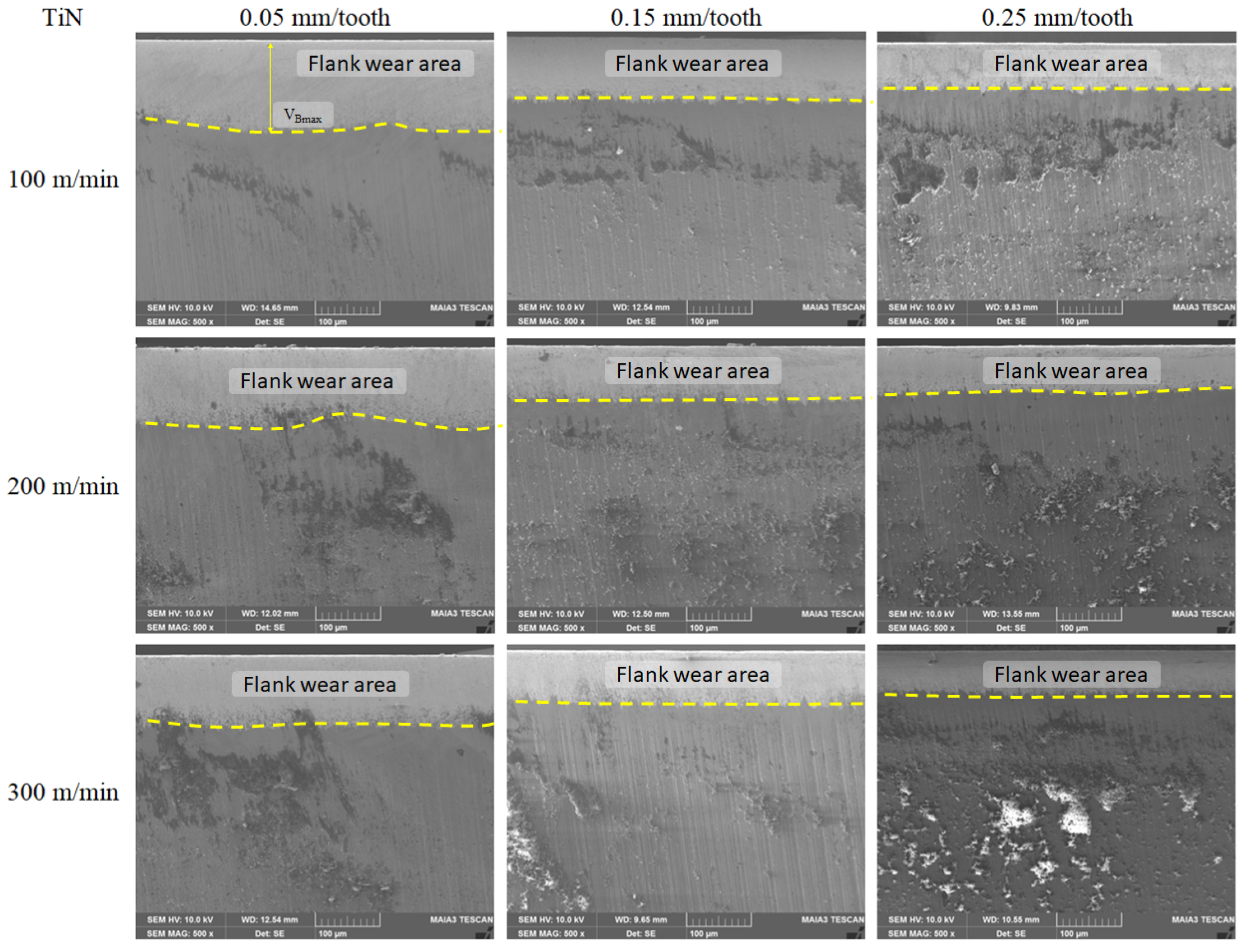
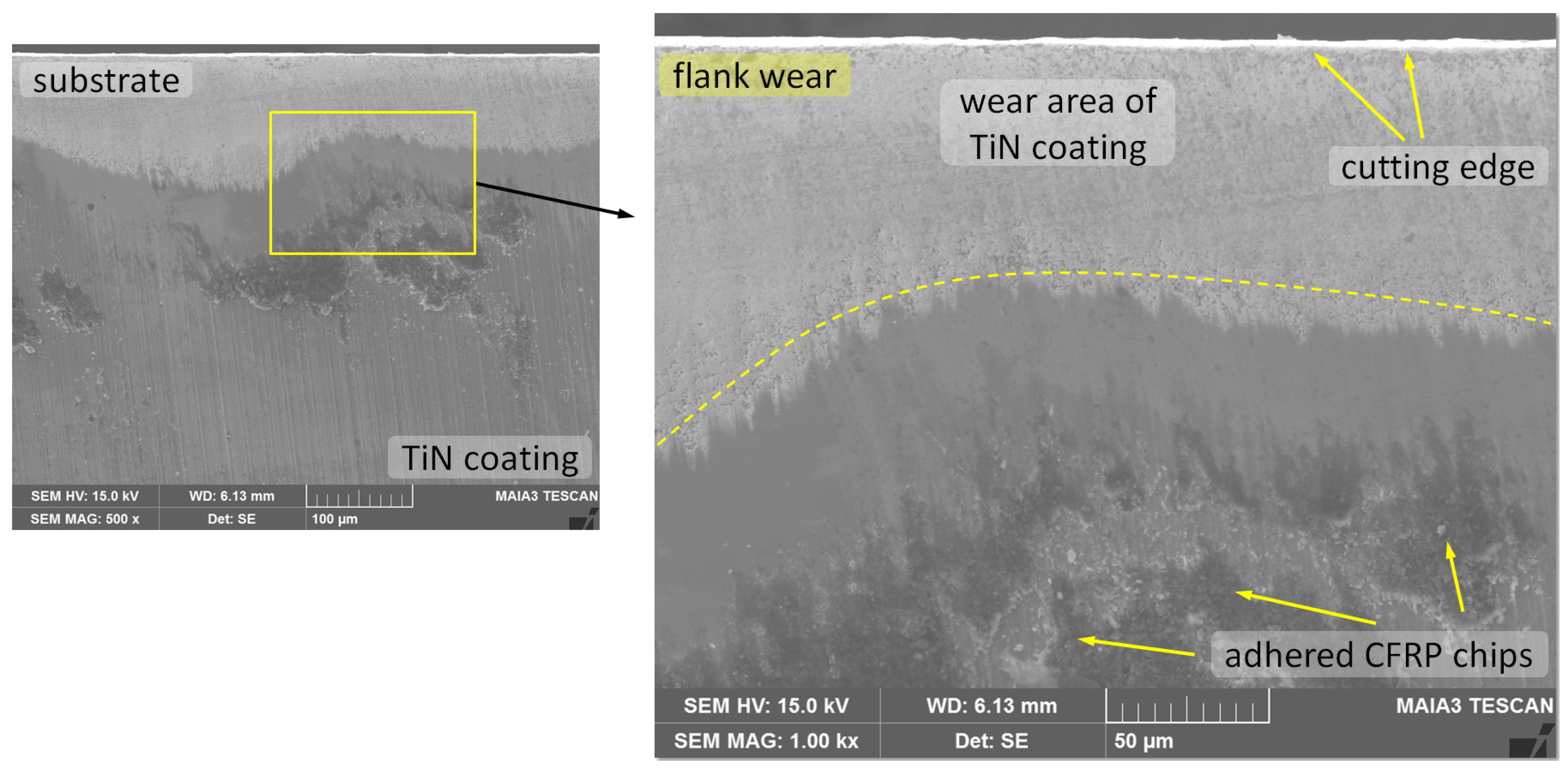
3.1.2. TiN-Coated Tools

Figure 4 shows the tool wear of TiN-coated tools, generated during the milling of the CFRP composite. The resulting wear values are the maximum values determined from SEM images after using the cutting length of 2800 mm (see Figure 5). For the cutting parameters used in this study, the flank wear of the TiN-coated inserts was mainly caused by the abrasion scars on the SEM image of the flank face (see Figure 5). Similar to the case of the TiAlN-coated inserts, the flank wear was also detected on TiN-coated inserts. However, for the 0.05 mm/tooth feed rate, the wear VB values were less, when compared to the TiAlN-coated cutting tool. This can be explained as the TiN coating of the tool acts as a thermal barrier on the cutting tool, and protects the cutting tool from thermal cracking [35]. As a result of the experimental study, it was determined that flank wear values decreased with increasing feed rate. In the milling of CFRPs, the highest flank wear values were measured at the 0.05 mm/tooth feed rate. This wear occurs due to the hard and abrasive structure of carbon fibers [36]. In the case of carbide tools with high toughness properties, the wear on the tool is caused by abrasion, and the best performance in the processing of fiber-reinforced composite materials is achieved by carbide tools [37]. Moreover, Physical Vapor Deposition (PVD) coatings are becoming widespread in applications where sharp cutting edges are required, or in those featuring interrupted cutting operations [38].
The highest wear value (189.30 µm) of the TiAlN- and TiN-coated tools used for milling CFRP materials was found to be no more than the ISO standard’s flank wear criterion: VB = 300 µm [39].

3.2. Analysis of Delamination Damage Mechanism on TiAlN- and TiN-Coated Tools

We investigated the delamination damages of a CFRP work piece during milling at the specified machining parameters, and at different angles of the fiber orientation (0°/45°/90°/−45°). Various delamination damages were observed in the milling of CFRPs with TiAlN- and TiN-coated tools. Delamination or interlaminar crack propagation is one of the most feared damage mechanisms in CFRPs, since it reduces the stiffness and compressive strength of the material, and it is difficult to detect [40]. This is due to the fact that there is no layer to reinforce the work material at the top of the CFRP [22,41]. In the milling of CFRP carried out with coated carbide tools, the main work piece damage is delamination at the edge of the material [21]. During the milling of CFRPs, the cutting tool bends the fibers out and tries to remove them from the layer. This creates stress between layers, and causes the layers to separate from the top [42]. During the machinability test, the work piece should be protected from the damages. However, edge-milling of CFRPs are exposed to delamination due to the abrasive characteristic of this material. Delamination depth (DD) emerges during the edge-milling of CFRP material, and it impairs the quality of machined components. This parameter holds importance in terms of the quality and strength of machined components.
Figure 6 and Figure 7 show the values of delamination depth as a function of cutting speed and feed rate, and SEM images of the delamination of CFRP obtained with the TiAlN-coated tools. The graph includes data measured via SEM images, for different machining parameters and after 2800 mm of chip removal. In our investigation of delamination damage after milling with TiAlN-coated tools, it was found that the values increased with the increasing feed rate (Figure 6), despite decreasing tool wear, which was given in Figure 2. This increase in delamination depth can be caused by the reduced efficiency of milling with the increasing feed rates. Some authors have found that an increase in delamination depth is caused by the edges of the cutting tools that are in more contact with the abrasive structure, which depends on the vibration and increased feed rates [43,44,45]. In the milling of CFRPs, the hardness and strength differences of the matrix and carbon fibers cause rapid changes in the cutting forces, which cause different defects in the transition area [41]. In this study, the highest delamination depth value (310 µm) was obtained with a cutting speed of 200 m/min and a feed rate of 0.25 mm/tooth, while the lowest delamination depth value (94 µm) was obtained with a cutting speed of 300 m/min and feed rate of 0.15 mm/tooth (Figure 7). When milling the CFRP composite with the TiAlN-coated tools at a cutting speed of 100 m/min, the delamination depth values increased by 12% when the 0.05 mm/tooth feed rate was increased by 200%, and the delamination depth values increased by 81.4% when the 0.15 mm/tooth feed rate was increased by 67%. Therefore, it is understandable that the fibers can be cut more easily by keeping the cutting speed at a high level.
Figure 8 and Figure 9 show the values of delamination depth as a function of cutting speed and feed rate, and SEM images of the delamination of CFRP obtained with the TiN-coated tool. The graph includes data measured over SEM images for different machining parameters, and after 2800 mm of chip removal. The work piece behavior during machining with the TiN-coated tool was similar to that for the TiAlN tool. With an increase milling feed rate, the delamination depth increased, and it decreased if the cutting speed increased.
During the machining process, different damages, such as delamination, tool wear, fiber pull-out, fiber breakage and uncut fibers, occur, which all increase the surface roughness. These machining failures can be overcome by selecting the appropriate tool geometry and material. Thus, CFRP composites need to be machined with a sharp tool, otherwise the quality of surface treatment reduces, and the layers of the composite are separated. In the event that the material cannot be completely cut, the cracking and separation of the fibers in the CFRP composite may occur [20]. Figure 10 shows the defects on the CFRP surface that occurred during experiments at high feed rate (0.25 mm/tooth). With the feed rate increased, the amount of material in the cutting tool increases, and this results in a deterioration of the machined surface. Therefore, feed rate is the most significant machining parameter in the milling of CFRPs that affects the roughness. In general, the roughness increases with increasing feed rate [41,46]. Besides, the surface quality is observable directly during and after machining, without the need to damage the CFRP surface to reach the machined surface. Namely, machining quality depends significantly on the machining parameters and cutting tool geometry. During the milling operation, depending on the changing fiber orientation angle, the adhesive interaction between the insert and the CFRP composite also changes. Therefore, the insert interacts with different fiber orientation angles. During the milling experiment on the CFRP composite performed at 0° and 90° fiber orientation angles, the fibers were cut more easily. In consequence, both the CFRP composite and the insert suffered no damage due to the milling process at high speed. Despite this, at ±45° fiber orientation angles, due to the effect of the intense interaction between the insert and the CFRP composite, greater surface damage on the work piece may result. This could be explained via the stacking sequence of different plies in the work piece [47]. Further, regarding tool wear on the cutting tool, it was required to decrease the cutting speed, which also caused lower surface quality. Since the fiber orientation angles at ±45° react to shear loads, the maximum defect is observed during the experiment at these fiber orientation angles [48,49].
In this machinability test, which was applied with TiAlN- and TiN-coated inserts, the wear images were evaluated after milling with specified machining parameters to investigate the wear of the cutting tools. The wear images given in Figure 3 and Figure 5 are taken from the center of the cutting tools after using a cutting length of 10 mm. Milling was carried out 6-mm thick CFRP, so that the contact points of the cutting tool were 2 mm above and 2 mm below. Figure 11 shows the summary of this condition clearly.
Due to the frictional heating, during the milling of the CFRP composite, the flank wear of the cutting tools was observed. The presence of the hard, abrasive fiber inside the matrix of the CFRP composite causes the abrasion of the cutting tools. Tool wear directly affects the surface quality of the machined parts [50]. Due to the highly abrasive nature of the carbon fibers and the low thermal conductivity of the matrix resin, rapid tool wear can occur even if diamond-coated carbide and multi crystalline diamond cutting tools are used, because the laminated structure and layers are exposed to separation as a result of the cutting forces that take place during machining. We can explain this phenomenon via the fact that during the milling experiment, the surface fibers are bent by the cutting force. Due to a lack of external support, the fibers are rebounded under the cutting force [40]. Tool wear can be kept under control with increasing cutting forces. Therefore, tool wear is very significant during the milling of CFRPs, because if cutting forces increase tool wear increases. The consequence of this is delamination, which is an undesirable damage mechanism in CFRPs machining [51]. Thus, the delamination, machining accuracy and surface quality are directly related to tool wear. Furthermore, the mechanical resistance of carbon fibers is highly related to tool wear [52]. In their study, Hintze et al. attributed the increase of delamination to the increase in the cutting edge radius of PCD tool, because the rounded cutting edge increases the cutting forces [53]. Moreover, when the cutting temperature increases, the delamination depth can also increase, due to the degradation of the resin used in CFRP [54].
The highest values of flank wear increased in the low processing conditions (100 m/min and 0.05 mm/tooth). Under low machining conditions, the cutting operation took place over the longest time (131.9 s) to remove the chip from the CFRP composite. During the chip removal process, the cutting tools remained continuously in contact with the hard and abrasive fiber materials. Due to the increased interaction at the tool–work piece interface over the long processing period, the tool wear value was also increased. With increases in the machining parameter values, tool wear rates were decreased, due to the decreasing time of interaction (Figure 2 and Figure 4). In the case of, the machining done at high processing conditions (300 m/min and 0.25 mm/tooth), the interaction time was only 8.8 s, and the lowest tool wear values were found. EDS and elemental mapping images taken from the worn surfaces of TiAlN- and TiN-coated tools are given in Figure 12, Figure 13, Figure 14 and Figure 15. The EDS and elemental mapping images have shown that the depth of the surface area was widened, up to 100 µm. The average surface area variations and effect can be observed from the figures.
The selection of the cutting tool materials and machining parameters are largely determined by the properties of the CFRPs. Due to the specific structural properties of CFRPs, milling is used for shaping parts made of these materials, but some unwanted damages occur because this process is discontinuous. Delamination, which is one of these damages, depend on the component of cutting force normal to the stacking plane in uni/multi directional laminate composites [9]. The delamination damage, which may happen during the milling process of CFRP, is a failure mechanism that results in the impaired quality of machined components. As a result of the study, it was observed that the delamination depth obtained with both coated cutting tools did not exceed 1.5 mm (1500 µm), which is the acceptance limit in the aviation industry [40,55]. The highest value of delamination depth (310 µm) was obtained with the 200 m/min cutting speed and the 0.25 mm/tooth feed rate, for the TiAlN-coated tool. The lowest value (80 µm) was measured for the TiN-coated tool operated at a cutting speed of 300 m/min and a feed rate of 0.05 mm/tooth. In their study, Sheikh-Ahmad et al. reported on edge trimming operations of CFRPs, and they obtained the best surface quality at high cutting speeds and low feed rates [22]. According to the delamination damage mechanism, it was found that the machining of CFRP composites was better at the high cutting speeds and low feed rates. In their study, Xu et al. found similar results that support this condition [56].
The CFRP is reinforced with carbon fiber bonded with epoxy adhesive. Its structure is not uniform, so it is difficult to machine. Therefore, the choice of the cutting tool and the optimum machining parameters are very significant during milling. Since the tool tip does not actually cut into the work piece, but applies a pressure on it, this results in a series of failures, such as delamination, delamination depth, etc. [57]. The tool is worn seriously during the milling, and its life is reduced. The high tool wear and poor surface finish of the work piece result in a poor-quality work piece. CFRP could not cut the fibers completely due to the insufficient layer-thickness during the machining. Due to the insufficient layer-thickness during the machining of CFRP, the TiN-coated tool could not cut the fibers completely. This was because the corner radii of the cutting edges are more rounded. The corner radii of the TiAlN-coated tool are sharper.
In order to better analyze the delamination depth of CFRP, the SEM investigations of the wear zones of TiAlN- and TiN-coated tools, as well as the coating–substrate interface, were performed. We found that the transition regions have different profiles. Typical examples are shown in Figure 16 and Figure 17. It is thought that these transition regions, which play an important role in the cutting process together with other parameters, have an effect on delamination damage. Unlike the TiAlN-coated tool, the interface profile of the TiN-coated tool showed that the wear is large and fluctuating. This could be due to the thickness of the coating layer, and the property of having the lowest adhesion. It was observed that the widths of the tooth-shaped profile formed in this area for the TiAlN-coated tool were 20 and 25 µm. In some regions, where this value changes, it has been observed that it is further narrowed, while the end parts were sharpened. This situation may be explained via the higher hardness of TiAlN coatings [58].

4. Conclusions

Surface damages to CFRP work piece materials, such as burrs, fiber fractures and the delamination formed during milling, are significant to the quality of the machining process. In the present article, the tool wear and work piece damage mechanisms in unidirectional CFRP composites used in milling processes were investigated. Additionally, according to experimental observation, the formation mechanism of the delamination depth is also analyzed. The salient features and innovative outcomes of this study have been drawn beneath:
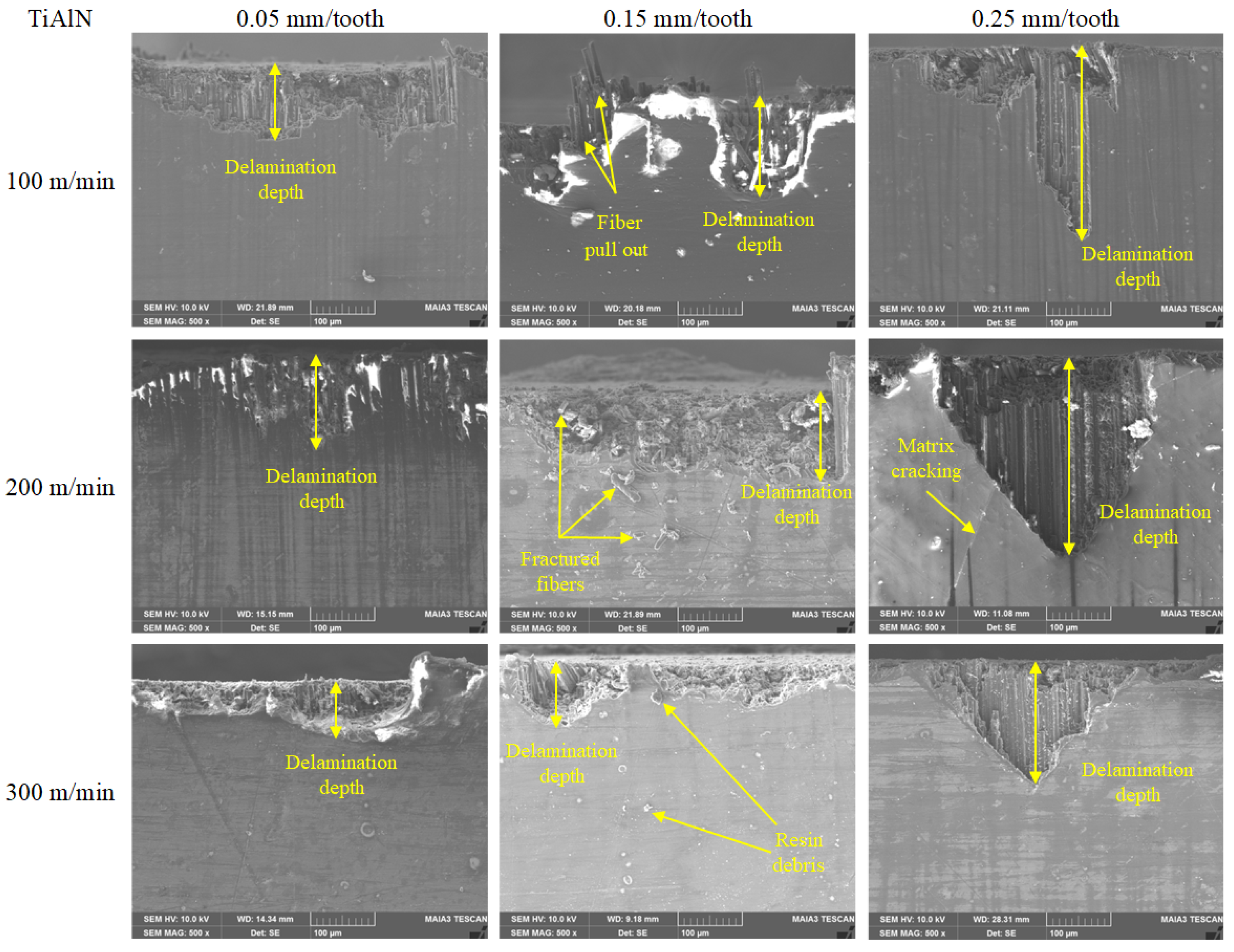
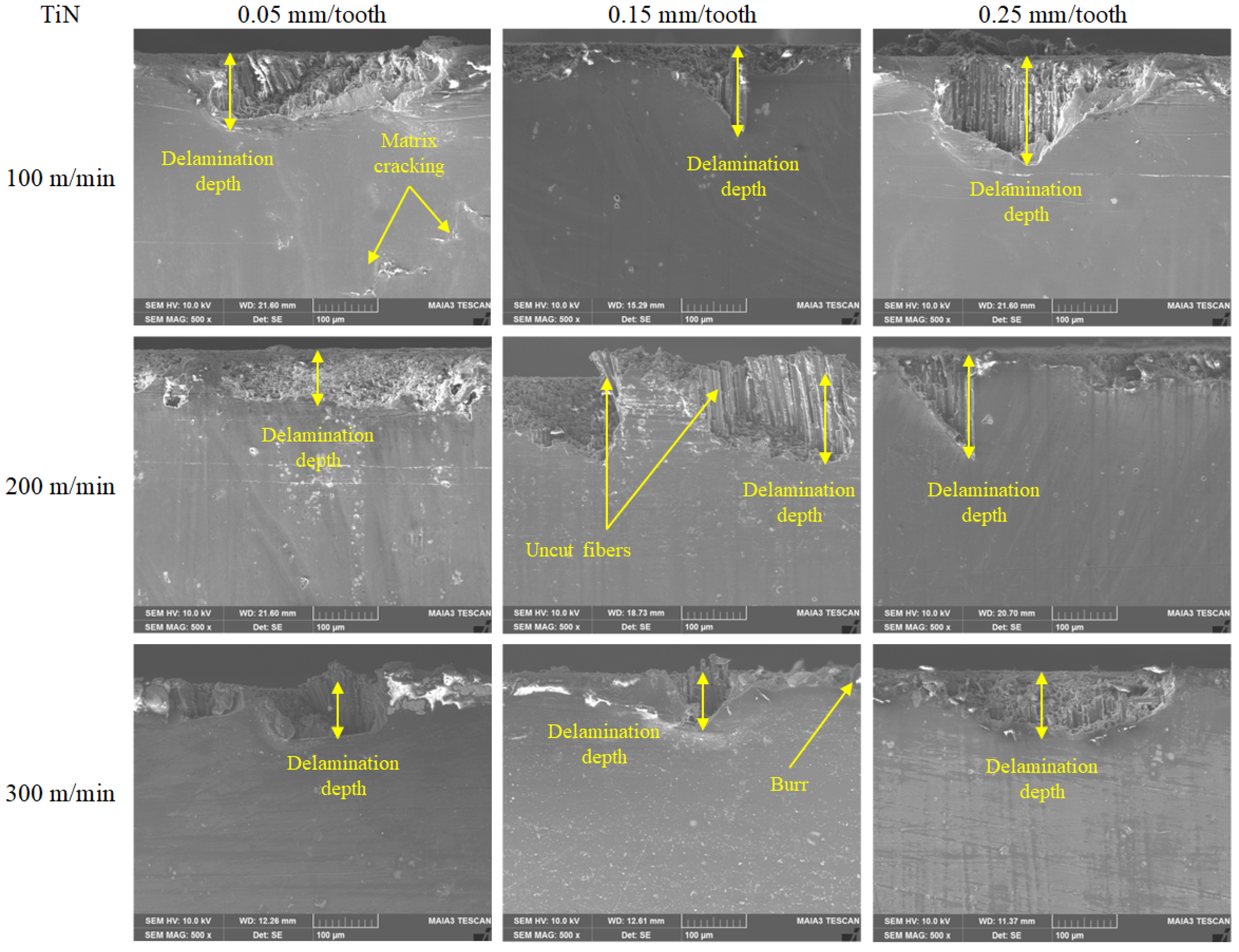
  • As reported in various studies, failures, such as delamination, tool wear, fiber pull-out, uncut fibers and thermal damage, occur during the machining of CFRPs. When compared with other related works, such in-depth microstructural investigation of these failures has been carried out for the first time in the present study.
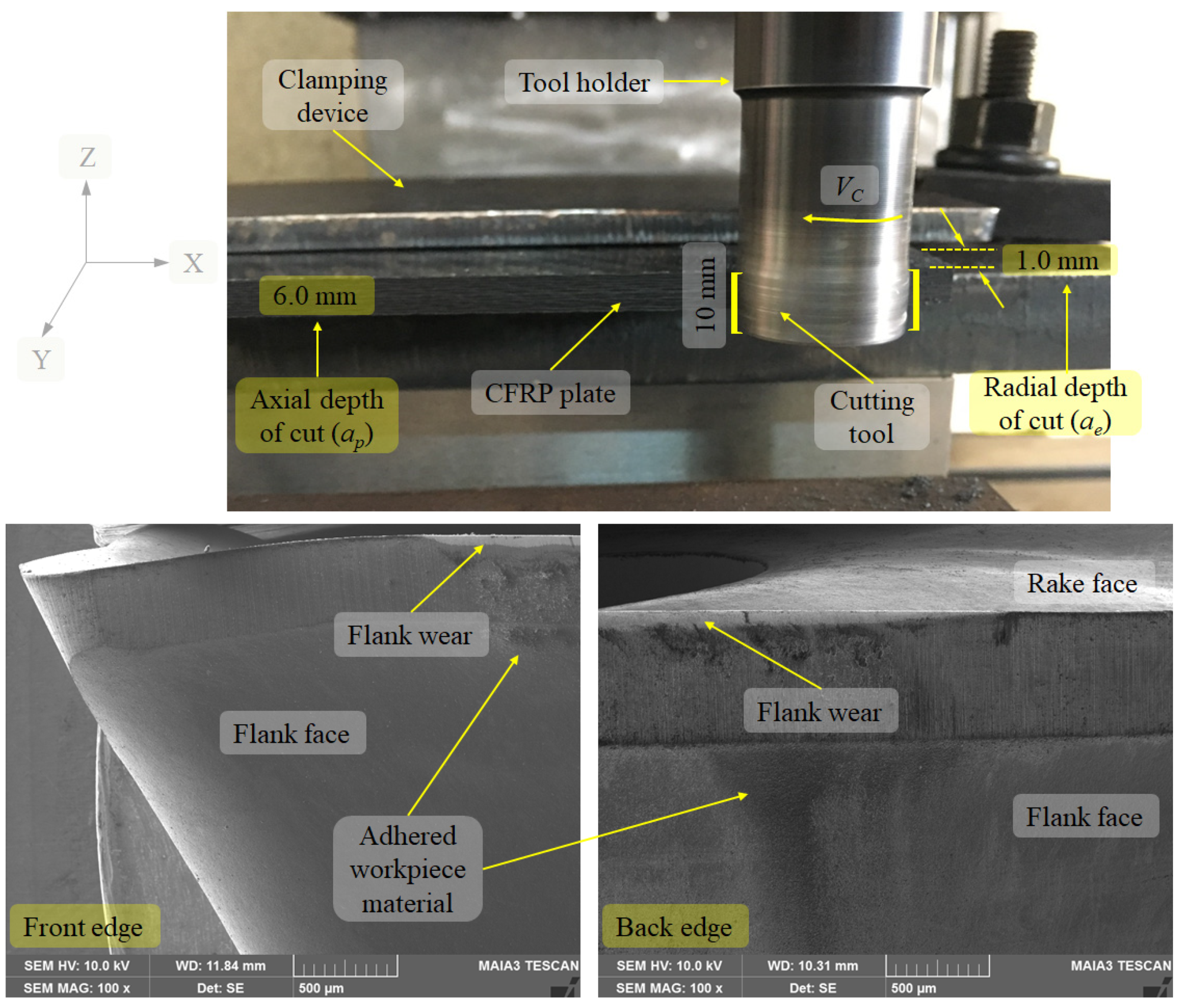
  • During the milling operations, the wear VB arising from the abrasive characteristic of CFRP composites was detected on TiAlN- and TiN-coated tools. According to the wear results, the highest wear value (189.30 µm) was obtained on the TiAlN-coated tool, at a 0.05 mm/tooth feed rate and a 100 m/min cutting speed. The lowest wear value (72.50 µm) was obtained on the TiAlN-coated tool at a 0.25 mm/tooth feed rate and a 300 m/min cutting speed. For the 0.05 mm/tooth feed rate, the wear VB values were lower when compared to the TiAlN-coated cutting tool.
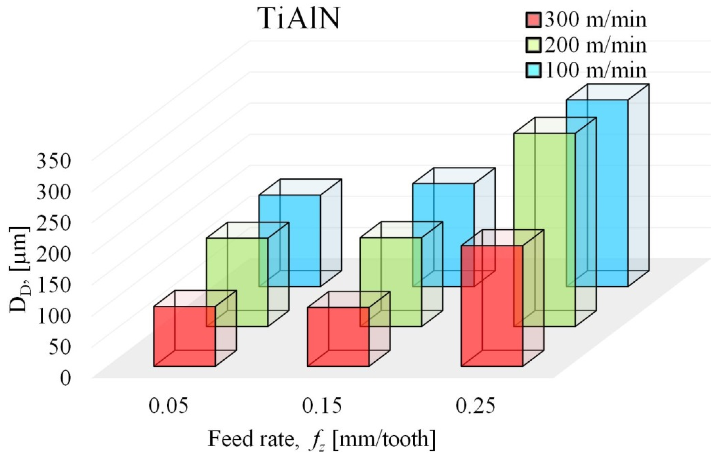
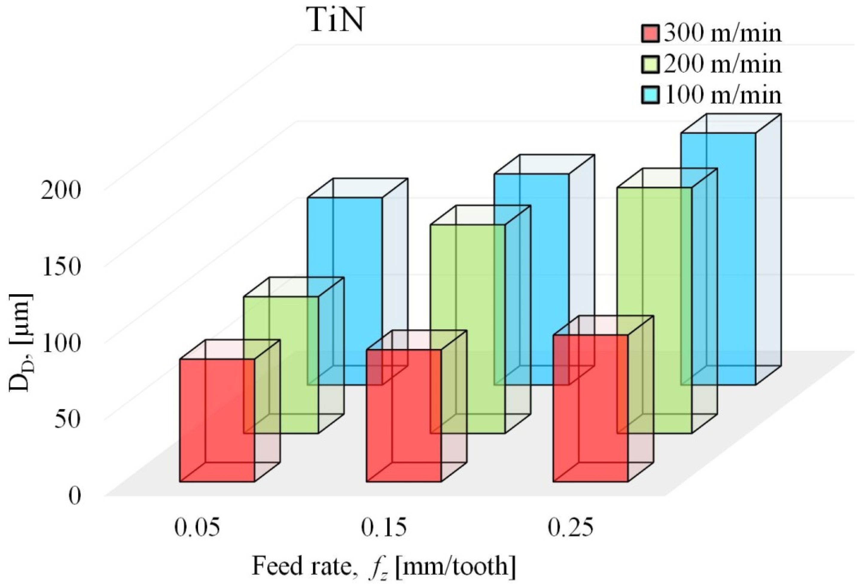
  • In the milling of CFRP composites with TiAlN- and TiN-coated tools, the delamination depth increases depending on the feed rates, due to the abrasive, heterogeneous structure of the material, and its resistance against plastic deformation. The results obtained for varying feed rates show that the best results were obtained with a 0.15 mm/tooth feed rate and a delamination depth value of 86.21 µm, used on the TiN-coated tool. The highest delamination depth value of 310.41 µm was obtained on the TiAlN-coated tool at 0.25 mm/tooth feed rate. Feed rate was found to be the most influential parameter in the machining of CFRP materials. All delamination depth results for the CFRP composite materials, obtained after milling with coated cutting tools, remained under the accepted limit in the aviation industry.
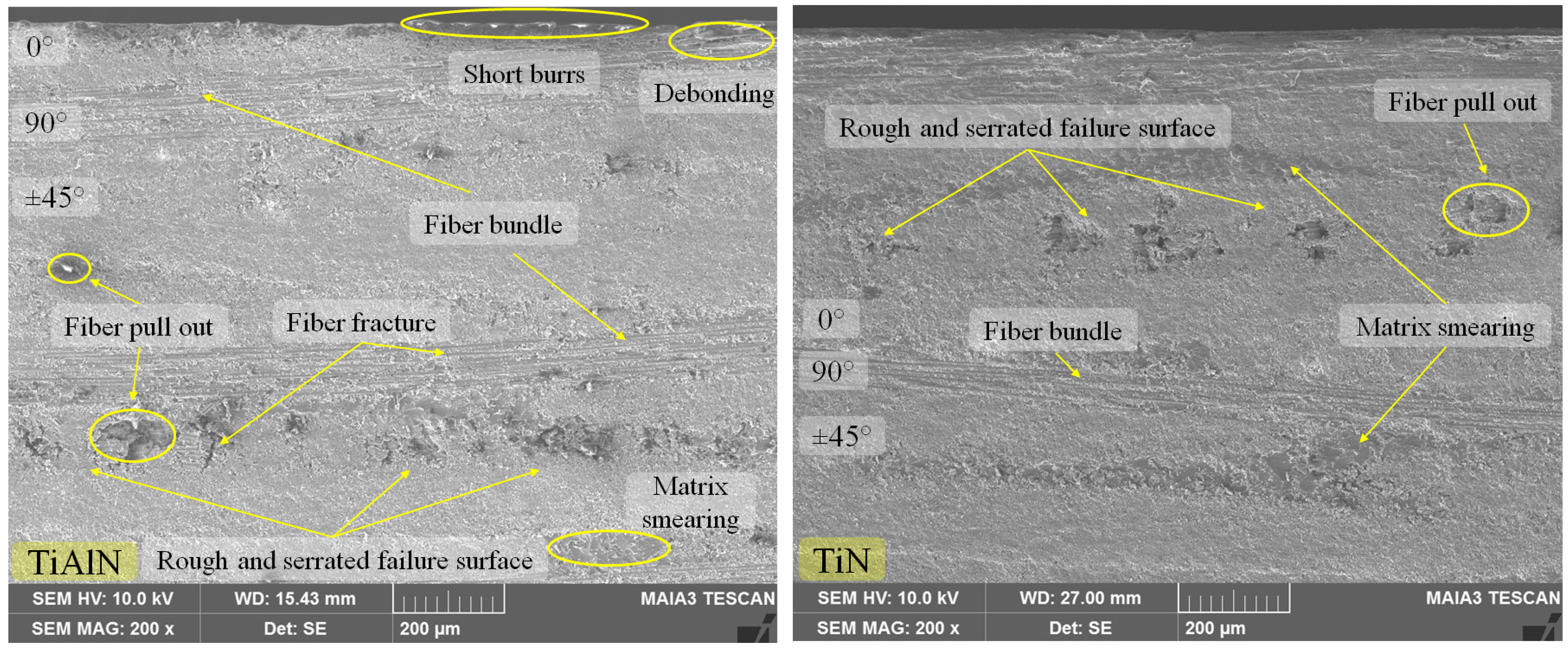
  • The defects on the CFRP’s surface occurred during experiments at high feed rates (0.25 mm/tooth). With the feed rate increases, the amount of material in the cutting tool increases, and this results in a deterioration of the machined surface.
  • In terms of fiber orientation angles, at 0° and 90° orientation the work piece material and the cutting tool did not suffer any damage. On the other hand, at ±45° fiber orientation angles, higher surface damage was observed during milling.
  • SEM images at the delamination depth showed the influence of parameters on surface damage. Each feed rate caused a different damage; in particular, high cutting speeds led to more visual damages. Thus, the increase of the amount of material on the cutting tool results in the deterioration of the machined surface.

Author Contributions

Performed and designed the experiments, D.O., and M.S.G.; verification experiments and wrote the paper, D.O., and A.C.K.; revised the paper and supervised the whole research, D.O., P.P., and A.C.K.; analyzed the data, D.O., A.C.K., M.S.G., and P.P. All authors have read and agreed to the published version of the manuscript.

Funding

This work was financially supported by Scientific Research Projects (BAP) of Bartin University with project code of 2016-FEN-C-004.

Acknowledgments

The authors thank Jožef Stefan Institute for their support in the preparation of the coatings.

Conflicts of Interest

The authors declare no conflict of interest.

References

  1. Nguyen-Dinh, N.; Hejjaji, A.; Zitoune, R.; Bouvet, C.; Salem, M. New tool for reduction of harmful particulate dispersion and to improve machining quality when trimming carbon/epoxy composites. Compos. Part A Appl. Sci. Manuf. 2020, 131, 105806. [Google Scholar] [CrossRef]
  2. Nguyen-Dinh, N.; Bouvet, C.; Zitoune, R. Influence of machining damage generated during trimming of CFRP composite on the compressive strength. J. Compos. Mater. 2020, 54, 1413–1430. [Google Scholar] [CrossRef]
  3. Tsokanas, P.; Loutas, T.; Nijhuis, P. Interfacial Fracture Toughness Assessment of a New Titanium–CFRP Adhesive Joint: An Experimental Comparative Study. Metals 2020, 10, 699. [Google Scholar] [CrossRef]
  4. Babu, G.D.; Babu, K.S.; Gowd, B.U.M. Effect of machining parameters on milled natural fiber-reinforced plastic composites. J. Adv. Mech. Eng. 2013, 1, 1–12. [Google Scholar] [CrossRef]
  5. Mazumdar, S.K. Composites Manufacturing: Materials, Product, and Process Engineering, 1st ed.; CRC Press: Boca Raton, NY, USA, 2001; pp. 99–149. [Google Scholar]
  6. Mallick, P.K. Fiber-Reinforced Composites: Materials, Manufacturing, and Design, 3rd ed.; Taylor and Francis: New York, NY, USA, 2008; pp. 64–71. [Google Scholar]
  7. Gay, D.; Hoa, S.V.; Tsai, S.W. Composite Materials, Design and Applications, 3rd ed.; CRC Press: New York, NY, USA, 2003. [Google Scholar]
  8. Deborah, D.C. Carbon Fiber Composites, 1st ed.; Butterworth-Heinemann Publisher: Boston, MA, USA, 1994. [Google Scholar]
  9. Devi, K.; Sheikh-Ahmad, J.; Twomey, J. Prediction of cutting force s in helical end milling fiber reinforced polymers. Int. J. Mach. Tools Manuf. 2010, 50, 882–891. [Google Scholar]
  10. Jahanmir, S.; Ramulu, M.; Koshy, P. Machining of Ceramics and Composites; Marcel Dekker: New York, NY, USA, 1999. [Google Scholar]
  11. Iliescu, D.; Gehin, D.; Gutierrez, M.E.; Girot, F. Modeling and Tool Wear in Drilling of CFRP. Int. J. Mach. Tools Manuf. 2010, 50, 204–213. [Google Scholar] [CrossRef]
  12. Marques, A.T.; Durao, L.M.; Magalhaes, A.G.; Silva, J.F.; Tavares, J.M.R.S. Delamination analysis of carbon fibre reinforced laminates: Evaluation of a special step drill. Compos. Sci. Technol. 2009, 69, 2376–2382. [Google Scholar] [CrossRef] [Green Version]
  13. Chardon, G.; Klinkova, O.; Rech, J.; Drapier, S.; Bergheau, J.M. Characterization of friction properties at the work material/cutting tool interface during the machining of randomly structured carbon fibers reinforced polymer with carbide tools under dry conditions. Tribol. Int. 2011, 81, 300–308. [Google Scholar] [CrossRef]
  14. Dandekar, C.R.; Shin, Y.C. Modeling of machining of composite materials: A review. Int. J. Mach. Tools Manuf. 2012, 57, 102–121. [Google Scholar] [CrossRef]
  15. Hocheng, H.; Puw, H.Y.; Huang, Y. Preliminary study on milling of unidirectional carbon fibre-reinforced plastics. Compos. Manuf. 1993, 4, 103–108. [Google Scholar] [CrossRef]
  16. Kiliçkap, E.; Yardimeden, A.; Yahya, Ç.H. Investigation of experimental study of end milling of CFRP composite. Sci. Eng. Compos. Mater. 2015, 22, 89–95. [Google Scholar] [CrossRef]
  17. Dold, C.; Henerichs, M.; Bochmann, L.; Wegener, K. Comparison of ground and laser machined polycrystalline diamond (PCD) tools in cutting carbon fiber reinforced plastics (CFRP) for aircraft structures. Procedia CIRP 2012, 1, 178–183. [Google Scholar] [CrossRef]
  18. Ozkan, D.; Panjan, P.; Gok, M.S.; Karaoglanli, A.C. Investigation of machining parameters that affects surface roughness and cutting forces in milling of CFRPs with TiAlN and TiN coated carbide cutting tools. Mater. Res. Express 2019, 6, 095616. [Google Scholar] [CrossRef]
  19. Rech, J. Influence of cutting tool coatings on the tribological phenomena at the tool–chip interface in orthogonal dry turning. Surf. Coat. Technol. 2006, 200, 5132–5139. [Google Scholar] [CrossRef]
  20. Bhatnacar, N.B.; Ramakrishnan, N.; Naik, N.K.; Komanduri, R.B. On the Machining of Fiber Reinforced Plastic (FRP) Composite Laminates. Int. J. Mach. Tools Manuf. 1995, 35, 701–716. [Google Scholar] [CrossRef]
  21. Davim, J.P.; Reis, P. Damage and dimensional precision on milling carbon fiber-reinforced plastics using design experiments. J. Mater. Process. Technol. 2005, 160, 160–167. [Google Scholar] [CrossRef]
  22. Sheikh-Ahmad, J.; Urban, N.; Cheraghi, H. Machining Damage in Edge Trimming of CFRP. Mater. Manuf. Process. 2012, 27, 802–808. [Google Scholar] [CrossRef]
  23. Wang, H.; Qin, X.; Li, H. Machinability analysis on helical milling of carbon fiber reinforced polymer. J. Adv. Mech. Des. Syst. Manuf. 2015, 9, 1–11. [Google Scholar] [CrossRef] [Green Version]
  24. Ucar, M.; Wang, Y. End-milling machinability of a carbon fiber reinforced laminated composite. J. Adv. Mater. 2005, 37, 46–52. [Google Scholar]
  25. Isbilir, O.; Ghassemieh, E. Delamination and wear in drilling of carbon-fiber reinforced plastic composites using multilayer TiAlN/TiN PVD-coated tungsten carbide tools. J. Reinf. Plast. Compos. 2012, 31, 717–727. [Google Scholar] [CrossRef]
  26. Hocheng, H.; Tsao, C.C. The path towards delamination-free drilling of composite materials. J. Mater. Process. Technol. 2005, 167, 251–264. [Google Scholar] [CrossRef]
  27. Khashaba, U. Delamination in drilling GFR-thermoset composites. Compos. Struct. 2004, 63, 313–327. [Google Scholar] [CrossRef]
  28. Advanced Composite Materials-Chapter 7. Available online: https://www.faa.gov/regulations_policies/handbooks_manuals/aircraft/media/amt_airframe_hb_vol_1.pdf (accessed on 22 June 2020).
  29. ISO 1832. Indexable inserts for cutting tools–Designation; International Standards Organization (ISO): Geneva, Switzerland, 1991. [Google Scholar]
  30. ISO 5608. Turning and copying tool holders and cartridges for indexable inserts-Designation; International Organization for Standardization (ISO): Geneva, Switzerland, 1995. [Google Scholar]
  31. An, Q.; Ming, W.; Cai, X.; Chen, M. Study on the cutting mechanics characteristics of high-strength UD-CFRP laminates based on orthogonal cutting method. Compos. Struct. 2015, 131, 374–383. [Google Scholar] [CrossRef]
  32. Cadorin, N.; Zitoune, R. Wear signature on hole defects as a function of cutting tool material for drilling 3D interlock composite. Wear 2015, 332, 742–751. [Google Scholar] [CrossRef]
  33. Nor Khairusshima, M.K.; Hassan, C.C.; Jaharah, A.G.; Na, A.K.M. Tool Wear and Surface Roughness on Milling Carbon Fiber-reinforced Plastic using Chilled Air. J. Asian Sci. Res. 2012, 2, 593. [Google Scholar]
  34. Samy, G.S.; Kumaran, S.T.; Uthayakumar, M. An analysis of end milling performance on B4C particle reinforced aluminum composite. J. Aust. Ceram. Soci. 2017, 53, 373–383. [Google Scholar] [CrossRef]
  35. Madhavan, V.; Lipczynski, G.; Lane, B.; Whitenton, E. Fiber orientation angle effects in machining of unidirectional CFRP laminated composites. J. Manuf. Process. 2015, 20, 431–442. [Google Scholar] [CrossRef] [Green Version]
  36. Seid Ahmed, Y.; Paiva, J.M.; Covelli, D.; Veldhuis, S.C. Investigation of coated cutting tool performance during machining of super duplex stainless steels through 3D wear evaluations. Coatings 2017, 7, 127. [Google Scholar] [CrossRef] [Green Version]
  37. Sheikh-Ahmad, J.Y. Machining of Polymer Composites; Springer: New York, NY, USA, 2009. [Google Scholar]
  38. Sahin, M.; Misirli, C.; Ozkan, D. Characteristic properties of AlTiN and TiN coated HSS materials. Ind. Lubr. Tribol. 2015, 67, 172–180. [Google Scholar] [CrossRef]
  39. ISO 8688-2. International Standard for Tool Life Testing in End Milling—Part 2, 1st ed.; International Standard Organization: Geneva, Switzerland, 1989. [Google Scholar]
  40. Tamin, M.N. Damage and Fracture of Composite Materials and Structures; Springer: Heidelberg, Germany, 2012. [Google Scholar]
  41. Liu, G.; Chen, H.; Huang, Z.; Gao, F.; Chen, T. Surface Quality of Staggered PCD End Mill in Milling of Carbon Fiber Reinforced Plastics. Appl. Sci. 2017, 7, 199. [Google Scholar] [CrossRef]
  42. Hintze, W.; Hartmann, D. Modeling of delamination during milling of unidirectional CFRP. Procedia CIRP 2013, 8, 444–449. [Google Scholar] [CrossRef] [Green Version]
  43. Nurhaniza, M.; Ariffin, M.K.; Mustapha, F.; Baharudin, B.T. Analyzing the effect of machining parameters setting to the surface roughness during end milling of CFRP-Aluminium composite laminates. Int. J. Manuf. Eng. 2016, 2016, 1–9. [Google Scholar] [CrossRef]
  44. Kecik, K.; Rusinek, R.; Warminski, J.; Weremczuk, A. Chatter control in the milling process of composite materials. J. Phys. Conf. Ser. 2012, 382, 012012. [Google Scholar] [CrossRef] [Green Version]
  45. Ozkan, D.; Gok, M.S.; Gokkaya, H.; Karaoglanli, A.C. Machining effects on delamination failure in milling MD-CFRPs with uncoated carbide tools. Emerg. Mater. Res. 2019, 8, 1–13. [Google Scholar] [CrossRef]
  46. Wang, H.; Sun, J.; Li, J.; Li, W. Roughness modelling analysis for milling of carbon fibre reinforced polymer composites. Mater. Technol. 2015, 30, A46–A50. [Google Scholar] [CrossRef]
  47. Zitoune, R.; Collombet, F.; Lachaud, F.; Piquet, R.; Pasquet, P. Experiment–calculation comparison of the cutting conditions representative of the long fiber composite drilling phase. Compos. Sci. Technol. 2005, 65, 455–466. [Google Scholar] [CrossRef]
  48. Oliveria, T.L.L.; Zitoune, R.; Ancelotti, A.C., Jr.; da Cunha, S.S., Jr. Smart machining: Monitoring of CFRP Milling using AE and IR. Compos. Struct. 2020, 112611. [Google Scholar] [CrossRef]
  49. Cadorin, N.; Zitoune, R.; Seitier, P.; Collombet, F. Analysis of damage mechanism and tool wear while drilling of 3D woven composite materials using internal and external cutting fluid. J. Compos. Mater. 2014, 49, 2687–2703. [Google Scholar] [CrossRef]
  50. An, Q.; Wang, C.; Xu, J.; Liu, P.; Chen, M. Experimental investigation on hard milling of high strength steel using PVD-AlTiN coated cemented carbide tool. Int. J. Refract. Met. Hard Mater. 2014, 43, 94–101. [Google Scholar] [CrossRef]
  51. Karpat, Y.; Bahtiyar, O.; Deger, B. Mechanistic force modeling for milling of unidirectional carbon fiber reinforced polymer laminates. Int. J. Mach. Tools Manuf. 2012, 56, 79–93. [Google Scholar] [CrossRef]
  52. Slamani, M.; Chatelain, J.F.; Hamedanianpour, H. Comparison of two models for predicting tool wear and cutting force components during high speed trimming of CFRP. Int. J. Mater. Form. 2015, 8, 305–316. [Google Scholar] [CrossRef]
  53. Hintze, W.; Hartmann, D.; Schütte, C. Occurrence and propagation of delamination during the machining of carbon fibre reinforced plastics (CFRPs)-An experimental study. Compos. Sci. Technol. 2011, 71, 1719–1726. [Google Scholar] [CrossRef]
  54. Chatterjee, A. Thermal degradation analysis of thermoset resins. J. Appl. Polym. Sci. 2009, 114, 1417–1425. [Google Scholar] [CrossRef]
  55. Sheikh-Ahmad, J.Y.; Dhuttargaon, M.; Cheraghi, H. New tool life criterion for delamination free milling of CFRP. Int. J. Adv. Manuf. Technol. 2017, 92, 2131–2143. [Google Scholar] [CrossRef]
  56. Xu, J.; Li, C.; Mi, S.; An, Q.; Chen, M. Study of drilling-induced defects for CFRP composites using new criteria. Compos. Struct. 2018, 201, 1076–1087. [Google Scholar] [CrossRef]
  57. Ozkan, D.; Gok, M.S.; Karaoglanli, A.C. Carbon fiber reinforced polymer (CFRP) composite materials, their characteristic properties, industrial application areas and their machinability. Eng. Design Applications III 2020, 124, 235–253. [Google Scholar]
  58. Hao, G.; Liu, Z.; Liang, X.; Zhao, J. Influences of TiAlN Coating on Cutting Temperature during Orthogonal Machining H13 Hardened Steel. Coatings 2019, 9, 355. [Google Scholar] [CrossRef] [Green Version]
Figure 1. Machinability test and representation of the whole experimental set-up.
Coatings 10 00623 g001
Figure 2. Maximum flank wear of TiAlN-coated inserts as a function of feed rate.
Coatings 10 00623 g002
Figure 3. Scanning Electron Microscope (SEM) micrographs of flank face for TiAlN-coated inserts after cutting length of 2800 mm was used for milling.
Coatings 10 00623 g003
Figure 4. Maximum flank wear of TiN-coated inserts as a function of feed rate.
Coatings 10 00623 g004
Figure 5. SEM micrographs of flank face for TiN-coated inserts after cutting length of 2800 mm was used for milling.
Coatings 10 00623 g005
Figure 6. Influence of the machining parameters on delamination depth at TiAlN-coated inserts.
Coatings 10 00623 g006
Figure 7. SEM images of CFRP delamination depths at different machining parameters.
Coatings 10 00623 g007
Figure 8. Influence of the machining parameters on delamination depth in the case of TiN-coated inserts.
Coatings 10 00623 g008
Figure 9. SEM images of CFRP delamination depths at different machining parameters.
Coatings 10 00623 g009
Figure 10. SEM images of CFRP surface after machining with TiAlN- and TiN-coated inserts, at 0.25 mm/tooth feed rates and after using the cutting length of 2800 mm.
Coatings 10 00623 g010
Figure 11. Milling conditions and SEM image of cutting tool front and back edge.
Coatings 10 00623 g011
Figure 12. SEM micrographs and elemental mapping of the maximum worn TiAlN-coated insert.
Coatings 10 00623 g012
Figure 13. SEM micrographs and Energy Dispersive Spectroscopy (EDS) analysis of the maximum worn TiAlN-coated insert.
Coatings 10 00623 g013
Figure 14. SEM micrographs and elemental mapping of the maximum worn TiN-coated insert.
Coatings 10 00623 g014
Figure 15. SEM micrographs and EDS analysis of the maximum worn TiN-coated insert.
Coatings 10 00623 g015
Figure 16. SEM micrograph of the deformed TiAlN-coated insert profile.
Coatings 10 00623 g016
Figure 17. SEM micrograph of the deformed TiN-coated insert profile.
Coatings 10 00623 g017
Table 1. Technical properties of the examined fiber-reinforced polymer (CFRP) composites.
CFRP PlateWeave TypeTwill Weave (2/2)
Coatings 10 00623 i001Fabric area weight200 gr/m2
Prepreg area weight395 gr/m2
Fiber volume fraction50%
Number of plies24
Ply thickness of each layer0.25 mm
Resin typeEpoxy
Resin content9%
Tensile strength (0°)2300 MPa
E-Modulus (0°)126 Gpa
Carbon fiber typeHigh tenacity (HT) fiber
Number of filaments per roving3 K roving (K = 1000 filaments)
Manufacturing MethodVacuum bagging
Table 2. Structural parameters of the cutting tools and tool holder.
CoatingTiAlNTiN Coatings 10 00623 i002SymbolDimensions
Coated methodPhysical Vapor Deposition (PVD)PVD (mm)
Coating thickness3.46 ± 0.5 µm4.96 ± 0.5 µmla10
ISO codeR390-11 T304ER390-11 T304Erε0.4
GradeNL H13ANL H13AS3.59
Tool holderR390-025A25-11LNL H13AiW6.8
Lubricantdry machiningbs0.9
Table 3. Machining conditions and their ranges.
ExperimentsCutting SpeedFeed RateRadial Depth of CutAxial Depth of Cut
Vc [m/min]fz [mm/tooth]ae [mm]ap [mm]
1–4–71000.05–0.15–0.2516
2–5–82000.05–0.15–0.2516
3–6–93000.05–0.15–0.2516

