Article

Effect of Thermal Stresses Formed during Air Annealing of Amorphous Lanthanum Cuprate Thin Films Deposited on Silicon Substrate

1
Institut Jean Lamour, Université de Lorraine (UMR CNRS 7198), Campus ARTEM, 2 allée André Guinier, CEDEX, 54000 Nancy, France
2
Laboratoire Matériaux: Ingénierie et Science, INSA-Lyon, Bâtiment Blaise Pascal, 7 avenue Jean Capelle, CEDEX 69621 Villeurbanne, France
*
Author to whom correspondence should be addressed.
Coatings 2020, 10(7), 613; https://doi.org/10.3390/coatings10070613
Submission received: 15 May 2020 / Revised: 22 June 2020 / Accepted: 24 June 2020 / Published: 29 June 2020
(This article belongs to the Special Issue Magnetron Sputtering Deposited Thin Films and Its Applications)

Abstract

:
Amorphous thin films of La–Cu–O deposited by magnetron sputtering have been annealed at different temperatures and in situ analyzed by X-ray diffraction. These experiments were useful to determine the crystallization temperature and to follow the crystallization process of the film. The in situ annealing X-ray diffraction analyses have been also used to determine the thermal expansion coefficient of La2CuO4 thin film. The estimated value is close to that obtained for a commercial powder. The thermal expansion coefficient value with additional environmental scanning electron microscopy observations explains the delamination origin that occurs during the annealing before the crystallization step. The buckling and delamination of the film observed is caused by the thermal expansion coefficient mismatch of the film and the substrate. During the heating step, the mismatch generates compressive stress at the film/substrate interface, causing the film to lift off and crack in the typical way.

1. Introduction

La2CuO4 (lanthanum cuprate) is well known as an insulator [1,2,3] and antiferromagnetic material [2,3,4,5,6]. However, when it is doped with oxygen or strontium, it becomes a superconductor at temperatures lower than 40 K [2,3,4,5]. The La2-xSrxCuO4+δ superconductivity properties are optimal for a narrow window of doping element concentration: 0.05 < x < 0.24 [7] and 0.05 < δ < 0.09 [8]. Therefore, an efficient control of chemical composition of lanthanum cuprate is necessary to synthesize optimized materials.
For large areas of application, magnetron sputtering is an efficient method to deposit simple or complex chemically thin films. It has been used for many years in hard coatings, decorative coatings, energy applications such as thermoelectricity or thermochromism, and more recently, the medical area [9,10,11,12,13,14,15]. The advantages of the magnetron sputtering process are the use of a low deposition pressure, a control of the composition, and the different microstructure and structure of the film that can be obtained. Furthermore, this method can be used to coat a large range of substrates (metallic alloys, ceramics, polymers…). Usually, the authors have used substrates such as silicon or glass that are very convenient for room temperature processes. However, when the elaboration method requires a heating step to crystallize the films, the thermal expansion coefficient mismatch of the film and the substrate has to be taken into account for the technological applications of the coatings. Few papers have been published on the deposition of lanthanum cuprate using sputtering processes. Briois et al., have used a reactive co-sputtering process of metallic targets to deposit lanthanum cuprate on glass, steel, YSZ cermets, and alumina [3]. As-deposited films are X-ray amorphous and crystallize after air annealing at 600 °C. Saadat et al. deposited La2-xSrxCuO4 films by radiofrequency sputtering of two oxide targets on SrTiO3, MgO, and SrLaAlO4 single crystals [16]. The as-deposited films are also amorphous and require a post-annealing process to crystallize. The superconducting critical temperature can be tuned by the Sr content. Using an off-axis magnetron sputtering technique, Liu have deposited crystalline La2CuO4 films on LaSrAlO4 (001) single crystals by fixing the substrate temperature at 700 °C [17]. In each case a heating stage is required for the film crystallization either during or after the deposition. In our previous study, we also used a post deposition annealing step to crystallize the films [18].
The present article aims to study and describe the crystallization and the thermomechanical behavior of La2CuO4 thin films deposited by magnetron sputtering on silicon substrates. As a result, X-rays diffraction analyses and SEM observation during in situ annealing were performed on La2CuO4.

2. Experimental Details

La2CuO4 films were deposited on (100) silicon substrates using reactive magnetron sputtering. Details about the experimental procedure are presented in [18] and the main parameters are reported in Table 1. The metallic sputtering targets (50 mm diameter) were powered using pulsed-DC Pinnacle + Advanced Energy power suppliers. The distance between the targets and the substrate was fixed to 7 cm. In this study, the argon and oxygen flow rates were fixed at 20 and 10 sccm, respectively. The total pressure was ranging between 0.6 and 4.6 Pa. A throttle valve located between the chamber and the secondary pump was used to change the total pressure without changing the gas flow rates. The deposition duration was fixed between 2 and 6 h. The films were deposited without additional heating and the deposition temperature measured using thermal level strips (Thermax®, La Garenne-Colombes, France) was close to 50 °C. As-deposited films were annealed in air at temperature ranging from 100 to 600 °C over 2 h. To promote the crystallization of the La2CuO4 film, a sublayer of SrTiO3 (STO) has been deposited on the silicon substrate by RF sputtering of a SrTiO3 target. The STO film is X-ray amorphous and an annealing at 700 °C does not induce the crystallization of the STO layer.
The thickness of the films was measured by a tactile profilometry. The structure of as-deposited and annealed films was studied by X-ray diffraction (XRD, Bruker, Karlsruhe, Germany) using a Bruker D8 Advance diffractometer in Bragg Brentano configuration using the CuKα1 radiation (0.15406 nm). The apparent thermal expansion coefficients were estimated with the lattice constant variation as a function of the temperature obtained by in situ annealing XRD analyses in θ/θ mode (X’Pert Pro MPD) using the CuKα radiation (0.15425 nm) and a HTK1200 annealing chamber or in θ/θ mode (D8 Discover) using a CoKα radiation (0.179026 nm) and a DHS1100 annealing chamber. The La2CuO4 film composition was determined using an energy dispersive spectrometer (EDS) coupled to a scanning electron microscopy (SEM) (Philips XL30 field effect gun, Eindhoven, Netherlands). The applied voltage during the EDS measurements was fixed to 20 keV. Depending on the sputtering conditions, the atomic ratio La/Cu was 2.0 ± 0.2. The in situ observation of the surface during annealing was performed by environmental scanning electron microscopy (ESEM, FEI, Eindhoven, Netherlands) using a FEI XL30 ESEM FEG microscope equipped with a heating stage, under water vapor atmosphere (between 200 and 400 Pa).

3. Results

3.1. Structure of As-Deposited and Air Annealed Films

A La–Cu–O 850 nm thick film deposited at room temperature was submitted to air annealing at various temperatures. The corresponding X-ray diffractograms are presented in Figure 1 As-deposited film is X-ray amorphous. Only a broad diffusion peak between 25° and 32° is noticed when the annealing temperature is lower than 460 °C. The narrow peak located close to 33° is due to the (forbidden) Si (200) reflection of the substrate. When the temperature reaches 460 °C some low-intensity peaks appear. The intensity increases with the annealing temperature and new peaks are detected at 480 °C. These diffraction peaks have been assigned to the tetragonal phase of La2CuO4 (JCPDS 01-088-2460). The evolution of the intensity of the (103), (110), (101), and (004) diffraction peaks as a function of the annealing temperature is presented in Figure 2 These intensities increase with the annealing temperature and stabilize after reaching a value of 510 °C. Furthermore, a decrease of the full width at half maximum of the (103) diffraction peak is noticed when the annealing temperature increases from 480 to 550 °C. The mean grain size, calculated from the Scherrer formula, is approx. 55 nm after an annealing at 480 °C while it increases to 70 nm after a 550 °C annealing. The mean grain size deduced from the diffractogram obtained after annealing at 600 °C is also fixed to 70 nm. The increase of the diffraction peak intensities and the increase of the mean grain size with the annealing temperature suggest an improvement of the film crystallinity. Such behavior has been reported in the literature for several oxides such as Ba1-xSrxTiO3 [19] or LaNiO3 [20]. Since the thermal evolution of the peak intensity is quite the same for the different planes, the crystallized lanthanum cuprate thin films do not exhibit a preferential orientation during their growth.
The crystallization temperature estimated in the present work is lower than the temperature obtained for the solid state reaction (1074 °C) [21]. This result may originate from the deposition of copper and lanthanum atoms in their +2 and +3 oxidation states, respectively. Such a result has been also reported for the deposition of NdNiO3 thin films [22]. Then, the annealing step is just required to crystallize the amorphous oxide layers. For films deposited with magnetron sputtering, the annealing temperature to get crystalline La2CuO4 films is either close to our value: 600 °C for a co-sputtering process [3] or higher: 800–900 °C for the sputtering of a ceramic target [16]. In our previous work, a crystallization temperature of 500 °C was obtained for ex situ crystallization of La2CuO4 [18]. Such a difference may be explained considering a slight variation of the film stoichiometry.
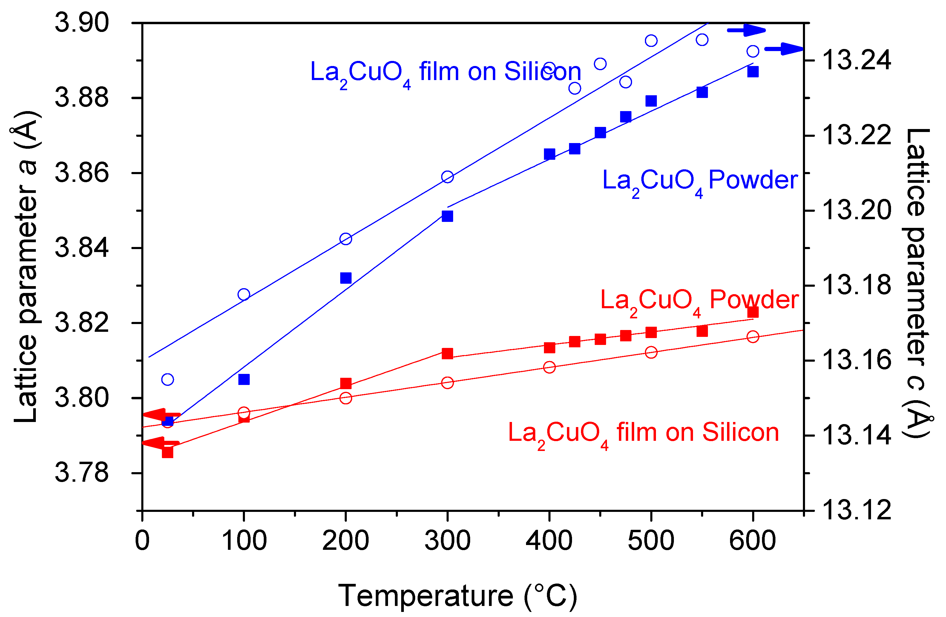
In addition to the crystallization of lanthanum cuprate film using ex situ method, the evolution of the X-ray diffractogram during in situ air annealing has been also monitored. These experiments confirm the results presented in Figure 1 and Figure 2. They also bring relevant new information. Indeed, the tetragonal lattice constants have been estimated after film crystallization during its cooling to room temperature. The Figure 3 shows the evolution of the La2CuO4 lattice parameters as a function of the temperature for a lanthanum cuprate film and for a commercial powder. The lattice parameter values are the mean value of the parameters calculated by fitting five times the diffractograms obtained by this in situ method with Celref software. The thermal evolution of the lattice constants can be used to estimate the apparent thermal expansion coefficient (α) using
α = a a 0 × 1 T
The slope of the straight line in the Figure 3 is equal to α × a 0 where a0 corresponds to the lattice constant measured at room temperature. ∆a corresponds to the variation of the lattice constant in the temperature range ∆T. In order to check the accuracy of this method, a (100) silicon substrate was cooled from 600 °C to the room temperature. From the evolution of its lattice constant, the thermal expansion coefficient was estimated to 3.2 × 10⁻⁶ K−1 (Table 2). Since this value is very close to that of bulk silicon (2.9 × 10⁻⁶ K−1) the procedure used to estimate α can be validated. The same analyses were performed on commercial La2CuO4 powder. When this oxide is stoichiometric a structural change occurs at 250 °C [8]. At low temperatures, the structure is orthorhombic (Bmab) and a tetragonal form (I4/mmm) is encountered at high temperatures. For the commercial powder, the evolution of the lattice constant as a function of the temperature clearly evidences a change of the slope at approx. 300 °C that is due to the structural change of lanthanum cuprate. From these lines, the thermal expansion coefficient (TEC) of the two structures of La2CuO4 have been estimated (Table 2) [23,24]. Since few values of La2CuO4 TEC are detailed in the literature, the comparison of the values is difficult [25]. However, the TEC value obtained for the orthorhombic phase (15 × 10−6 K−1 in the a direction) is in agreement with that previously published [23]. Since the tetragonal phase exhibits a TEC value (10.2 × 10⁻⁶ K−1) lower than that of the orthorhombic phase, the measurement of the thermal expansion coefficient of lanthanum cuprate should allow to distinguish between the two above-mentioned structures. The sputtered lanthanum cuprate thin film exhibits a TEC of 10.5 × 10⁻⁶ K−1 in the a direction (Table 2). This result confirms the assignment of the X-ray diffraction analyses. Even at room temperature the films crystallizes in a metastable tetragonal form. Such behavior may be explained considering either a possible non-stoichiometry or internal stresses.

3.2. Effect of Thermal Stress on Film Surface Morphology

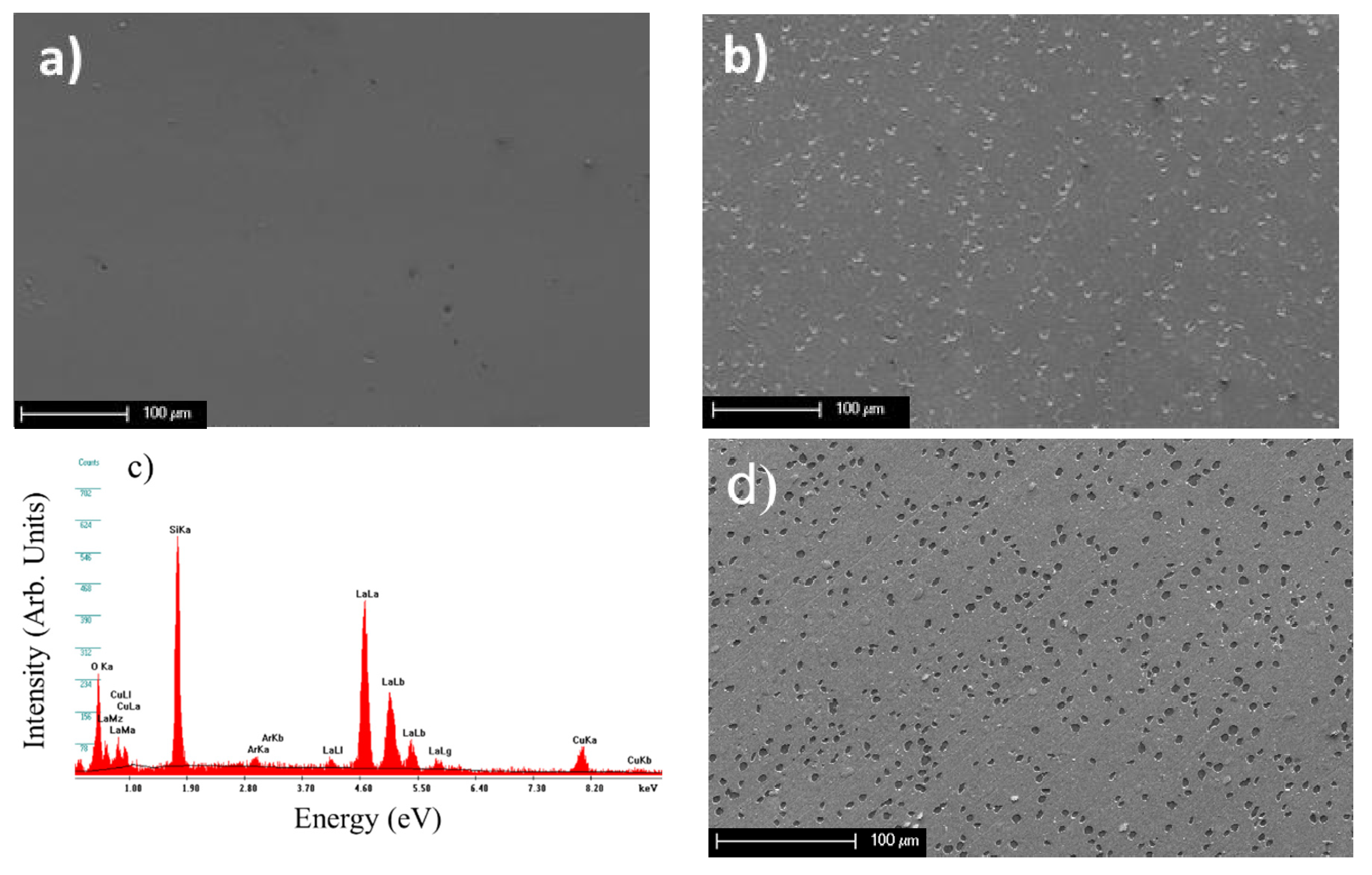
SEM observations to examine the change in the surface morphology were performed before and after the annealing at 600 °C during two hours. Before the thermal treatment, apart from growth defects, a smooth surface is evidenced (Figure 4a). This morphology is due to the amorphous state of the sample. After annealing, a partial delamination of the film occurs with circular hole shape (Figure 4b). Figure 4c presents a typical EDS spectrum obtained on the surface of an adherent area of the annealed film. The EDS analyses performed in holes did not show any trace of lanthanum or copper, indicating that the delamination occurs at the film-substrate interface. Three hypotheses may explain this delamination. The first one involves a reaction between air and the film, that would have changed the chemical composition of the coating. However, with the films being already fully oxidized, such a hypothesis cannot be further considered. The second hypothesis is related to the degassing of the substrate. Finally, the third hypothesis corresponds to the stresses that induce delamination of the thin films. To verify these hypotheses, the films were annealed under vacuum (approx. 10−4 Pa) (Figure 4d). The delamination observed after the vacuum annealing allows us to put aside this assumption. Furthermore, since silicon does not degas during air annealing, the second hypothesis cannot be further considered. Consequently, the formation of the flakes is more likely due to the result of stress generated at the film–substrate interface. The peculiar shape of the flakes is typical of homogeneous compressive stress [26,27]. It is well known that the deposition parameter can modify the internal stress in the films [27], especially the total pressure during the deposition [28].
The increase of the total pressure in the deposition chamber decreases the number of holes, the shape of the flakes is less circular and their diameter seems higher. An image processing software (WSxM) has been used to estimate the surface fraction after annealing that is not covered by the lanthanum cuprate thin film anymore [29]. A decrease of this fraction from 32% for a film deposited at 1 Pa to 22% for a film deposited at 4 Pa has been estimated. Such behavior can be explained considering that the increase of deposition pressure comes with a decrease of the compressive stress into the deposited films.
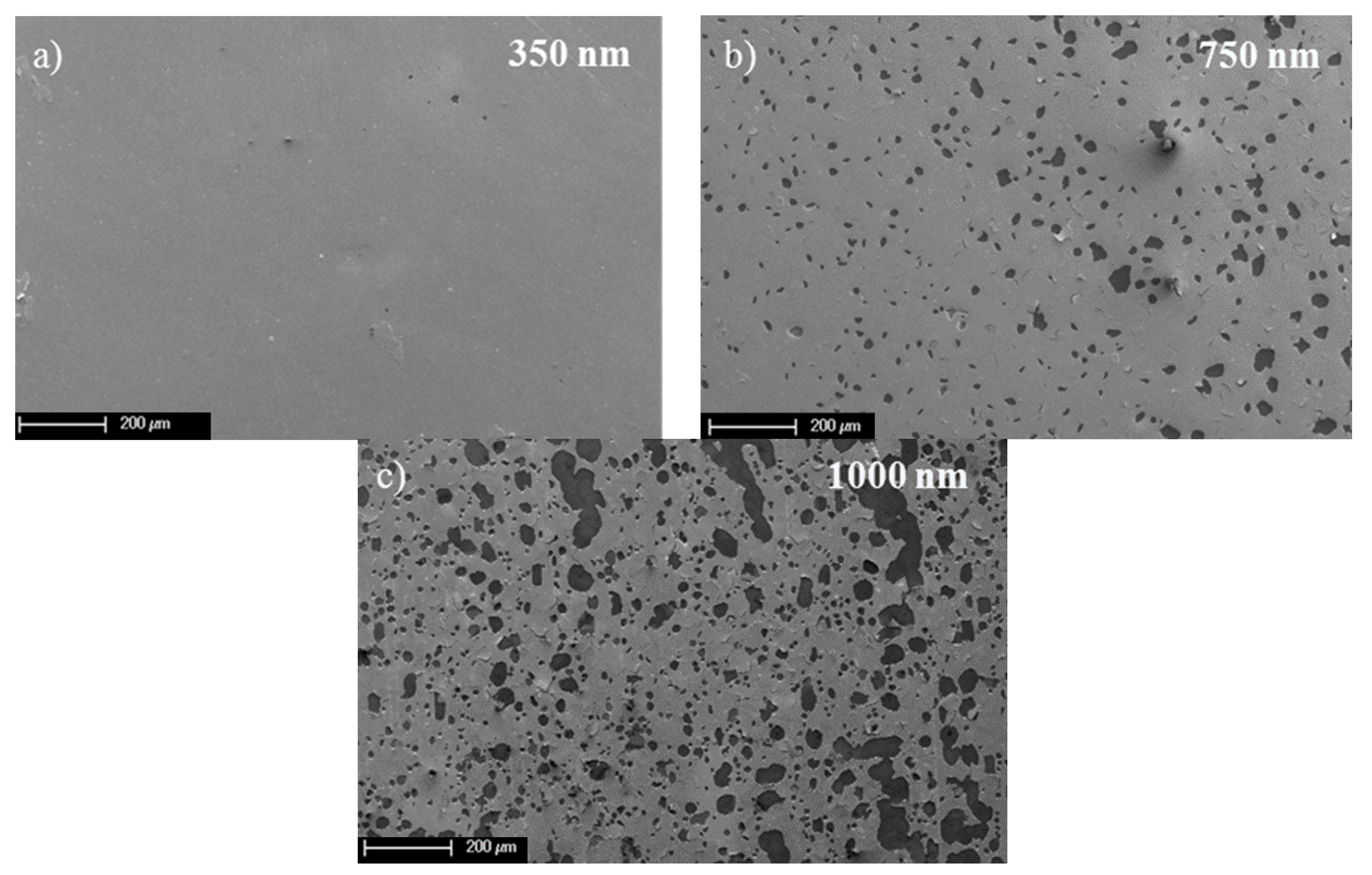
Another way to modify the mechanical behavior of the film is to vary its thickness. Indeed, the thinner films possess a greater capacity of adaptation to stress than the thicker ones. As shown in Figure 5 for a thickness of 350 nm, only a few holes are evidenced after air annealing. The delaminated surface percentage was estimated of 0.02%. When the thickness increases to 750 nm and 1000 nm, the uncovered surface after annealing increases up to 8% and 27%, respectively. Thus, within our deposition conditions, the critical thickness beyond which delamination occurs is ranging between 350 and 750 nm [30]. Conversely to the effect of the deposition pressure, the increase of the film thickness induces in an increase of the hole density. Then, to reduce the formation of holes after annealing, the lanthanum cuprate films should exhibit a low thickness and be deposited at high total pressure.
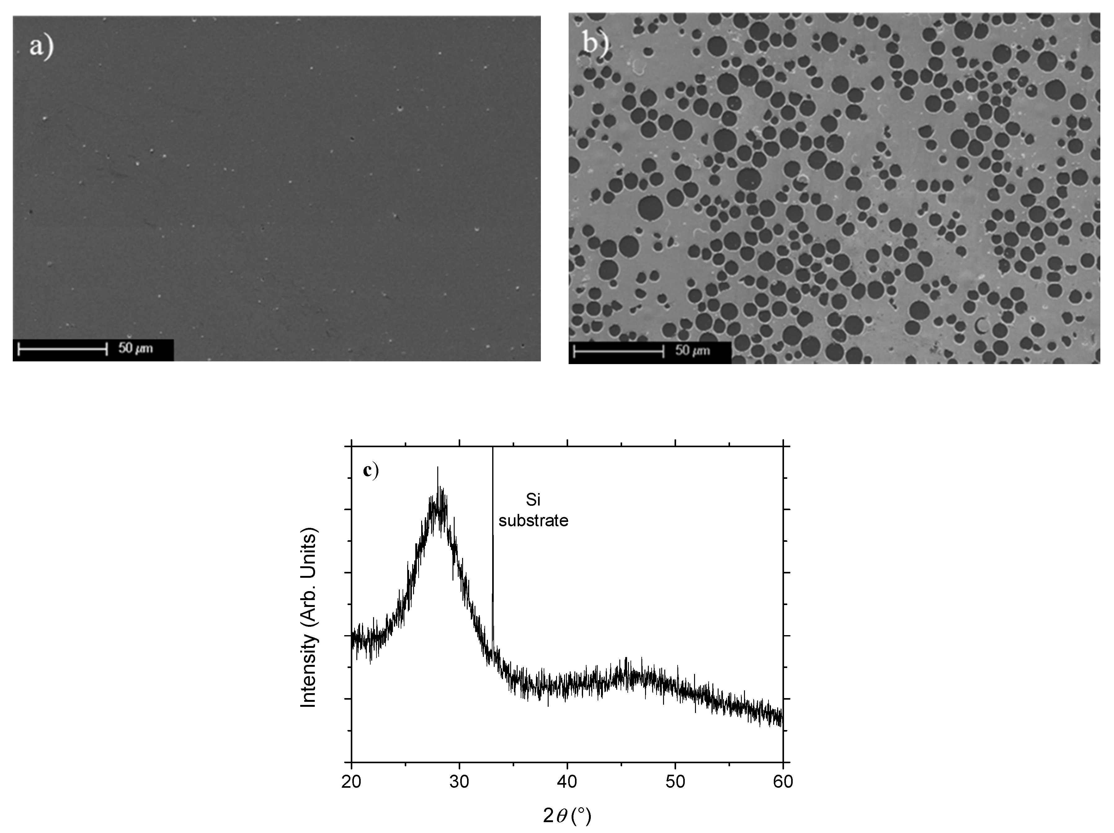
Holes observed on the previous figures may result from compressive stresses. Usually, amorphous films present a density lower than that of crystalline ones. The crystallization of the lanthanum cuprate films should not induce compressive stress that is responsible for hole formation. In order to determine when the delamination of the films occurs, air annealing treatments of two hours have been performed at various temperatures from 100 to 600 °C with a step of 25 °C. After each annealing, the surface morphology of the films was checked by SEM and their structure was determined by XRD. For temperatures lower than or equal to 250 °C, no delamination has been evidenced by SEM (Figure 6a). On the other hand, holes are clearly observed when the temperature reaches 275 °C (Figure 6b). Since the XRD analysis confirms that the films are still X-ray amorphous (Figure 6c), the observed delamination implies that the volume change induced by the crystallization is not the cause of the flakes formation. The buckling of the film, caused by important compressive stress [31,32], is observed. To show if the flakes formation occurs during the heating or the cooling step of the samples, in situ observation of the annealing has been performed by ESEM.
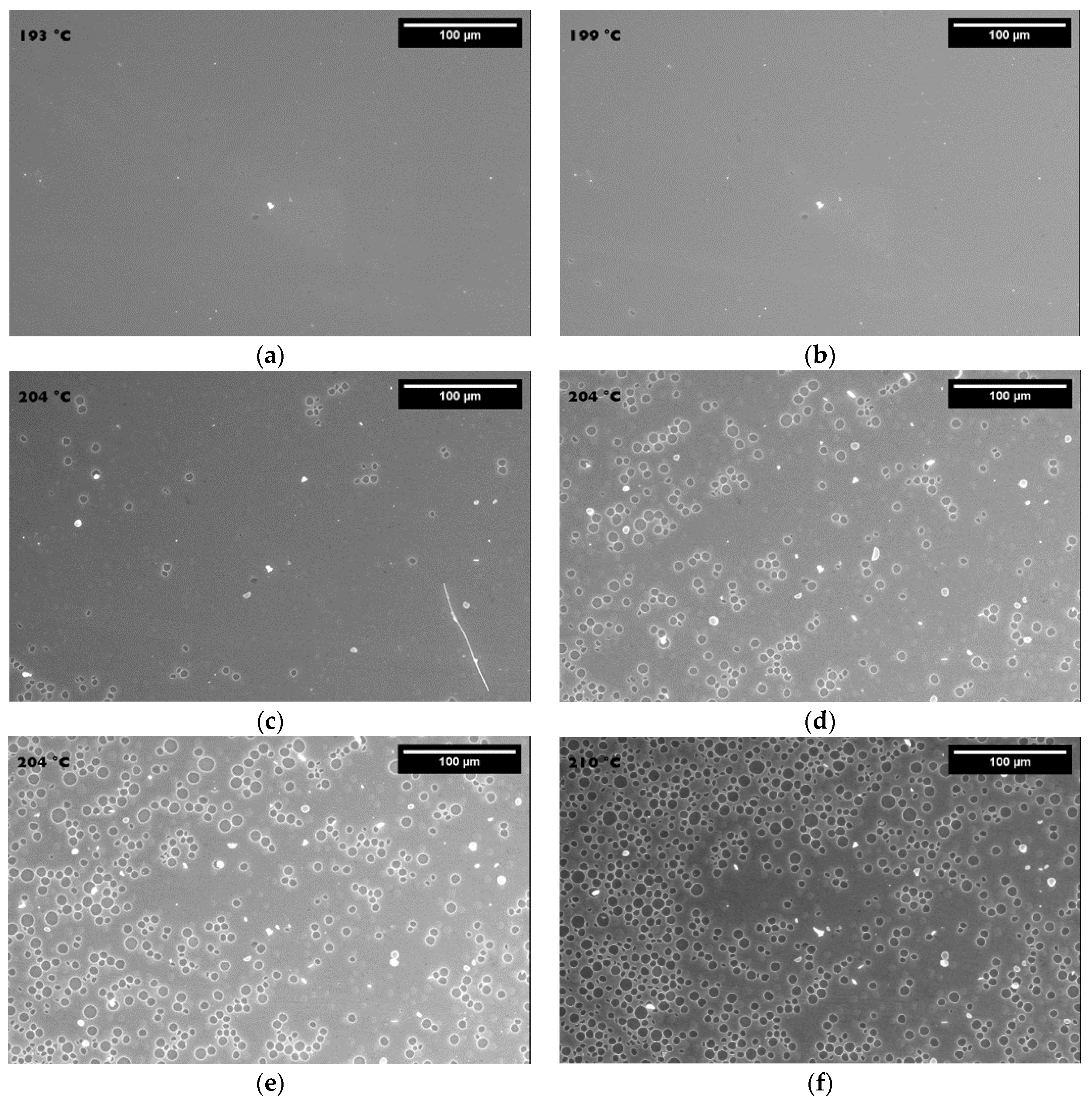
Figure 7 shows the ESEM observations made at different temperatures. However, the values of the temperature measured in the ESEM equipment cannot be strictly compared to those previously measured using others furnaces [33]. Furthermore, the annealing atmosphere is different: air for in situ XRD annealing or during ex situ annealing and water vapor for ESEM. Nevertheless, ESEM experiments can bring qualitative relevant information regarding mechanistic aspects [34]. It may clearly identify when the delamination occurs [35,36,37]. Before the temperature of 199 °C, no change is noticed at the film surface. At the temperature of 199 °C, the first hole appears. When the temperature reaches 204 °C, the number of holes has already increased. The delamination of the film increases quickly. In addition, the formation of blister is observed at the surface. Therefore, the formation of the flakes begins by the buckling of the film then by the failure of the film when the stress reaches a critical value. It can be noticed that the hole diameters are homogeneous at the beginning of the phenomena. The scatter diameter increases with the temperature due to the combined effect of the increasing stress with the temperature and the local relaxation by the already existing holes. The buckling and delamination phenomena stabilize at the temperature of 210 °C. No significant changes appear after the heating until 700 °C and during the cooling of the sample. Thus, the buckling and the failure of the films appears during the heating part of the annealing.
The thermal expansion coefficient of the film is higher than that of the silicon substrate (Table 2). Thus, the film expands more than the substrate during a heating step. However, its adhesion to the substrate prevents the film from freely expand, generating compressive stress in the material. When the stress is higher than a critical value, the film is lifted off the substrate at an interfacial surface flaw [38] and produces a blister. The particular circular shape of the blister is due to the equi-biaxal stress in the plane, causing a homogeneous lifting of the film. This phenomenon decreases the stress level in the film. However, when the temperature still increases, the stress raises again. When the stress reaches another threshold, the blister cracks at the point where the compressive stress are the greater, at the debonded film/adherent film [29] interface and at the film/air interface. It propagates in depth and at the perimeter of the blister. When the crack reaches the film-substrate interface the blister pops out leaving only a hole. This affirmation is supported by SEM observation of a double diameter side of a hole. This double diameter side is caused by a plastic damage of the film [29] and the failure of the blister.

4. Conclusions

Amorphous lanthanum cuprate films were deposited by reactive magnetron sputtering on silicon substrates. Air annealing was performed to ensure the crystallization of the films. It occurred at a temperature of 460 °C and showed the improvement of the film crystallinity until the temperature reached 510 °C. The in situ XRD analyses during annealing have been used to determine the thermal expansion coefficient of the films. The obtained results showed that the apparent thermal expansion coefficients of the films are similar to those of the tetragonal La2CuO4 structure. This value allowed us to explain the delamination of the film that occurred during the heating step as confirmed by ESEM analyses. The difference in thermal expansion coefficient of the substrate and the film generate compressive stress causing blisters and finally holes. The diameter and density of holes can be tuned by modifying the internal stress of the films. We have also shown that by changing the deposition pressure and decreasing the thickness of the film, the holes formation can be avoided.
Since the formation of a crystalline La2CuO4 thin film requires an annealing step at temperature higher than 500 °C, the present study clearly shows that the choice of the substrate nature is crucial to use La2CuO4 thin film for some technological applications. The thermal expansion coefficient mismatch between the substrate and the film being the reason for the film delamination, it is necessary to deposit the films on a substrate having a thermal expansion coefficient close to that of La2CuO4 (approx. 10 × 10−6 K−1).

Author Contributions

Investigation, N.T., P.S., A.M., P.B., and F.C.; writing—original draft preparation, N.T.; writing—review and editing, J.-F.P.; supervision, J.-P.B. and J.-F.P.; funding acquisition, J.-F.P. All authors have read and agreed to the published version of the manuscript.

Funding

This research was funded by the Région Lorraine and the Institut Carnot Energie Environnement Lorraine (ICEEL).

Acknowledgments

The authors thank the METSA network and the Clym Platform for supporting the E-SEM investigations.

Conflicts of Interest

The authors declare no conflict of interest.

References

  1. Si, W.; Xi, X.X. Epitaxial-strain-induced insulator-superconductor transition in undoped and lightly doped La2CuO4. Appl. Phys. Lett. 2001, 78, 240. [Google Scholar] [CrossRef]
  2. Hundley, M.F.; Kwok, R.S.; Cheong, S.W.; Thompson, J.D.; Fisk, Z. Anisotropic electronic and thermal transport properties of lightly oxygen-doped La2CuO4+δ. Phys. C Supercond. 1991, 172, 455–464. [Google Scholar] [CrossRef] [Green Version]
  3. Briois, P.; Oliveira, J.C.; Lapostolle, F.; Perry, F.; Billard, A.; Cavaleiro, A. Synthesis and electrical properties of Ln2CuO4+δ (Ln: Nd or La) mixed conductor sputter deposited coatings. Ionics 2008, 14, 455–461. [Google Scholar] [CrossRef] [Green Version]
  4. Rial, C.; Morán, E.; Alario-Franco, M.A.; Amador, U.; Andersen, N.H. Room temperature chemically oxidized La2CuO4+y: Phase separation induced by thermal treatment. Phys. C Supercond. Appl. 1997, 278, 122–134. [Google Scholar] [CrossRef]
  5. Dong, X.L.; Dong, Z.F.; Zhao, B.R.; Zhao, Z.X.; Duan, X.F.; Peng, L.M.; Huang, W.W.; Xu, B.; Zhang, Y.Z.; Guo, S.Q. Direct Observation of Incommensurate Modulation in Phase-Separated Cu-Rich La2CuO4.003. Phys. Rev. Lett. 1998, 80, 2701–2704. [Google Scholar] [CrossRef]
  6. Locquet, J.; Arrouy, F.; Mächler, E.; Despont, M.; Bauer, P.; Williams, E.J. Local electrochemical oxidation/reduction: First step towards a new lithography? Appl. Phys. Lett. 1996, 68, 1999–2001. [Google Scholar] [CrossRef]
  7. Radaelli, P.G.; Hinks, D.G.; Mitchell, A.W.; Hunter, B.A.; Wagner, J.L.; Dabrowski, B.; Vandervoort, K.G.; Viswanathan, H.K.; Jorgensen, J.D. Structural and superconducting properties of La2-xSrxCuO4 as a function of Sr content. Phys. Rev. B 1994, 49, 4163–4175. [Google Scholar] [CrossRef]
  8. Grenier, J.C.; Lagueyte, N.; Wattiaux, A.; Doumerc, J.P.; Dordor, P.; Etourneau, J.; Pouchard, M.; Goodenough, J.B.; Zhou, J.S. Transport and magnetic properties of the superconducting La2CuO4+δ phases (0 <δ <0.09) prepared by electrochemical oxidation. Phys. C Supercond. Its Appl. 1992, 202, 209–218. [Google Scholar]
  9. Sinnarasa, I.; Thimont, Y.; Presmanes, L.; Barnabé, A.; Tailhades, P. Thermoelectric and Transport Properties of Delafossite CuCrO2:Mg Thin Films Prepared by RF Magnetron Sputtering. Nanomaterials 2017, 7, 157. [Google Scholar] [CrossRef] [Green Version]
  10. García-Wong, A.C.; Pilloud, D.; Bruyère, S.; Mathieu, S.; Migot, S.; Pierson, J.F.; Capon, F. Oxidation of sputter-deposited vanadium nitride as a new precursor to achieve thermochromic VO2 thin films. Sol. Energy Mater. Sol. Cells 2020, 201, 110474. [Google Scholar] [CrossRef]
  11. Pilloud, D.; Pierson, J.F.; Takadoum, J. Structure and tribological properties of reactively sputtered. Zr–Si–N films Thin Solid Films 2006, 496, 445–449. [Google Scholar] [CrossRef]
  12. Petitjean, C.; Grafouté, M.; Pierson, J.F.; Rousselot, C.; Banakh, O. Structural, optical and electrical properties of reactively sputtered iron oxynitride film. J. Phys. D Appl. Phys. 2006, 39, 1894–1898. [Google Scholar] [CrossRef]
  13. Capon, F.; Horwat, D.; Pierson, J.F.; Zaghrioui, M.; Laffez, P. Thermochromic effect in NdNiO3-δ thin films annealed in ambient air. J. Phys. D Appl. Phys. 2009, 42, 182006. [Google Scholar] [CrossRef]
  14. Orikasa, Y.; Hayashi, N.; Muranaka, S. Effects of oxygen gas pressure on structural, electrical, and thermoelectric properties of (ZnO)3In2O3 thin films deposited by rf magnetron sputtering. J. Appl. Phys. 2008, 103, 113703. [Google Scholar] [CrossRef]
  15. Stranak, V.; Wulff, H.; Rebl, H.; Zietz, C.; Arndt, K.; Bogdanowicz, R.; Nebe, B.; Bader, R.; Podbielski, A.; Hubick, Z.; et al. Deposition of thin titanium–copper films with antimicrobial effect by advanced magnetron sputtering methods. Mater. Sci. Eng. C 2011, 31, 1512–1519. [Google Scholar] [CrossRef]
  16. Saadat, M.; George, A.E.; Hewitt, K.C. Densely mapping the phase diagram of cuprate superconductors using a spatial composition spread approach. Phys. C Supercond. 2010, 470, S59–S61. [Google Scholar] [CrossRef]
  17. Liu, Y.; Wan, S.L.; Li, X.G. Excess oxygen doping in chemically oxidized La2CuO4+δ films studied by x-ray diffraction and Raman scattering. Supercond. Sci. Technol. 2007, 20, 870–874. [Google Scholar]
  18. Tranvouez, N.; Pierson, J.F.; Capon, F.; Bauer, P. Effect of the deposition process on the composition and structure of sputtered lanthanum cuprate films. Surf. Coat. Technol. 2011, 205, S254–S257. [Google Scholar] [CrossRef]
  19. Zhu, X.; Defaÿ, E.; Guigues, B.; Le Rhun, G.; Dubarry, C.; Aïd, M. Low-temperature fabrication of Ba1-xSrxTiO3 thin films with good dielectric properties on platinized sililcon substrates. J. Eur. Ceram. Soc. 2010, 30, 471–474. [Google Scholar] [CrossRef]
  20. Zhu, Y.; Wang, H.; Liu, P.; Yao, W.; Cao, L. Preparation and conducting performance of LaNiO3 thin film on Si substrate. Thin Solid Films 2005, 471, 48–52. [Google Scholar] [CrossRef]
  21. Chen, C.; Smith, D.C.; Gay, P.; Ryan, J.F. Flux growth of superconducting La2CuO4 single crystals. Phys. C Supercond. 2000, 341, 535–536. [Google Scholar] [CrossRef]
  22. Boileau, A.; Capon, F.; Coustel, R.; Laffez, P.; Barrat, S.; Pierson, J.F. Inductive effect of Nd for Ni3+ stabilization in NdNiO3 synthesized by reactive DC co-sputtering. J. Phys. Chem C 2017, 121, 21579–21590. [Google Scholar] [CrossRef]
  23. Boehm, E.; Bassata, J.M.; Steil, M.C.; Dordor, P.; Mauvy, F.; Grenier, J. C Oxygen transport properties of La2Ni1−xCuxO4+δ mixed conducting oxides. Solid State Sci. 2003, 5, 973–981. [Google Scholar] [CrossRef]
  24. Watanabe, H.; Yamada, N.; Okaji, M. Linear Thermal Expansion Coefficient of Silicon from 293 to 1000 K. Inter. J. Thermophys. 2004, 25, 221–236. [Google Scholar] [CrossRef]
  25. Lang, M.; Kürsch, R.; Grauel, A.; Geibel, C.; Steglich, F.; Rietschel, H.; Wolf, T.; Hidaka, Y.; Kumagai, K.; Maeno, Y. Lattice Instabilities in Cuprate Superconductors: A Possible Limiting Mechanism for Tc. Phys. Rev. Lett. 1992, 69, 482–485. [Google Scholar] [CrossRef] [PubMed]
  26. Audoly, B. Mode-dependent toughness and the delamination of compressed thin films. J. Mech. Phys. Solids 2000, 48, 2315–2332. [Google Scholar] [CrossRef]
  27. Teixeira, V. Mechanical integrity in PVD coatings due to the presence of residual stresses. Thin Solid Films 2001, 392, 276–281. [Google Scholar] [CrossRef]
  28. Sasabayashi, T.; Ito, N.; Nishimura, E.; Kon, M.; Song, P.K.; Utsumi, K.; Kaijo, A.; Shigesato, Y. Comparative study on structure and internal stress in tin-doped indium oxide and indium-zinc oxide films deposited by rf magnetron sputtering. Thin Solid Films 2003, 445, 219–223. [Google Scholar] [CrossRef]
  29. Coupeau, C.; Goudeau, P.; Belliard, L.; George, M.; Tamura, N.; Cleymand, F.; Colin, J.; Perrin, B.; Grilhé, J. Evidence of plastic damage in thin films around buckling structures. Thin Solid Films 2004, 469–470, 221–226. [Google Scholar] [CrossRef]
  30. Eymery, J.P.; Denanot, M.F. Blisters in as-deposited films of bcc stainless steel. Surf. Coat. Technol. 1996, 80, 251–254. [Google Scholar] [CrossRef]
  31. Hyun, D.C.; Moon, G.D.; Park, C.J.; Kim, B.S.; Xia, Y.; Jeong, U. Buckling-Assisted Patterning of Multiple Polymers. Adv. Mater. 2010, 22, 2642–2646. [Google Scholar] [CrossRef] [PubMed]
  32. Romana, L.; Fuchs, G.; Massouras, G.; Thevenard, P. Blister formation in alumina thin films bombarded with xenon ions Radiat. Eff. Defects Solids 1990, 115, 139–143. [Google Scholar] [CrossRef]
  33. Podor, R.; Pailhon, D.; Ravaux, J.; Brau, H.P. Development of an Integrated Thermocouple for the Accurate Sample Temperature Measurement during High Temperature Environmental Scanning Electron Microscopy (HT-ESEM) Experiments. J. Microscopy 2015, 21, 307–312. [Google Scholar] [CrossRef]
  34. Etiemble, A.; Der Loughian, C.; Apreutesei, M.; Langlois, C.; Cardinal, S.; Pelletier, J.M.; Pierson, J.F.; Steyer, P. Innovative Zr-Cu-Ag thin film metallic glass deposed by magnetron PVD sputtering for antibacterial applications. J. Alloys Compd. 2017, 707, 155–161. [Google Scholar] [CrossRef]
  35. Mège-Revil, A.; Steyer, P.; Cardinal, S.; Thollet, G.; Esnouf, C.; Jacquot, P.; Stauder, B. Correlation between thermal fatigue and thermomechanical properties during the oxidation of multilayered TiSiN nanocomposite coatings synthesized by a hybrid physical/chemical vapour deposition process. Thin Solid Films 2010, 518, 5932–5937. [Google Scholar] [CrossRef]
  36. Mège-Revil, A.; Steyer, P.; Thollet, G.; Chiriac, R.; Sigala, C.; Sanchéz-Lopéz, J.C.; Esnouf, C. Thermogravimetric and in situ SEM characterisation of the oxidation phenomena of protective nanocomposite nitride films deposited on steel. Surf. Coat. Technol. 2009, 204, 893–901. [Google Scholar] [CrossRef]
  37. Jacquet, P.; Song, B.; Podor, R.; Lautru, J.; Trejo, E.; Cooper, S.J.; Teisseire, J.; Gozhyk, I.; Jupille, J.; Lazzari, R. Direct Observation of Metallic Thin Layers Dewetting by HT-ESEM. Microsc. Microanal. 2019, 25, 69–70. [Google Scholar] [CrossRef] [Green Version]
  38. Yu, H.H.; He, M.Y.; Hutchinson, J.W. Edge effects in thin film delamination. Acta Mater. 2001, 49, 93–107. [Google Scholar] [CrossRef]
Figure 1. Effect of a 2 h air annealing treatment on the X-ray diffractograms of a La–Cu–O film with an atomic ratio La/Cu of 2.14 deposited on a silicon substrate with a SrTiO3 sublayer (analysis condition: Co Kα radiation).
Coatings 10 00613 g001
Figure 2. Evolution of the diffraction peak intensity as a function of the annealing temperature for the (101), (110), (103), (004) peaks on the tetragonal form of La2CuO4.
Coatings 10 00613 g002
Figure 3. Evolution of the lattice constant of a thin film and a commercial powder of La2CuO4 as a function of the temperature. The straight lines correspond to a fit of the experimental data. For the La2CuO4 powder, the change of the slope at approx. 300 °C is due to the structural change (transformation of orthorhombic phase to a tetragonal one when the temperature increases).
Coatings 10 00613 g003
Figure 4. Surface morphology of a La2CuO4 thin film (a) as-deposited, (b) after an air annealing during two hours at a temperature of 600 °C, (c) EDS spectrum obtained on the adherent film from Figure 4b, and (d) after a vacuum annealing (2 h at 600 °C).
Coatings 10 00613 g004
Figure 5. SEM observation after annealing at a temperature of 600 °C of a La2CuO4 film with a thickness of (a) 350 nm, (b) 750 nm, and (c) 1000 nm.
Coatings 10 00613 g005
Figure 6. Surface morphology of (a) an as-deposited film, (b) after an air annealing at a temperature of 275 °C for 2 h, and (c) X-ray diffractogram of the film annealed at 275 °C.
Coatings 10 00613 g006
Figure 7. Evolution of the film surface morphology by ESEM for various temperatures. (a) 193 °C; (b) 199 °C; (c–e) 204 °C; (f) 210 °C.
Coatings 10 00613 g007
Table 1. Experimental conditions for the elaboration of the La-Cu-O films
ParametersValues
Target diameter and thickness (mm)50 and 3
Distance between target and substrates (cm)7
Argon flow rate (sccm)20
Oxygen flow rate (sccm)10
Total pressure (Pa)0.6–4.6
Temperature (°C)Approx. 50
Table 2. Thermal expansion coefficient of silicon, commercial powder, and thin film calculated in this work and reference values
Sample NatureApparent TEC Measured Value for the Lattice Parameter a (106 K−1)Apparent TEC Measured Value for the Lattice Parameter c (106 K−1)Literature Value
Film on silicon10.5 ± 0.111.0 ± 0.5-
La2CuO4 powder in orthorhombic form15 ± 113.0 ± 0.513 [23]
La2CuO4 powder in tetragonal form10.2 ± 0.210 ± 2-
Silicon3.2 ± 0.2-2.9 [24]