Abstract
Double glow plasma surface metallurgy (DGPSM) technology was applied to obtain a Fe-Al-Cr coating on the surface of Q235 carbon steel. The influence of the sample temperature, gas pressure, the distance between the substrate, and the source electrode on the quality of the obtained Fe-Al-Cr coatings was systematically investigated. The results showed that the parameters for DGPSM have a significant effect on the uniformity, particle size, compactness, and thickness of the coating. Under the optimized parameters (sample temperature: 800 °C, gas pressure: 35 Pa, and electrode distance: 15 mm), the obtained Fe-Al-Cr coating contains Fe2AlCr, Fe3Al(Cr), FeAl(Cr), Fe(Cr) solid solution, Cr23C6, and α-Fe(Al), exhibiting excellent corrosion resistance in a 0.5 mol/L H2SO4 solution, which is even better than that of the 304 stainless steel.
1. Introduction
Carbon steel can be widely used in the industrial manufacturing area, such as in boiler pipe, chemical reactor, and pressure vessel in the petroleum chemical industry, or the cabin of the ship in the marine vehicle industry [1,2,3]. Owing to the harsh service environment, surface technology should be used to prepare coatings with excellent corrosion resistance, wear resistance, and oxidation resistance [4,5,6]. Depositing a high-quality Fe-Al-Cr coating on the surface of carbon steel is highly desirable.
Strategies such as hot dipping, resurfacing welding, and thermal spraying have been developed to fabricate Fe-Al-Cr coatings. However, the coatings obtained by hot dipping create a rough surface, and in most cases, the coating can be used only after tedious annealing treatment [7]. The disadvantage of the resurfacing welding technology is the existence of excessive thermal stress due to the unsatisfactory process, which would cause cracks on the obtained coating. For thermal spraying technology, the arc burning and evaporation of the alloying elements not only would decrease the content of the chemical composition in the coating, but also would form porosity and cracks [8]. Hence, proper surface technology is highly desirable for the fabrication of a Fe-Al-Cr coating on carbon steels.
The operating principle of double glow plasma surface metallurgy (DGPSM) technology is schematically illustrated in Figure 1a, where the anode, the cathode, and the source electrode are placed in a container filled with inert gas (Ar). Fe-Al-Cr wires forming a mesh structure are used as the source electrode (Figure 1b). When high voltages are applied between the anode and the cathode, and the anode and the source electrode, the Ar gas is ionized and becomes plasma. Then, the glow discharge phenomenon appears, which transfers the alloying elements from the source electrode to the substrate at the cathode, and it can also activate the surface of the substrate to promote the diffusion of the deposited elements to form a diffusion layer. DGPSM has been regarded as an advanced surface technology for the deposition of high-quality coatings. For example, Al2O3-particles-reinforced Fe-Al coatings were prepared on the surface of 316 L stainless steel by a DGPSM technology and exhibited enhanced wear resistance and corrosion resistance [9]. Similarly, Nb was incorporated into Fe-Al coatings to form Fe-Al-Nb coatings by a DGPSM process, which showed improved mechanical properties [10].

Figure 1.
The schematic diagram of double glow plasma surface metallurgy (DGPSM) technology (a) and the mesh structure of the source electrode (b).
During the processing of DGPSM, the chemical composition and the thickness of the coating are closely related to the plasma temperature, the gas pressure, and the electrode distance (i.e., distance between the substrate and the source electrode) [11]. A deep understanding of the effects of these parameters on the quality of the obtained Fe-Al-Cr coating is very important to control the mechanical and chemical properties of the coating. However, this kind of study is still lacking. Herein, we focused on the influence of the sample temperature, gas pressure, and electrode distance on the microstructure, morphology, and quality of the obtained Fe-Al-Cr coating deposited on Q235 steel substrates. It was found that Fe-Al-Cr coatings obtained under optimized conditions exhibit excellent corrosion resistance in a 0.5 mol/L H2SO4 solution, which is even better than that of the 304 stainless steel. The new findings demonstrated in this work provide useful information for the fabrication of high-quality Fe-Al-Cr coatings with excellent corrosion resistance.
2. Experiments
2.1. Source Electrode
Fe-Al-Cr wires forming a mesh structure were used as the source electrode (φ100 × 1.5 mm2), as schematically illustrated in Figure 1b. The chemical composition of the source electrode was Al: 5 wt.% and Cr: 25 wt.%, and the balance: Fe with a mesh aperture of approximately 2 mm.
2.2. Cathode
Q235 low-carbon steel substrate was used as the cathode, which consisted of C: 0.16 wt.%, M: 0.40 wt.%, Si: 0.30 wt.%, S: 0.050 wt.%, P: 0.045 wt.%, and the balance: Fe. The total dimensions of a Q235 plate were 60 mm × 60 mm × 3 mm. The substrate samples were cut into small plates with dimensions of 15 mm × 15 mm × 3 mm, followed by being polished with 20 mesh brown corundum and ultrasonically cleaned in acetone before DGPSM.
2.3. The Equipment and Procedures
As shown in Figure 1a, the double glow plasma surface metallurgy device was composed of three parts, namely the vacuum system, the power system, and the furnace. Fe-Al-Cr target with a mesh structure was laid on the source electrode, in the center of the equipment, and a Q235 carbon steel substrate was placed on the cathode, at the bottom of the equipment. The temperature of the sample was monitored by the optical pyrometer (WGG2-201, Shanghai Automation Instrumentation Co., Ltd., Shanghai, China), and the gas pressure was regulated by controlling the degree of vacuum and the input of argon.
2.4. Morphology and Structure Characterization
Surface morphologies and chemical composition distributions of the Fe-Al-Cr coatings were performed by a QUANTA 200 scanning electron microscope (SEM, Hillsboro, OR, USA) equipped with an energy-dispersive spectroscope (EDS). The cross-sectional microstructure and the thickness of the alloyed layers were measured by a MM-6 metallographic microscope (MM, Shanghai Wanheng Precision Instruments Co., Ltd., Shanghai, China). The phase composition of Fe-Al-Cr coatings was identified by Bruker D8-ADVANCE X-ray diffraction (XRD, Bruker, Billerica, MA, USA), with Cu Kα as the radiation source, with a scanning speed of 5°/min, and the radiation conditions of 40 kV and 40 mA. An HXS-1000A micro-hardness tester (Shanghai Milite Precise Instrument Co., Ltd., Shanghai, China) was used to test the micro-hardness at the load of 100 g and maintained for 15 s.
2.5. Electrochemical Test
Electrochemical tests were applied to investigate the corrosion resistance of Fe-Al-Cr coatings, 304 stainless steel (chemical composition: Cr: 18.529 wt.%, Ni: 8.545 wt.%, Mn: 1.309 wt.%, Si: 0.331 wt.%, Cu: 0.303 wt.%, C: 0.063 wt.%, P: 0.036 wt.%, S: 0.025 wt.%, and Fe: the balance), and Q235 low carbon steel. Firstly, the samples were embedded in epoxy resin, to prepare the working electrodes, and a Pt foil was used as the counter electrode, and a saturated calomel electrode was used as the reference electrode. To remove the grease and avoid any damage on the Fe-Al-Cr coatings, the prepared Fe-Al-Cr coating electrodes were only ultrasonically cleaned in acetone for 15 min, without polishing. For the 304 stainless steel and Q235 low-carbon steel electrodes, the samples were polished with 20 mesh brown corundum and ultrasonically cleaned in acetone for 15 min. In the presence of a 0.5 mol/L H2SO4 solution, anodic polarization and electrochemical impedance spectroscopy (EIS) tests were performed. To ensure the accuracy, two repeated experiments were carried out for each sample.
3. Results and Discussion
3.1. The Effect of the Sample Temperature on Microstructure of the Fe-Al-Cr Coating
To study the effect of the sample temperature on the obtained Fe-Al-Cr alloyed layer, the sample temperature was varied in the range of 750–900 °C, while other parameters were set as follows: the voltage of source electrode (Vs = 850–950 V), the voltage of cathode (Vc = 450–550 V), the depositing time (t = 3.5 h), the gas pressure (P = 35 Pa), and the electrode distance (d = 15 mm). Surface and cross-sectional morphologies of the Fe-Al-Cr alloyed layers obtained at different sample temperatures (750, 800, 850, and 900 °C) are shown in Figure 2.
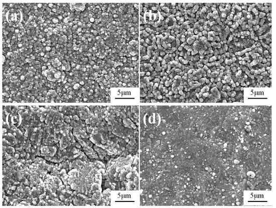
Figure 2.
Surface morphologies of the Fe-Al-Cr alloyed layers obtained at different sample temperatures: (a) 750 °C; (b) 800 °C; (c) 850 °C; (d) 900 °C.
As shown in Figure 2a, when the sample temperature is 750 °C, the obtained Fe-Al-Cr coating is composed of particles with sizes ranging from 0.5 to 1.6 μm. When the sample temperature is 800 °C, much more uniform particles with an average size of 1.1 μm are achieved (Figure 2b). However, when the sample temperature is increased to 850 °C, obvious cracks can be observed in the coating (Figure 2c), whereas only discontinuous particles are deposited on the surface of the Q235 low-carbon steel substrate when the sample temperature reaches 900 °C (Figure 2d).
Figure 3 exhibits the variation tendency of the cross-sectional morphology and thickness of the Fe-Al-Cr coatings obtained at different sample temperatures. It is clear that the thickness of the Fe-Al-Cr coating increases from 9.8 to 20.1 μm when the sample temperature is increased from 750 to 800 °C. However, further increasing the sample temperature to 850 °C, the thickness of the Fe-Al-Cr coating decreases to 18.9 μm. At a sample temperature of 900 °C, a significantly thinner Fe-Al-Cr coating of only 4.2 μm is observed. This interesting phenomenon can be explained as follows: When the sample temperature is increased from 750 to 800 °C, the alloyed atoms sputtering from the source electrode will increase, and the diffusion rate of the deposited atoms also increases, leading to more deposited atoms diffusing into the substrate [12]. As a result, the thickness of the Fe-Al-Cr coating is significantly increased. However, when the temperature is too high, the bombardment of plasma with higher energy on the surface of the coating will inevitably lead to the removal of atoms from the coating [13], leading to the decrease of thickness of the coating, in particular at 900 °C.
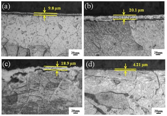
Figure 3.
The cross-sectional metallographic microscope (MM) images of Fe-Al-Cr alloyed layers under different sample temperatures: (a) 750 °C; (b) 800 °C; (c) 850 °C; (d) 900 °C.
3.2. The Effect of Gas Pressure on Microstructure of the Fe-Al-Cr Coating
During DGPSM process, gas pressure has a significant influence on the morphology and microstructure of the obtained Fe-Al-Cr coating. To understand the underlying mechanism, gas pressure was set as a variable (25, 35, 45, and 55 Pa), while the other parameters were set as follows: the voltage of source electrode (Vs = 850–950 V), the voltage of cathode (Vc = 450–550 V), the depositing time (t = 3.5 h), the sample temperature (T = 800 °C), and the electrode distance (d = 15 mm).
As shown in Figure 4a, when the gas pressure is 25 Pa, the obtained Fe-Al-Cr coating is not homogeneous, and some aggregated particles with sizes of around 4 μm can be observed. In contrast, the obtained Fe-Al-Cr coating is composed of uniform particles, with an average size of approximately 1.2 μm, when the gas pressure is 35 Pa (Figure 4b). However, when the gas pressure is increased to 45 Pa, aggregation of the deposited particles occurs, forming relatively large particles, with a size of 5.7 μm (Figure 4c). When the gas pressure is further increased to 55 Pa, no obvious coatings can be observed, and some very large particles with sizes of about 10 μm are deposited on the surface of the substrate, as shown in Figure 4d.
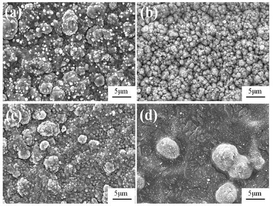
Figure 4.
The surface morphology of Fe-Al-Cr alloyed layers under different gas pressures: (a) 25 Pa; (b) 35 Pa; (c) 45 Pa; (d) 55 Pa.
Interestingly, when the gas pressure is 25 Pa, the Fe-Al-Cr coating exhibits a thickness of only 8.8 μm (Figure 5a). By contrast, when the gas pressure is increased to 35 Pa, a much thicker Fe-Al-Cr coating (22.5 μm) can be achieved (Figure 5b). However, the film thickness decreases to 10.2 and 5.1 μm when the gas pressure is further increased to 45 and 55 Pa, respectively (Figure 5c,d). Considering the surface morphology of the Fe-Al-Cr coatings shown in Figure 4, it is obvious that 35 Pa is the optimized parameter to achieve a high-quality Fe-Al-Cr coating. When the gas pressure is too low or too high, the quality of the obtained Fe-Al-Cr alloyed layer would be significantly reduced. This phenomenon can be well understood. When the gas pressure is too low (25 Pa), the concentration of the generated plasma is too low to bombard the source electrode [14]. As a result, the deposited alloyed source on the substrate is too deficient to form a uniform alloyed layer with a proper thickness. On the other hand, a higher gas pressure would increase the plasma concentration, causing a strong backscattering effect, which leads to a great number of alloyed particles in the coating being collided repeatedly by the plasma, and then moving from the coating back to the source electrode [15]. Owing to the escape of the alloyed atoms from the coating, the surface of the obtained coating is not uniform, and the thickness is significantly reduced.
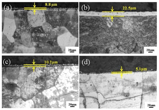
Figure 5.
The cross-sectional MM images of Fe-Al-Cr alloyed layers under different gas pressures: (a) 25 Pa; (b) 35 Pa; (c) 45 Pa; (d) 55 Pa.
3.3. The Effect of Electrode Distance on Microstructure of the Fe-Al-Cr Coating
To investigate the effect of electrode distance on the microstructure of the obtained Fe-Al-Cr coating, the electrode distance was set as a variable (10, 15, 20, and 25 mm), while the other parameters were set as follows: the voltage of source electrode (Vs = 850–950 V), the voltage of cathode (Vc = 450–550 V), the depositing time (t = 3.5 h), the temperature (T = 800 °C), and the gas pressure (P = 35 Pa).
As shown in Figure 6a, when the electrode distance is 10 mm, only isolated particles with sizes of around 0.8 μm are observed. By contrast, when the electrode distance is increased to 15 mm, numerous worm-like particles with an average size of 2 μm are grown, connecting with each other and thus forming a compact Fe-Al-Cr coating (Figure 6b). However, further increasing the electrode distance to 20 mm leads to a rough Fe-Al-Cr coating composed of aggregated particles (Figure 6c). When the electrode distance is further increased to 25 mm, the Fe-Al-Cr coating is not obvious, and the randomly distributed particles can be observed, as shown in Figure 6d.
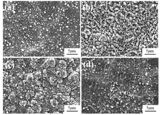
Figure 6.
The surface morphology of Fe-Al-Cr alloyed layers under different electrode distances: (a) 10 mm; (b) 15 mm; (c) 20 mm; (d) 25 mm.
As shown in Figure 7a, when the electrode distance is 10 mm, the thickness of the coating is 18.4 μm, and the interface between the substrate and the coating is very rough. When the electrode distance is increased to 15 mm, a compact Fe-Al-Cr coating with a thickness of 27.9 μm can be achieved (Figure 7b). However, Fe-Al-Cr coatings with a much thinner thickness of 16.7 and 4.8 μm are obtained when the electrode distance is further increased to 20 and 25 mm, respectively (Figure 7c,d). Therefore, the optimized electrode distance to achieve a high-quality Fe-Al-Cr coating is 15 mm. When the electrode distance is too short (10 mm), unequal potential hollow cathode discharge effect is very strong, leading to the overheating of the substrate and the source electrode [16]. As a result, burning loss of the Fe-Al-Cr coating takes place, forming discontinued coatings (Figure 6a and Figure 7a). On the other hand, when the electrode distance is larger than 15 mm, the unequal potential hollow cathode discharge effect is weaker, leading to the decrease of the current density from the source electrode [17]. As a result, the amount of the alloyed atoms sputtering from the source electrode decreases. In addition, the increase of the electrode distance will also increase the distance for the mass transport of the alloyed atoms, thus enhancing the loss of the alloyed atoms before depositing on the substrate [18]. Thus, the coating cannot form uniform morphology, and the thickness is significantly reduced.

Figure 7.
The cross-sectional MM images of Fe-Al-Cr alloyed layers under different electrode distances: (a) 10 mm; (b) 15 mm; (c) 20 mm; (d) 25 mm.
To further investigate the interfacial properties between the coatings and the Q235 steel substrates, the samples obtained at different electrode distances (10, 15, 20, and 25 mm, respectively) were characterized by SEM. As shown in Figure 8, thicknesses of the coatings are consistent with those shown in Figure 7, indicating that MM images are reliable to study the thickness of the obtained coatings. In addition, the coatings adhere very well to the Q235 steel substrates, as a result of the metallurgical bonding between the coatings and the Q235 steel substrates during DGPSM.

Figure 8.
The cross-sectional SEM images of Fe-Al-Cr alloyed layers under different electrode distances: (a) 10 mm; (b) 15 mm; (c) 20 mm; (d) 25 mm.
Overall, the desirable parameters of DGPSM to prepare high-quality Fe-Al-Cr alloyed coatings are as follows: sample temperature: 800 °C, gas pressure: 35 Pa, and electrode distance: 15 mm. In the further characterization and corrosion-resistance study, all the mentioned Fe-Al-Cr coatings were obtained under the abovementioned optimized conditions, unless stated otherwise.
3.4. The Elemental Distribution and Phase Analysis
As shown in Figure 9a, a uniform and dense Fe-Al-Cr coating with a thickness of approximately 25 μm was formed on the Q235 substrate, which can be divided into three layers, namely the outside deposited layer of about 5.5 μm, the middle compound layer with the thickness of around 15.5 μm, and the internal diffusion layer close to the substrate of 4 μm. It is obvious that the coating attached very well to the substrate, without any holes or other defects.
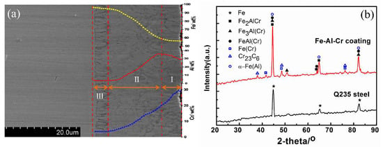
Figure 9.
(a) The cross-sectional morphology and composition distribution (I: deposited layer, II: compound layer, and III: diffusion layer), and (b) XRD patterns of Q235 and Fe-Al-Cr coating.
The Fe, Al, and Cr elements exhibit interesting distributions across the Fe-Al-Cr coating (inset in Figure 9a). During the process of double glow plasma metallurgy, Fe, Al, and Cr alloyed atoms in the source electrode were sputtered out by high-energy plasma, and then deposited on the surface of Q235 steel. The Cr element gradually decreased from 30 at.% at the surface of the deposited layer to around 3 at.% at the interface of the compound layer and diffusion layer, and then diffused into surface of the substrate, along the vacancy and dislocation defects, to form a diffusion layer. By contrast, the Fe element exhibited an opposition tendency, because the content of Fe in the source electrode was lower than that of the substrate, and the diffusion of Fe from the substrate to the Fe-Al-Cr coating also took place under the bombardment of high-energy plasma, leading to the gradual decrease of Fe element from the internal diffusion layer to the surface deposited layer. It is worth noting that the Al element increased slightly from the surface of the deposited layer up to 35 at.% at the surface of the compound layer, and then it decreased gradually to the diffusion layer. Since the temperature of plasma is much higher than the melting point of Al, the evaporation of Al in the deposited layer occurs during the double glow plasma metallurgy process [19], leading to the decrease of Al content from the interface of the compound layer and deposited layer to the surface of the deposited layer.
Figure 9b shows the XRD patterns of the Q235 steel and Fe-Al-Cr coating. Three characteristic peaks of Q235 can be observed. In comparison, three main peaks of Fe-Al-Cr were slightly shifted negatively, indicating the incorporation of Al and Cr elements that enlarge the lattice spacing. In addition, six new peaks can be observed, which can be assigned to Fe2AlCr, Fe3Al(Cr), FeAl(Cr), Fe(Cr), Cr23C6, and α-Fe(Al) [20,21,22]. According to the elemental distributions and the XRD results (Figure 9a,b), the outside deposited layer contains Fe2AlCr distributing in grain boundaries as the strengthening phase, while the middle compound layer is mainly composed of Fe3Al(Cr) and FeAl(Cr). Owing to the diffusion of Al and Cr into the Q235 steel substrate, Fe(Cr) solid solution, Cr23C6, and α-Fe(Al) are formed in the diffusion layer.
Figure 10 shows the SEM images and the EDS mapping of the Fe-Al-Cr coating. The film thickness is around 25 μm (Figure 10a), which is consistent to that shown in Figure 9a. It is clear that Al and Cr are mainly distributed in the Fe-Al-Cr coating (Figure 10b,c), while Fe is distributed in both the coating and the Q235 steel substrate (Figure 10d) [23,24]. The EDS mapping results confirm the successful deposition of the Fe-Al-Cr coating on the Q235 steel substrate by DGPSM.
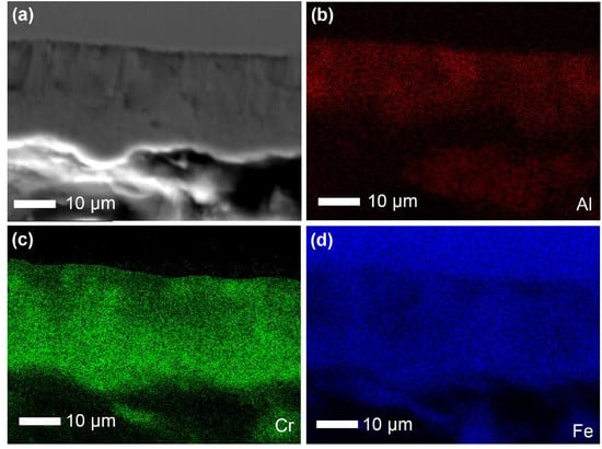
Figure 10.
(a) SEM image of the Fe-Al-Cr coating, and EDS mapping of (b) Al, (c) Cr, and (d) Fe.
3.5. Microhardness Test
The linear microhardness from surface to substrate of all samples is shown in Figure 11a–c. It can be seen that the Fe-Al-Cr coating can effectively increase the microhardness of the Q235 steel substrates. According to the cross-sectional view images shown in Figure 3, Figure 5 and Figure 7, it is obvious that the microhardness distributions are closely related to the thickness of the coatings obtained at different conditions. In addition, microhardness of the Q235 steel is only 175.2 HV0.1 (Figure 11d). With the deposition of a Fe-Al-Cr coating obtained under optimized conditions, the microhardness increases significantly to 460.3 HV0.1, which is approximately 2.5 times higher than that of the substrate. According to the XRD results, the enhanced microhardness is attributed to the formation of Fe3Al(Cr) and FeAl(Cr) intermetallic compounds with high hardness and strength [25,26]. In addition, the solid solution of Cr can further strengthen the hardness of Fe-Al intermetallic compounds at ambient temperature [27].
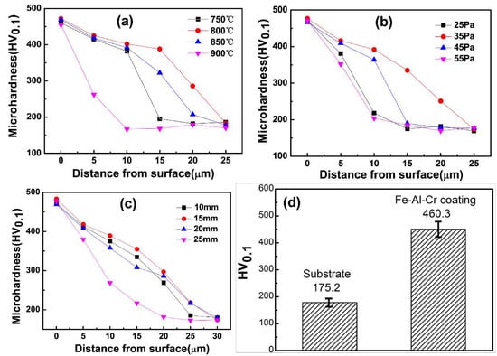
Figure 11.
(a–c) The microhardness distributions from the surface to the substrates of the Fe-Al-Cr coatings obtained at different parameters; (d) microhardness of the Q235 steel and Fe-Al-Cr coating.
3.6. Corrosion Resistance in a 0.5 mol/L H2SO4 Solution
Corrosion resistance of the obtained Fe-Al-Cr coating was investigated by anodic polarization curves and electrochemical impedance spectroscopy (EIS), in a 0.5 mol/L H2SO4 solution. For comparison, the anodic polarization and EIS curves of Q235 steel and 304 stainless steel were also measured. According to the anodic polarization curve of the Fe-Al-Cr coating shown in Figure 12a, when the potential is increased to −0.368 V, the Fe-Al-Cr coating is in the anodic dissolution region, leading to the obvious increase of current density with the increase of potential [28]. However, when the potential reaches −0.201 V, the current density is almost constant when the potential is increased, indicating that the Fe-Al-Cr coating is in the passivation stage [29]. Therefore, a passive layer is formed on the surface of the Fe-Al-Cr coating. The corresponding passive current density (ip) is 3.12 × 10⁻⁴ A/cm2. When the potential is higher than 0.152 V, the current density is significantly increased with the increase of the potential, indicating that the Fe-Al-Cr coating is in the transpassivation stage, and its rapid dissolution occurs [30]. By contrast, the 304 stainless steel shows a similar passivation phenomenon. However, the passivation region is not obvious. When the potential is increased to 0.5 V, a plateau occurs, indicating the formation of a passivation layer on the surface of the 304 stainless steel. The ip is 1.353 × 10⁻² A/cm2. When the potential is higher than 1.0 V, the current density increases dramatically. For bare Q235 steel, no obvious plateau can be observed, which indicates that the Q235 steel cannot form a passivation layer, and thus severe electrochemical corrosion takes place. According to the above analysis, the deposition of a Fe-Al-Cr coating on the surface of the Q235 steel can significantly increase its electrochemical corrosion resistance, which is even better than that of the 304 stainless steel. EIS curves of bare Q235 steel, 304 stainless steel, and Fe-Al-Cr coating are composed of only one semicircle (Figure 12b). The radius of the semicircle reflects the corrosion resistance of the sample [31]. It is obvious that the corrosion resistance of the Fe-Al-Cr coating is larger than that of the 304 stainless steel. However, the corrosion resistance of Q235 steel is much smaller compared to its Fe-Al-Cr coating and 304 stainless steel counterparts (inset in Figure 10b).
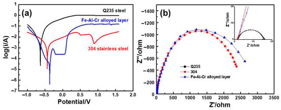
Figure 12.
(a) The anodic polarization curves; (b) EIS curves of samples in a 0.5 mol/L H2SO4 solution.
According to the anodic polarization curves shown in Figure 12a, the corrosion potential (Ecorr), corrosion current density (icorr), and passive current density (ip) of three samples were listed in Table 1. In addition, their corresponding polarization resistance values (Rp) were also calculated. As shown in Table 1, the icorr of Fe-Al-Cr is 8.623 × 10⁻⁵ A/cm2, which is much lower than those of its 304 stainless steel and Q235 steel counterparts. In addition, the Rp of Fe-Al-Cr is 985.4 Ω/cm2, which is much higher than those of its 304 stainless steel and Q235 steel counterparts. According to the icorr values, their corrosion rates were also calculated [32]. It is obvious that the corrosion rate of Fe-Al-Cr is only 0.66 mm/a, which is much lower than those of its Q235 steel and 304 stainless steel counterparts. Therefore, the Fe-Al-Cr coating exhibits excellent corrosion resistance in a 0.5 mol/L H2SO4 solution.

Table 1.
Calculation results of polarization curves of samples in a 0.5 mol/L H2SO4 solution.
The surface morphology and EDS patterns of bare Q235 steel, 304 stainless steel, and Fe-Al-Cr coating after electrochemical corrosion test in a 0.5 mol/L H2SO4 solution are shown in Figure 13. It is clear that the corrosion morphology of Q235 carbon steel is rough, and a hole with a diameter of around 5 µm and some corrosion products can be observed on the surface, indicating that Q235 carbon steel suffers severe corrosion (Figure 13a). According to the EDS analysis, the corrosion products are mainly iron oxide (Figure 13b). For the 304 stainless steel, numerous small pits can be observed on the surface (Figure 13c). The EDS pattern indicates the complexity of the corrosive products. In contrast, no obvious pits can be observed on the Fe-Al-Cr coating, even though the surface is rough (Figure 13e). Further analysis on its EDS pattern indicates that a stable and dense passivation film of chromium oxides is formed to block etching of the corrosive ions, exhibiting excellent corrosion resistance in the sulfuric acid solution.

Figure 13.
Corrosion morphology and EDS patterns of Q235 carbon steel (a,b), 304 stainless steel (c,d), and Fe-Al-Cr coating (e,f) after electrochemical corrosion in a 0.5 mol/L H2SO4 solution.
4. Conclusions
In summary, we have developed a DGPM technology for the deposition of a Fe-Al-Cr coating. Detailed investigations found that the optimized parameters are sample temperature: 800 °C, gas pressure: 35 Pa, and electrode distance: 15 mm. The obtained Fe-Al-Cr coating is metallurgically bonded with the substrate, which can be divided into three layers, namely the deposited layer, the compound layer, and diffusion layer from the surface to the substrate. The Fe-Al-Cr coating consists of Fe2AlCr, Fe3Al(Cr), FeAl(Cr), Fe(Cr) solid solution, Cr23C6, and α-Fe(Al), leading to an excellent microhardness that is 2.5 times higher than that of the Q236 steel substrate. Moreover, the Fe-Al-Cr coating can form a dense and stable passivation film in a 0.5 mol/L H2SO4 solution, which can effectively hinder the erosion of corrosive medium. As a result, the corrosion resistance of the Fe-Al-Cr coating is even better than that of the 304 stainless steel.
Author Contributions
Conceptualization, X.L.; methodology, X.L., P.Z. and H.X.; validation, X.L. and J.C.; formal analysis, X.L., J.C. and G.M.; investigation, X.L. and F.Y.; resources, X.L.; data curation, X.L. and Q.J.; writing—original draft preparation, X.L.; writing—review and editing, J.C., F.Y., Q.J., P.Z. and H.X.; supervision, P.Z. and H.X.; project administration, X.L. and H.X.; funding acquisition, X.L., Q.J. and H.X. All authors have read and agreed to the published version of the manuscript.
Funding
This research was funded by National Natural Science Foundation of China (Nos. 51871173 and 51801172), the fund of the State Key Laboratory of Advanced Processing and Recycling of Non-ferrous Metals, Lanzhou University of Technology (No. SKLAB02019003), the Natural Science Foundation of Shaanxi (Nos. 2020JQ-909 and 2019217314GXRC009CG010-GXYD9.1), the Undergraduate Innovation and Entrepreneurship Training Program (No. S201911736053), and the Scientific Research Program Funded by the Shaanxi Provincial Education Department.
Conflicts of Interest
The authors declare no conflict of interest.
References
- Hegazy, M.A.; El-Etre, A.Y.; El-Shafaie, M.; Berry, K.M. Novel cationic surfactants for corrosion inhibition of carbon steel pipelines in oil and gas wells applications. J. Mol. Liq. 2016, 214, 347–356. [Google Scholar] [CrossRef]
- Luo, X.X.; Yao, Z.J.; Zhang, P.Z.; Miao, Q.; Liang, W.P.; Wei, D.B.; Chen, Y. A study on high temperature oxidation behavior of double glow plasma surface metallurgy Fe-Al-Cr alloyed layer on Q235 steel. Appl. Surf. Sci. 2014, 305, 259–266. [Google Scholar] [CrossRef]
- Siddiqui, R.A.; Abdullah, H.A. Hydrogen embrittlement in 0.31% carbon steel used for petrochemical applications. J. Mater. Process. Technol. 2005, 170, 430–435. [Google Scholar] [CrossRef]
- Shmorgun, V.G.; Bogdanov, A.I.; Kulevich, V.P. The effect of aluminum content in the Fe-Cr-Al system alloys on the oxide films phase composition. Mater. Today: Proc. 2020, 10, 1016. [Google Scholar] [CrossRef]
- Luo, X.; Yao, Z.; Zhang, P.; Tao, X.; Chen, Y. Innovative method for preparation of Fe-Al-Cr intermetallic functionally graded material on 1045 steel with unique tribological properties. Surf. Rev. Lett. 2019, 26, 1850221. [Google Scholar] [CrossRef]
- Zhang, M.; Chen, C.; Zhang, G.; Rao, Y.; Ling, G. Preparation of Al-Cr-Fe coatings by heat treatment of electrodeposited Cr/Al composite coatings. Phys. Procedia 2013, 50, 206–213. [Google Scholar] [CrossRef]
- Cheng, W.J.; Wang, C.J. Growth of intermetallic layer in the aluminide mild steel during hot-dipping. Surf. Coat. Technol. 2009, 204, 824–828. [Google Scholar] [CrossRef]
- Cinca, N.; Guilemany, J.M. Thermal spraying of transition metal aluminides: An overview. Intermetallics 2012, 24, 60–72. [Google Scholar] [CrossRef]
- Wang, C.; Lin, Y.B.; Guo, X.Z.; Tao, J. Al2O3 reinforced Fe-Al composite coatings prepared by double glow discharge technique. Surf. Eng. 2013, 29, 572–579. [Google Scholar] [CrossRef]
- Yang, H.Q.; Yao, Z.J.; Luo, X.X.; Zhang, Z.L.; Chen, Y. Effect of Nb addition on structure and mechanical properties of feal coating. Surf. Coat. Technol. 2015, 270, 221–226. [Google Scholar] [CrossRef]
- Yuan, S.; Lin, N.; Zeng, Q.; Zhang, H.; Liu, X.; Wang, Z.; Wu, Y. Recent developments in research of double glow plasma surface alloying technology: A brief review. J. Mater. Res. Technol. 2020, 9, 6859–6882. [Google Scholar] [CrossRef]
- Lin, C.M.; Kai, W.Y.; Su, C.Y.; Tsai, C.N.; Chen, Y.C. Microstructure and mechanical properties of Ti-6Al-4V alloy diffused with molybdenum and nickel by double glow plasma surface alloying technique. J. Alloys Compd. 2017, 717, 197–204. [Google Scholar] [CrossRef]
- Xu, Z.; Liu, X.; Zhang, P.; Zhang, Y.; Zhang, G.; He, Z. Double glow plasma surface alloying and plasma nitriding. Surf. Coat. Technol. 2007, 201, 4822–4825. [Google Scholar] [CrossRef]
- Wu, W.; Chen, Z.; Lin, X.; Li, B.; Cong, X. Effects of bias voltage and gas pressure on orientation and microstructure of iridium coating by double glow plasma. Vacuum 2011, 86, 429–437. [Google Scholar] [CrossRef]
- Qiu, Z.; Zhang, P.; Wei, D.; Duan, B.; Zhou, P. Tribological behavior of CrCoNiAlTiY coating synthesized by double-glow plasma surface alloying technique. Tribol. Int. 2015, 92, 512–518. [Google Scholar] [CrossRef]
- Wei, D.; Zhang, P.; Yao, Z.; Zhou, J.; Wei, X.; Chen, X. Double glow plasma chromizing of Ti6Al4V alloys: Impact of working time, substrate-target distance, argon pressure and surface temperature of substrate. Vacuum 2015, 121, 81–87. [Google Scholar] [CrossRef]
- Wu, H.; Zhao, X.; Li, J.; Jiang, S.; Chen, Z. Effect of processing factors on the microstructure and gradual diffusion of tungstenized layers. Appl. Surf. Sci. 2019, 477, 232–240. [Google Scholar] [CrossRef]
- Ren, B.; Miao, Q.; Liang, W.; Yao, Z.; Zhang, P. Characteristics of Mo-Cr duplex-alloyed layer on Ti6Al4V by double glow plasma surface metallurgy. Surf. Coat. Technol. 2013, 228, S206–S209. [Google Scholar] [CrossRef]
- Zhu, X.L.; Yao, Z.J.; Gu, X.D.; Cong, W.; Zhang, P.Z. Microstructure and corrosion resistance of Fe-Al intermetallic coating on 45 steel synthesized by double glow plasma surface alloying technology. Trans. Nonferrous Met. Soc. China 2009, 19, 143–148. [Google Scholar] [CrossRef]
- Luo, X.; Yao, Z.; Zhang, P.; Zhou, K.; Wang, Z. Tribological properties of the Fe-Al-Cr alloyed layer by double glow plasma surface metallurgy. J. Mater. Eng. Perform. 2016, 25, 3938–3947. [Google Scholar] [CrossRef]
- Sourani, F.; Enayati, M.H.; Zhou, X.; Wang, S.; Ngan, A.H.W. Nanoindentation behavior of nanostructured bulk (Fe,Cr)Al and (Fe,Cr)Al-Al2O3 nanocomposites. J. Alloys Compd. 2019, 792, 348–356. [Google Scholar] [CrossRef]
- Vlasova, M.; Kakazey, M.; Mel’nikov, I.; Reséndiz-González, M.C.; Fironov, Y.; Ryabtsev, D.; Kondrashenko, S. Formation of CrxCyOz coatings under laser ablation of Cr23C6 ceramics. Surf. Coat. Technol. 2018, 349, 93–102. [Google Scholar] [CrossRef]
- Shiran, M.K.G.; Khalaj, G.; Pouraliakbar, H.; Jandaghi, M.R.; Dehnavi, A.S.; Bakhtiari, H. Multilayer Cu/Al/Cu explosive welded joints: Characterizing heat treatment effect on the interface microstructure and mechanical properties. J. Manuf. Process. 2018, 35, 657–663. [Google Scholar] [CrossRef]
- Si, C.; Duan, B.; Zhang, Q.; Cai, J.; Wu, W. Microstructure, corrosion-resistance, and wear-resistance properties of subsonic flame sprayed amorphous Fe-Mo-Cr-Co coating with extremely high amorphous rate. J. Mater. Res. Technol. 2020, 9, 3292–3303. [Google Scholar] [CrossRef]
- Skorodzievskii, V.S.; Ustinov, A.I.; Polishchuk, S.S.; Demchenkov, S.A.; Telychko, V.O. Dissipative properties of Al-(Fe, Cr) vacuum coatings with different composite structures. Surf. Coat. Technol. 2019, 367, 179–186. [Google Scholar] [CrossRef]
- Luo, X.; Cao, J.; Meng, G.; Chuan, Y.; Yao, Z.; Xie, H. Systematical investigation on the microstructures and tribological properties of Fe-Al laser cladding coatings. Appl. Surf. Sci. 2020, 516, 146121. [Google Scholar] [CrossRef]
- Senčekova, L.; Palm, M.; Pešička, J.; Veselý, J. Microstructures, mechanical properties and oxidation behaviour of single-phase Fe3Al (D03) and two-phase α-Fe,Al (A2)+Fe3Al (D03) Fe-Al-V alloys. Intermetallics 2016, 73, 58–66. [Google Scholar] [CrossRef]
- Li, J.; Lin, X.; Wang, J.; Zheng, M.; Guo, P.; Zhang, Y.; Ren, Y.; Liu, J.; Huang, W. Effect of stress-relief annealing on anodic dissolution behaviour of additive manufactured Ti-6Al-4V via laser solid forming. Corros. Sci. 2019, 153, 314–326. [Google Scholar] [CrossRef]
- Etminanfar, M.R.; Khalil-Allafi, J.; Sheykholeslami, S.O.R. The effect of hydroxyapatite coatings on the passivation behavior of oxidized and unoxidized superelastic nitinol alloys. J. Mater. Eng. Perform. 2018, 27, 501–509. [Google Scholar] [CrossRef]
- Bellezze, T.; Giuliani, G.; Roventi, G. Study of stainless steels corrosion in a strong acid mixture. Part 1: Cyclic potentiodynamic polarization curves examined by means of an analytical method. Corros. Sci. 2018, 130, 113–125. [Google Scholar] [CrossRef]
- Cai, D.; Han, S.; Zheng, S.; Luo, Z.; Zhang, Y.; Wang, K. Microstructure and corrosion resistance of Al5083 alloy hybrid plasma-mig welds. J. Mater. Process. Technol. 2018, 255, 530–535. [Google Scholar] [CrossRef]
- García-Rodríguez, S.; Torres, B.; Pulido-González, N.; Otero, E.; Rams, J. Corrosion behavior of 316L stainless steel coatings on ZE41 magnesium alloy in chloride environments. Surf. Coat. Technol. 2019, 378, 124994. [Google Scholar] [CrossRef]
© 2020 by the authors. Licensee MDPI, Basel, Switzerland. This article is an open access article distributed under the terms and conditions of the Creative Commons Attribution (CC BY) license (http://creativecommons.org/licenses/by/4.0/).