Article

Design of a Double-Nozzle Air Spray Gun and Numerical Research in the Interference Spray Flow Field

School of Mechanical and Automotive Engineering, South China University of Technology, 381 Wushan Road, Guangzhou 510641, China
*
Author to whom correspondence should be addressed.
Coatings 2020, 10(5), 475; https://doi.org/10.3390/coatings10050475
Submission received: 20 March 2020 / Revised: 10 May 2020 / Accepted: 12 May 2020 / Published: 14 May 2020

Abstract

:
Spray painting robots equipped with air spray guns have been widely used in the painting industry. In view of the low efficiency of single-nozzle air spray guns when spraying large targets, a new double-nozzle air spray gun structure was designed in this paper based on the Coanda effect of double jets. Firstly, a 3-D physical model of the double-nozzle air spray gun was built in Solidworks, in which unstructured grids were generated for the computational domain by ICEM. Secondly, the spray painting process was numerically modeled with the help of the computational fluid dynamics (CFD) software ANSYS-Fluent 16.0. The two-phase spray flow was calculated by coupling a discrete phase model (DPM) and the Taylor analogy breakup (TAB) method. The TAB model was applied to predict the secondary break-up. The DPM model was applied to predict the droplet trajectories. The geometry of an air spray gun has a significant influence on the spray flow field characteristics. The influence of the air spray gun geometry on the interference spray flow field characteristics and coating film thickness distribution were investigated by changing the values of the distance between the centers of the two paint holes (L) and the angle between the axes of the two paint holes (θ). Numerical results show that the smaller L and θ are, the stronger the interference effect between the two jets, while the more concentrated the paint is in the central region of the target surface, the easier it is for overspray to occur. With increasing L and θ, the interference effect gradually decreased and the extension distance of the coating film along the x-axis gradually increased. However, if L and θ are too large, the interference effect will become too weak and the shape of the coating film will become a concave, with more paint on both side regions and less paint in the central region, which will cause an uneven coating film. From the simulation results, it can be concluded that a more uniform coating film can be obtained when L = 30 mm and θ = 10°. The effective coating width of the double-nozzle air spray gun was increased by 85.7% compared with the single-nozzle air spray gun, which improved the spraying efficiency.

1. Introduction

In order to obtain high-quality coatings, painting robots with air spray guns have been widely used in the painting industry, with applications in the automobile, ship, airplane, furniture, and many other industries [1,2,3]. Air spray guns have attracted wide attention due to their good atomization performance. However, the establishment of coating deposition models and the planning of spray gun trajectories are still difficult problems to be solved. Inappropriate coating deposition models and spray gun trajectories would lead to bad uniformity of the coating film, and thus poor quality products [4]. In addition, low spraying efficiency occurs when a spraying robot is used for large targets.
Teaching and offline programming methods have been widely used in spray gun trajectory planning for painting robots. The teaching programming method is not flexible and the coating quality obtained by this method largely depends on operator’s experience, which makes it hard for the coating uniformity to meet precise criteria. Therefore, in order to solve these problems, many researchers have studied offline programming techniques to plan spray gun trajectories for painting robots [5,6,7,8,9]. The establishment of a coating deposition model is a significant part of an offline programming method for painting robot. Therefore, the accuracy of the simulation of coating film thickness distribution is very important for coating quality. Many methods have been applied in simulations. Earlier researchers used an explicit function-based method to fit the distribution curves of coating thickness. The typical examples include the parabolic distribution model [10,11], piecewise distribution model [12,13], Cauchy distribution model [14], Gaussian distribution model [15], β distribution model [16], and ellipse dual-β distribution model [17]. These models are based on specific spray guns, which would lead to problems of model invalidation and uneven coating when the spray gun parameters are changed. The explicit function-based method cannot describe the spraying process and the coating formation mechanism.
With the development and wide application of computational fluid dynamics (CFD) technology, many researchers have used CFD-based methods to simulate coating thickness distribution. CFD-based methods can not only analyze the coating formation mechanism, but can also obtain the precise distribution of coating thickness under various operating conditions, which is more accurate than explicit function-based methods and can better reflect the real situation of the painting process. Therefore, CFD-based methods will be popular for coating thickness simulation in the future [18]. The painting process includes three subprocesses: the atomization process, droplet transportation process, and coating film formation process. The atomization process can be divided into two parts: primary breakup and secondary breakup. CFD-based method describes the painting process as a gas–liquid two-phase flow. The Euler–Lagrange method and Euler–Euler method have been applied previously to model the two-phase flow field.
In recent years, some experimental and numerical investigations [19,20,21,22,23,24,25,26,27] on the painting process have been conducted using the Euler–Lagrange method, focusing mainly on the droplet size distribution, the influences of spray gun geometry and air flow, on coating thickness distribution, as well as on droplet impingement. In the Euler–Lagrange method, the air is treated as a continuous phase and the droplets are treated as a discrete phase. Ye et al. [22,23] and Domnick et al. [24,25] applied experiment-based methods to obtain the initial conditions of the discrete phase in order to calculate the spray flow field. The discrete phase information, including the droplet size and velocity distribution, were measured at a certain position below the spray gun with the help of a phase doppler analyzer (PDA). They directly analyzed the experimental data at a position very close to the spray gun. However, complex, time-consuming, and expensive experiments must be carried out again once the operating parameters of this method are changed. Fogliati et al. [27] applied the VOF model to simulate the paint jet at the exit point of the spray gun and obtained the initial droplet conditions. However, they did not consider the secondary breakup of droplets.
In the Euler–Euler method [4,28], both air and droplets are considered as continuous phases and are calculated in Euler coordinates. Numerical simulation based on the Euler–Euler method does not require tracking of large quantities of droplets as in the Euler–Lagrange method, saving computing resources. Chen et al. [4] proposed a numerical simulation method based on a dynamic grid model to calculate the coating thickness distribution. However, in the air painting process, the paint flow is about 300 mL/min and the gas flow is about 100 L/min. The Euler–Euler method is not suitable for spare droplet distribution.
So far, the research on air spray guns has focused on single-nozzle guns. In order to improve the spraying efficiency, a new double-nozzle air spray gun model is proposed in this paper. The DPM–TAB coupling method is applied to model the two-phase flow spraying process with the help of the Fluent 19.0 commercial CFD code. The TAB model is used to simulate the secondary breakup process and the DPM model is used to predict the droplet trajectory. The interference spray flow field of the double-nozzle air spray gun is numerically studied by changing the L and θ values. The influence of the spray gun geometry on coating thickness distribution is also analyzed.

2. Computational Model

2.1. Geometry of the Double-Bozzle Air Spray Gun

The geometry of the air cap of the double-nozzle air spray gun proposed in this paper is shown in Figure 1. There are 2 paint holes, 2 annular atomizing air holes, 8 assisting air holes, and 8 shaping air holes on the air cap. The central paint holes have a 1.5 mm diameter and are surrounded by atomizing air holes with an outer diameter of 2.5 mm and inner diameter of 2 mm. The high-speed atomizing airflow breaks the liquid paint into small droplets and transports the droplets to the target surface. In addition to the annular atomizing holes, there are 8 assisting air holes measuring 0.5 mm in diameter. Assisting air flow can not only control the expansion speed of the spray flow field but also keep the surface clean. On both sides of the air cap, there are 8 shaping air holes measuring 1.5 mm in diameter. The shaping air flow can deform the spray flow field, meaning a narrow elliptical coating film can be formed on the target. L is the distance between the centers of two paint holes and θ is the angle between the axes of the two paint holes. L and θ influence the spray flow field characteristics and coating thickness distribution.
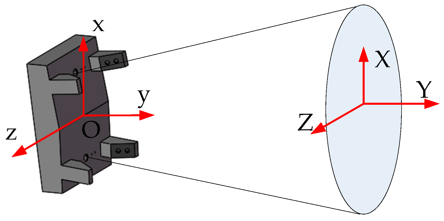
Figure 2 illustrates the coordinate system of the air spray gun. The midpoint O of the line connecting the centers of the two paint holes is the origin of the coordinate system. The y axis is parallel to the axis of the double-nozzle air spray gun. The x axis is parallel to the long axis of the coating X and the z axis is parallel to the short axis Z.

2.2. Computational Domain and Grid

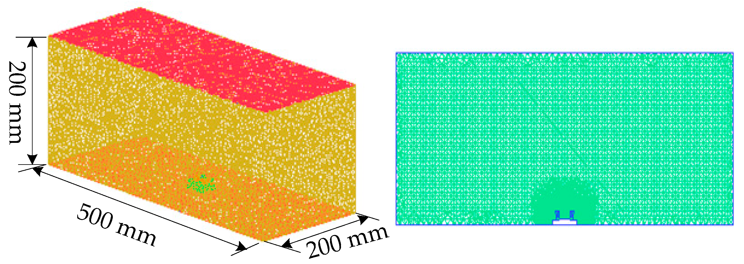
The computational domain and grid of the air spray gun are shown in Figure 3. Considering the characteristics of the spray flow field and the elliptical shape of the coating deposition, a cuboid computational domain with a size of 500 × 200 × 200 mm3 was used in this paper. The air cap is located at the center of the under surface and the target surface is located at the top of the computational domain. The spraying distance (distance from paint hole to target surface) is 190 mm. An unstructured grid with 1.85 million cells was used in this paper with the help of ICEM, because it can better fit the complex geometry of the computational domain. A local grid refinement method was used to ensure the accuracy of computation and reduce the consumption of computing resources. The grid of the region close to the air spray gun was refined to accurately simulate the interaction between air and droplets. The region far away from the air spray gun had a lower grid resolution to limit the total number of cells. The details of the structure of the grid are shown in Figure 3.

2.3. Numerical Method and Initial Conditions

The high-speed air flow atomized the paint into fine droplets. The droplets were transported onto the target surface under the action of air flow, thus forming a coating film. The spray flow field can be regarded as a gas–liquid two-phase flow field. The DPM method is a multiphase flow model based on the Euler–Lagrange method, which was applied to simulate the spraying process. The air phase (continuous phase) was calculated in the Euler coordinate system. The droplets phase (discrete phase) was calculated in the Lagrange coordinate system. The finite volume method was applied for the numerical simulations with the help of the ANSYS-Fluent 16.0 commercial CFD software. A pressure–velocity coupled solver, transient method, and unsteady particle tracking were used for simulation. The turbulent flow field was modeled using the realizable k ε model. The effect of the turbulence dispersion on the droplet motion was simulated by using a stochastic tracking model. An Eulerian film model was used to calculate the distribution of the coating film thickness. The total spraying time was 0.4 s. The start time of the injection of the discrete phase was 0.1 s and the stop time was 0.3 s. The time step size was 1 × 10⁻³ s. The convergence conditions were that the velocity, pressure, k, and ε residuals were less than 1 × 10⁻⁴. We also checked whether the whole system satisfied the principle of mass conservation. When the unbalanced error was less than 0.1%, the numerical results were considered to be convergent.
In the Lagrange coordinate system, the droplet trajectories were calculated by integrating the equation of motion of the discrete phase. The equation of motion is:
d u p d t = F D ( u u p ) + F G
in which F D ( u u p ) is the drag force per unit particle mass; F G is the gravity force per unit particle mass; u p is the droplet velocity; u is the instantaneous air velocity, which is obtained by superimposing the local mean velocity and the fluctuating velocity caused by turbulence. The equation of motion is obtained by the force balance on the droplet. Because the density of air is much less than the density of droplets, the Saffman’s lift and virtual mass force may be neglected. The interaction between droplets may be neglected since the mass flow rate of the paint is relatively low.
An air phase and a droplet phase were defined in the spray flow field. Simplified inlet boundary conditions for both the continuous phase and discrete phase were used in this paper. All paint holes were set as mass flow inlets, with a mass flow rate of 1.5 × 10⁻³ kg/s and an initial velocity of 5 m/s. All air holes were set as pressure inlets. The surface of the air spray gun and the upper surface of the computational domain were set as walls. The other surfaces of the computational domain were set as pressure outlets, with gauge pressure of 0 MPa. The major parameters of the gun and the important properties of the materials are summarized in Table 1 and Table 2.
The size distribution of the particles is usually obtained by experiments, which are expensive and time-consuming. In order to reduce the dependence of numerical simulation on experiments, droplets measuring 65 μm in diameter were directly injected into the air flow field in the paint hole positions. The TAB (Taylor analogy breakup) model was used to predict the secondary breakup of droplets.

3. Simulation Results and Discussion

3.1. Setting of Structural Parameters

A new double-nozzle air spray gun was proposed in this paper. The influence of the structural parameters on the interference flow field characteristics and coating film thickness distribution was studied by selecting L and θ as variables. The values of L and θ are shown in Table 3.

3.2. Grid Independence Study

During the numerical simulation, the quality of the grid will affect the accuracy of the calculation. In addition, the more cells, the longer the calculation time. In order to eliminate the effect of the number of cells on the calculation results and determine the optimal number of cells for calculation, the grid independence was studied.
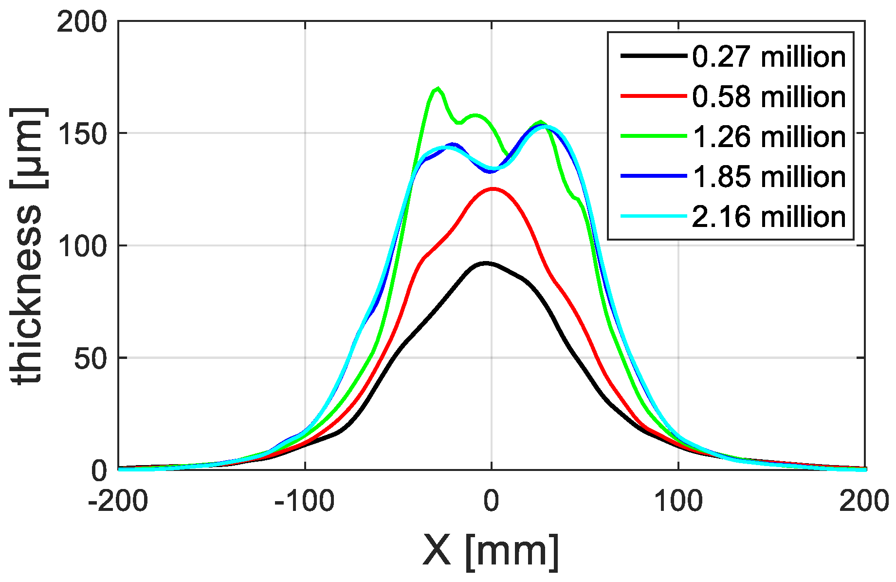
In order to conduct the studies on grid independence, five kinds of grids were generated, with 0.27, 0.58, 1.26, 1.85, and 2.16 million cells. The simulation parameters are shown in Table 1 and Table 2. The double-nozzle spray gun with structural parameters of L = 30 mm and θ = 10° was selected. Figure 4 displays the influence of the number of cells on the coating thickness distribution along the x-axis. When the number of cells is small, the results are related to the number of cells. When the number of cells is greater than 1.85 million, the coating thickness distribution profiles along the x-axis remain basically unchanged, which indicates that the simulation results are convergent. The results are independent of the number of cells. In this paper, a grid with 1.85 million cells was selected for calculation.

3.3. Simulation Results of the Velocity Field

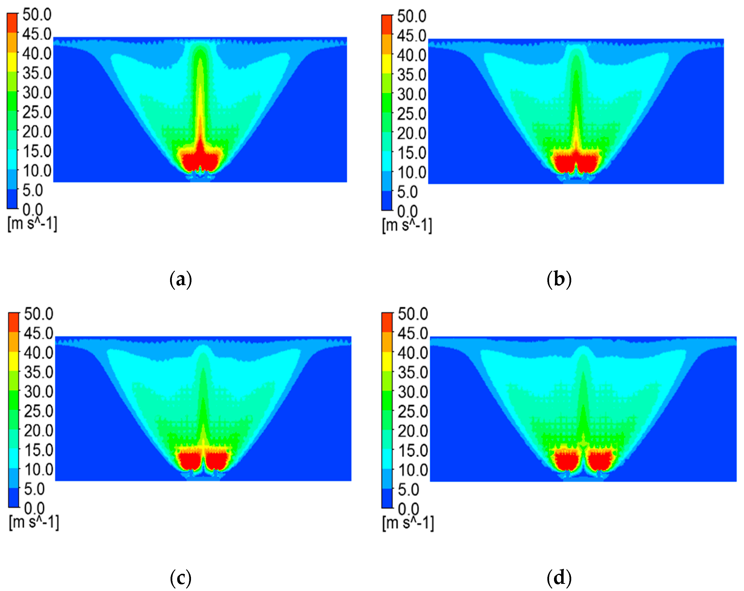
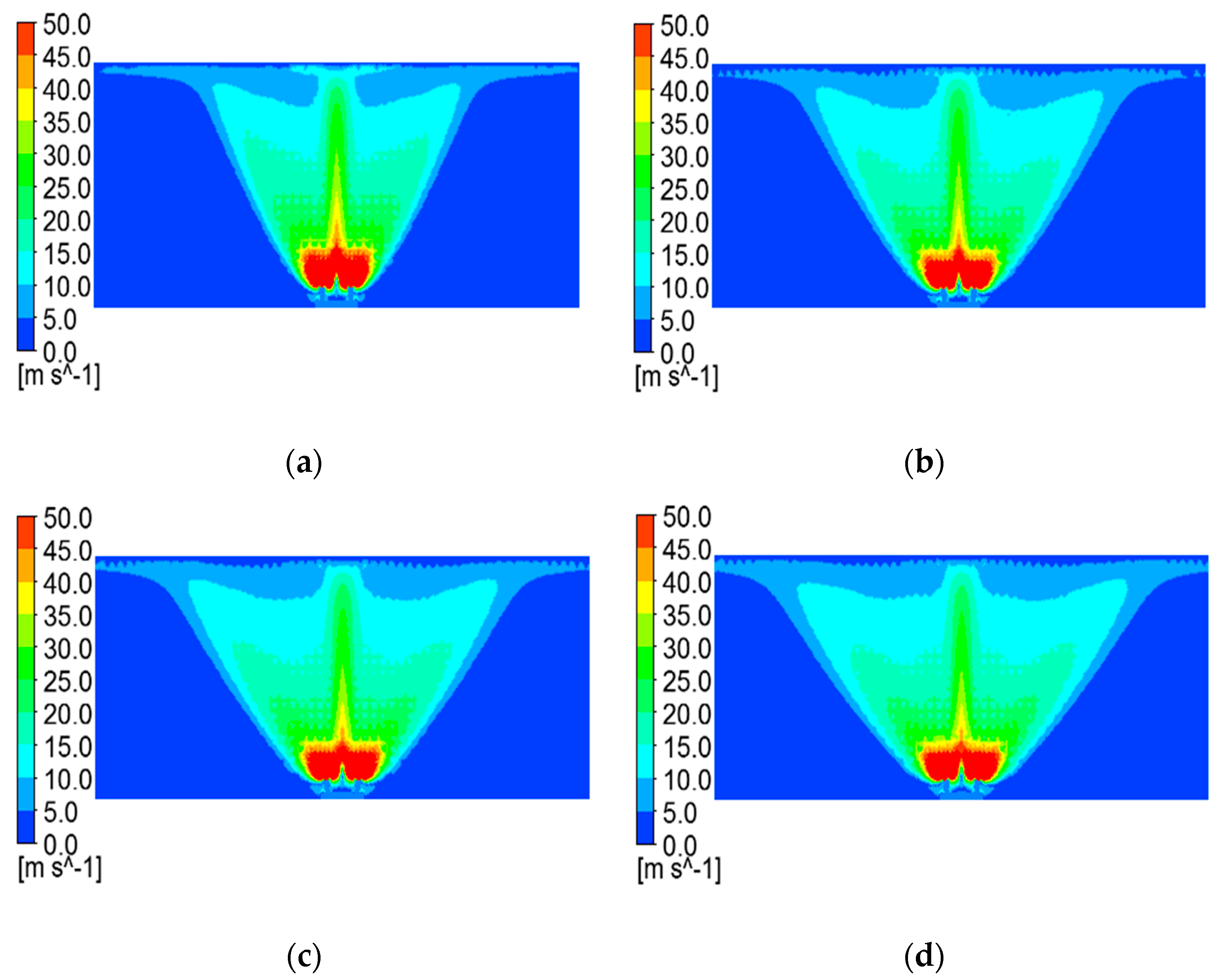
Figure 5 displays the velocity contours at section z = 0 for different L when θ = 10°. For easier viewing of the whole velocity field, the maximum visible velocity was set to 50 m/s. There is a larger velocity near the air spray gun, which then decreases rapidly along the y direction. Negative pressure was generated in the region between the two jets due to the entrainment of the jets, which made the jets attract each other. Finally, the two jets combined into one jet. This effect of two jets is called the Coanda effect. The combined jet has a larger velocity in the region near the central axis. The simulation results indicate that the larger the L is, the greater the width of the velocity field.
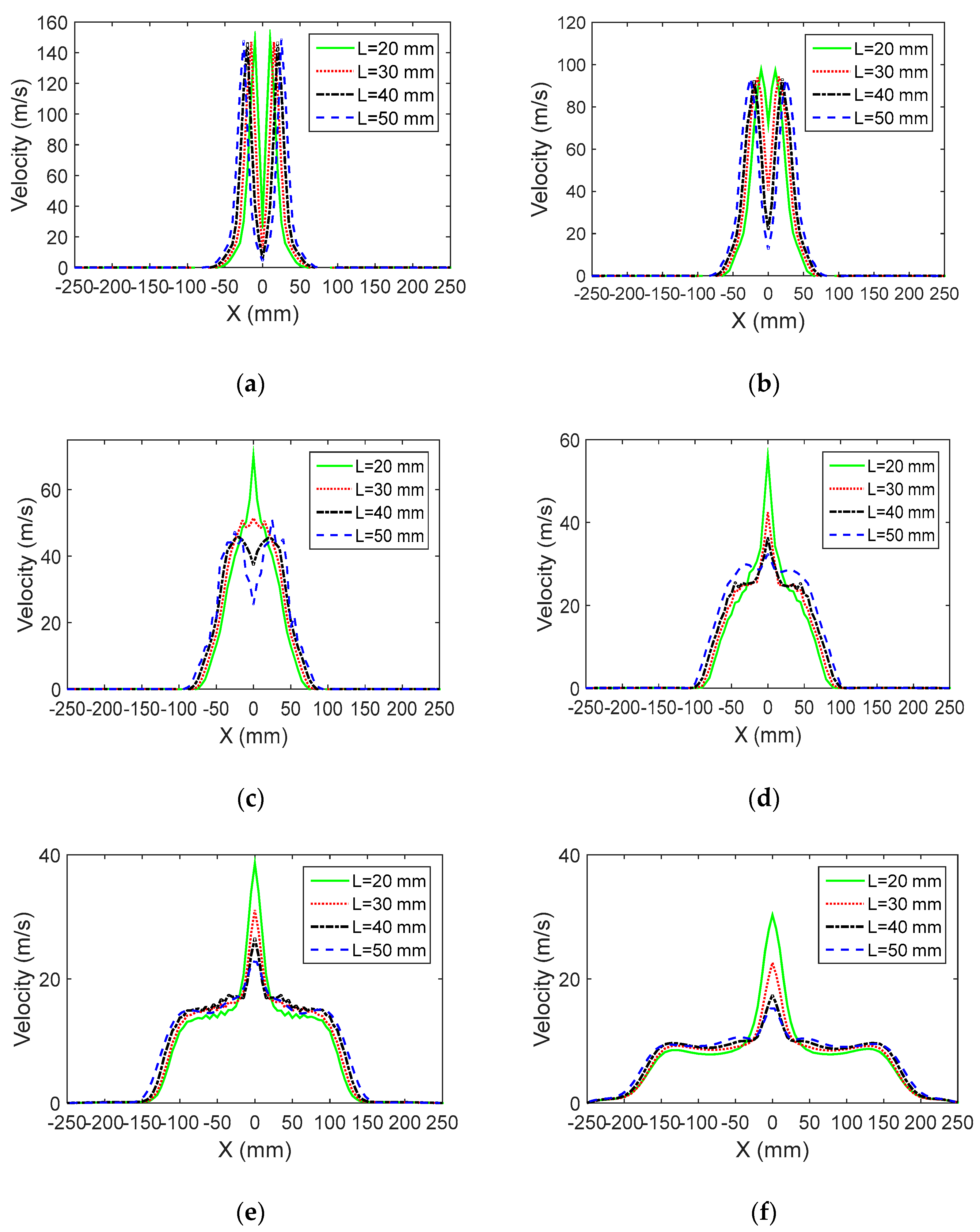
In this paper, six cross-sections were chosen sequentially along the y-axis direction: y = 15 mm, y = 25 mm, y = 35 mm, y = 50 mm, y = 100 mm, y = 170 mm. Figure 6 depicts the velocity profiles for each cross-section in the plane z = 0. From Figure 6a,b, it is found that the velocity profile has two peaks; cross-section y =25 mm resembles cross-section y = 15 mm, but the peak values of cross-section y = 25 mm are smaller than cross-section y = 15 mm, which shows the Gaussian distribution around these peaks. Figure 6c indicates that the two peaks have been combined into one peak near the cross-section y = 35 mm; the bigger L is, the greater the distance from the position where the two peaks begin combine into one peak to the spray gun. From Figure 6d–f, it is found that the velocity profiles of cross-section y = 50 mm, y = 100 mm, and y = 170 mm are similar to each other, which reflect the self-similarity behavior of the jets. The peak values decrease gradually along the flow direction, which reveals that the entrainment effect of the jet causes the consumption of momentum. Simulation results show that the larger L is, the smaller the velocity near the central axis, and the greater the velocity far away from the central axis.
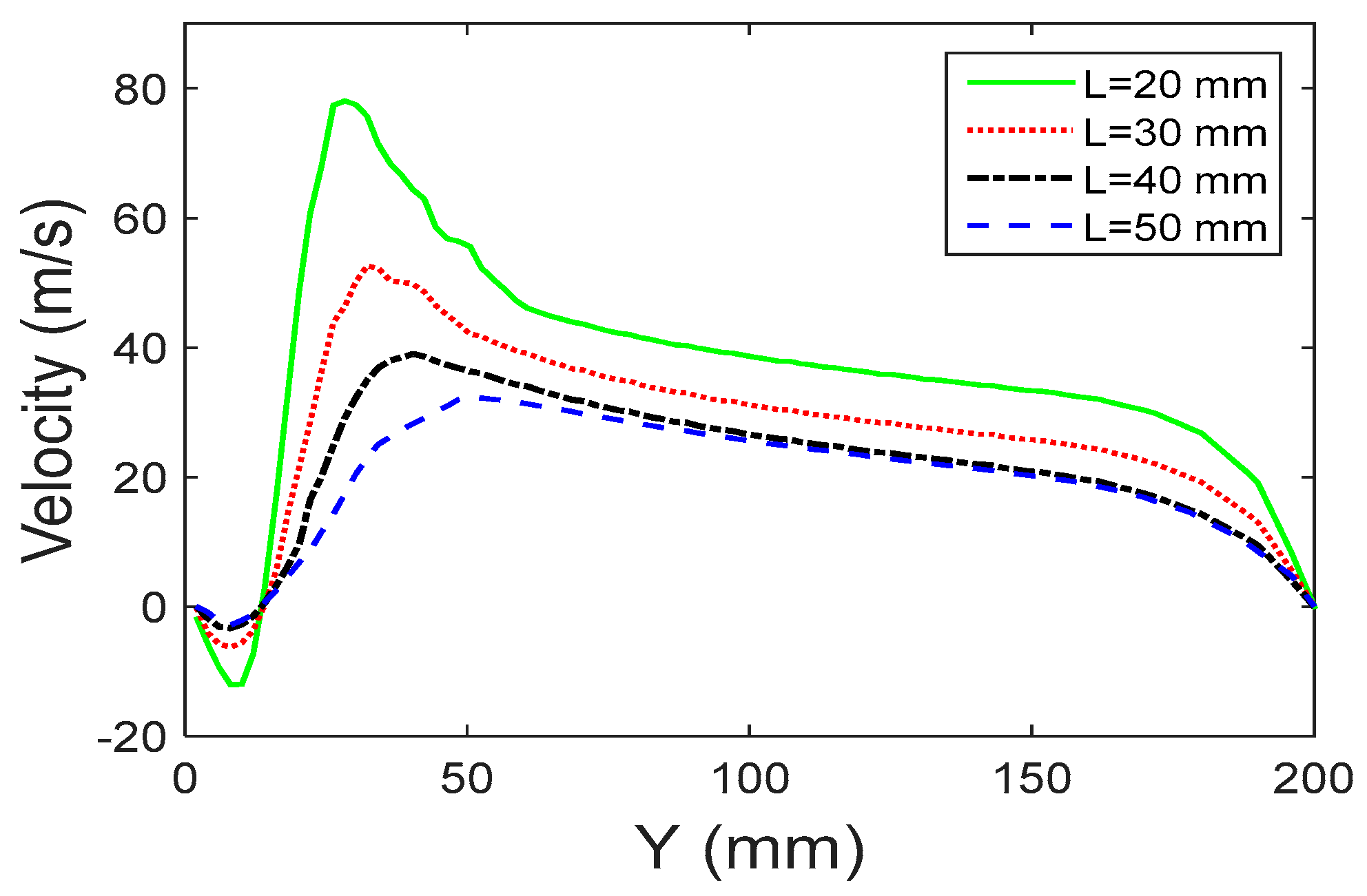
The velocity profiles along the central axis for different L are shown in Figure 7. Due to the effect of turbulence flow, each jet entrains the surrounding air and flow downstream. Negative pressure was generated in the region between the two jets due to the entrainment of the jets, which makes the jets attract each other. Finally, the two jets combine into one jet. A recirculation zone was formed before the confluence point. There is a point with velocity of 0, where the velocity changes direction, before which the velocity is negative and after which the velocity becomes positive and rapidly increases to the maximum value. Then the velocity decreases slowly and tends towards zero. It is obvious that the larger the L is, the greater the absolute value of velocity.
Figure 8 displays the velocity contours at section z = 0 for different θ when L = 30 mm. The maximum visible velocity was set to 50 m/s. There is a larger velocity near the air spray gun and then the velocity decreases rapidly along the y direction. The combined jet has a larger velocity in the region near the central axis. The simulation results indicate that the larger the θ is, the greater the width of the velocity field.
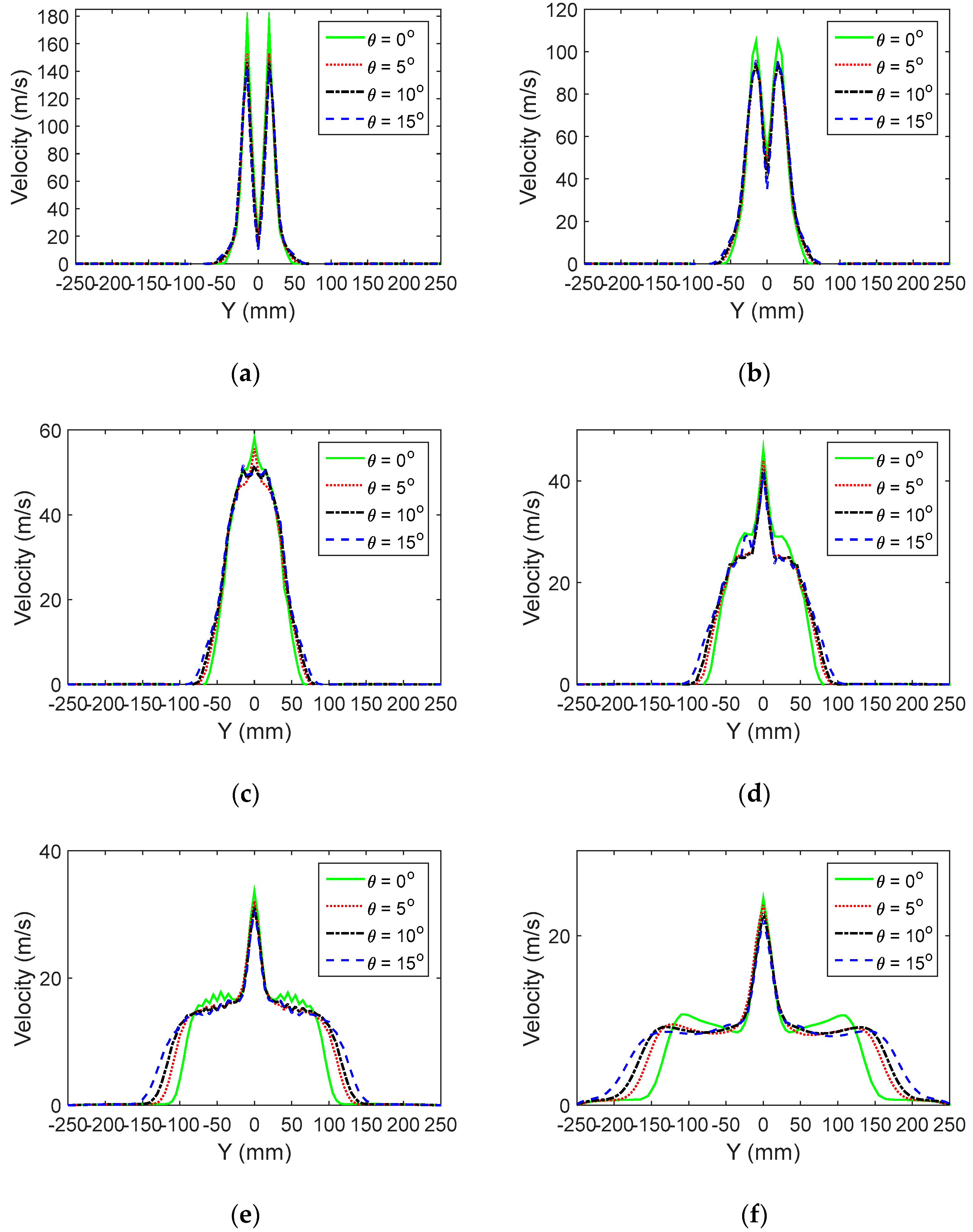
Figure 9 depicts the velocity profiles for each cross-section in the plane z = 0 when L = 30 mm. It is obvious that Figure 9b resembles Figure 9a, the velocity profile has two peaks, and the peak values of cross-section y = 25 mm are smaller than for cross-section y = 15 mm. Figure 9c indicates that the two peaks have been combined into one peak near the cross-section y = 35 mm; the larger the θ is, the greater the distance from the position where the two peaks begin combine into one peak towards the gun. From Figure 9d–f, it is found that the peak values of the combined jet decrease gradually along the flow direction; the larger θ is, the smaller the velocity near the central axis and the greater the velocity far away from the central axis.
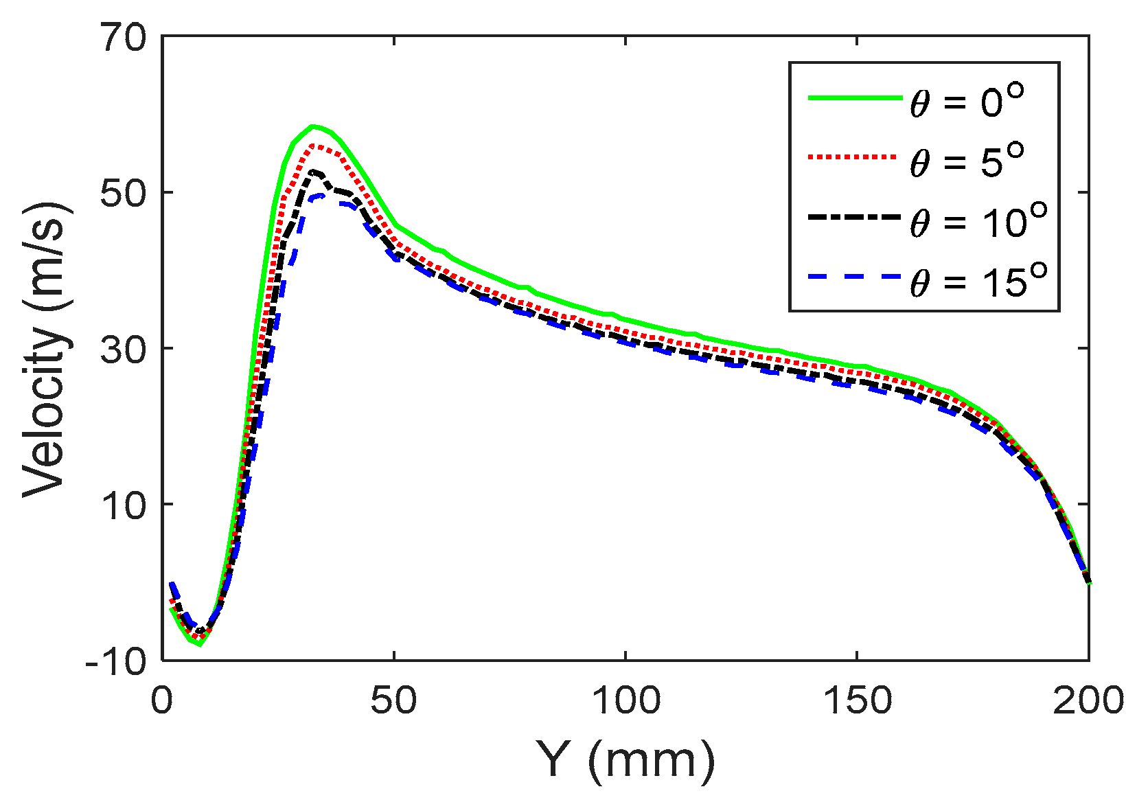
The velocity profiles along the central axis for different θ are shown in Figure 10. There is a point with velocity of 0, before which the velocity is negative and after which the velocity becomes positive and rapidly increases to the maximum value. Then, the velocity decreases slowly and tends towards zero. The larger θ is, the greater the absolute value of velocity.
The effects of L and θ on the interference flow field are similar to each other. The smaller the L and θ are, the greater the interference effect is. The interference flow field has a great influence on the coating thickness distribution. Therefore, it is possible to obtain a uniform coating film by adjusting the L and θ.

3.4. Simulation Results of the Coating Film Thickness Distribution

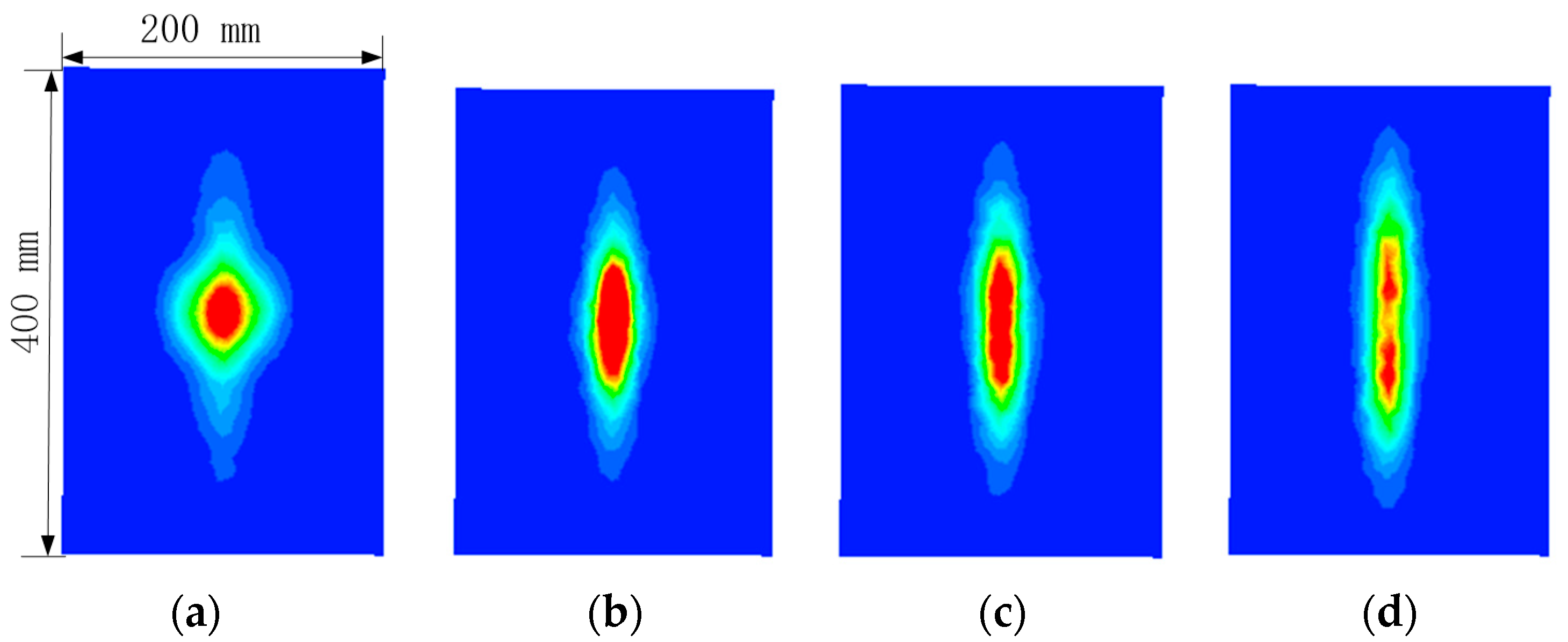
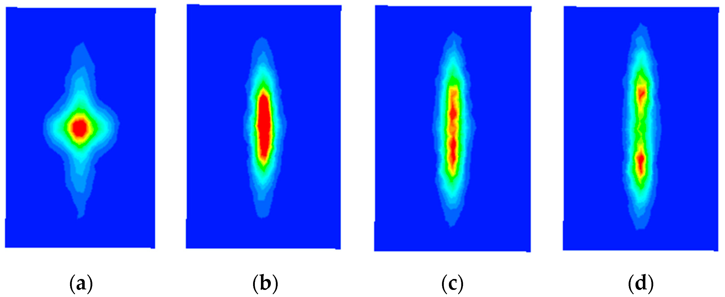
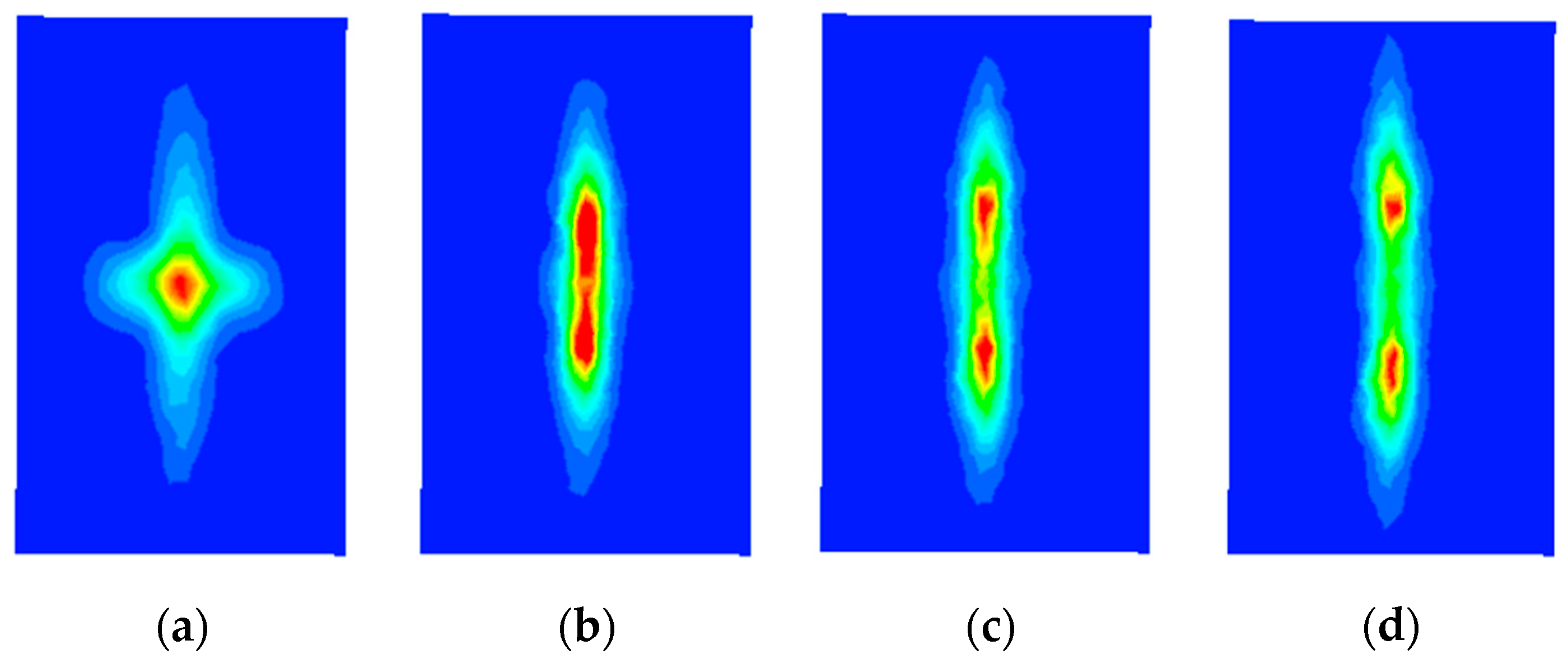
Figure 11, Figure 12 and Figure 13 show the coating film thickness distribution contours. It is obvious that when L is fixed, with increasing θ, the extension distance of the coating film along the x-axis (long axis) gradually increases and the shape of the coating film becomes an ellipse. The larger θ is, the greater the extension distance along the x-axis and the smaller the extension distance along the z-axis (short axis). Similarly, when θ is fixed, the larger L is, the greater the extension distance along the x-axis and the smaller the extension distance along the z-axis. From Figure 11a, Figure 12a, and Figure 13a, it can be seen that the shape of the coating film is a rhombus and the paint is more concentrated in the central region of the target surface, which easily causes overspray.
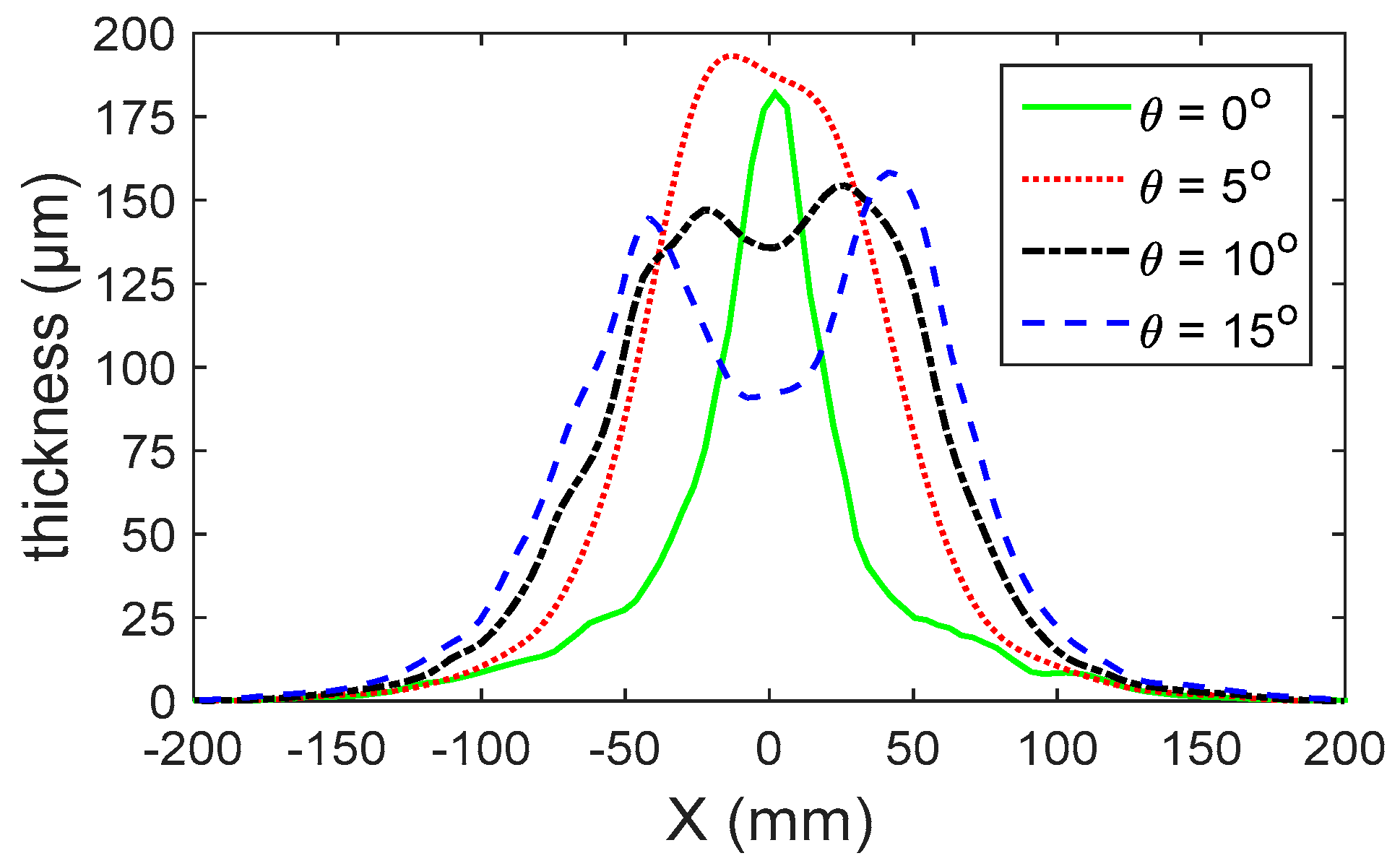
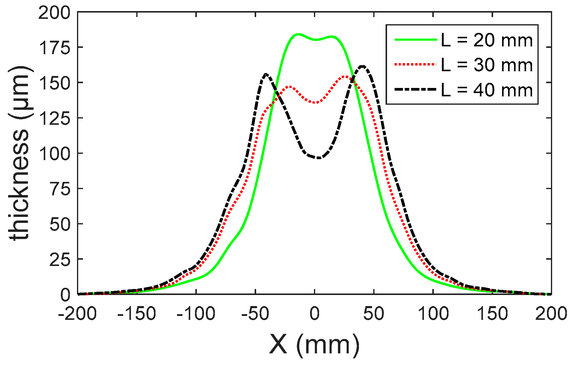
Figure 14 indicates the coating film thickness profiles along x for different θ values when L = 30 mm. The coating thickness along the x-axis near the central area when θ = 0° is greater than the coating thickness when θ = 5°. The reason for this phenomenon is that the interference effect of the two jets is very strong and the combined jet diffuses along the z-axis direction when θ = 0°, which causes part of the droplets to be transported in the z-axis direction and the shape of the coating film to become a rhombus. The shape of the coating film becomes concave when θ = 15°; the reason for this phenomenon is that the interference effect of the two jets is weak and fewer droplets are transported to the central region, which results in more paint on both side regions and less in the central region. Figure 15 indicates the coating film thickness profiles along the x-axis for different L values when θ = 10°. It is obvious that the paint is more concentrated in the central region of the target surface when L = 20 mm; the shape of the coating film becomes concave, with more paint in both side regions and less paint in the central region. The effects of L and θ on the coating thickness distribution are similar to each other. The smaller L and θ are, the stronger the interference effect is, the more concentrated the paint is in the central area of the target surface. However, if L and θ are too large, the interference effect will be too weak and the shape of the coating film will become a concave, which will also easily cause an uneven coating film. From the simulation results, it can be seen that a uniform coating film can be obtained when L = 30 mm and θ = 10°.

3.5. Comparison of Double-Nozzle and Single-Nozzle Air Spray Guns

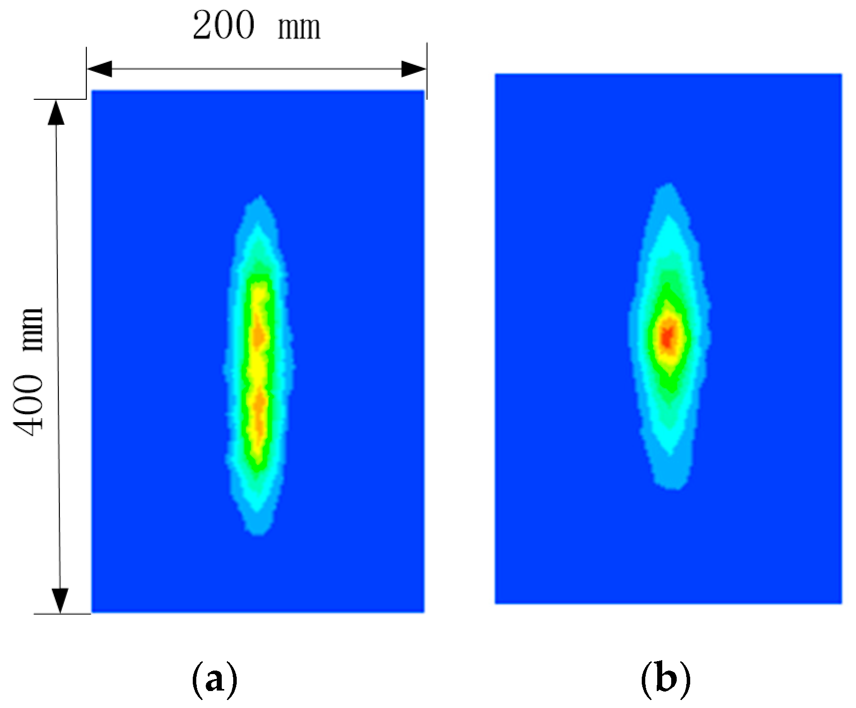
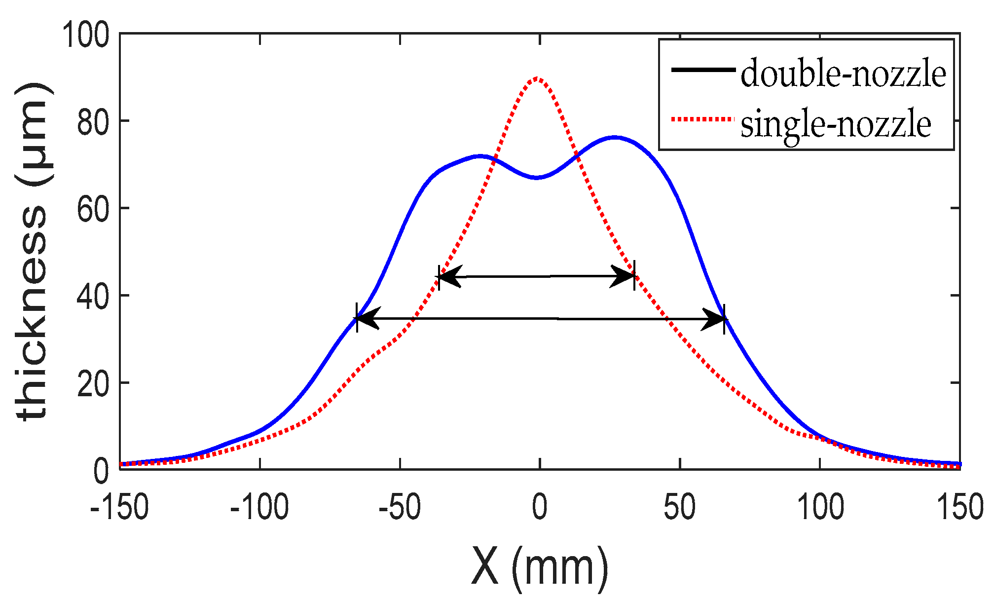
The same boundary parameters were used for double-nozzle and single-nozzle air spray guns. The parameters are shown in Table 1. The single-nozzle spray gun has a mass flow rate of 1.5 × 10⁻³ kg/s and the double-nozzle spray gun has a mass flow rate of 0.75 × 10⁻³ kg/s for each paint hole. The double-nozzle spray gun, with structural parameters of L = 30 mm and θ = 10°, was selected for simulation. Figure 16 shows the coating film thickness contours. The maximum visible thickness was set to 0.1 mm. Figure 17 displays the comparison of coating thickness profiles along the x-axis between double-nozzle and single-nozzle air spray guns. From Figure 16 and Figure 17, it can be concluded that the double-nozzle air spray gun can obtain a more uniform coating film, which can avoid overspray. It is assumed that half of the maximum coating thickness is the effective spray thickness. The effective spraying widths of double-nozzle and single-nozzle spray guns are L1 = 130 mm and L2 = 70 mm, respectively. The effective spraying width of the double-nozzle air spray gun is increased by 85.7% compared with the single-nozzle air spray gun, improving the spraying efficiency.

4. Conclusions

In this paper, a new double-nozzle air spray gun structure was designed based on the Coanda effect of double jets. The interference spray flow field was numerically studied with the help of the ANSYS-Fluent CFD software. Negative pressure was generated in the region between the two jets due to the entrainment of the jets, which made the jets attract each other. Finally, the two jets combined into one jet. The interference spray flow field has significant influence on the droplet trajectory and coating thickness distribution.
The effects of L (the distance between the centers of two paint holes) and θ (the angle between the axes of the two paint holes) on the interference flow field are similar to each other. The two jets combine into one jet near the y = 35 mm cross-section. The larger L and θ are, the greater the distance from the position where the two jets begin to combine into one jet towards the spray gun; the smaller the absolute value of the velocity in the region near the central axis is, the greater the absolute value of the velocity in the region far away from the central axis and the larger the extension distance of the velocity field along the x-axis.
The effects of L and θ on the coating thickness distribution are similar to each other. The smaller L and θ are, the stronger the interference effect, and the more concentrated the paint is in the central area of the target surface, the easier it is to cause overspray. If L and θ are too small, the interference effect will become too strong and the shape of the coating film will become a rhombus. If L and θ are too large, the interference effect will become too weak and the shape of the coating film will become a concave, with more paint in both side regions and less paint in the central region, which will also easily cause an uneven coating film. From the simulation results, it can be seen that a more uniform coating film can be obtained when L = 30 mm and θ = 10°. The effective coating width of the double-nozzle air spray gun is increased by 85.7% compared with the single-nozzle air spray gun, which improves the spraying efficiency.

Author Contributions

Conceptualization, Y.-A.W. and X.-P.X.; investigation, Y.-A.W.; methodology, Y.-A.W.; Project Administration, X.-H.L. and X.-P.X.; software, Y.-A.W. and X.-H.L.; Writing—Original Draft, Y.-A.W.; Writing—Review and Editing, Y.-A.W. and X.-H.L. All authors have read and agreed to the published version of the manuscript.

Funding

This research received no external funding.

Conflicts of Interest

The authors declare no conflict of interest.

References

  1. Andulkar, M.V.; Chiddarwar, S.S.; Marathe, A.S. Novel integrated offline trajectory generation approach for robot assisted spray painting operation. J. Manuf. Syst. 2015, 37, 201–216. [Google Scholar] [CrossRef]
  2. Chen, H.P.; Xi, N. Automated tool trajectory planning of industrial robots for painting composite surfaces. Int. J. Adv. Manuf. Technol. 2008, 35, 680–696. [Google Scholar] [CrossRef]
  3. Chen, W.Z.; Chen, Y.; Li, B.; Zhang, W.M.; Chen, K. Design of redundant robot painting system for long non-regular duct. Ind. Robot 2016, 43, 58–64. [Google Scholar] [CrossRef]
  4. Chen, W.Z.; Chen, Y.; Zhang, W.M.; He, S.W.; Li, B.; Jiang, J.Z. Paint thickness simulation for robotic painting of curved surfaces based on Euler-Euler approach. J. Braz. Soc. Mech. Sci. Eng. 2019, 41, 9. [Google Scholar] [CrossRef]
  5. Chen, H.P.; Xi, N. Automated robot tool trajectory connection for spray forming process. J. Manuf. Sci. Eng. Trans. ASME 2012, 134, 9. [Google Scholar] [CrossRef]
  6. Guan, L.W.; Chen, L. Trajectory planning method based on transitional segment optimization of spray painting robot on complex-free surface. Ind. Robot 2019, 46, 31–43. [Google Scholar] [CrossRef]
  7. Park, K.; Jeon, D. Optimization of Tool Path Pitch of Spray Painting Robots for Automotive Painting Quality. Int. J. Control Autom. Syst. 2018, 16, 2832–2838. [Google Scholar] [CrossRef]
  8. Suk-Hwan, S.; In-Kee, W.; Sung-Kee, N. Automatic trajectory planning system (ATPS) for spray painting robots. J. Manuf. Syst. 1991, 10, 396–406. [Google Scholar] [CrossRef]
  9. Zhang, Y.J.; Li, W.B.; Zhang, C.; Liao, H.L.; Zhang, Y.C.; Deng, S.H. A spherical surface coating thickness model for a robotized thermal spray system. Robot. Comput. Integr. Manuf. 2019, 59, 297–304. [Google Scholar] [CrossRef]
  10. Arikan, M.A.S.; Balkan, T. Process simulation and paint thickness measurement for robotic spray painting. CIRP Ann. Manuf. Technol. 2001, 50, 291–294. [Google Scholar] [CrossRef]
  11. Chen, H.P.; Xi, N.; Sheng, W.H.; Chen, M.F. General framework of optimal tool trajectory planning for free-form surfaces in surface manufacturing. J. Manuf. Sci. Eng. Trans. ASME 2005, 127, 49–59. [Google Scholar] [CrossRef]
  12. Feng, C.; Sun, Z.-Q. Models of spray gun and simulation in robotics spray painting. Robot 2003, 25, 353–358. [Google Scholar]
  13. Klein, A. CAD-based off-line programming of painting robots. Robotica 1987, 5, 267–271. [Google Scholar] [CrossRef]
  14. Antonio, J.K. Optimal trajectory planning for spray coating. In Proceedings of the 1994 IEEE International Conference on Robotics and Automation (Cat. No.94CH3375-3), San Diego, CA, USA, 8–13 May 1994; Volume 2573, pp. 2570–2577. [Google Scholar] [CrossRef] [Green Version]
  15. Freund, E.; Rokossa, D.; Rossmann, J. Process-oriented approach to an efficient off-line programming of industrial robots. In Proceedings of the 24th Annual Conference of the IEEE Industrial Electronics Society, IECON ‘98, Aachen, Germany, 31 August–4 September 1998; IEEE: New York, NY, USA, 1998; Volume 1–4, pp. 208–213. [Google Scholar]
  16. Arikan, M.A.S.; Balkan, T. Modeling of paint flow rate flux for elliptical paint sprays by using experimental paint thickness distributions. Ind. Robot 2006, 33, 60–66. [Google Scholar] [CrossRef]
  17. Zhang, Y.; Huang, Y.; Gao, F.; Wang, W. New model for air spray gun of robotic spray-painting. Chin. J. Mech. Eng. 2006, 42, 226–233. [Google Scholar] [CrossRef]
  18. Chen, Y.; Chen, W.Z.; Li, B.; Zhang, G.; Zhang, W.M. Paint thickness simulation for painting robot trajectory planning: A review. Ind. Robot 2017, 44, 629–638. [Google Scholar] [CrossRef]
  19. Xie, X.P.; Wang, Y.N. Research on distribution properties of coating film thickness from air spraying gun-based on numerical simulation. Coatings 2019, 9, 721. [Google Scholar] [CrossRef] [Green Version]
  20. Li, W.T.; Qian, L.J.; Song, S.B.; Zhong, X.K. Numerical study on the influence of shaping air holes on atomization performance in pneumatic atomizers. Coatings 2019, 9, 410. [Google Scholar] [CrossRef] [Green Version]
  21. Osman, H.; Adamiak, K.; Castle, G.S.P.; Fan, H.T.; Simmer, J. ASME Comparison between the Numerical and Experimental Deposition Patterns for an Electrostatic Rotary Bell Sprayer; American Society of Mechanical Engineers: New York, NY, USA, 2016. [Google Scholar]
  22. Ye, Q.; Shen, B.; Tiedje, O.; Bauernhansl, T.; Domnick, J. Numerical and experimental study of spray coating using air-assisted high-pressure atomizers. Atom. Sprays 2015, 25, 643–656. [Google Scholar] [CrossRef] [Green Version]
  23. Ye, Q.Y.; Pulli, K. Numerical and experimental investigation on the spray coating process using a pneumatic atomizer: Influences of operating conditions and target geometries. Coatings 2017, 7, 13. [Google Scholar] [CrossRef] [Green Version]
  24. Domnick, J.; Scheibe, A.; Ye, Q.Y. The simulation of the electrostatic spray painting process with high-speed rotary bell atomizers. Part I: Direct charging. Part. Part. Syst. Charact. 2005, 22, 141–150. [Google Scholar] [CrossRef]
  25. Domnick, J.; Scheibe, A.; Ye, Q.Y. The simulation of electrostatic spray painting process with high-speed rotary bell atomizers. Part II: External charging. Part. Part. Syst. Charact. 2007, 23, 408–416. [Google Scholar] [CrossRef]
  26. Ye, Q.; Domnick, J. Analysis of droplet impingement of different atomizers used in spray coating processes. J. Coat. Technol. Res. 2017, 14, 467–476. [Google Scholar] [CrossRef]
  27. Fogliati, M.; Fontana, D.; Garbero, M.; Vanni, M.; Baldi, G.; Donde, R. CFD simulation of paint deposition in an air spray process. JCT Res. 2006, 3, 117–125. [Google Scholar] [CrossRef]
  28. Chen, Y.; He, S.W.; Zhang, G.; Chen, W.Z.; Jiang, J.Z. Numerical Simulation of Air Spray using the Eulerian multiphase model. In Proceedings of the 2016 4th International Conference on Machinery, Materials and Computing Technology, Hangzhou, China, 23–24 January 2016; Zhu, J., Yao, G., Eds.; Atlantis Press: Paris, France, 2016; Volume 60, pp. 1229–1232. [Google Scholar]
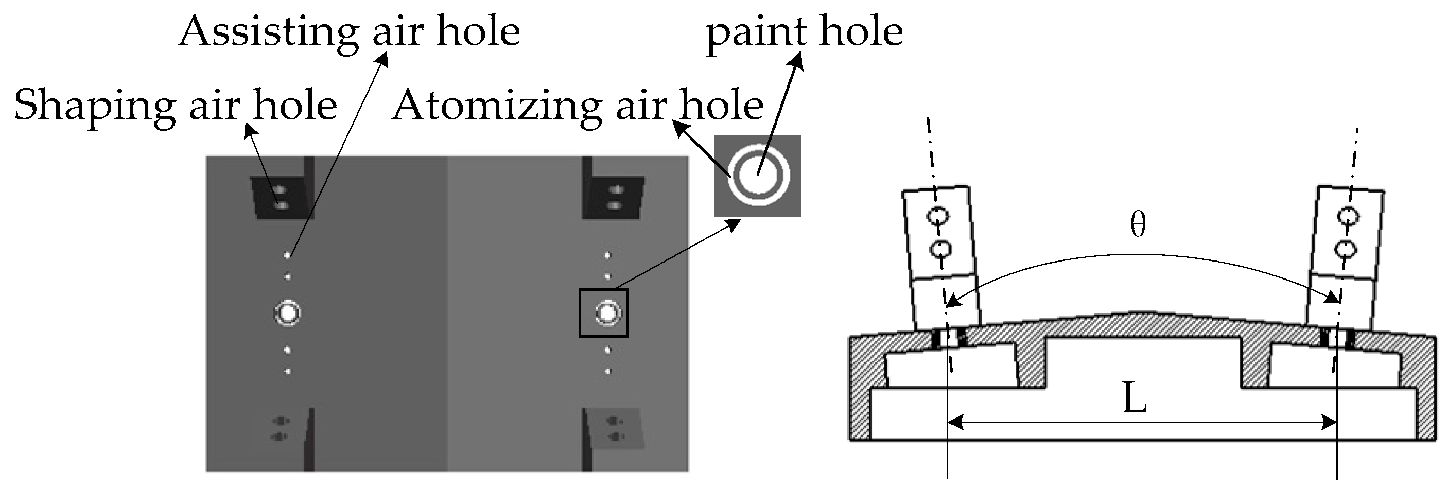
Figure 1. Geometry of the air cap of the double-nozzle air spray gun.
Coatings 10 00475 g001
Figure 2. Definition of coordinate system.
Coatings 10 00475 g002
Figure 3. Computational domain and grid.
Coatings 10 00475 g003
Figure 4. Comparison of coating thickness distribution along the x-axis for five kinds of grids, with 0.27, 0.58, 1.26, 1.85, and 2.16 million cells.
Coatings 10 00475 g004
Figure 5. Velocity contours at section z = 0 for different L when θ = 10°: (a) L = 20 mm; (b) L = 30 mm; (c) L = 40 mm; (d) L = 50 mm.
Coatings 10 00475 g005
Figure 6. Velocity profiles along the y-axis direction for each cross-section: (a) y = 15 mm; (b) y = 25 mm; (c) y = 35 mm; (d) y = 50 mm; (e) y = 100 mm; (f) y = 170 mm.
Coatings 10 00475 g006
Figure 7. Velocity profiles along the central axis when θ = 10°.
Coatings 10 00475 g007
Figure 8. Velocity contours at section z = 0 for different θ values when L = 30 mm: (a) θ = 0°; (b) θ = 5°; (c) θ = 10°; (d) θ = 15°.
Coatings 10 00475 g008
Figure 9. Velocity profiles along the y-axis direction for each cross-section when L = 30 mm: (a) y = 15 mm; (b) y = 25 mm; (c) y = 35 mm; (d) y = 50 mm; (e) y = 100 mm; (f) y = 170 mm.
Coatings 10 00475 g009
Figure 10. Velocity profiles along the y-axis when L = 30 mm.
Coatings 10 00475 g010
Figure 11. Coating film thickness contours when L = 20 mm: (a) θ = 0°; (b) θ = 5°; (c) θ = 10°; (d) θ = 15°.
Coatings 10 00475 g011
Figure 12. Coating film thickness contours when L = 30 mm: (a) θ = 0°; (b) θ = 5°; (c) θ = 10°; (d) θ = 15°.
Coatings 10 00475 g012
Figure 13. Coating film thickness contours when L = 40 mm: (a) θ = 0°; (b) θ = 5°; (c) θ = 10°; (d) θ = 15°.
Coatings 10 00475 g013
Figure 14. Coating thickness profiles along the x-axis for different θ values when L = 30 mm.
Coatings 10 00475 g014
Figure 15. Coating thickness profiles along the x-axis for different L values when θ = 10°.
Coatings 10 00475 g015
Figure 16. Coating film thickness contours: (a) double-nozzle air spray gun; (b) single-nozzle air spray gun.
Coatings 10 00475 g016
Figure 17. Comparison of coating thickness profiles along the x-axis between double-nozzle and single-nozzle air spray guns.
Coatings 10 00475 g017
Table 1. Parameters for numerical simulation.
Atomizing Air PressureShaping Air PressureAssisting Air PressureLiquid Flow Rate
0.15 MPa0.07 MPa0.15 MPa0.0015 kg/s
Table 2. Properties of the paint and air.
Materials Density (kg/m3)Surface Tension (mN/m)Viscosity (Pa·s)
Paint120071.90.065
Air1.291.8 × 10−5
Table 3. Values of L and θ.
VariablesValues
L20, 30, 40, 50 mm
θ0°, 5°, 10°, 15°