Optical and Chromaticity Properties of Metal-Dielectric Composite-Based Multilayer Thin-Film Structures Prepared by RF Magnetron Sputtering

 ,
,  , ,
, ,  and
and
Abstract
1. Introduction
2. Growth and Characteristics of Thin Metallic Films, Metal-Dielectric Composites, and Multilayer Structures
2.1. Optical and Chromaticity Properties of Single-Layer Ultrathin Metal Layers
2.2. Optical and Chromaticity Properties of Single-Layer Ultrathin Metal-Dielectric Composites
2.3. Metal Layer-Based DMD Type Multilayer Structures
2.4. MDC Layer-Based DMD-Type Multilayer Structures
3. Conclusions
Supplementary Materials
Author Contributions
Funding
Conflicts of Interest
References
- Chu, S.; Majumdar, A. Opportunities and challenges for a sustainable energy future. Nature 2012, 488, 294. [Google Scholar] [CrossRef] [PubMed]
- International Energy Outlook 2010. A Report by the Office of Integrated Analysis and Forecasting. U.S. Energy Information Administration, U.S. Department of Energy (July 2010). Available online: http://www.eia.doe.gov/oiaf/ieo/pdf/0484(2010).pdf (accessed on 9 March 2020).
- Gläser, H.J. Large Area Glass Coating; Von Ardenne Anlagentechnik GmbH: Dresden, Germany, 2000. [Google Scholar]
- Dalapati, G.K.; Kushwaha, A.K.; Sharma, M.; Suresh, V.; Shannigrahi, S.; Zhuk, S.; Masudy-Panah, S. Transparent heat regulating (THR) materials and coatings for energy saving window applications: Impact of materials design, micro-structural, and interface quality on the THR performance. Prog. Mater. Sci. 2018, 95, 42–131. [Google Scholar] [CrossRef]
- Vasiliev, M.; Nur-E-Alam, M.; Alameh, K. Recent developments in solar energy-harvesting technologies for building integration and distributed energy generation. Energies 2019, 12, 1080. [Google Scholar] [CrossRef]
- Granqvist, C.G. Oxide-based chromogenic coatings and devices for energy efficient fenestration: Brief survey and update on thermochromics and electrochromics. J. Vac. Sci. Technol. B 2014, 32, 060801. [Google Scholar] [CrossRef]
- Peres, L.; Bou, A.; Barakel, D.; Torchio, P. ZnS/Ag/TiO2 multilayer electrodes with broadband transparency for thin film solar cells. RSC Adv. 2016, 6, 61057–61063. [Google Scholar] [CrossRef]
- Kim, J.-H.; Kim, D.-H.; Kim, S.-K.; Bae, D.; Yoo, Y.-Z.; Seong, T.-Y. Control of refractive index by annealing to achieve high figure of merit for TiO2/Ag/TiO2 multilayer films. Ceram. Int. 2016, 42, 14071–14076. [Google Scholar] [CrossRef]
- Pracchia, J.; Simon, J. Transparent heat mirrors: Influence of the materials on the optical characteristics. Appl. Opt. 1981, 20, 251–258. [Google Scholar] [CrossRef]
- Leftheriotis, G.; Yianoulis, P.; Patrikios, D. Deposition and optical properties of optimised ZnS/Ag/ZnS thin films for energy saving applications. Thin Solid Film. 1997, 306, 92–99. [Google Scholar] [CrossRef]
- Kulczyk-Malecka, J.; Kelly, P.; West, G.; Clarke, G.; Ridealgh, J.; Almtoft, K.; Greer, A.; Barber, Z. Investigation of silver diffusion in TiO2/Ag/TiO2 coatings. Acta Mater. 2014, 66, 396–404. [Google Scholar] [CrossRef]
- Wang, Z.; Cai, X.; Chen, Q.; Chu, P.K. Effects of Ti transition layer on stability of silver/titanium dioxide multilayered structure. Thin Solid Film. 2007, 515, 3146–3150. [Google Scholar] [CrossRef]
- Wang, L.; Shen, Z.; Du, G.; Wang, P.; Wang, P. The thermal stability of silver-based high reflectance coatings. Thin Solid Film. 2016, 616, 122–125. [Google Scholar] [CrossRef]
- Mosquera, A.A.; Albella, J.M.; Navarro, V.; Bhattacharyya, D.; Endrino, J.L. Effect of silver on the phase transition and wettability of titanium oxide films. Sci. Rep. 2016, 6, 32171. [Google Scholar] [CrossRef] [PubMed]
- Mohelnikova, J. Materials for reflective coatings of window glass applications. Constr. Build. Mater. 2009, 23, 1993–1998. [Google Scholar] [CrossRef]
- Carton, O.; Ghaymouni, J.; Lejeune, M.; Zeinert, A. Optical characterization of porous sputtered silver thin films. J. Spectrosc. 2013, 1, 307824. [Google Scholar] [CrossRef]
- Chen, W.; Thoreson, M.D.; Kildishev, A.V.; Shalaev, V.M. Ultra-Thin Ultra-Smooth and Low-Loss Silver and Silver-Silica Composite Films for Superlensing Applications; CLEO: QELS_Fundamental Science: San Jose, CA, USA, 2010; Available online: https://engineering.purdue.edu/~shalaev/Publication_list_files/QThE4.pdf (accessed on 26 December 2010).
- Anders, A.; Byon, E.; Kim, D.; Fukuda, K.; Lim, S.N. Smoothing of ultrathin silver films by transition metal seeding. Solid State Commun. 2006, 140, 225–229. [Google Scholar] [CrossRef]
- Bulir, J.; Novotny, M.; Lynnykova, A.; Lancok, J. Preparation of nanostructured ultrathin silver layer. J. Nanophotonics 2011, 5, 051511. [Google Scholar] [CrossRef]
- Jiang, X.; Chen, S.; Mao, C. Synthesis of Ag/SiO2 nanocomposite material by adsorption phase nanoreactor technique. Colloids Surf. A Physicochem. Eng. Asp. 2008, 320, 104–110. [Google Scholar] [CrossRef]
- Yu, B.; Leung, K.M.; Guo, Q.; Lau, W.M.; Yang, J. Synthesis of Ag–TiO2 composite nano thin film for antimicrobial application. Nanotechnology 2011, 22, 115603. [Google Scholar] [CrossRef]
- Cummings, K.D.; Garland, J.C.; Tanner, D.B. Optical properties of a small-particle composite. Phys. Rev. B 1984, 30, 4170–4182. [Google Scholar] [CrossRef]
- Zhao, Y.L.; Xu, X.; Ming, H. Ag-MgF2 composite films deposited by RF magnetron sputtering. J. Funct. Mater. 2007, 38, 386–388. [Google Scholar]
- Nur-E-Alam, M.; Lonsdale, W.; Vasiliev, M.; Alameh, K. Application specific oxide-based and metal-dielectric thin-film materials prepared by radio frequency magnetron sputtering. Materials 2019, 12, 3448. [Google Scholar] [CrossRef] [PubMed]
- Dalapati, D.K.; Sharma, M. Energy Saving Coating Materials, Ch.4; Elsevier: Amsterdam, The Netherlands; Thomson Digital: Noida, India, 2020; in press. [Google Scholar]
- Politano, G.G.; Cazzanelli, E.; Versace, C.; Castriota, M.; Desiderio, G.; Davoli, M.; Vena, C.; Bartolino, R. Micro-raman investigation of Ag/graphene oxide/Au sandwich structure. Mater. Res. Express 2019, 6, 075605. [Google Scholar] [CrossRef]
- Politano, G.G.; Cazzanelli, E.; Versace, C.; Vena, C.; De Santo, M.P.; Castriota, M.; Ciuchi, F.; Bartolino, R. Graphene oxide on magnetron sputtered silver thin films for SERS and metamaterial applications. Appl. Surf. Sci. 2018, 427, 927–933. [Google Scholar] [CrossRef]
- Sarangan, A. Design of metal-dielectric resonant-cavity thin-film structures using the effective reflectance index method. J. Opt. Soc. Am. B 2018, 35, 2294–2301. [Google Scholar] [CrossRef]
- Chen, L.; Chen, N.; Li, Y.; Li, W.; Zhou, X.; Wang, Z.; Zhao, Y.; Bu, Y. Metal-dielectric pure red to gold special effect coatings for security and decorative applications. Surf. Coat. Technol. 2019, 363, 18–24. [Google Scholar] [CrossRef]
- Schueler, A.; Roecker, C.; Scartezzini, J.-L.; Boudaden, J.; Videnovic, I.; Ho, R.-C.; Oelhafen, P. On the feasibility of colored glazed thermal solar collectors based on thin film interference filters. Sol. Energy Mater. Sol. Cells 2004, 84, 241–254. [Google Scholar] [CrossRef]
- Orel, B.; Spreizer, H.; Vuk, A.Š.; Fir, M.; Merlini, D.; Vodlan, M.; Köhl, M. Selective paint coatings for coloured solar absorbers: Polyurethane thickness insensitive spectrally selective (TISS) paints (Part II). Sol. Energy Mater. Sol. Cells 2007, 91, 108–119. [Google Scholar] [CrossRef]
- Bu, Y.; Guo, R.; Li, Y.; Meng, Z.; Chen, N. All-dielectric metameric filters for optically variable devices. Chin. Opt. Lett. 2014, 12. [Google Scholar] [CrossRef]
- Kalfagiannis, N.; Logothetidis, S. Color dependency on optical and electrical properties of TiNx thin films. Rev. Adv. Mater. Sci. 2007, 15, 167–172. [Google Scholar]
- Rashid, H.G.; Mishjil, K.A.; Habubi, N.F. Color space chromaticity diagram: Estimation of Co impurity ratios in SnO2 thin films. Mater. Sci. 2013, 9, 187–191. [Google Scholar]
- Ellenbogen, T.; Seo, K.; Crozier, K.B. Chromatic plasmonic polarizers for active visible color filtering and polarimetry. Nano Lett. 2012, 12, 1026–1031. [Google Scholar] [CrossRef] [PubMed]
- Diest, K.; Dionne, J.A.; Spain, M.; Atwater, H.A. Tunable color filters based on metal-insulator-metal resonators. Nano Lett. 2009, 9, 2579–2583. [Google Scholar] [CrossRef]
- Xu, T.; Shi, H.; Wu, Y.K.; Kaplan, A.F.; Ok, J.G.; Guo, L.J. Structural colors: From plasmonic to carbon nanostructures. Small 2011, 7, 3128–3136. [Google Scholar] [CrossRef] [PubMed]
- Song, M.; Wang, D.; Peana, S.; Choudhury, S.; Nyga, P.; Kudyshev, Z.A.; Yu, H.; Boltasseva, A.; Shalaev, V.M.; Kildishev, A.V. Colors with plasmonic nanostructures: A full-spectrum review. Appl. Phys. Rev. 2019, 6, 041308. [Google Scholar] [CrossRef]
- Song, H.S.; Lee, G.J.; Yoo, D.E.; Kim, Y.J.; Yoo, Y.J.; Lee, D.W.; Siva, V.; Kang, I.S.; Song, Y.M. Reflective color filter with precise control of the color coordinate achieved by stacking silicon nanowire arrays onto ultrathin optical coatings. Sci. Rep. 2019, 9, 93350. [Google Scholar] [CrossRef]
- Dalapati, G.K.; Masudy-Panah, S.; Chua, S.T.; Sharma, M.; Wong, T.I.; Tan, H.R.; Chi, D. Color tunable low cost transparent heat reflector using copper and titanium oxide for energy saving application. Sci. Rep. 2016, 6, 20182. [Google Scholar] [CrossRef]
- Devaraj, V.; Lee, J.; Baek, J.; Lee, D. Fabrication of ultra-smooth 10 nm silver films without wetting layer. Appl. Sci. Converg. Technol. 2016, 25, 32–35. [Google Scholar] [CrossRef]
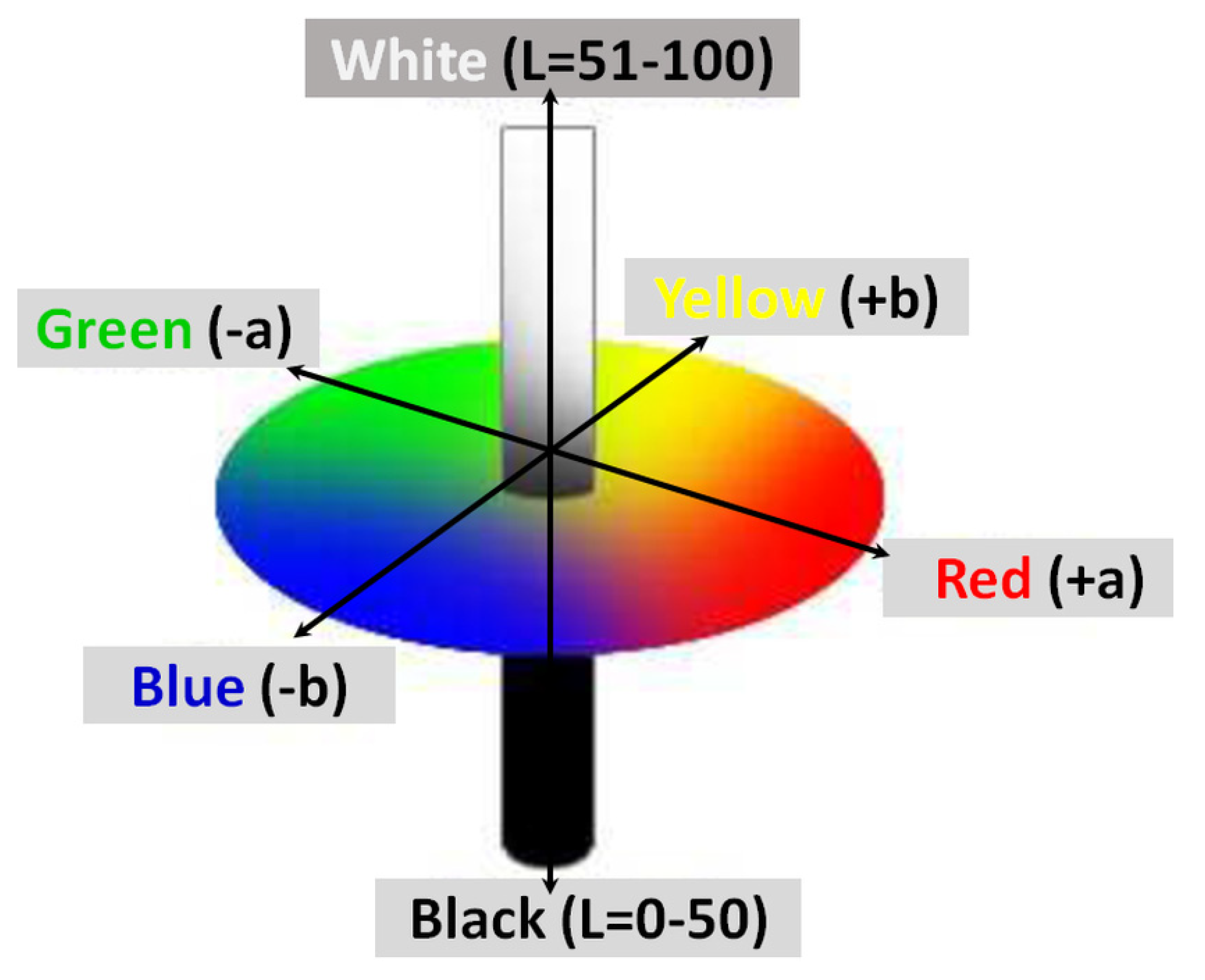
- Robartson, A.R. The CIE 1976 color-difference formulae. Color. Res. 1977, 2, 7–11. [Google Scholar] [CrossRef]
- Available online: https://support.hunterlab.com›en-us›article_attachments (accessed on 10 January 2020).
- Lovetskiy, K.P.; Sevastianov, L.A.; Nikolaev, N.E. Numerical modeling of color perception of optical radiation. Math. Model. Geom. 2018, 6, 21–36. [Google Scholar] [CrossRef]
- Available online: https://www.pce-italia.it/html/dati-tecnici-1/misuratore-di-colore-cta.htm (accessed on 12 January 2020).
- Available online: https://www.pce-instruments.com/turkish/oel_uem-teknolojisi/oel_uem-cihazlarae_/spektrometre-spektrofotometre-kat_159226.htm (accessed on 13 January 2020).
- Abass, K.H. Fe2O3 thin films prepared by spray pyrolysis technique and study the annealing on its optical properties. Int. Lett. Chem. Phys. Astron. 2015, 45, 24–31. [Google Scholar] [CrossRef]
- Cho, S. Optical and electrical properties of CuO thin films deposited at several growth temperatures by reactive RF magnetron sputtering. Met. Mater. Int. 2013, 19, 1327–1331. [Google Scholar] [CrossRef]
- Vasiliev, M.; Nur-E-Alam, M.; Alameh, K. Highly stable thin-film multilayers for thermal regulation and energy savings in smart cities. In Proceedings of the 16th IEEE International Conference on Smart Cities: Improving Quality of Life Using ICT, IoT & AI, Charlotte, NC, USA, 6–9 October 2019. [Google Scholar]


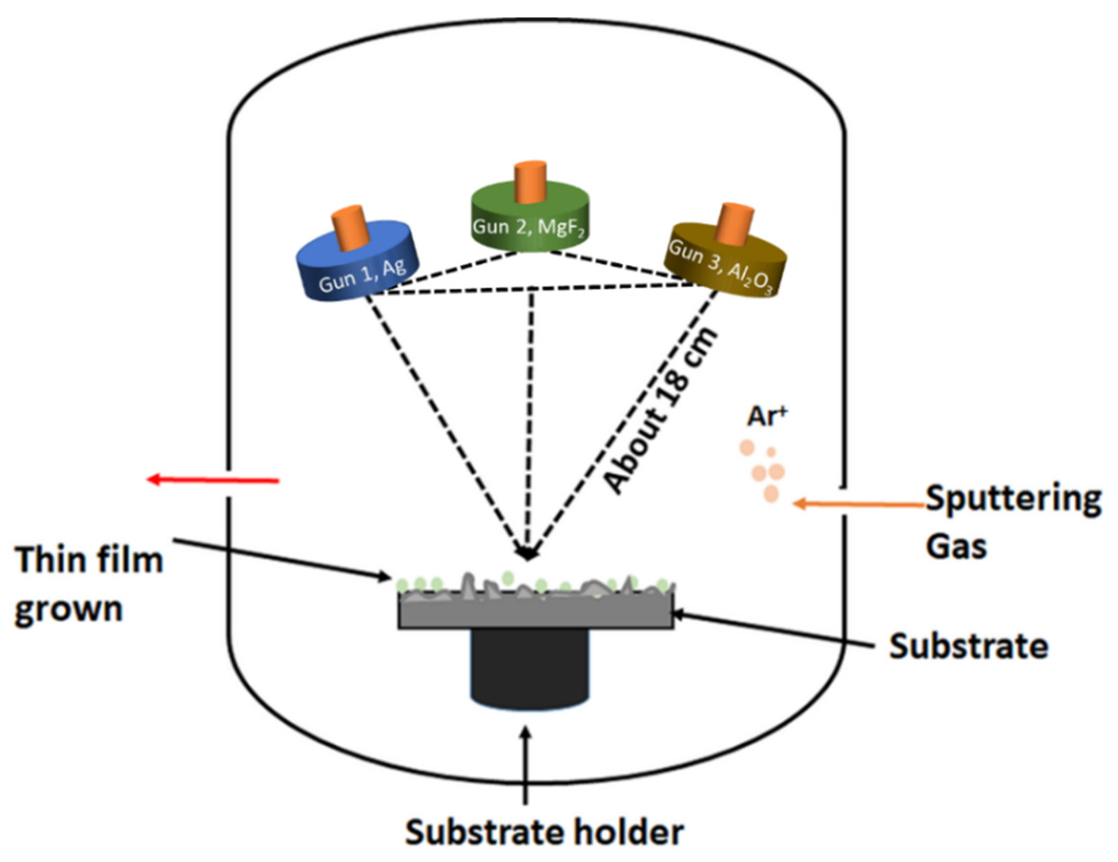
| Process Parameters | Layer Structure (Ag (Single) Layer) | Layer Structure (Metal-Dielectric Composite (Single) Layer) | Layer Structure (DMD Type Multilayers) |
|---|---|---|---|
| Sputtering targets (7.62 cm diameter) | Ag | Ag and MgF2 | Ag, MgF2, and Al2O3 |
| Radio frequency (RF) power | 64 W | Ag (30–64 W), MgF2 (83 W) | Ag (64 W), MgF2 (83 W), and Al2O3 (199 W) |
| Base pressure (Torr) | <3 × 10⁻⁶–5 × 10⁻⁶ | <3 × 10⁻⁶–5 × 10⁻⁶ | <3 × 10⁻⁶–5 × 10⁻⁶ |
| Process gas | Ar | Ar | Ar |
| Process pressure | 2–3 mTorr | 2–3 mTorr | 2–3 mTorr |
| Target-to-substrate distance (cm) | ~18 | ~18 | ~18 |
| Substrate stage rotation rate (rpm) | 15–16 | 15–16 | 15–16 |
| Substrate temperature (°C) | Room temperature | Room temperature | Room temperature |
| Ag Layer Thickness | Simulated Hunter L, a, b (Ra) Values | Measured Hunter L, a, b (Ra) Values | |||||
|---|---|---|---|---|---|---|---|
| Experimental (nm) | Model Fitted (nm) | L | a | b | L | a | b |
| 10.0 | 9.5 | 54.16 | 4.54 | 15.37 | 52.7 | 2.67 | 8.62 |
| 12.5 | 12.6 | 66.03 | 4.57 | 18.42 | 64.37 | 2.58 | 12 |
| 15.6 | 15.6 | 70.70 | 4.39 | 19.17 | 68.80 | 2.22 | 12.26 |
| 17.0 | 18.2 | 75.78 | 4.08 | 19.61 | 74.94 | 1.68 | 11.95 |
| 21.0 | 22.0 | 81.54 | 3.69 | 19.55 | 80.54 | 1.05 | 11.00 |
| Sample Type | Layer Information | Simulated Hunter L, a, b (Ra) Values | Measured Hunter L, a, b (Ra) Values | |||||
|---|---|---|---|---|---|---|---|---|
| Deposition Run (s) | Estimated Layer Thickness (nm) | L | a | b | L | a | b | |
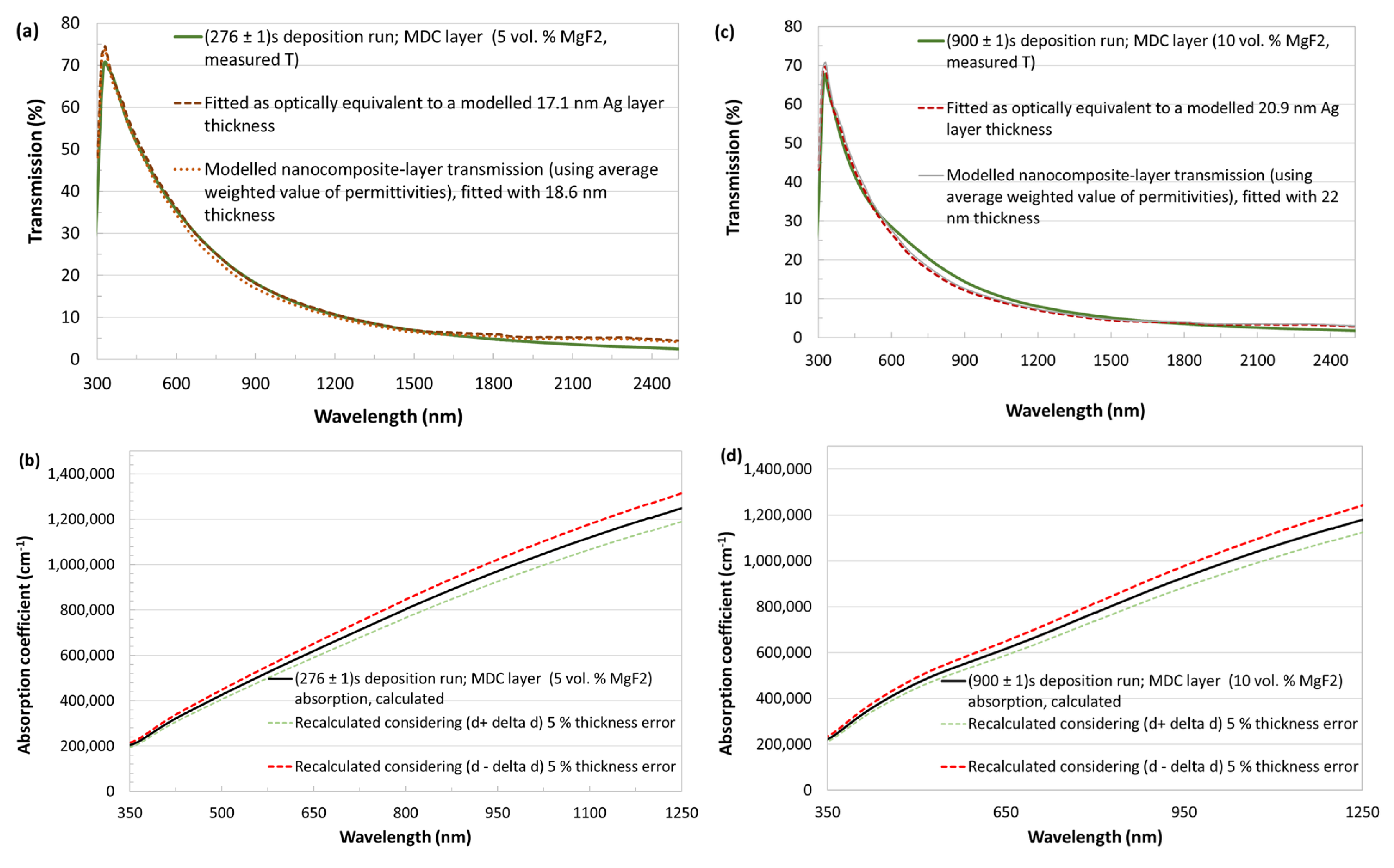
| MDC layers (Ag + 5 vol.% MgF2) | 240 ± 1 | 14.3 ± 0.1 | 65.99 | 4.62 | 18.52 | 62.56 | 1.34 | 8.37 |
| 276 ± 1 | 18.6 ± 0.1 | 74.85 | 4.18 | 19.70 | 70.50 | 2.17 | 11.19 | |
| 300 ± 1 | 19.8 ± 0.1 | 76.86 | 4.03 | 19.79 | 71.04 | 1.38 | 9.49 | |
| 360 ± 1 | 22.6 ± 0.1 | 80.88 | 3.71 | 19.74 | 79.41 | 1.29 | 11.16 | |
| 420 ± 1 | 26 ± 0.1 | 84.73 | 3.38 | 19.34 | 83.00 | 0.84 | 10.34 | |
| 480 ± 1 | 30 ± 0.1 | 88.13 | 3.10 | 18.63 | 86.67 | 0.43 | 9.09 | |
| MDC layer (Ag + 10 vol.% MgF2) | 900 ± 1 | 22 ± 0.1 | 78.50 | 3.87 | 19.84 | 70.80 | 1.41 | 8.94 |
| Sample Type | Simulated Hunter L, a, b (Ra) Values | Measured Hunter L, a, b (Ra) Values | ||||
|---|---|---|---|---|---|---|
| L | a | b | L | a | b | |
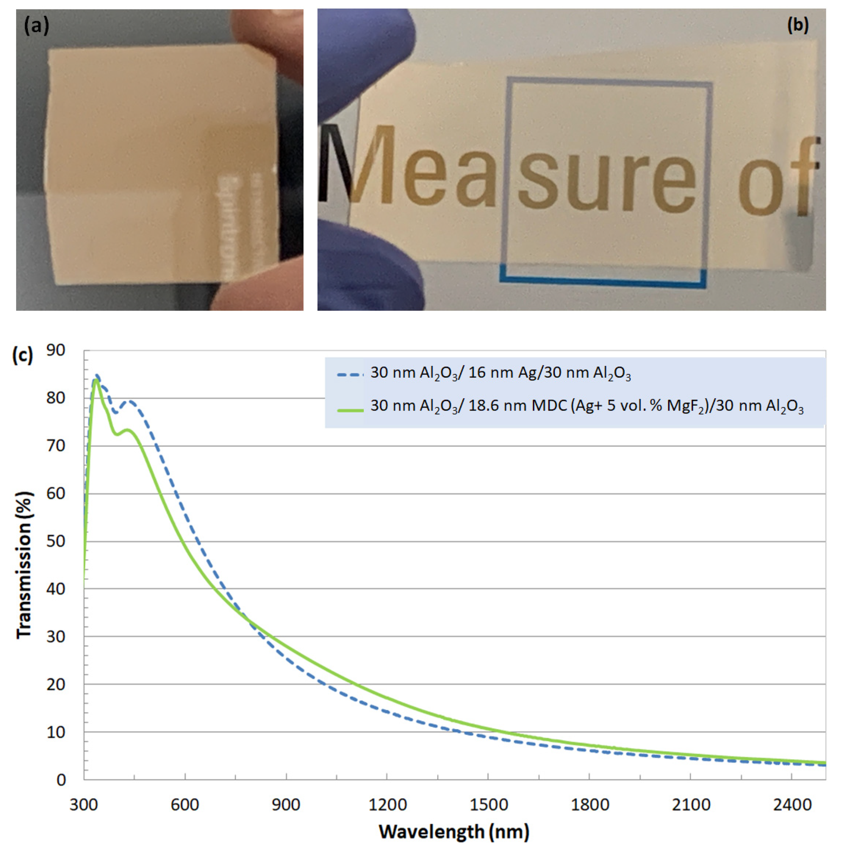
| 30 nm Al2O3/16 nm Ag/30 nm Al2O3 | 55.21 | 7.77 | 25.31 | 53.12 | 6.56 | 21.07 |
| 30 nm Al2O3/11.8 nm MDC/30 nm Al2O3 | 39.64 | 8.58 | 19.12 | 39.28 | 6.40 | 15.03 |
| 30 nm Al2O3/18.6 nm MDC/30 nm Al2O3 | 59.85 | 7.29 | 26.52 | 55.80 | 4.80 | 20.29 |
| 30 nm Al2O3/19.8 MDC/30 nm Al2O3 | 62.77 | 6.86 | 27.09 | 60.43 | 4.85 | 21.86 |
© 2020 by the authors. Licensee MDPI, Basel, Switzerland. This article is an open access article distributed under the terms and conditions of the Creative Commons Attribution (CC BY) license (http://creativecommons.org/licenses/by/4.0/).
Share and Cite
Nur-E-Alam, M.; Rahman, M.M.; Basher, M.K.; Vasiliev, M.; Alameh, K. Optical and Chromaticity Properties of Metal-Dielectric Composite-Based Multilayer Thin-Film Structures Prepared by RF Magnetron Sputtering. Coatings 2020, 10, 251. https://doi.org/10.3390/coatings10030251
Nur-E-Alam M, Rahman MM, Basher MK, Vasiliev M, Alameh K. Optical and Chromaticity Properties of Metal-Dielectric Composite-Based Multilayer Thin-Film Structures Prepared by RF Magnetron Sputtering. Coatings. 2020; 10(3):251. https://doi.org/10.3390/coatings10030251
Chicago/Turabian StyleNur-E-Alam, Mohammad, Md Momtazur Rahman, Mohammad Khairul Basher, Mikhail Vasiliev, and Kamal Alameh. 2020. "Optical and Chromaticity Properties of Metal-Dielectric Composite-Based Multilayer Thin-Film Structures Prepared by RF Magnetron Sputtering" Coatings 10, no. 3: 251. https://doi.org/10.3390/coatings10030251
APA StyleNur-E-Alam, M., Rahman, M. M., Basher, M. K., Vasiliev, M., & Alameh, K. (2020). Optical and Chromaticity Properties of Metal-Dielectric Composite-Based Multilayer Thin-Film Structures Prepared by RF Magnetron Sputtering. Coatings, 10(3), 251. https://doi.org/10.3390/coatings10030251