Article

Preparation of Plasmonic Au-TiO2 Thin Films on a Transparent Polymer Substrate

Centro de Física, Universidade do Minho, Campus de Gualtar, 4710-057 Braga, Portugal
*
Author to whom correspondence should be addressed.
Coatings 2020, 10(3), 227; https://doi.org/10.3390/coatings10030227
Submission received: 29 January 2020 / Revised: 20 February 2020 / Accepted: 27 February 2020 / Published: 2 March 2020

Abstract

:
In this work, plasmonic thin films composed of Au nanoparticles embedded in a TiO2 matrix were prepared in a transparent polymer substrate of poly(dimethylsiloxane) (PDMS). The thin films were deposited by reactive DC magnetron sputtering, and then subjected to heat treatment up to 150 °C in order to promote the growth of the Au nanoparticles throughout the TiO2 matrix. The transmittance spectrum of the thin films was monitored in situ during the heat treatment, and the minimum time required to have a defined localized surface plasmon resonance (LSPR) band was about 10 min. The average size of Au nanoparticles was estimated to be about 21 nm—the majority of them are sized in the range 10–40 nm, but also extend to larger sizes, with irregular shapes. The refractive index sensitivity of the films was estimated by using two test fluids (H2O and DMSO), and the average value reached in the assays was 37.3 ± 1.5 nm/RIU, resulting from an average shift of 5.4 ± 0.2 nm. The results show that it is possible to produce sensitive plasmonic Au-TiO2 thin films in transparent polymer substrates such as PDMS, the base material to develop microfluidic channels to be incorporated in LSPR sensing systems.

1. Introduction

The field of nanoplasmonics deals with the study of the electromagnetic phenomena in the nanoscale vicinity of metal surfaces [1]. Although it may sound strange, the awareness of the resonant properties of plasmonic metal nanoparticles are readily apparent to the naked eye. Because the nanoparticles absorb and scatter visible light, they can generate a wide palette of colors, depending on their concentration, geometries and dimensions [2]. Indeed, these optical effects have been used since antiquity [3], which inspired several other practical uses in different scientific and technological areas [4].
The physical interpretation of plasmonic effects only started to gain relevance at the beginning of the 20th century with the theory proposed by Gustav Mie, who deduced a solution of Maxwell’s equations to calculate the extinction spectrum of a metallic nanoparticle in the quasi-static condition [5]. Yet, only in the 1950s, was the existence of self-sustained collective excitations at metal surfaces experimentally demonstrated, which were named, thereafter, as surface plasmons [6]. About two decades later, in 1974, the phenomenon of surface-enhanced Raman scattering was reported for the first time, which made a decisive contribution to the general interest in surface plasmons [7].
Surface plasmons are commonly divided in two main types: The surface plasmon polaritons, which are propagating surface electromagnetic waves, resulting from the collective oscillation of electrons at a metal-dielectric interface [6,8]; and localized surface plasmons (LSPs), when the collective oscillations are confined to nanostructured metal systems, and the associated electromagnetic field is typically localized on the scale of the nanoparticles and hence do not propagate [1,9].
In the last decades, there has been significant advances in both theoretical and experimental investigations of surface plasmons, which led to the development of new simulation methods to calculate the optical properties of nanoplasmonic systems [5,10,11], and has delivered a relevant number of important applications [12,13,14]. Among them, is the detection of biomolecules, either by plasmonic sensing [15,16,17,18,19,20,21], plasmon-enhanced fluorescence [22] or surface-enhanced Raman scattering (SERS) [23,24,25], the enhancement of absorbed light in solar cells [26,27,28,29], biological imaging and phototherapy of tumors [30,31,32], as well as photocatalytic applications [33,34,35,36,37].
Regarding plasmonic sensing, thin films composed of noble metal nanoparticles, such as gold, embedded in semiconductor/dielectric matrixes are particularly interesting for molecular detection, either gas molecules [38,39] or biomolecules [40]. These kind of thin films can be deposited in a cost-effective way by reactive magnetron sputtering, yet a post-deposition thermal annealing treatment is required to promote the growth of nanoparticles [41].
The working principle of localized surface plasmon resonance (LSPR) sensors results from molecular adsorption in the vicinity of the nanoparticles, as it induces subtle changes in the refractive index, a change that can be detected as a modification of the LSPR peak (shift) and curvature [42]. Biosensors based on LSPR are recognized as advantageous candidates in the design of lab-on-a-chip platforms, providing a valid approach to achieve label-free quantitative analysis, while offering the possibility to be miniaturized [40,43]. Furthermore, compared to the well-established surface plasmon resonance (SPR) technology, the development of LSPR sensors brought the simplification of detection systems, since they can work using transmitted light (T-LSPR systems) [21], making their integration possible in different platforms for lab-on-a-chip applications [44,45,46]. Nevertheless, due to the confined nature of localized surface plasmons, it is claimed that the sensitivities of LSPR sensors can be higher than SPR, for low concentrations of molecules to be detected [43].
To be integrated into lab-on-a-chip [47] or other portable T-LSPR devices [21], including SERS chips [48,49], the LSPR thin films might be combined with microfluidic chips [50,51,52], significantly reducing the consumption of analytes, among other advantages [44,46,53]. The microfluidic LSPR chip might be composed of two main components, where the plasmonic thin film, e.g., deposited on glass, is chemically bonded to a microfluidic module, usually a polymer like poly(dimethylsiloxane) (PDMS), using plasma treatment to functionalize its surface [21,50,54]. Another approach is the deposition of plasmonic thin films, directly on the microfluidic channel walls [25,46,55]. The latter approach seems to be a cost-effective way to prepare such devices, but the control over the size and morphology of the nanoparticles remains a challenge, since the temperatures involved in the preparation must be as low as possible to avoid damaging the polymer. Therefore, an important step in the development of LSPR biosensors is the optimization of deposition parameters and annealing conditions of the thin films, to be suitable for microfluidic device applications.
In this work, thin films of Au-TiO2 were deposited onto a polymer substrate (PDMS) by reactive magnetron sputtering. Then, the transmittance spectrum was measured in situ during the heat treatment in vacuum, in order to monitor the appearance of the LSPR band. The main aim was to obtain a plasmonic behavior in the Au-TiO2/PDMS system, maintaining the processing temperature as low as possible, envisaging its use in microfluidic channels for the development of lab-on-a-chip devices integrating LSPR biosensors.

2. Materials and Methods

The Au-TiO2 thin films were deposited by reactive DC magnetron sputtering, in a custom-made vacuum deposition system (Figure 1a) [41]. The sputtering target was titanium (99.99% purity, 200 × 100 × 6 mm3), containing small disks of gold (“pellets”) symmetrically placed in its preferential erosion zone. The area of each pellet was 16 mm2, with a thickness of about 0.5 mm.
The plasma was generated with a gas mixture of Ar (4.0 × 10⁻¹ Pa partial pressure) and O2 (0.5 × 10⁻¹ Pa partial pressure). To avoid damaging the polymer substrates, the deposition parameters were adjusted relatively to what was reported in [41], applying a constant current density of 75 A/m2 in the target for a duration of 9 min. Furthermore, the total area of pellets used was 32 mm2, taking into account previous results [56]. The target potential stabilized at about 364 (-V) within the first few seconds. The Au-TiO2 films were deposited in different substrates: Si (p-type, (100), boron-doped), for chemical analysis; glass substrates, for optical characterization (transmittance mode) and to quantify the distribution of nanoparticles by scanning electron microscopy (SEM); and poly(dimethylsiloxane) (PDMS), for in situ transmittance measurements and sensitivity tests. To remove contaminants from the substrates and increase the adhesion of the thin films, a pre-activation was performed using a Zepto plasma system (Diener Electronic, Ebhausen, Germany), which was equipped with a 40 kHz RF generator. For silicon and glass substrates, firstly, an O2 plasma (partial pressure of 80 Pa) was applied for 5 min, and then an Ar plasma (partial pressure of 80 Pa), for 15 min. For the PDMS substrate, only O2 activation was performed.
For elemental concentration analysis of the as-deposited thin film, the Rutherford backscattering spectrometry (RBS) technique was used. RBS measurements were made in the small chamber, where three detectors were installed: Standard at 140°, and two pin-diode detectors located symmetrical each other, both at 165°. Spectra were collected for 2 MeV 4He+. The angle of incidence was 0° (normal incidence) and 25°. The RBS data were analyzed with the IBA DataFurnace NDF v10.0a. [57]. Double scattering and pileup were calculated according to the algorithms developed by Barradas et al. [58,59].
As aforementioned, after the deposition, a heat treatment was required to induce the formation and growth of the Au nanoparticles, which are responsible for the appearance of plasmonic (LSPR) bands. Nevertheless, since the heat-treatment can damage the PDMS substrate, in this work the thin films were annealed up to 150 °C, in vacuum. The optical response of the thin films, deposited onto glass and PDMS, was evaluated during the thermal treatment process. A heating system was associated to the optical (T-LSPR) system. The thin films were placed in a heater inside a flow cell, where it is possible to obtain a primary vacuum. As depicted in Figure 1b, a tungsten lamp (light source) and a modular spectrometer (Ocean Optics HR4000, Edinburgh, UK)) were connected to the flow cell in opposite directions, allowing the light beam to cross the sample, and thus to measure its transmittance spectrum. The vacuum inside the flow cell was controlled by a primary pump that led to a base pressure of 10 Pa. The transmittance spectra were measured as a function of the temperature, using an integration time of 4 ms, and an average was made with 1250 spectra, giving an acquisition rate of 0.2 spectra/s. An algorithm was written to smooth the spectra and find the position of the LSPR peak over time.
The Au nanoparticle distributions (Feret diameter, aspect ratio and the nearest neighbor) after the heat treatment were investigated by scanning electron microscopy (SEM), using FEI equipment, model Quanta 650 FEG (Thermo Fisher SCIENTIFIC, MA, USA, with the backscattered electron detector mounted and in high vacuum mode, from the International Iberian Nanotechnology Laboratory. The micrographs were analyzed and processed using an algorithm. The algorithm included the locally adaptive threshold function “adaptthresh”, from the image processing toolbox, to binarize the micrographs of the heterogeneous films’ surface. After the binarization and scaling of the SEM images, the nanoparticles were analyzed using the “regionprops” and “bwboundaries” functions. The calculated parameters, namely the distributions for nanoparticle size, nearest neighbor distance and aspect ratio were then plotted using the “histogram” function.
The sensitivity of the thin films to refractive index changes was evaluated by the optical response when their surface was exposed to different fluids, namely H2O (refractive index of 1.333) and DMSO (refractive index of 1.477).

3. Results and Discussion

3.1. In situ Transmittance during Heat Treatment

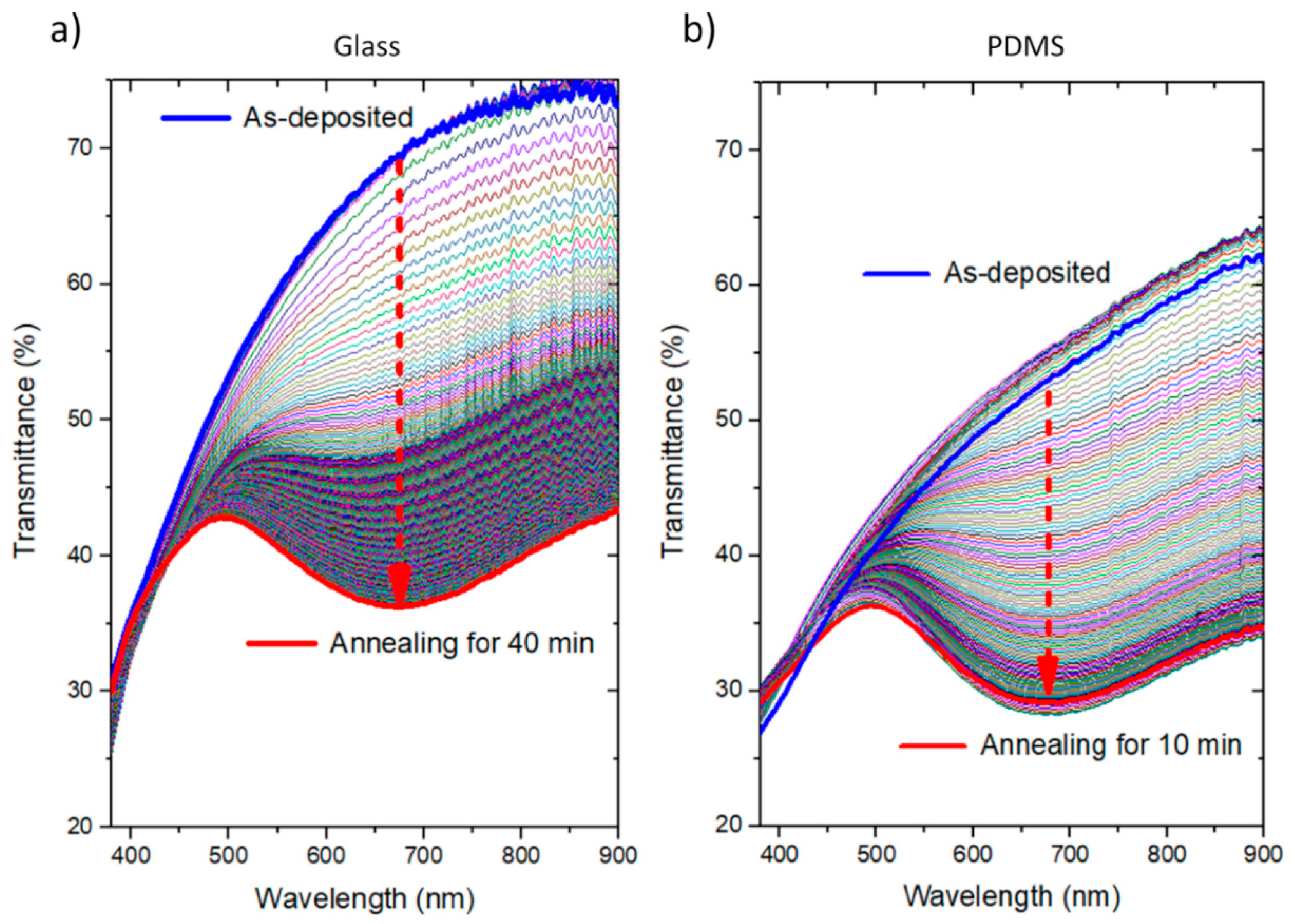
From RBS analysis, a gold concentration of 22.1 at.% dispersed into the TiO2 matrix was obtained. As a result of small-sized nanoparticles (below the quantum size limit [41]), the plasmonic absorption was very faint, and thus explains the absence of an LSPR band in the transmittance spectrum of the film, both for the films deposited onto glass or PDMS (Figure 2).
On the other hand, the host matrix where Au was embedded, was not crystallized after the deposition. Since the deposition process occurs at relatively low temperatures [60], the growing thin film is far from thermodynamic equilibrium, and thus it is expected to be highly disordered, leading to the formation of quasi-amorphous structures [61]. To promote a more efficient diffusion of Au throughout the matrix and induce the formation of Au nanoparticles, the thin films should be subjected to thermal annealing after the deposition. The heat treatment promotes some structural and morphological changes that are required to obtain an LSPR band [62].
The Au-TiO2 thin films, deposited onto PDMS and glass, for comparison, were heated up to 150 °C (the minimum temperature that permitted obtaining an LSPR band). The transmittance spectra were monitored in situ with the heat treatment for the duration of 40 min for the glass substrate, which allowed the minimum time to obtain a plasmonic band (about 10 min) to be selected. Afterwards, this heating time was employed to the Au-TiO2 film deposited on PDMS. The results are displayed in Figure 2, showing the transmittance spectrum evolution during the heating ramp for both substrates. As anticipated, the as-deposited thin film has a transmittance spectrum without any particular feature, regarding the presence of an LSPR band. Before the heat treatment, an important fraction of gold was still “dissolved” in the matrix, and the few Au nuclei that exist are of a few nm [41]. Under these conditions, quantum effects rule the optical properties; the LSPR band is still broad and damped and thus difficult to detect in transmittance mode [11].
As the temperature of the system was increased, the transmittance spectrum of the thin film suffered considerable changes, and the LSPR band started to be observed for temperatures below 150 °C. In the case of the film deposited onto the glass substrate, the transmittance minimum appears initially at about 640 nm, corresponding to a broad LSPR band, progressively shifting to higher wavelengths with increasing time, and temperature, towards 675 nm. After 40 min, the LSPR band profile was already comparable to what was achieved in a previous work (see also Figure 3), which already permits its use in LSPR sensing tests [38].
This is a significant result considering the importance of preparing plasmonic thin films at low temperature to be applied directly onto polymers. In this case, the polymer used was PDMS since it is transparent, usually used in microfluidic channels for the development of optical biosensors and T-LSPR systems. As can be perceivable from Figure 2b, a heating time of 10 min was enough to obtain a noticeable LSPR band. Although the transmittance of the PDMS substrate is lower than glass, the evolution of the transmittance band of both samples with heating time is rather similar, and thus it was expected that they have similar nanoparticles’ size distributions.
In addition, a small feature can be observed in the first seconds of the heat treatment of the Au-TiO2/PDMS sample, namely an increase of transmittance relatively to the as-deposited condition. This behavior is most probably related to some release of contaminants (e.g., hydrocarbons layer) lying at the back surface of the polymer.

3.2. Nanoparticles Distribution after Heat Treatment

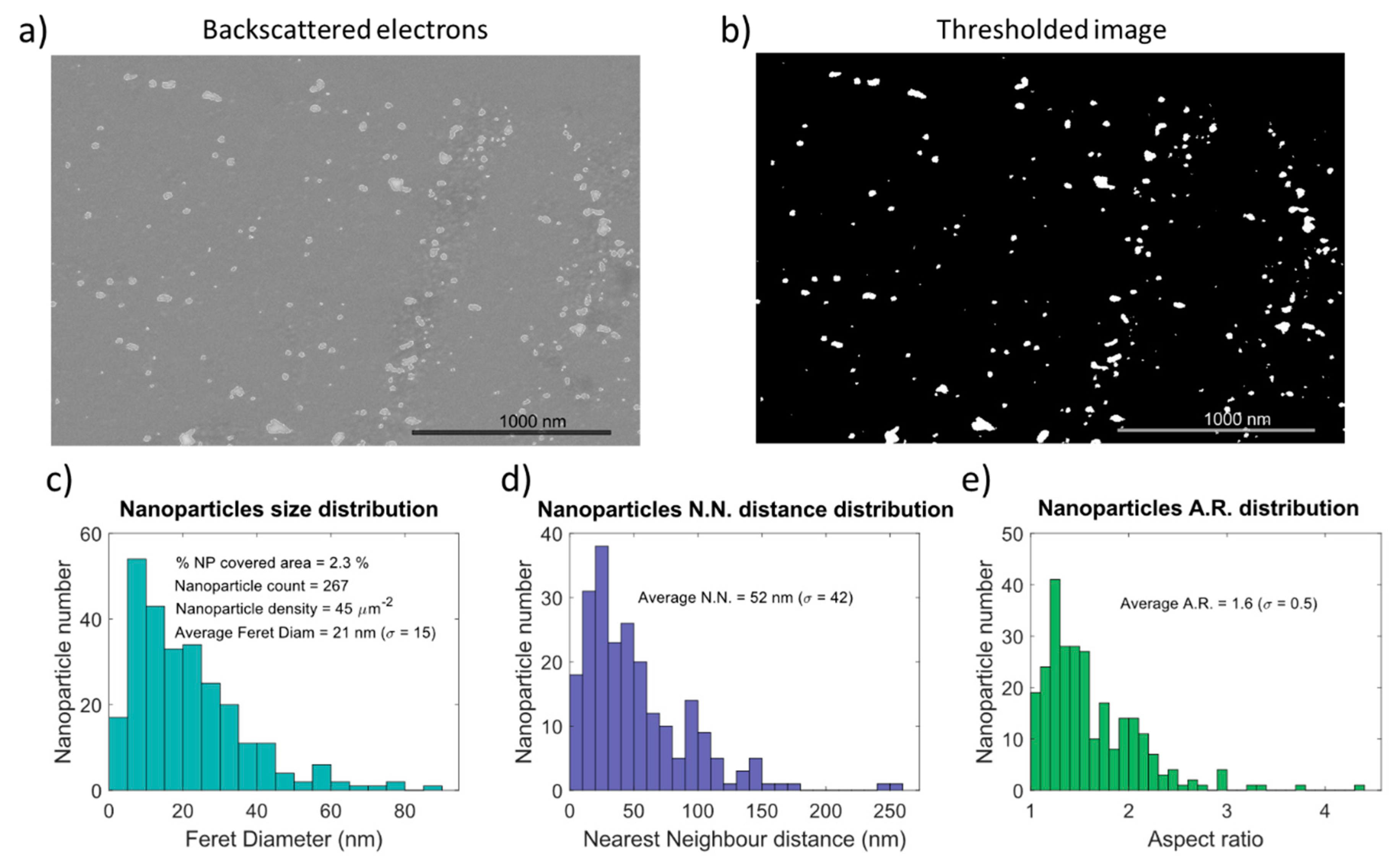
The surface of the thin film after the heat treatment (deposited on the glass substrate) was analyzed by SEM using chemical weight contrast (backscattered electrons). This allowed the sizes of the individual nanoparticles, their distribution throughout the surface of the film, and their shapes to be observed. This analysis was performed in top-view, since the basic principle of LSPR sensing requires an interaction between surface nanoparticles and targeted analyte.
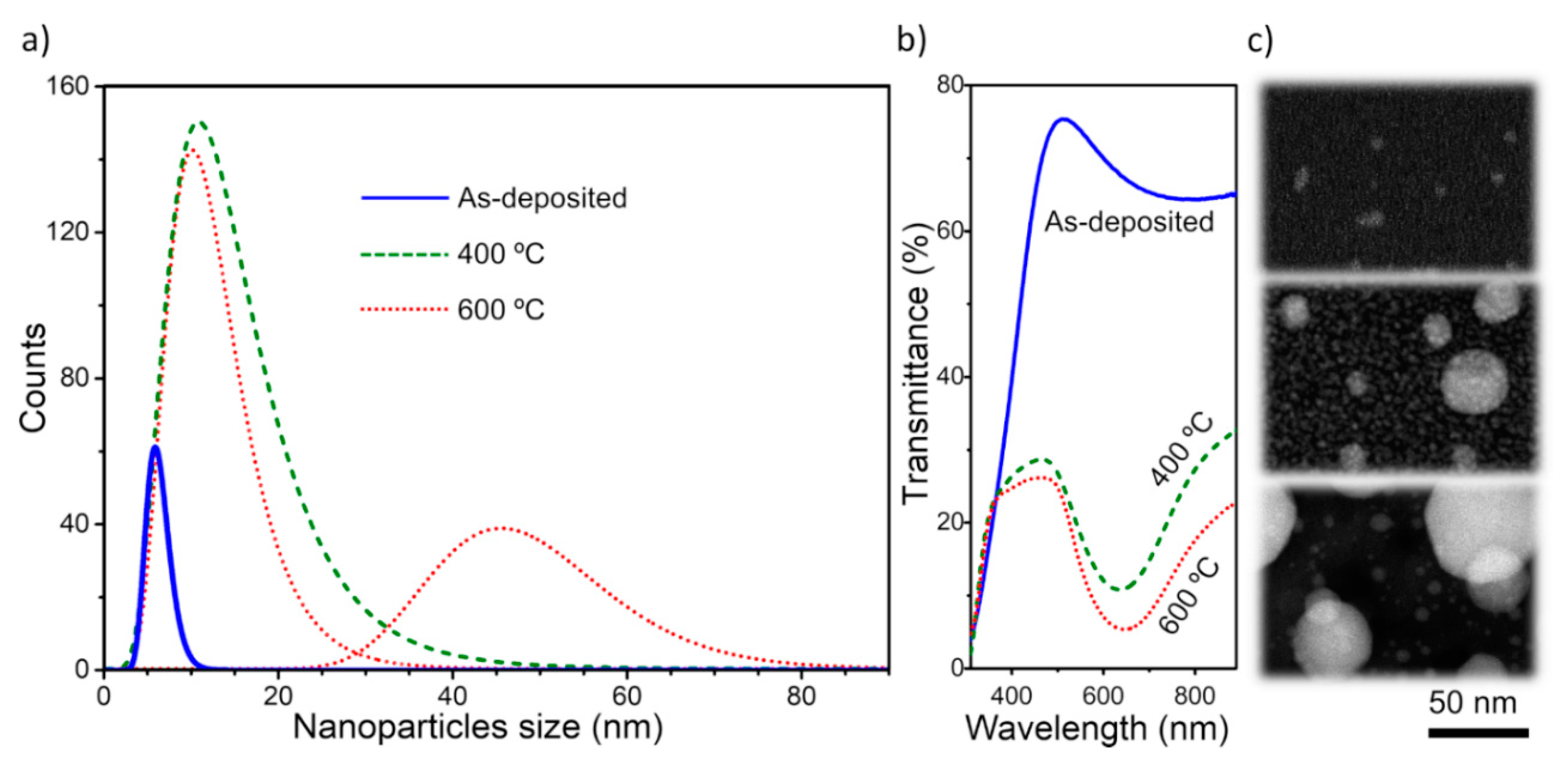
The influence of the annealing temperature on the nanoparticles size distribution in Au-TiO2 thin films was previously studied by transmission electron microscopy, in a recent work [41]. The analysis of the as-deposited Au-TiO2 thin film showed an early presence of a distribution of “small” nanoparticles with a size distribution typically up to 10 nm and an average size of 6.3 nm (Figure 3a,c). When the nanoparticles have these sizes, the plasmon resonances become more sensitive to quantum effects [11]. As a result, the LSPR peaks are too weak to be measured.
However, during the annealing treatment at 400 °C those “small-sized” nanoparticles, formed during the sputter deposition process itself, acted as nucleation sites for “normal growth” mechanisms. They gave rise to “intermediate” sizes from 10 to 40 nm, explaining the appearance of an LSPR band (Figure 3b). Furthermore, other nuclei were formed at the expense of Au atoms initially dispersed in the matrix (sizes below 10 nm), also contributing to the distribution. Nevertheless, it is believed that this group have negligible influence in the LSPR band, taking into account the behavior of the as-deposited sample. A further increase of the annealing temperature to 600 °C induced the formation of “big-sized” nanoparticles with an average size of 48 nm, resulting from coalescence and/or Ostwald ripening phenomena. Although the “intermediate-sized” group of nanoparticles were still present, the bimodal distribution (intermediate plus big-sized nanoparticles) (Figure 3a,c) originated a redshift and a small broadening of the LSPR (extinction) band due to a scattering effect of larger nanoparticles (Figure 3b) [41].
In the same way, and in order to quantify the Au nanoparticles exhibited in the thin film’s surface (annealed at 150 °C), the corresponding top-view micrograph (obtained using backscattered electrons, Figure 4a) was processed in the MATLAB software environment to produce thresholded black (matrix) and white (Au nanoparticles) regions (Figure 4b). The results for Feret diameter, nearest neighbor and aspect ratio distributions are plotted in the histograms in Figure 4. The average size of the nanoparticles is 21 nm, but with a relatively broad distribution (Figure 4c). This means that, under the used preparation conditions, it is possible to obtain a distribution of Au nanoparticles that agrees qualitatively and quantitatively with the results previously reported for an annealing temperature of 400 °C (see Figure 3 and Reference [41]). However, it is also perceivable that, on average, they are separated by higher distances (Figure 4d), and that their shapes are more irregular (Figure 4e). This effect is more evident for the larger nanoparticles, showing irregular and random shapes, which probably result from coalescence processes. During coalescence, some neighboring nanoparticles might merge into one, decreasing their number but creating larger and irregular nanoparticles, as can be observed in Figure 4a,b.
These results suggest that although these Au nanoparticles distribution gave rise to a well-defined LSPR band, some deposition parameters and heating conditions might be further optimized to obtain narrower distributions and higher covered areas.

3.3. Sensitivity Tests on the Au-TiO2 Thin Film Deposited onto PDMS

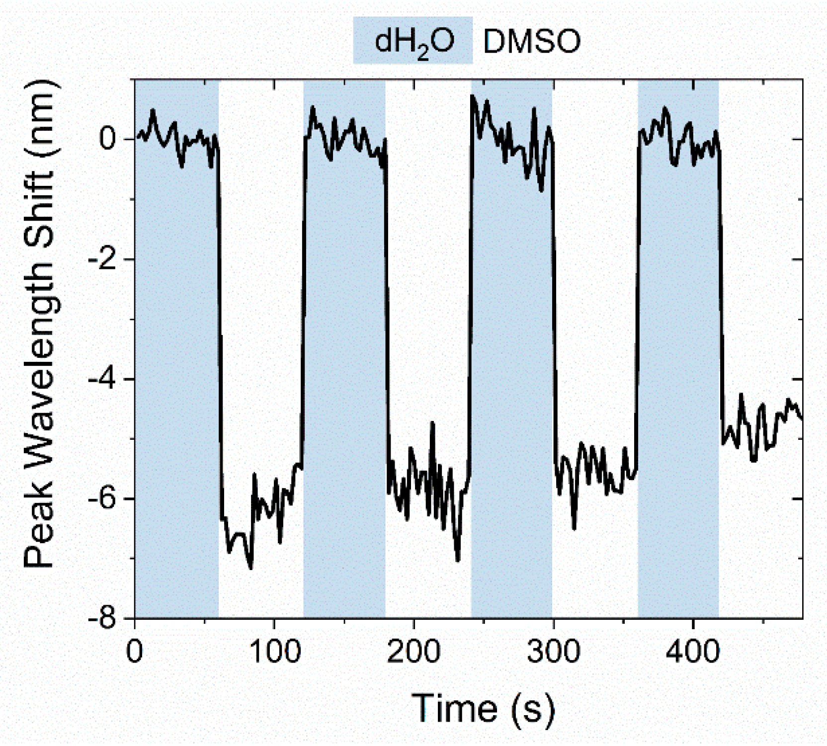
The sensitivity of the Au-TiO2 thin film, deposited in the polymer (PDMS) substrate, annealed at 150 °C, was evaluated by immersing it into two test fluids: i) Deionized water (H2O), and ii) DMSO, during several cycles. Since the chosen fluids exhibit different refractive indices, 1.333 RIU and 1.477 RIU (where RIU means refractive index units), it was possible to determine the refractive index sensitivity (RIS) of the plasmonic Au-TiO2 thin film. The RIS value was calculated based on a relation deduced in the literature [63] by considering an infinite layer of “analyte”, which simplifies the calculation in R I S = Δ λ / Δ η (nm/RIU), where Δ λ represents the peak wavelength shift and Δ η the difference of the refractive index of surrounding media.
In Figure 5, the peak wavelength shift observed in the transmittance spectrum of the film when it is immersed into the two fluids is shown. The RIS values were calculated from different cycles H2O/DMSO (each cycle with 1 min/ 1 min monitorization). The average absolute value is about 37.3 ± 1.5 nm/RIU, resulting from a blueshift when H2O is replaced by DMSO (average shift of 5.4 ± 0.2 nm).
According to SEM analysis (Figure 4), the number of surface nanoparticles is scarce, and this explains why the refractive index sensitivity of the film is not very high. Furthermore, the fact that the RIS is negative suggests that there are two contributions for the LSPR band of the thin film. One might be related to semi-exposed Au nanoparticles, while the second is associated to the Au nanoparticles totally embedded in the matrix. Indeed, it would be initially expected that the semi-exposed Au nanoparticles would respond with a redshift to positive variations in the refractive index of surrounding medium. Yet, the contribution of the Au nanoparticles totally embedded throughout the matrix is probably hindering significant changes of the LSPR band.

4. Conclusions

A simple, cost-effective and versatile preparation method was used to produce plasmonic thin films of Au-TiO2 on a transparent polymer substrate (PDMS). It consists, as a first step, of the deposition of an oxide (TiO2) thin film and the incorporation of Au atoms in this matrix by reactive DC magnetron sputtering. In a second step, a heat treatment was required to promote the growth of the Au nanoparticles. Due to temperature restrictions, the maximum heating temperature was relatively low, i.e., 150 °C. However, the average size of Au nanoparticles was estimated to be about 21 nm, and the corresponding size distribution was convenient for the envisaged application, the number of nanoparticles was still scarce (at the surface), and a considerable number had irregular shape. So, their recrystallization was probably not completed. Yet, the formation of these Au nanoparticles was responsible for the manifestation of the LSPR phenomenon, observed as a transmittance minimum in the visible spectrum. The transmittance spectrum of the thin film was monitored in situ during the heat-treatment and it was possible to observe the appearance, and evolution, of the LSPR band during the 10 minutes of heat treatment.
After a standard sensitivity test, the Au-TiO2 films showed some sensitivity to refractive index changes, in the order of a few tens of nm/RIU (in the same order of magnitude of this type of thin films, using other matrixes). To improve the sensitivity to hundreds of nm/RIU (desirable for high-resolution systems) the nanostructure of the film must be further tailored, either by changing the deposition parameters, or by optimizing the heating treatment conditions. In fact, the deposition of thin films with inclined architectures (using glancing angle deposition), and the application of a surface plasma treatment, to enhance the number of exposed nanoparticles, might improve the sensitivity of the nanoplasmonic thin film.
This work shows that it is possible to produce plasmonic Au-TiO2 thin films in transparent polymer substrates such as PDMS. Since PDMS can be used as a film’s substrate and, also, is the base material for microfluidic channels, an LSPR sensing system based on a plasmonic thin film deposited in polymer substrate can have several advantages. This is a promising step for the development of an optical (bio)sensitive platform based on the plasmonic effect of Au-TiO2 thin film. Furthermore, due to the flexible nature of the PDMS substrate a new field of LSPR-based sensors and plasmon-enhanced applications can be explored.

Author Contributions

Conceptualization, J.B.; methodology, M.S.R. and J.B.; software, M.S.R.; validation, J.B.; formal analysis, M.S.R. and D.I.M.; investigation, M.S.R., D.I.M. and C.L.; resources, J.B and F.V.; data curation, M.S.R. and J.B.; writing—original draft preparation, J.B.; writing—review and editing, C.L., J.B. and F.V.; visualization, M.S.R., D.I.M. and J.B.; supervision, J.B. and F.V.; project administration, J.B. and F.V.; funding acquisition, J.B. and F.V. All authors have read and agreed to the published version of the manuscript.

Funding

This research was funded by the Portuguese Foundation for Science and Technology (FCT), co-financed by European Regional Development Fund (ERDF), in the framework of the Strategic Funding, grant number UID/FIS/04650/2019; also by the project NANOSENSING, grant number POCI-01-0145-FEDER-016902 and FCT reference PTDC/FIS-NAN/1154/2014; and by the project NANO4BIO, grant number POCI-01-0145-FEDER-032299 and FCT reference PTDC/FIS-MAC/32299/2017.

Acknowledgments

Joel Borges acknowledges the Portuguese Foundation for Science and Technology (FCT) for his Researcher Contract from project NANO4BIO (grant number POCI-01-0145-FEDER-032299 and FCT reference PTDC/FIS-MAC/32299/2017). Diana I. Meira acknowledges FCT for her PhD Scholarship, SFRH/BD/143262/2019. Marco S. Rodrigues acknowledges FCT for his PhD Scholarship, SFRH/BD/118684/2016. Cláudia Lopes acknowledges her post-doctoral fellowship from project NANOSENSING (POCI-01-0145-FEDER-016902 and FCT reference PTDC/FIS-NAN/1154/2014).

Conflicts of Interest

The authors declare no conflict of interest

References

  1. Willets, K.A.; Van Duyne, R.P. Localized Surface Plasmon Resonance Spectroscopy and Sensing. Annu. Rev. Phys. Chem. 2007, 58, 267–297. [Google Scholar] [CrossRef] [PubMed] [Green Version]
  2. Kristensen, A.; Yang, J.K.W.; Bozhevolnyi, S.I.; Link, S.; Nordlander, P.; Halas, N.J.; Mortensen, N.A. Plasmonic colour generation. Nat. Rev. Mater. 2016, 2, 16088. [Google Scholar] [CrossRef] [Green Version]
  3. Barber, D.J.; Freestone, I.C. An investigation of the origin of the colour of the lycurgus cup by analytical transmission electron microscopy. Archaeometry 1990, 32, 33–45. [Google Scholar] [CrossRef]
  4. Stockman, M.I. Nanoplasmonics: The physics behind the applications. Phys. Today 2011, 64, 39–44. [Google Scholar] [CrossRef] [Green Version]
  5. Gonçalves, M.R. Plasmonic nanoparticles: fabrication, simulation and experiments. J. Phys. D. Appl. Phys. 2014, 47, 213001. [Google Scholar] [CrossRef]
  6. Pitarke, J.M.; Silkin, V.M.; Chulkov, E.V.; Echenique, P.M. Theory of surface plasmons and surface-plasmon polaritons. Reports Prog. Phys. 2007, 70, 1–87. [Google Scholar] [CrossRef]
  7. McQuillan, A.J. The discovery of surface-enhanced Raman scattering. Notes Rec. R. Soc. 2009, 63, 105–109. [Google Scholar] [CrossRef]
  8. Kahl, P.; Podbiel, D.; Schneider, C.; Makris, A.; Sindermann, S.; Witt, C.; Kilbane, D.; Hoegen, M.H.; Aeschlimann, M.; zu Heringdorf, F.M. Direct Observation of Surface Plasmon Polariton Propagation and Interference by Time-Resolved Imaging in Normal-Incidence Two Photon Photoemission Microscopy. Plasmonics 2018, 13, 239–246. [Google Scholar] [CrossRef]
  9. Li, D.-B.; Sun, X.-J.; Jia, Y.-P.; Stockman, M.I.; Paudel, H.P.; Song, H.; Jiang, H.; Li, Z.-M. Direct observation of localized surface plasmon field enhancement by Kelvin probe force microscopy. Light Sci. Appl. 2017, 6, e17038. [Google Scholar] [CrossRef]
  10. Toudert, J.; Simonot, L.; Camelio, S.; Babonneau, D. Advanced optical effective medium modeling for a single layer of polydisperse ellipsoidal nanoparticles embedded in a homogeneous dielectric medium: Surface plasmon resonances. Phys. Rev. B 2012, 86, 45415. [Google Scholar] [CrossRef] [Green Version]
  11. Scholl, J.A.; Koh, A.L.; Dionne, J.A. Quantum plasmon resonances of individual metallic nanoparticles. Nature 2012, 483, 421–427. [Google Scholar] [CrossRef] [PubMed]
  12. Dionne, J.A.; Baldi, A.; Baum, B.; Ho, C.-S.; Janković, V.; Naik, G.V.; Narayan, T.; Scholl, J.A.; Zhao, Y. Localized fields, global impact: Industrial applications of resonant plasmonic materials. MRS Bull. 2015, 40, 1138–1145. [Google Scholar] [CrossRef] [Green Version]
  13. Stockman, M.I.; Kneipp, K.; Bozhevolnyi, S.I.; Saha, S.; Dutta, A.; Ndukaife, J.; Kinsey, N.; Reddy, H.; Guler, U.; Shalaev, V.M.; et al. Roadmap on plasmonics. J. Opt. 2018, 20, 043001. [Google Scholar] [CrossRef] [Green Version]
  14. Giannini, V.; Fernández-Domínguez, A.I.; Heck, S.C.; Maier, S.A. Plasmonic Nanoantennas: Fundamentals and Their Use in Controlling the Radiative Properties of Nanoemitters. Chem. Rev. 2011, 111, 3888–3912. [Google Scholar] [CrossRef] [PubMed]
  15. Anker, J.N.; Hall, W.P.; Lyandres, O.; Shah, N.C.; Zhao, J.; Van Duyne, R.P. Biosensing with plasmonic nanosensors. Nat. Mater. 2008, 7, 442–453. [Google Scholar] [CrossRef]
  16. Guo, L.; Jackman, J.A.; Yang, H.H.; Chen, P.; Cho, N.J.; Kim, D.H. Strategies for enhancing the sensitivity of plasmonic nanosensors. Nano Today 2015, 10, 213–239. [Google Scholar] [CrossRef] [Green Version]
  17. Kazuma, E.; Tatsuma, T. Localized surface plasmon resonance sensors based on wavelength-tunable spectral dips. Nanoscale 2014, 6, 2397–2405. [Google Scholar] [CrossRef] [Green Version]
  18. Sannomiya, T.; Vörös, J. Single plasmonic nanoparticles for biosensing. Trends Biotechnol. 2011, 29, 343–351. [Google Scholar] [CrossRef]
  19. Piliarik, M.; Šípová, H.; Kvasnička, P.; Galler, N.; Krenn, J.R.; Homola, J. High-resolution biosensor based on localized surface plasmons. Opt. Express 2012, 20, 672. [Google Scholar] [CrossRef]
  20. Soler, M.; Huertas, C.S.; Lechuga, L.M. Label-free plasmonic biosensors for point-of-care diagnostics: a review. Expert Rev. Mol. Diagn. 2019, 19, 71–81. [Google Scholar] [CrossRef]
  21. Cappi, G.; Spiga, F.M.; Moncada, Y.; Ferretti, A.; Beyeler, M.; Bianchessi, M.; Decosterd, L.; Buclin, T.; Guiducci, C. Label-Free Detection of Tobramycin in Serum by Transmission-Localized Surface Plasmon Resonance. Anal. Chem. 2015, 87, 5278–5285. [Google Scholar] [CrossRef] [PubMed]
  22. Li, J.-F.; Li, C.-Y.; Aroca, R.F. Plasmon-enhanced fluorescence spectroscopy. Chem. Soc. Rev. 2017, 46, 3962–3979. [Google Scholar] [CrossRef] [PubMed]
  23. Rao, V.K.; Radhakrishnan, T.P. Tuning the SERS Response with Ag-Au Nanoparticle-Embedded Polymer Thin Film Substrates. ACS Appl. Mater. Interfaces 2015, 7, 12767–12773. [Google Scholar] [CrossRef] [PubMed]
  24. Solís, D.M.; Taboada, J.M.; Obelleiro, F.; Liz-Marzán, L.M.; García de Abajo, F.J. Optimization of Nanoparticle-Based SERS Substrates through Large-Scale Realistic Simulations. ACS Photonics 2017, 4, 329–337. [Google Scholar] [CrossRef] [Green Version]
  25. Oh, Y.-J.; Jeong, K.-H. Optofluidic SERS chip with plasmonic nanoprobes self-aligned along microfluidic channels. Lab Chip 2014, 14, 865–868. [Google Scholar] [CrossRef]
  26. Zhang, S.; Liu, M.; Liu, W.; Liu, Y.; Li, Z.; Wang, X.; Yang, F. Absorption enhancement in thin film solar cells with bilayer silver nanoparticle arrays. J. Phys. Commun. 2018, 2, 055032. [Google Scholar] [CrossRef]
  27. Liu, W.-L.; Lin, F.-C.; Yang, Y.-C.; Huang, C.-H.; Gwo, S.; Huang, M.H.; Huang, J.-S. The influence of shell thickness of Au@TiO2 core–shell nanoparticles on the plasmonic enhancement effect in dye-sensitized solar cells. Nanoscale 2013, 5, 7953. [Google Scholar] [CrossRef]
  28. Wang, W.; Zhang, J.; Che, X.; Qin, G. Large Absorption Enhancement in Ultrathin Solar Cells Patterned by Metallic Nanocavity Arrays. Sci. Rep. 2016, 6, 34219. [Google Scholar] [CrossRef] [Green Version]
  29. Kim, I.; Seok Jeong, D.; Seong Lee, T.; Seong Lee, W.; Lee, K.-S. Plasmonic absorption enhancement in organic solar cells by nano disks in a buffer layer. J. Appl. Phys. 2012, 111, 103121. [Google Scholar] [CrossRef]
  30. Peng, Y.; Xiong, B.; Peng, L.; Li, H.; He, Y.; Yeung, E.S. Recent Advances in Optical Imaging with Anisotropic Plasmonic Nanoparticles. Anal. Chem. 2015, 87, 200–215. [Google Scholar] [CrossRef]
  31. Kim, S.-E.; Lee, B.-R.; Lee, H.; Jo, S.D.; Kim, H.; Won, Y.-Y.; Lee, J. Near-Infrared Plasmonic Assemblies of Gold Nanoparticles with Multimodal Function for Targeted Cancer Theragnosis. Sci. Rep. 2017, 7, 17327. [Google Scholar] [CrossRef] [PubMed] [Green Version]
  32. Mendes, R.; Pedrosa, P.; Lima, J.C.; Fernandes, A.R.; Baptista, P.V. Photothermal enhancement of chemotherapy in breast cancer by visible irradiation of Gold Nanoparticles. Sci. Rep. 2017, 7, 10872. [Google Scholar] [CrossRef] [PubMed]
  33. Ma, X.C.; Dai, Y.; Yu, L.; Huang, B.B. Energy transfer in plasmonic photocatalytic composites. Light Sci. Appl. 2016, 5, e16017. [Google Scholar] [CrossRef] [PubMed] [Green Version]
  34. Zhang, X.; Chen, Y.L.; Liu, R.S.; Tsai, D.P. Plasmonic photocatalysis. Reports Prog. Phys. 2013, 76, 046401. [Google Scholar] [CrossRef] [PubMed] [Green Version]
  35. Singh, J.; Satpati, B.; Mohapatra, S. Structural, Optical and Plasmonic Properties of Ag-TiO2 Hybrid Plasmonic Nanostructures with Enhanced Photocatalytic Activity. Plasmonics 2017, 12, 877–888. [Google Scholar] [CrossRef]
  36. Kuriakose, S.; Sahu, K.; Khan, S.A.; Tripathi, A.; Avasthi, D.K.; Mohapatra, S. Facile synthesis of Au-ZnO plasmonic nanohybrids for highly efficient photocatalytic degradation of methylene blue. Opt. Mater. 2017, 64, 47–52. [Google Scholar] [CrossRef]
  37. Reddy, N.L.; Rao, V.N.; Vijayakumar, M.; Santhosh, R.; Anandan, S.; Karthik, M.; Shankar, M.V.; Reddy, K.R.; Shetti, N.P.; Nadagouda, M.N.; et al. A review on frontiers in plasmonic nano-photocatalysts for hydrogen production. Int. J. Hydrogen Energy 2019, 44, 10453–10472. [Google Scholar] [CrossRef]
  38. Rodrigues, M.S.; Borges, J.; Proença, M.; Pedrosa, P.; MARTIN, N.; Romanyuk, K.; Kholkin, A.L.; Vaz, F. Nanoplasmonic response of porous Au-TiO2 thin films prepared by oblique angle deposition. Nanotechnology 2019, 30, 225701. [Google Scholar] [CrossRef]
  39. Proença, M.; Rodrigues, M.S.; Borges, J.; Vaz, F. Gas Sensing with Nanoplasmonic Thin Films Composed of Nanoparticles (Au, Ag) Dispersed in a CuO Matrix. Coatings 2019, 9, 337. [Google Scholar] [CrossRef] [Green Version]
  40. Barbosa, A.I.; Borges, J.; Meira, D.I.; Costa, D.; Rodrigues, M.S.; Rebelo, R.; Correlo, V.M.; Vaz, F.; Reis, R.L. Development of label-free plasmonic Au-TiO2 thin film immunosensor devices. Mater. Sci. Eng. C 2019, 100, 424–432. [Google Scholar] [CrossRef]
  41. Koneti, S.; Borges, J.; Roiban, L.; Rodrigues, M.S.; Martin, N.; Epicier, T.; Vaz, F.; Steyer, P. Electron Tomography of Plasmonic Au Nanoparticles Dispersed in a TiO2 Dielectric Matrix. ACS Appl. Mater. Interfaces 2018, 10, 42882–42890. [Google Scholar] [CrossRef] [PubMed]
  42. Chen, P.; Liedberg, B. Curvature of the Localized Surface Plasmon Resonance Peak. Anal. Chem. 2014, 86, 7399–7405. [Google Scholar] [CrossRef]
  43. Lopez, G.A.; Estevez, M.C.; Soler, M.; Lechuga, L.M. Recent advances in nanoplasmonic biosensors: Applications and lab-on-a-chip integration. Nanophotonics 2017, 6, 123–136. [Google Scholar] [CrossRef]
  44. Niu, L.; Zhang, N.; Liu, H.; Zhou, X.; Knoll, W. Integrating plasmonic diagnostics and microfluidics. Biomicrofluidics 2015, 9, 052611. [Google Scholar] [CrossRef] [Green Version]
  45. SadAbadi, H.; Badilescu, S.; Packirisamy, M.; Wüthrich, R. Integration of gold nanoparticles in PDMS microfluidics for lab-on-a-chip plasmonic biosensing of growth hormones. Biosens. Bioelectron. 2013, 44, 77–84. [Google Scholar] [CrossRef]
  46. Liu, Y.; Xie, S.; Xiao, X.; Li, S.; Gao, F.; Zhang, Z.; Du, J. Fabricating metal nanoparticle arrays at specified and localized regions of microfluidic chip for LSPR sensing. Microelectron. Eng. 2016, 151, 7–11. [Google Scholar] [CrossRef]
  47. Zhang, Y.; Tang, Y.; Hsieh, Y.-H.; Hsu, C.-Y.; Xi, J.; Lin, K.-J.; Jiang, X. Towards a high-throughput label-free detection system combining localized-surface plasmon resonance and microfluidics. Lab Chip 2012, 12, 3012. [Google Scholar] [CrossRef] [PubMed] [Green Version]
  48. Giesfeldt, K.S.; Connatser, R.M.; De Jesús, M.A.; Dutta, P.; Sepaniak, M.J. Gold-polymer nanocomposites: studies of their optical properties and their potential as SERS substrates. J. Raman Spectrosc. 2005, 36, 1134–1142. [Google Scholar] [CrossRef]
  49. Olavarría-Fullerton, J.; De Jesús, M.A.; Sepaniak, M.J.; Velez, R.A.; Wells, S.; Hernández-Rivera, S.P. Design and Characterization of Hybrid Morphology Nanoarrays as Plasmonic Raman Probes for Antimicrobial Detection. Appl. Spectrosc. 2013, 67, 1315–1322. [Google Scholar] [CrossRef]
  50. Pinto, V.; Sousa, P.; Catarino, S.O.; Correia-Neves, M.; Minas, G. Microfluidic immunosensor for rapid and highly-sensitive salivary cortisol quantification. Biosens. Bioelectron. 2017, 90, 308–313. [Google Scholar] [CrossRef] [Green Version]
  51. Faustino, V.; Catarino, S.O.; Lima, R.; Minas, G. Biomedical microfluidic devices by using low-cost fabrication techniques: A review. J. Biomech. 2016, 49, 2280–2292. [Google Scholar] [CrossRef] [PubMed] [Green Version]
  52. Connatser, R.M.; Riddle, L.A.; Sepaniak, M.J. Metal-polymer nanocomposites for integrated microfluidic separations and surface enhanced Raman spectroscopic detection. J. Sep. Sci. 2004, 27, 1545–1550. [Google Scholar] [CrossRef] [PubMed]
  53. Kim, D.; Herr, A.E. Protein immobilization techniques for microfluidic assays. Biomicrofluidics 2013, 7, 041501. [Google Scholar] [CrossRef] [PubMed] [Green Version]
  54. Geng, Z.; Liu, W.; Wang, X.; Yang, F. A route to apply Ag nanoparticle array integrated with microfluidic for surface enhanced Raman scattering. Sensors Actuators A Phys. 2011, 169, 37–42. [Google Scholar] [CrossRef]
  55. Lee, S.Y.; Walsh, G.F.; Dal Negro, L. Microfluidics integration of aperiodic plasmonic arrays for spatial-spectral optical detection. Opt. Express 2013, 21, 4945. [Google Scholar] [CrossRef]
  56. Rodrigues, M.S.; Costa, D.; Domingues, R.P.; Apreutesei, M.; Pedrosa, P.; Martin, N.; Correlo, V.M.; Reis, R.L.; Alves, E.; Barradas, N.P.; et al. Optimization of nanocomposite Au/TiO2 thin films towards LSPR optical-sensing. Appl. Surf. Sci. 2018, 438, 74–83. [Google Scholar] [CrossRef]
  57. Barradas, N.P.; Jeynes, C.; Webb, R.P. Simulated annealing analysis of Rutherford backscattering data. Appl. Phys. Lett. 1997, 71, 291–293. [Google Scholar] [CrossRef] [Green Version]
  58. Barradas, N.P.; Pascual-Izarra, C. Double scattering in RBS analysis of PtSi thin films on Si. Nucl. Instruments Methods Phys. Res. Sect. B Beam Interact. with Mater. Atoms 2005, 228, 378–382. [Google Scholar] [CrossRef]
  59. Barradas, N.P.; Reis, M.A. Accurate calculation of pileup effects in PIXE spectra from first principles. X-Ray Spectrom. 2006, 35, 232–237. [Google Scholar] [CrossRef]
  60. Borges, J.; Martin, N.; Vaz, F.; Marques, L. Process monitoring during AlNxOy deposition by reactive magnetron sputtering and correlation with the film’s properties. J. Vac. Sci. Technol. A Vac. Surf. Film. 2014, 32, 021307. [Google Scholar] [CrossRef] [Green Version]
  61. Borges, J.; Buljan, M.; Sancho-Parramon, J.; Bogdanovic-Radovic, I.; Siketic, Z.; Scherer, T.; Kübel, C.; Bernstorff, S.; Cavaleiro, A.; Vaz, F.; et al. Evolution of the surface plasmon resonance of Au:TiO2 nanocomposite thin films with annealing temperature. J. Nanoparticle Res. 2014, 16, 2790. [Google Scholar] [CrossRef]
  62. Borges, J.; Pereira, R.M.S.; Rodrigues, M.S.; Kubart, T.; Kumar, S.; Leifer, K.; Cavaleiro, A.; Polcar, T.; Vasilevskiy, M.I.; Vaz, F. Broadband Optical Absorption Caused by the Plasmonic Response of Coalesced Au Nanoparticles Embedded in a TiO2 Matrix. J. Phys. Chem. C 2016, 120, 16931–16945. [Google Scholar] [CrossRef]
  63. Kedem, O.; Vaskevich, A.; Rubinstein, I. Critical Issues in Localized Plasmon Sensing. J. Phys. Chem. C 2014, 118, 8227–8244. [Google Scholar] [CrossRef]
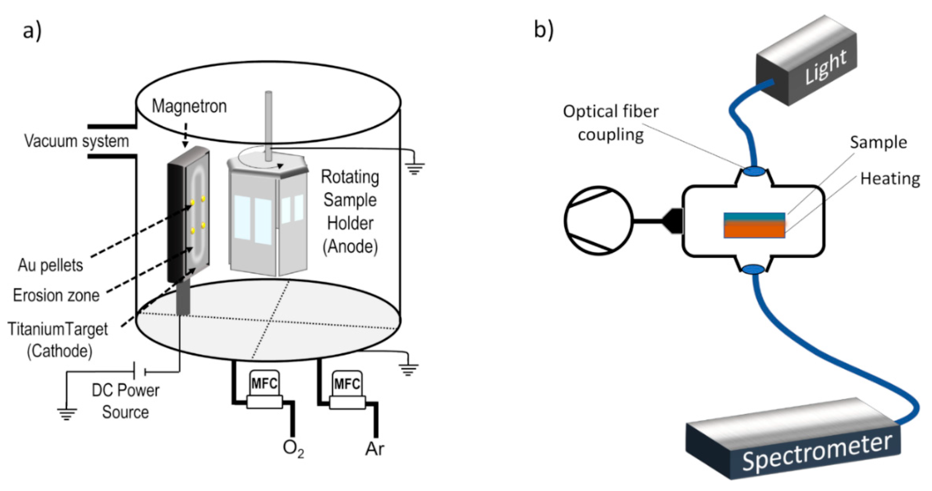
Figure 1. Simplified schematics of (a) the magnetron sputtering deposition system, and (b) custom-made optical system for transmittance-LSPR measurements in controlled atmosphere and temperature.
Coatings 10 00227 g001
Figure 2. Transmittance spectrum of Au-TiO2 thin films deposited onto (a) glass, and (b) PDMS substrates, monitored in situ with heat treatment in vacuum (P~ 10 Pa), from room temperature to 150 °C.
Coatings 10 00227 g002
Figure 3. (a) Size distribution of Au nanoparticles embedded in a TiO2 matrix for different annealing temperature conditions, (b) corresponding transmittance spectra, and (c) transmission electron microscopy images of the thin films.
Coatings 10 00227 g003
Figure 4. Nanoparticle distribution analysis: (a) Shows the top-view SEM micrograph with atomic weight contrast, and (b) depicts the processed and thresholded micrographs evidencing the Au nanoparticles. Distribution histograms are also displayed in (c) for nanoparticles Feret diameter, (d) for nearest neighbor distance, and (e) for aspect ratio.
Coatings 10 00227 g004
Figure 5. Peak wavelength shift of the Au-TiO2 thin film (annealed at 150 °C), during H2O/DMSO cycles.
Coatings 10 00227 g005