Article

Properties of a Plasma-Nitrided Coating and a CrNx Coating on the Stainless Steel Bipolar Plate of PEMFC

School of Materials and Metallurgy, University of Science and Technology Liaoning, Anshan 114051, China
*
Author to whom correspondence should be addressed.
Coatings 2020, 10(2), 183; https://doi.org/10.3390/coatings10020183
Submission received: 11 January 2020 / Revised: 8 February 2020 / Accepted: 14 February 2020 / Published: 17 February 2020
(This article belongs to the Section Surface Characterization, Deposition and Modification)

Abstract

:
PEMFC are considered to be the most promising for automotive energy because of their good working effect, low temperature, high efficiency, and zero pollution. Stainless steel as a PEMFC bipolar plate has unparalleled advantages in strength, cost, and processability, but it is easy to corrode in a PEMFC working environment. In order to improve the corrosion resistance, the surface modification of 316L stainless steel is a feasible solution for PEMFC bipolar plates. In the present study, the plasma-nitrided coating and CrNx coating were prepared by the plasma-enhanced balanced magnetron sputtering technology on the 316L stainless steel surface. The microstructures, phase compositions, and corrosion resistance behavior of the coatings were investigated. The corrosion behavior of the prepared plasma-nitrided coating and CrNx coating was investigated by potentiodynamic polarization, potentiostatic polarization, and electrochemical impedance spectroscopy (EIS) in both cathodic and anodic environments. The experimental results show that corrosion resistance of the CrNx coating was better than the plasma-nitrided coating. It was indicated that the technology process of nitriding first and then depositing Cr was better than nitriding only.

1. Introduction

Fuel cells are electrochemical devices that convert the chemical energy of a reaction directly into electrical energy [1]. PEMFC is one of the most promising candidates for vehicular power sources and for domestic combined heat and power (CHP) systems. The PEMFC operates at a low temperature (60–80 °C) and has a high specific power and compactness. It consisted of membrane electrode assembly and bipolar plates. Bipolar plates are one of the core components of PEMFC and provide electrical connections from one battery to another. They also evenly distribute reaction gases through the flow field, conduct current from each cell, and promote residual water discharge from the cell outlet for thermal management [2,3,4,5]. It is proved that bipolar plates account for 80%–85% of the total weight and 30% of the total cost of PEMFC stacks [6,7]. Therefore, it is important to simultaneously reduce the weight and the cost of bipolar plate materials. Bipolar plates possess the characteristics of high chemical stability, high corrosion resistance, high conductivity, low contact resistance, good mechanical strength, and low permeability. However, very few materials can satisfy all these properties of bipolar plates [8,9,10]. Stainless steel is the most commonly used bipolar plate material, but it easily forms a passive film in the bipolar plate working environment, which caused an increase in the contact resistance and a reduction in the corrosion resistance of bipolar plates. Therefore, a coating with strong adhesion, compact structure, good corrosion resistance, and strong conductivity is usually prepared on the stainless steel surface [11,12,13,14,15].
Different surface modification techniques, such as physical vapor deposition (PVD) [16,17,18,19,20,21], chemical vapor deposition (CVD), plasma coating [22], and surface plasma nitridation [23,24,25,26], have been employed to deposit coatings on the stainless steel surface. Plasma-nitrided PVD coatings can increase the corrosion resistance and also significantly reduce the contact resistance of bipolar plates. Oladijo et al. [27] employed the plasma spraying technology to deposit a zinc-based alloy coating on the low-carbon steel matrix and found that zinc-based alloy coated low-carbon steel yielded improved corrosion resistance and microhardness in comparison to uncoated low-carbon steel. Metal plasma nitrides (CrN, TiN, and Cr/TiN) with good corrosion resistance, excellent interface conductivity, and low cost [28,29,30] are known as potential materials for surface modification. Zhang et al. [31] reported that when the contact resistance of the hard CrN coating reached the minimum value, the nitrogen content in the coating was about 35% [32,33,34,35,36,37].
In this study, the plasma-nitrided coating and CrNx coating are deposited on 316L stainless steel by plasma-enhanced balanced magnetron sputtering technology. The microstructure and phase structure patterns of coatings are investigated by scanning electron microscope (SEM) and X-ray diffraction. The corrosion behavior of the plasma-nitrided and CrNx are coated on the 316L stainless steel and is investigated by the electrochemical method. The ICR is also evaluated before and after potentiostatic polarization at anodic/cathodic operation potential for PEMFC. The performance of corrosion resistance and surface morphologies of the plasma-nitrided coating and CrNx coating were compared.

2. Experimental

2.1. Materials and Specimen Preparation

316L austenitic stainless steel was selected as the matrix, and its chemical composition is presented in Table 1. The 316L austenitic stainless steel matrix was first cut into Φ30 mm × 3 mm cylinders by wire cutting. The samples were then put into a mixed solution of ethanol and acetone for ultrasonic cleaning. After that, the samples were polished on the polishing machine at a constant speed for 3–4 min at one third of the center of the circle, and then water polishing for 2 min until there is no obvious scratch on the surface. Subsequently, the samples were cleaned in acetone with ultrasonic vibration for 10 min.

2.2. Deposition of the Coating

Plasma-nitrided coating and CrNx coating were deposited on 316L stainless steel by magnetron sputtering technology. The plasma-nitrided coating was deposited under an N2 gas nitrogen flow of 200 sscm at 380 °C, a filament current 6 A, and deposition time of 2 h. The CrNx coating is prepared on the basis of the plasma-nitrided coating. After the plasma-nitrided coating was prepared, the CrNx coating was deposited under an Ar gas flow of 100 sscm and the deposition time of 10 min. The plasma-nitrided coating was formed on the stainless steel first, and the Cr layer was formed on the nitriding layer. All specimens were cooled to room temperature in vacuum conditions.

2.3. Electrochemical and Contact Resistance Tests

In the simulated PEMFC environment, an AutoLab electrochemical workstation (CHI600E, Japan Shimadzu Co., Ltd., Tokyo, Japan) was used to test the corrosion resistance of the matrix and the coatings through potentiodynamic polarization, potentiostatic polarization, and impedance spectroscopy (EIS). In the present experiment, a three-electrode system was used. The sample acted as the working electrode (WE), the platinum electrode served as the counter electrode (CE), and the saturated calomel electrode acted as the reference electrode (RE). The solution (0.5 mol/L H2SO4 + 5 ppm HF) was used to simulate the corrosive environment of PEMFC during the experiment. The method for measurement of the ICR between stainless steel and gas diffusion layer (carbon paper) described by Feng et al. [38] was used in this study. When an electrical current (100 mA) was passed through the two copper plates, the voltage between the two copper plates was recorded. The ICR was calculated by the Ohm’s law.

2.4. Surface Morphology Analysis

The microstructure and chemical composition of the samples were investigated by a scanning electron microscope (SEM, JSM-6390A, Joint-stock Company, Beijing, China) and an energy dispersive spectrometer (EDS, JSM-6390A, Joint-stock Company, Beijing, China). Chemical structures of coatings were investigated by X-ray diffraction (XRD, LabX XRD-6000, Japan Shimadzu Co., Ltd., Tokyo, Japan) under a scanning angle of 30°–110°.

3. Results and Discussion

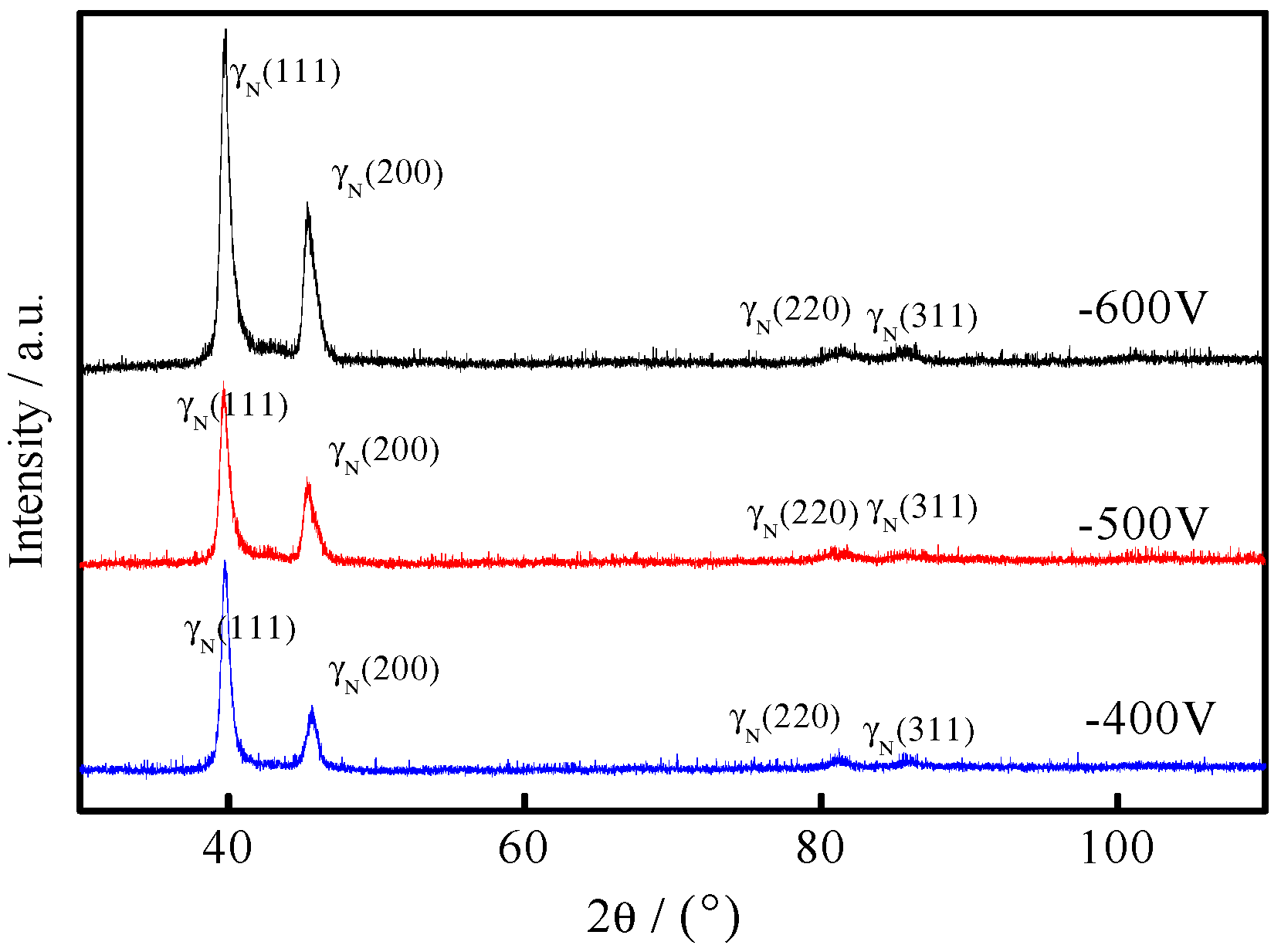
3.1. Phase Constitution of the Coating

Figure 1 showed XRD patterns of the 316L plasma-nitrided samples under different bias voltages. The XRD patterns of 316L stainless steel had the diffraction peaks of γ(111), γ(200), γ(220), γ(311), and γ(222). The diffraction peaks of γN(311) and γN(222) became wide after plasma nitriding, whereas the diffraction peak intensities of γN(111) and γN(200) increased. The diffraction peaks of all plasma-nitrided samples moved to the left and became asymmetric. The preferred orientations of the samples after plasma nitriding were still γN(111) and γN(200). Both the γN and γ phases in 316L stainless steel after plasma nitriding possessed a face-centered cubic structure. Interstitial N atoms entered the lattice interior and formed a supersaturated solid solution in austenite in 316L stainless steel [39]. The broadening of the diffraction peaks of γN(111) and γN(200) and the shift of all diffraction peaks to the left can be attributed to the occurrence of surface slips and the generation of the high stacking fault density in the crystal after plasma nitriding. With the increasing bias voltage, the bombardment energy increased, and the diffraction peaks of γN(111) and γN(200) tended to shift to a small angle. With the increasing energy, the surface of 316L stainless steel was activated, the matrix etching was increased, and the 316L passivation film was removed, thus increasing the diffusion of nitrogen atoms in austenite and causing the shift in the diffraction peaks. The diffraction peaks of CrN and Cr2N were not found in the XRD patterns, which indicated that no martensite and plasma-nitride precipitation appeared during low-temperature plasma nitriding. Therefore, the corrosion resistance of the plasma-nitrided coating became better.
Figure 2 shows the XRD patterns of the CrNx coating under different filament currents. With the increasing filament current, CrN grew along the CrN(111) and CrN(200) directions. The diffraction peaks of Cr2N(111), CrN(200), and Cr(110) appeared when the filament current was 3 A and the value of 2θ was between 40° and 45°. With the increasing filament current, the intensity of the Cr(110) diffraction peak decreased, and the Cr2N(111) diffraction peak changed to CrN(200). When the filament current was 5 A and the value of 2θ was between 60° and 65°, the diffraction peaks of Cr and CrN appeared. The diffraction peak of Cr2N(211) first increased and was then transformed to the CrN(220) peak. In comparison to the standard card peak positions, some diffraction peaks deviated slightly from the Bragg angle, so it proved that the lattice distortion was small, and the grain integrity was high.
The Rietveld whole pattern fitting was allowed to estimate the lattice parameters and the average crystallite size of the powders (Table 2) [40]. Rietveld evaluations should be considered only as estimations, as the fitting results were not completely satisfactory, irrespective of the efforts dedicated to this specific task. For the plasma-nitrided coating, the quantitative assessments suggested that the a-lattice parameter and b-lattice parameter (a = 6.9623–6.97597 Å, b = 6.9623–6.97597 Å) and the average crystallite size remained virtually constant (41.63–41.98 nm), while the c-lattice parameter was only slightly increased in the case of the voltage of −500 V. For the CrNx coating, when the filament current was 4 A, the quantitative assessments suggested that the c-lattice parameter (c = 4.56199–4.5841 Å) remained virtually constant, while the a-lattice parameter, b-lattice parameter (a = 4.58119–4.8113 Å, b = 4.58119–4.8113 Å), and the average crystallite size (8.94–9.61 nm) was slightly increased.

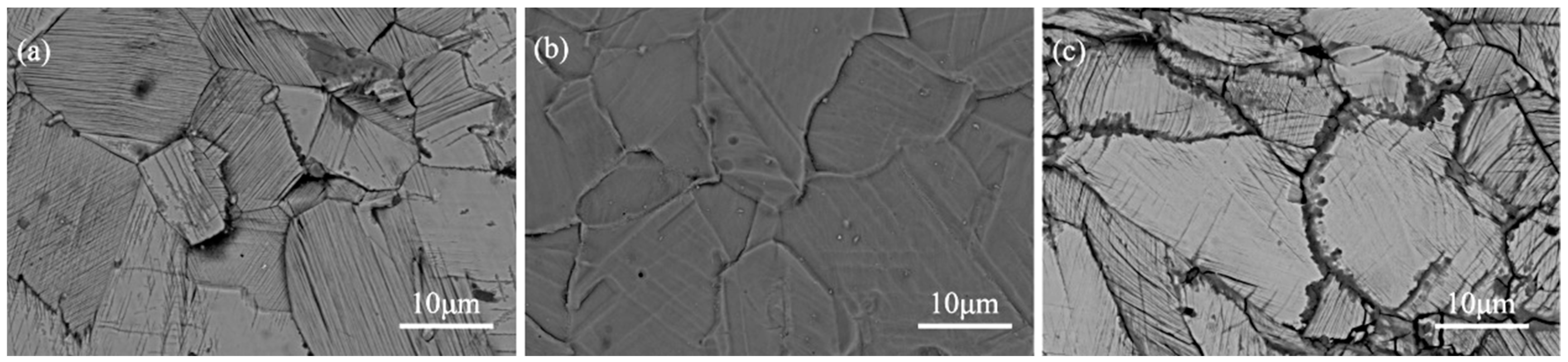
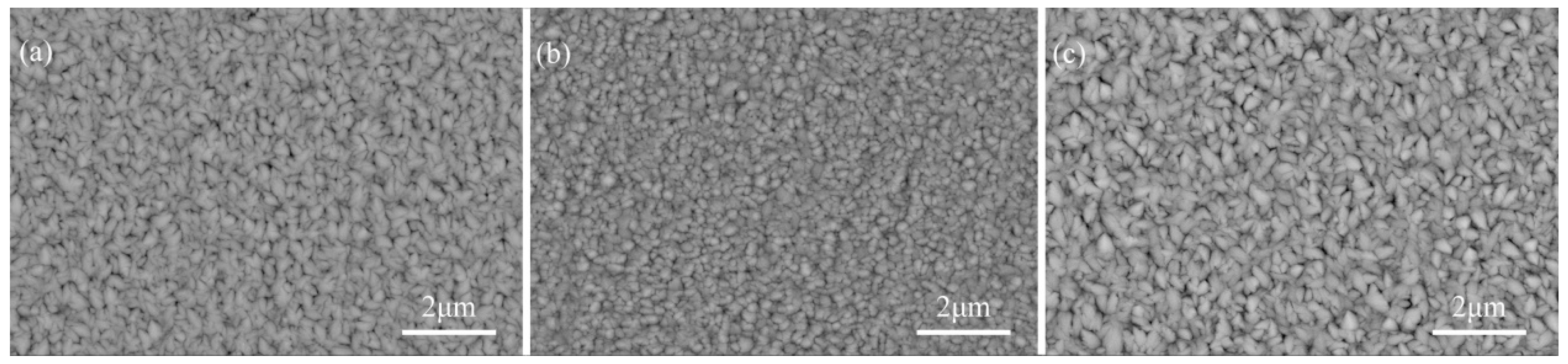
3.2. Morphology of the Coating

Figure 3 showed the surface morphologies of the plasma-nitrided coating under different bias voltages and expressed that twin diffraction peaks presented in the plasma-nitrided coating. With the increasing bias voltage, the amount of surface “cross grains” increased and the grain boundary became prominent with a small number of twins. The ion energy and the bombardment degree increased with the increasing bias voltage. The main features of the plasma-nitrided coating surface were its sharp grain boundary, large area of sliding, and large number of “moving steps.” The sharp grain boundary might occur due to the selective sputtering of nitrogen during the sputtering process. In addition, the anisotropy of the material was observed when nitrogen caused an expansion in the austenite crystal. The slip occurred due to the surface deformation caused by the anisotropic lattice expansion in the plasma-nitrided coating. When the bias voltage was −500 V, the surface of the sample was uniform and had some non-obvious grain boundaries and less striation due to the strong etching of excessive sputtering. Ion sputtering acts like an invisible knife and can peel off the surface molecules of a sample. When the plasma-nitriding bias voltage was −500 V, the energy and density of nitrogen in the cavity increased simultaneously due to ion sputtering. In comparison, when the bias voltage was −400 V, the mild ion sputtering selectively etched grain boundaries, which caused the samples rough surfaces. When the bias voltage was −600 V, defects appeared at grain boundaries due to the significant increase in substance energy. Moreover, a large anisotropic lattice distortion of nitrogen substances was observed in the plasma-nitrided coating.
Figure 4 showed surface morphologies of CrNx coating under different filament currents. As could be seen in Figure 4, the surface of the CrNx coating, produced by magnetron sputtering, was homogeneous, devoid of variations, being covered evenly with grains, as could be seen in Figure 4. The grains that cover the surface were arranged regularly without voids, forming a compact film. In Figure 4, it can clearly be seen that these coating grains were formed of particles with micrometer dimensions. It was indicated in Figure 4 that grains on the CrNx coating were in the form of long strips. With the increasing filament current, long grains gradually changed into cellular ones and less space existed between them. However, when the filament current was 5 A, the gap between grains again became large, and the amount of strip-shaped grains increased significantly. The increase in the filament current raised the surface temperature of grains, increased the bombardment energy of particles, increased the sputtering speed of Cr particles, increased the nucleation rate of Cr particles, and refined the grains. N particles filled the gap at the grain boundary and prevented F, SO42− and other ions in the electrolyte from the invading CrNx coating. However, when the current density of the filament was too high, the bombardment energy to the target increased, so the sputtering speed was too fast. The deposition of Cr particles was homogeneous, and N particles could not fill grain boundary pores, so corrosive substances in the electrolyte entered the inner part of the coating through grain boundary pores and caused a reduction in corrosion resistance.
Figure 3 showed that there were defects at the grain boundary of the plasma-nitrided coating and the surface of the plasma-nitrided coating is rough. Compared with the plasma-nitrided coating, the CrNx coating was more uniform and tiny. No pits or corrosion deposits are observed in the CrNx coating.

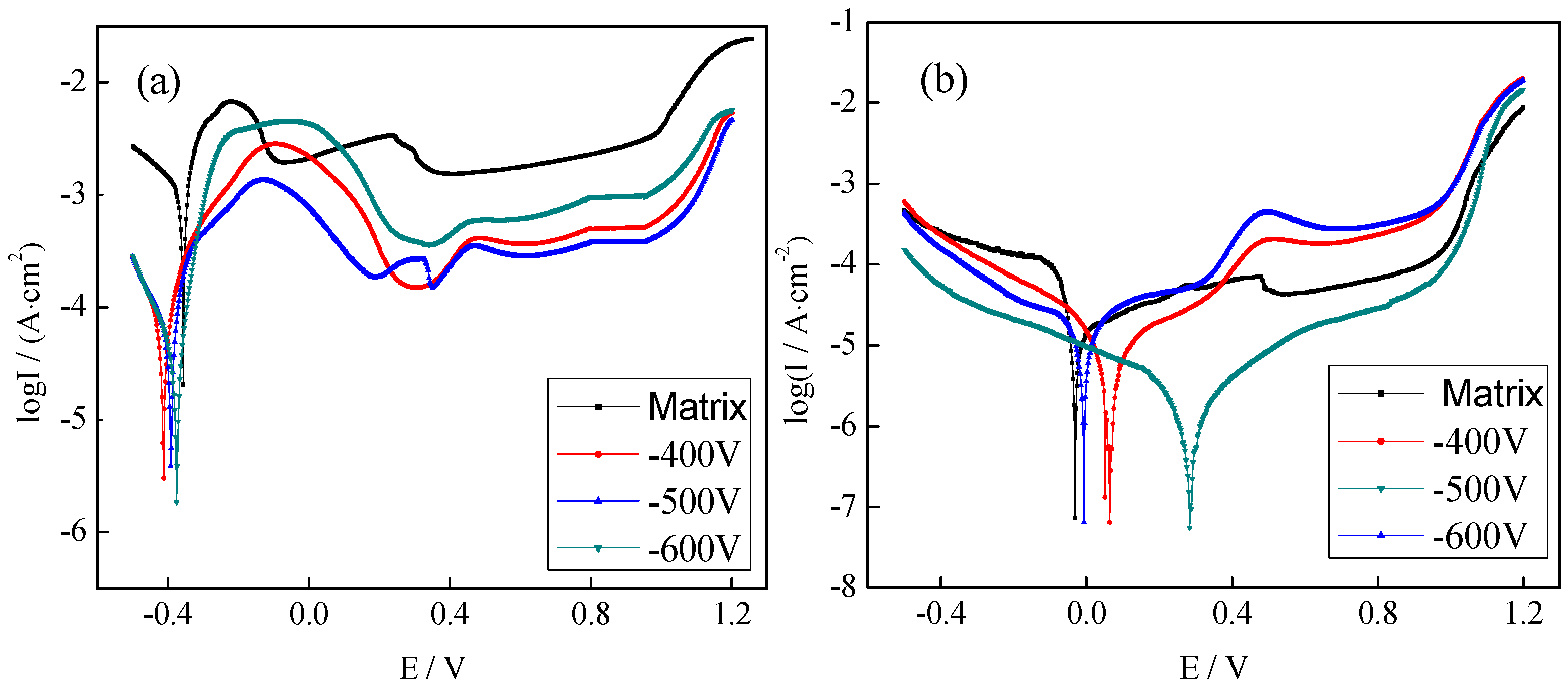
3.3. Electrochemical Measurements

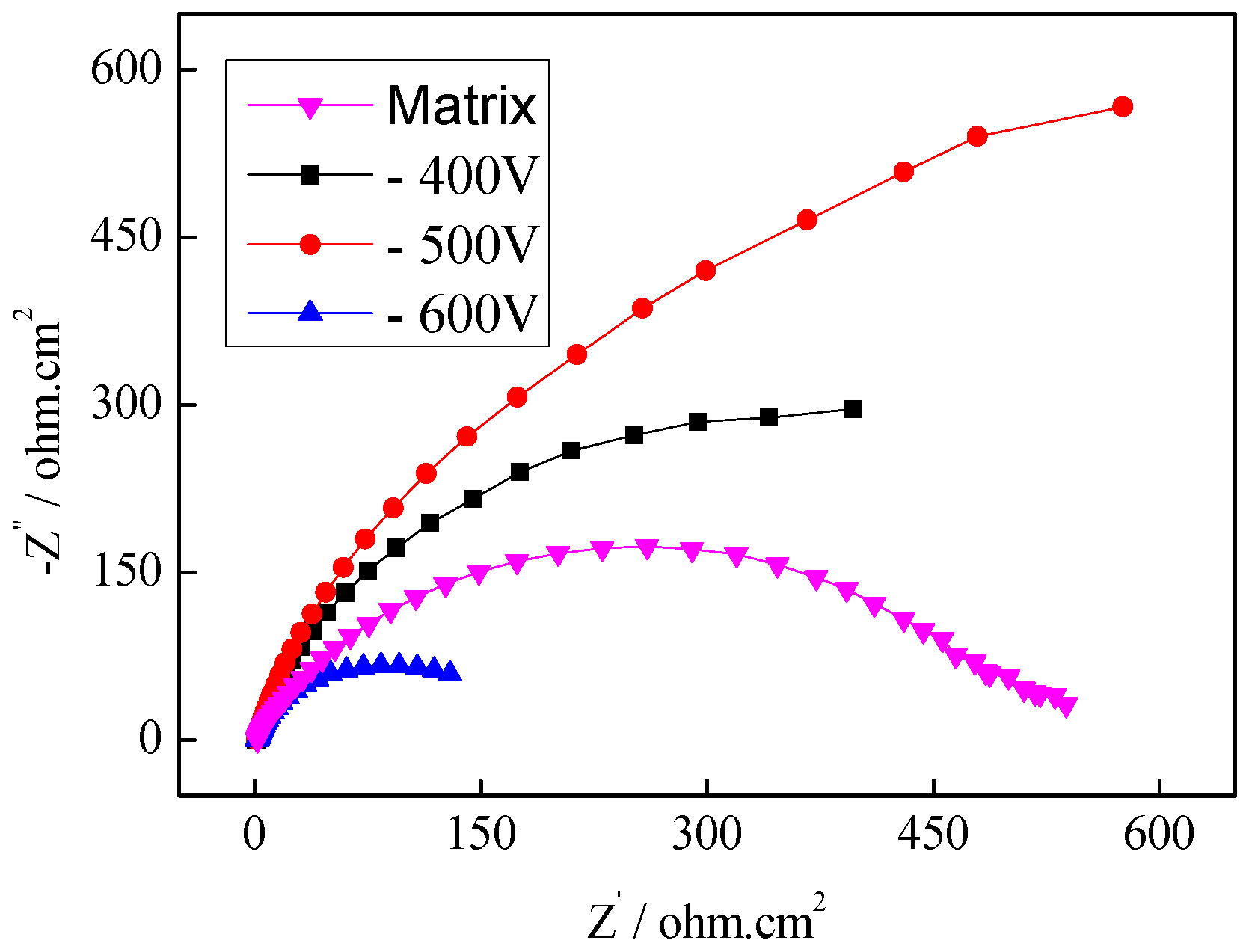
3.3.1. Electrochemical Measurements of the Plasma-Nitrided Coating

Figure 5 showed potentiodynamic polarization curves of the plasma-nitrided coating in the working environment of the PEMFC bipolar plate. The plotted curves consisted of an activated solution region, an activated passivation region, a passivation region, and an over passivation region after the plasma-nitriding treatment [41]. The range of the activation passivation zone of the sample increased significantly after plasma nitriding because the cathode potential was lower than the corrosion potential of the metal when air was purged into the simulated working environment of the PEMFC cathode and a passivation layer was easily formed on the metal surface. This process mainly occurred in the activation passivation region, so the curve range of the activation passivation region became larger. At the same Ecorr, the Icorr of the matrix was the smallest. When the bias voltage was −500 V, the corrosion current density of the plasma-nitrided coating was the smallest (0.907 μA·cm−2).
In the simulated working environment of the PEMFC anode, the range of the active solution area of the potentiodynamic polarization curves was very large and the active–passive area almost disappeared after plasma nitriding. The reason was most of hydrogen dissolved in the electrolyte of simulated anodic environment. H+ in the solution reacted with nitrogen in the plasma-nitrided coating and promoted the adsorption of H2 on the anode and accelerated the corrosion reaction. In addition, metal elements became ions after being dissolved in the anode and got attached to the catalyst surface to reduce their activity, so the active dissolution region became longer. In the anodic environment, with the increasing matrix bias voltage, the corrosion current density of the plasma-nitrided coating did not change significantly. The corrosion potential had a positive shift that increased first and then decreased. When the bias voltage was −500 V, the Ecorr of the plasma-nitrided coating attained the largest value of 0.307 V, and the Icorr value was 5.215 μA·cm−2.
Figure 6 showed the Nyquist curves of 316L stainless steel in the selected bias voltage range. Each impedance arc was composed of only one capacitive reactance arc in the high-frequency region. As the diameter of the capacitive arc and the Rt value on the electrode surface are related to metal dissolution, the corrosion resistance of a material gets improved for a larger capacitive arc. The diameter of the capacitive arc was the largest when the bias voltage was −500 V, so the corrosion resistance of the coating was better.

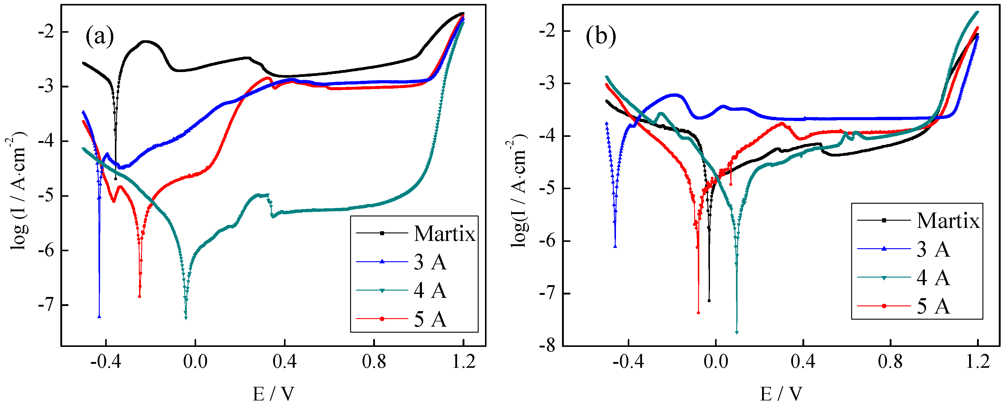
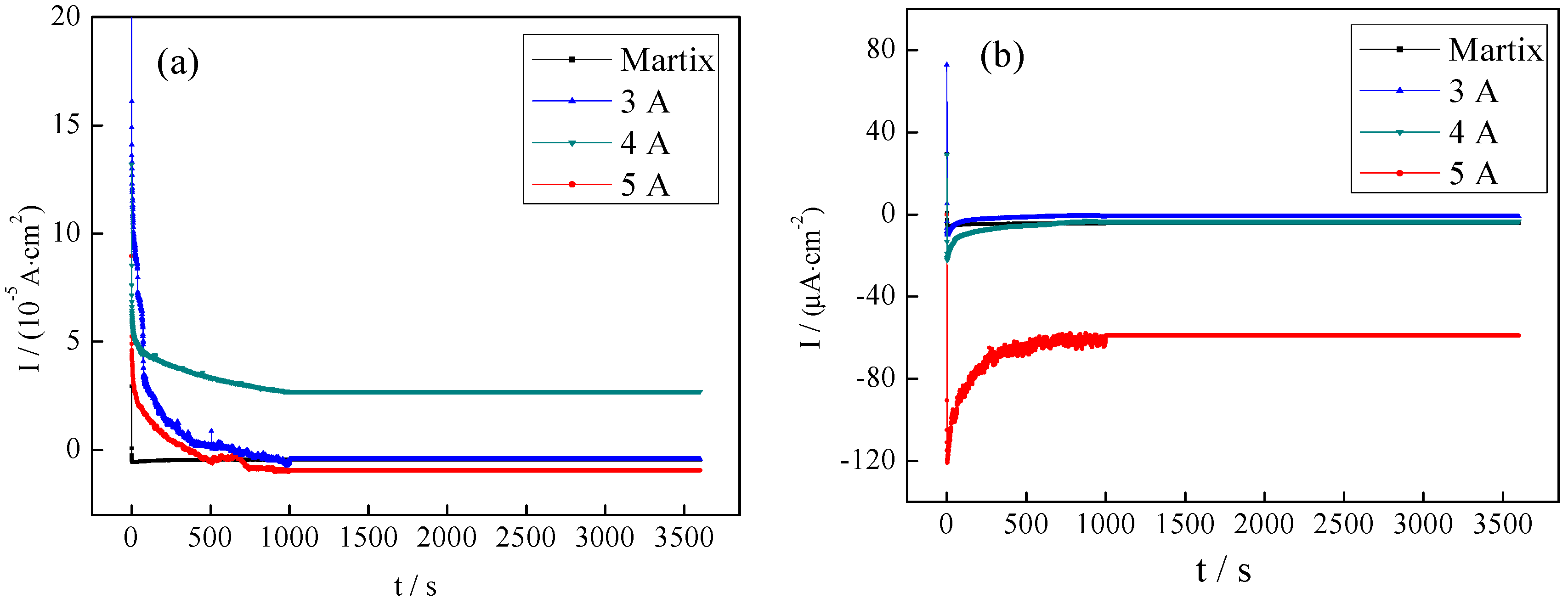
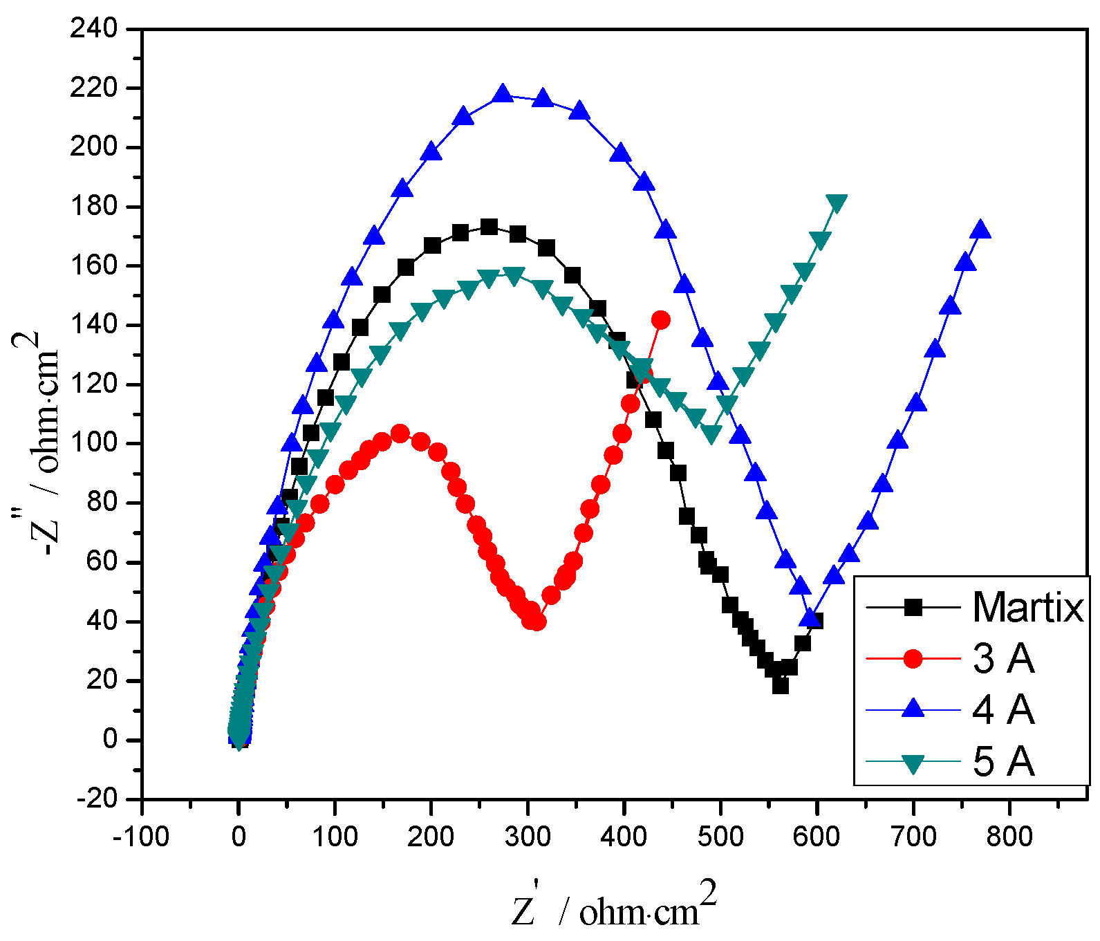
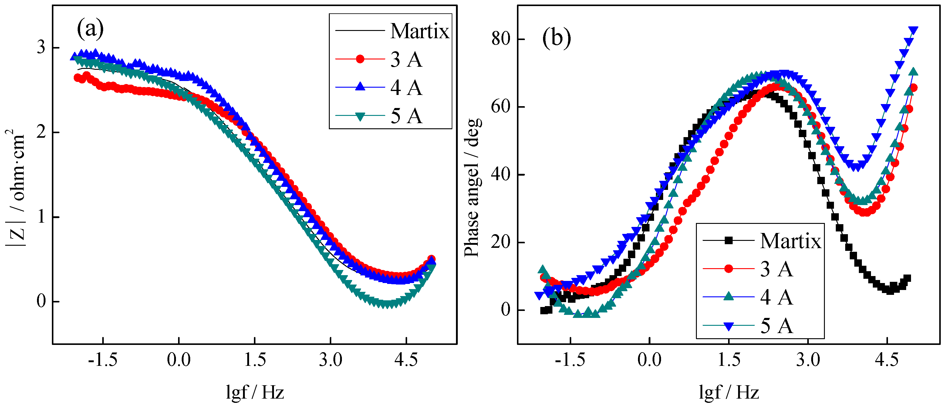
3.3.2. Electrochemical Measurements of the CrNx Coating

Th effect of manufacturing conditions on the corrosion resistance of 316L was discussed in another study by authors earlier [42]. Ma et al. studied even few ppm (5–10) of metal ions can poison the membrane of PEM-type fuel cell [43]. So, the research on the corrosion resistance of the CrNx coating is very important. Figure 7 showed Potentiodynamic polarization curves of the CrNx coating in the working environment of the PEMFC bipolar plate. The passivation range of the potentiodynamic polarization curve of the CrNx coating was similar to that of the matrix, but the corrosion current density was greatly reduced. Figure 7a showed potentiodynamic polarization curves in the cathodic working environment. When the filament current values were 3, 4, and 5 A, the active dissolving area increased and was larger than that of the matrix. However, the CrNx coating entered a stable passivation area after passing through the extremely narrow activation passivation area and indicated that the CrNx coating could self-passivate in the solution. The best corrosion resistance of the coating was obtained when the filament current was 4 A (Ecorr = −0.043 V, Icorr = 0.321 μA·cm−2).
Figure 7b showed potentiodynamic polarization curves in the anodic working environment. The activated solution area of the coated sample increased greatly, and the activated passivation area was very short, the corrosion current density was reduced, and the corrosion potential almost moved forward. With the increasing filament current, the active dissolving region first increased and then decreased gradually. Mobile nitrogen particles reacted with H+ in the electrolyte promoted the adsorption of H2 on the anode and accelerated the corrosion reaction. When nitrogen elements in the sample were exhausted, the corrosion current density decreased greatly, and the phenomena of metal dissolution and oxidation occurred, so the unstable activation passivation region almost disappeared. With the increasing filament current, the corrosion current density of the CrNx coating decreased first and then increased. When the filament current was 4 A, the corrosion current density of the CrNx coating was the lowest (1.881 μA·cm−2), the corrosion current density was the most positive. The corrosion current density was the smallest under a filament current density of 5 A because the lattice distortion increased and the preferred orientation changed greatly with the increasing filament current. The transition from CrN(200) to CrN(100) resulted in the change in the composition of the potentiodynamic polarization curve. Nitrogen elements made the metal passivate rapidly, so a fluctuation between the activation passivation region and the stable passivation region occurred and the stable passivation region was wider than those of other curves when the filament current was 5 A.
When the temperature is 80 °C, 99.999% hydrogen and air were purged into the electrolyte to simulate the anodic and cathodic environments of the PEMFC bipolar plate. Figure 8a shows potentiostatic polarization curves in the cathodic working environment. In the first minute, the current first decreased greatly and then became stable. The current densities of the coated samples were lower than that of the 316L stainless steel matrix, and the difference of corrosion current was not significant. When the filament current was 4 A, the corrosion current was smallest (4.136 μA). Figure 8b shows the potentiostatic polarization curve in the anodic working environment. In the first two minutes, the current decreased significantly and then tended to be stable. When the current was stable, the current density of the constant potential polarization curve at the filament current of 4 A was smallest (−3.534 μA). No obvious changes were observed on sample surfaces before and after the test, and the deposited CrNx coating had high stability.
Figure 9 shows an EIS analysis of CrNx coating under filament currents. Figure 9 illustrates that the trend of impedance diagrams of different filament current densities was the same. All curves were composed of a semicircle of the high frequency part and a linear function curve of the low frequency part. However, the curves of semicircles were not standard semicircles, but slightly expanded semicircles. From the linear part, the slopes of these linear functions were all positive numbers. When changing the filament current density, the gradient of the linear part in the Nyquist curve of the sample was the same, and the angle between the linear part and the horizontal axis in the figure was about 60°, which showed that changing the filament current density was not change the control steps and mechanism of the electrochemical reflection of the coating. Based on the Warburg impedance characteristics and coating performance analysis, it was speculated that the electrochemical corrosion of the matrix is relatively severe. In the later stage of corrosion, the surface CrNx coating and the bubble area at the CrNx interface had a larger porosity and the Cr layer was corroded. Brady et al. [44] showed that the diffusion process of the surface was equivalent to the spherical diffusion, resulting in the gradient value of the linear part greater than 1.
It was indicated from Figure 9 that the semicircle diameter on the Nyquist diagram was the largest when the filament current density was 4 A. When the current density was too small, the bombarding energy was small, the number of deposited particles was less, and the distribution of CrN on the coating surface was uniform. However, the final sample first reacted with the CrN coating and then with the Cr layer. The CrN coating had low density and possessed numerous pores, so corrosive ions in the electrolyte easily entered the coating to cause intergranular corrosion. Liu et al. [45] showed that the sputtering speed affected the adhesion of N and Cr particles. However, when the current density was too high, the target energy was also too high, and the sputtering speed of Cr particles was too fast and N particles could not fill grain boundary pores, so corrosive substances in the electrolyte entered the coating through grain boundary pores to cause corrosion.
Figure 10 showed the Bode curves of CrNx coating under different filament currents. All curves in the impedance frequency diagram (Figure 10a) and the phase-angle frequency diagram (Figure 10b) had a similar trend. When the filament current density was 4 A, the impedance mode value was the largest, and the corrosion resistance of the sample was better. In Figure 10b, the phase-angle frequency curve of the matrix has only one peak, whereas CrNx coating has two peaks (representing two time constants). When the filament current density was 4 A, the phase angle was the largest, and the corrosion resistance of the coating (close to 70°) was better.
Figure 11 showed the equivalent analog circuit diagram of EIS under different filament currents. Table 3 showed the EIS equivalent circuit fitting results under different filament currents. All the results illustrated that when the filament current was 4 A, the CrNx coating had good corrosion resistance.

3.3.3. Corrosion Resistance of Coatings

The plasma-nitrided coating and CrNx coating performed good corrosion resistance when the bias voltage was −500 V and the filament current was 4 A. In the Potentiodynamic polarization test, the corrosion current densities of the plasma-nitrided coating and CrNx coating were 0.907 and 0.312 μA·cm−2 in the cathodic environment and 5.215 and 1.881 μA·cm−2 in the anodic environment. So, the plasma-nitrided coating and CrNx coating had better corrosion resistance in the cathode environment than in the anode environment due to passivation of metals [46]. So, the corrosion resistance of the CrNx coating was better than the plasma-nitrided coating. It was indicated that the technology process of nitriding first and then depositing Cr was better than nitriding only.

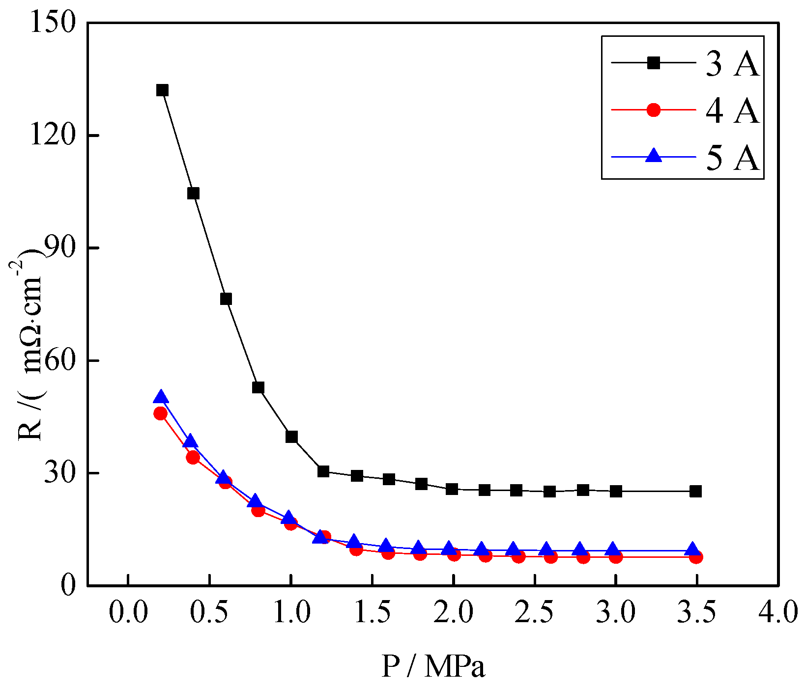
3.4. Contact Resistance of the CrNx Coating

Figure 12 shows the contact resistances of the CrNx coating under different filament currents. With the increase of the pressure per unit area, the contact resistance decreased sharply at the beginning and then changed smoothly and became stable at a pressure above 1.4 MPa. However, when the filament current was 3 A, the contact resistance was always much higher than those under other conditions. During the period of gentle change, the smallest contact resistance was obtained when the filament current was 4 A (7.64 mΩ·cm−2).
When 316L stainless steel was in the contact with air, thin films of iron oxide and chromium oxide were formed on its surface. These oxide films could not improve the corrosion resistance of stainless steel, but they increased the interface contact resistance. Wu et al. [47] showed that the compositions of these oxide films were greatly improved after plasma nitriding, so the corrosion resistance of the sample was also improved. When the filament current was 3 A, the coating was composed of CrN and Cr2N. However, when the filament current values were 4 and 5 A, Cr2N was completely converted into CrN. It was speculated that the difference in contact resistance at different filament currents occurred from different plasma-nitrided structures.

4. Conclusions

316L stainless steel surfaces were coated by the plasma-enhanced balanced magnetron sputtering. The XRD patterns indicated the presence of Cr, CrN, and Cr2N in the CrNx coating. The Rietveld whole pattern fitting was allowed to estimate the lattice parameters, the results showed that the average crystallite size of CrNx coating were better. The microstructures indicated that there were defects at the grain boundary of the plasma-nitrided coating and that the surface of the plasma-nitrided coating was rough. Compared with the plasma-nitrided coating, the CrNx coating was more uniform and denser. In the Potentiodynamic polarization test, the corrosion current densities of the plasma-nitrided coating and the CrNx coating were 0.907 and 0.312 μA·cm−2 in the cathodic environment and 5.215 and 1.881 μA·cm−2 in the anodic environment. A stable corrosion current density was obtained for coatings in Potentiostatic polarization test during 17 h. According to the corrosion tests results, the corrosion resistance of CrNx coating was better than the plasma-nitrided coating. It was indicated that the technology process of nitriding first and then depositing Cr was better than nitriding only. The CrNx-coated 316L stainless steel under a 4 A filament current possessed a lower ICR value than that of others in the range of the measured compaction force. Based on the results presented above, the CrNx coating on the 316L stainless steel can be acted as a promising bipolar plate material for application in PEMFC.

Author Contributions

Conceptualization, S.K. and M.X.; methodology, X.Y.; software, M.X.; validation, Z.W., T.C. and X.Y.; formal analysis, M.X.; investigation, T.C.; resources, J.L.; data curation, X.Y.; writing—original draft preparation, M.X.; writing—review and editing, Z.W.; visualization, T.C.; supervision, X.Y.; project administration, J.L.; funding acquisition, S.K. All authors have read and agreed to the published version of the manuscript.

Funding

This research received no external funding.

Acknowledgments

Authors are thankful to the supported by Liaoning Provincial Department of Education support.

Conflicts of Interest

The authors declare no conflict of interest.

Abbreviations

PEMFCProton exchange membrane fuel cell
EISElectrochemical impedance spectroscopy
CHPCombined heat and power
PVD Physical vapor deposition
CVD Chemical vapor deposition
SEMScanning electron microscope
ICRInterfacial contact resistance
WEWorking electrode
CECounter electrode
REReference electrode
EDSEnergy dispersive spectrometer
γN Austenite phase formed by nitrogen atom penetrating into matrix
γAustenite phase
θIncidence angle
Ecorr/μA·cm−2Corrosion potential
Icorr/μA·cm−2Current density
CrChromium
CrNxChromium nitride
H2 Hydrogen gas
O2 Oxygen gas
N2Nitrogen gas
ArArgon gas
RtCharge transfer resistance

References

  1. Mousa, G.; Golnaraghi, F.; DeVaal, J.; Young, A. Detecting proton exchange membrane fuel cell hydrogen leak using electrochemical impedance spectroscopy method. J. Power Sources 2014, 246, 110–116. [Google Scholar] [CrossRef]
  2. Holloway, L. One step solution for fifighting bacteria and growing bone. Sci. Transl. Med. 2019, 11, 5326. [Google Scholar] [CrossRef]
  3. Hu, L.; Cui, Y. Energy and environmental nanotechnology in conductive paper and textiles. Sci. Energy Environ. 2012, 5, 6423–6435. [Google Scholar] [CrossRef]
  4. Dastjerdi, R.; Montazer, M. A review on the application of inorganic nano-structured materials in the modifification of textiles: Focus on anti-microbial properties. J. Colloids Surf. Biointerfaces 2010, 79, 5–18. [Google Scholar] [CrossRef]
  5. Carmo, M.; Fritz, L.; Mergel, J. A comprehensive review on PEMFC water electrolysis. Sci. Hydrog. Energy 2013, 38, 4901–4934. [Google Scholar] [CrossRef]
  6. Taherian, R. A review of composite and metallic bipolar plates in proton exchange membrane fuel cell: Materials, fabrication, and material selection. Sci. Power Sources 2014, 265, 370–390. [Google Scholar] [CrossRef]
  7. Stenzel, O. The Physics of Thin Film Optical Spectra: An Introduction; Springer: Berlin, Germany, 2016. [Google Scholar]
  8. Bayrak, G.; Yilmaz, S. Crystallization kinetics of plasma-sprayed basalt coatings. J. Ceram. Int. 2006, 32, 441–446. [Google Scholar] [CrossRef]
  9. Wang, L.; Sun, J.; Li, P.; Jing, B.; Li, S.; Wen, Z.; Ji, S. Niobized AISI 304 stainless steel bipolar plate for proton exchange membrane fuel cell. Sci. Power Sources 2012, 208, 397–403. [Google Scholar] [CrossRef]
  10. Ctibor, P.; Nevrlá, B.; Pala, Z.; Sedlácek, J.; Soumar, J.; Kubatík, T.; Neufuss, K.; Vilémová, M.; Medˇrický, J. Study on the plasma-sprayed amorphous diopside and annealed fine-grained crystalline diopside. J. Ceram. Int. 2015, 41, 10578–10586. [Google Scholar] [CrossRef]
  11. Ctibor, P.; Neufuss, K.; Pala, Z.; Kotlan, J.; Soumar, J. Dielectric and mechanical properties of plasma-sprayed olivine. J. Rom. Rep. Phys. 2015, 67, 600–616. [Google Scholar]
  12. Samadi, H.; Pershin, L.; Coyle, T.W. Effect of in-flight particle properties on deposition of air plasma-sprayed forsterite. Sci. Surf. Coating. 2010, 204, 3300–3306. [Google Scholar] [CrossRef]
  13. Xu, T.; He, X.; Chen, Z.; He, L.; Lu, M.; Ge, J.; Weng, J.; Mu, Y.; Duan, K. Effect of magnesium particle fraction on osteoinduction of hydroxyapatite sphere-based scaffolds. Sci. Mater. Chem. B 2019, 7, 5648–5660. [Google Scholar] [CrossRef] [PubMed]
  14. Su, Y.; Wang, W.; He, Q. Research and development status of plasma physical vapor deposition equipment. J. Therm. Process. Technol. 2018, 22, 21–26. (In Chinese) [Google Scholar] [CrossRef]
  15. Bigi, A.; Falini, G.; Foresti, E.; Ripamonti, A.; Gazzano, M.; Roveri, N. Magnesium influence on hydroxyapatite crystallization. J. Inorg. Biochem. 1993, 49, 69–78. [Google Scholar] [CrossRef]
  16. Deng, Z.; Liu, M.; Mao, J.; Zhang, X.; Chen, W.; Chen, Z. Deposition mechanism based on plasma spray-physical vapor deposition. J. Inorg. Mater. 2017, 32, 1285–1291. (In Chinese) [Google Scholar] [CrossRef]
  17. Choi, I.S.; Park, J.C. The corrosion behavior of TiAlN coatings prepared by PVD in a hydrofluoric gas atmosphere. Sci. Surf. Coat. 2000, 131, 383–385. [Google Scholar] [CrossRef]
  18. Popa, A.; Stan, G.; Husanu, A.; Pasuk, I.; Popescu, I.; Popescu, A.; Mihailescu, I. Multi-layer haemocompatible diamond-like carbon coatings obtained by combined radio frequency plasma enhanced chemical vapor deposition and magnetron sputtering. Sci. Mater. 2013, 24, 2695–2707. [Google Scholar] [CrossRef]
  19. Li, Y.; Xu, H.; Qiu, J.; Xu, J.; Wang, L. Plasma nitrided technology of AISI 316L austenitic stainless steel hollow cathode discharge ion source. J. China Surf. Eng. 2014, 27, 25–30. (In Chinese) [Google Scholar] [CrossRef]
  20. Guo, Y.; Teng, Y.; Gao, J.; Zhang, X.; Huang, X.; Xie, Z.; Zhou, Y. Effect of pulse bias on surface structure and tribological properties of low temperature plasma nitrided stainless steel. J. Vac. Sci. Technol. 2017, 37, 902–908. (In Chinese) [Google Scholar] [CrossRef]
  21. Ji, C.; Shi, H.; Cui, X. Study on Microstructure and Properties of Duplex Stainless Steel Formed by Surface Nitridation of SUS430. J. Therm. Process Technol. 2017, 46, 179–181. (In Chinese) [Google Scholar] [CrossRef]
  22. Wang, J.; Sun, J.; Zhang, F. Performance of stainless steel bipolar plate after low temperature plasma nitrided. J. Mater. Prot. 2010, 43, 65–67. (In Chinese) [Google Scholar] [CrossRef]
  23. Pan, C.; Zhou, Z.; Yu, X. Coatings as the useful drug delivery system for the prevention of implant-related infections. Sci. Orthop. Surg. Res. 2018, 13, 1–11. [Google Scholar] [CrossRef] [PubMed] [Green Version]
  24. Nam, N.; Jo, D.; Kim, J.; Yoon, D. Corrosion protection of CrN/TiN multi-coating for bipolar plate of polymer electrolyte membrane fuel cell. J. Solid Films 2011, 519, 6787–6791. [Google Scholar] [CrossRef]
  25. Mani, S.; Srinivasan, A.; Rajendran, N. Effect of nitrides on the corrosion behaviour of 316L SS bipolar plates for proton exchange membrane fuel cell (PEMFC). Sci. Hydrog. Energy 2015, 40, 3359–3369. [Google Scholar] [CrossRef]
  26. Chen, S.; Yuan, L.; Li, Q.; Li, J.; Zhu, X.; Jiang, Y.; Sha, O.; Yang, X.; Xin, J.H.; Wang, J.; et al. Durable antibacterial and nonfouling cotton textiles with enhanced comfort via zwitterionic sulfopropylbetaine coating. Sci. Small. 2016, 12, 3516–3521. [Google Scholar] [CrossRef]
  27. Oladijo, O.P.; Mathabatha, M.H.; Ntsoane, T.P. Characterization and corrosion behaviour of plasma sprayed Zn–Sn alloy coating on mild steel. Sci. Surf. Coat. Technol. 2018, 352, 654–661. [Google Scholar] [CrossRef]
  28. Stan, G.E.; Marcov, D.A.; Pasuk, I.; Miculescu, F.; Pina, S.; Tulyaganov, D.U.; Ferreira, J.M.F. Bioactive glass thin films depositd by magnetron sputtering technique: The role of working pressure. Sci. Appl. Surf. 2010, 256, 7102–7110. [Google Scholar] [CrossRef]
  29. Stenzel, O.; Wilbrandt, S.; Kaiser, N.; Schmitz, C.; Turowski, M.; Ristau, D.; Awakowicz, P.; Brinkmann, R.P.; Musch, T.; Rolfes, I.; et al. Plasma and optical thin film technologies. J. Proc. SPIE 2011, 8168, 81680L. [Google Scholar]
  30. Evans, C.C.; Bradley, J.D.B.; Parsy, F.; Phillips, K.C.; Senaratne, R.; Martí-Panameño, E.A.; Mazur, E. Thermally Managed Z-Scan Measurements of Titanium Dioxide Thin Films; Photonics West: San Francisco, CA, USA, 2011. [Google Scholar]
  31. Zhang, M.; Lin, G.; Wu, B.; Shao, Z. Composition optimization of arc ion plated CrNx films on 316L stainless steel as bipolar plates for polymer electrolyte membrane fuel cells. Sci. Power Sources 2012, 205, 318–323. [Google Scholar] [CrossRef]
  32. Ageorges, H.; Medarhri, Z.; Ctibor, P.; Fauchais, P. Plasma-sprayed basalt/chromium oxide coatings. Sci. High Temp. Mater. 2007, 11, 71–81. [Google Scholar] [CrossRef]
  33. Han, C.; Mohanty, B.; Choi, H.; Cho, Y. Surface scaling evolution and dielectric properties of sputter-deposited low loss Mg2SiO4 thin films. Sci. Surf. Coat. 2013, 231, 229–233. [Google Scholar] [CrossRef]
  34. Xie, Y.; Zhai, W.; Chen, L.; Chang, J.; Zheng, X.; Ding, C. Preparation and in vitro evaluation of plasma-sprayed Mg2SiO4 coating on titanium alloy. J. Acta Biomater. 2009, 5, 2331–2337. [Google Scholar] [CrossRef]
  35. Xue, W.; Liu, X.; Zheng, X.; Ding, C. Plasma-sprayed diopside coatings for biomedical applications. Sci. Surf. Coat. 2004, 185, 340–345. [Google Scholar] [CrossRef]
  36. Salimijazi, H.; Hossejni, M.; Mostaghimi, J.; Pershin, L.; Coyle, T.; Samadi, H.; Shafyei, A. Plasma-sprayed coating using mullite and mixed alumina/silica powders. J. Spray Technol. 2012, 21, 825–830. [Google Scholar] [CrossRef]
  37. Ercenk, E.; Sen, U.; Yilmaz, S. Structural characterization of plasma-sprayed basalt–SiC glass–ceramic coatings. J. Ceram. Int. 2011, 37, 883–889. [Google Scholar] [CrossRef]
  38. Bouhifd, M.A.; Andrault, D.; Fiquet, G.; Richet, P. Thermal expansion of forsterite up to the melting point. Sci. Mater. 1996, 23, 1143–1146. [Google Scholar] [CrossRef]
  39. Fu, T.; Zhao, C.; Luo, H.; Zeng, Q.; Zhang, Y.; Liu, C. Structure and properties of 304 austenitic stainless steel by low temperature salt bath nitrocarburizing. J. Met. Heat Treat. 2011, 36, 98–101. (In Chinese) [Google Scholar] [CrossRef]
  40. Rietveld, H. A profile refinement method for nuclear and magnetic structures. J. Appl. Crystallogr. 1969, 2, 65–71. [Google Scholar] [CrossRef]
  41. Brady, M.P.; Weisbrod, K.; Paulauskas, I.; Buchanan, R.A.; More, K.L.; Wang, H.; Wilson, M.; Garzon, F.; Walker, L.R. Preferential thermal nitridation to form pinhole free Cr-nitrides to protect proton exchange membrane fuel cell metallic bipolar plates. Sci. Mater. 2004, 50, 1017–1022. [Google Scholar]
  42. Dundar, F.; Dur, E.; Mahabunphachai, S.; Koc, M. Corrosion resistance characteristics of stamped and hydroformed proton exchange membrane fuel cell metallic bipolar plates. Sci. J. Power Sources 2010, 195, 3546–3552. [Google Scholar] [CrossRef]
  43. Ma, L.; Warthesen, S.; Shores, D.A. Evaluation of materials for bipolar plates in PEMFCs. Sci. New Mater. Electrochem. 2000, 3, 221–228. [Google Scholar]
  44. Brady, M.P.; Wang, H.; Yang, B.; Turner, J.A.; Bordignon, M.; Molins, R.; Abd Elhamid, M.; Lipp, L.; Walker, L.R. Growth of Cr-nitrides on commercial Ni–Cr and Fe–Cr base alloys to protect PEMFC bipolar plates. Sci. Hydrog. Energy 2007, 32, 3778–3788. [Google Scholar] [CrossRef]
  45. Liu, J.; Chen, F.; Chen, Y.; Zhang, D. Plasma nitrided titanium as a bipolar plate for proton exchange membrane fuel cell. Sci. Power Sources 2009, 187, 500–504. [Google Scholar] [CrossRef]
  46. Tian, R. Chromium nitride/Cr coated 316L stainless steel as bipolar plate for proton exchange membrane fuel cell. Sci. Electrochem. Acta. 2011, 48, 1735–1741. [Google Scholar] [CrossRef]
  47. Wu, B.; Fu, Y.; Xu, J.; Lin, G.; Hou, M. Chromium nitride films on stainless steel as bipolar plate for proton exchange membrane fuel cell. Sci. Power Sources 2009, 194, 976–980. [Google Scholar] [CrossRef]
Figure 1. X-ray diffraction (XRD) patterns of the plasma-nitrided coating under different bias voltages.
Coatings 10 00183 g001
Figure 2. XRD patterns of the CrNx coating under different filament currents.
Coatings 10 00183 g002
Figure 3. Surface morphologies of the plasma-nitrided coating under different bias voltages: (a) −400 V, (b) −500 V, (c) −600 V.
Coatings 10 00183 g003
Figure 4. Surface morphologies of the CrNx coating under different filament currents: (a) 3 A, (b) 4 A, (c) 5 A.
Coatings 10 00183 g004
Figure 5. Potentiodynamic polarization curves of the plasma-nitrided coating in the working environment of the PEMFC bipolar plate ((a) cathodic working environment, (b) anodic working environment).
Coatings 10 00183 g005
Figure 6. Electrochemical impedance spectroscopy (EIS) analysis of the plasma-nitrided coating under different bias voltages.
Coatings 10 00183 g006
Figure 7. Potentiodynamic polarization curves of the CrNx coating in the working environment of the PEMFC bipolar plate ((a) cathodic working environment, (b) anodic working environment).
Coatings 10 00183 g007
Figure 8. Potentiostatic polarization curves of the CrNx coating in the working environment of the PEMFC bipolar plate ((a) cathodic working environment, (b) anodic working environment).
Coatings 10 00183 g008
Figure 9. EIS analysis of CrNx coating under different filament currents.
Coatings 10 00183 g009
Figure 10. Bode curves of the CrNx coating under different filament currents ((a) Impedance mode value (|Z|) versus frequency (f) curves, (b) Phase angle versus frequency (f) curves).
Coatings 10 00183 g010
Figure 11. Equivalent analog circuit diagram of EIS under different filament currents (Rs, Corrosion solution resistance; Rp, Corrosion product resistance of coating; Q1, Corrosion product capacitance of coating; Rt, Charge transfer resistance; Q2, Double layer capacitance; W, Warburg resistance).
Coatings 10 00183 g011
Figure 12. Contact resistances of the CrNx coating under different filament currents.
Coatings 10 00183 g012
Table 1. Chemical composition of 316L stainless steel.
ComponentCSiMnPCrNiMoFe
Content (%)≤0.08≤12–3≤0.03516–18.510–142–3balance
Table 2. Lattice parameters and average crystallite size for the plasma-nitrided coating and CrNx coating under different condition grains (as extracted by Rietveld whole pattern fitting).
Sample Tapea-Lattice Constant (Å)b-Lattice Constant (Å)c-Lattice Constant (Å)Average Crystallite Size (Å)
−400 V6.9623 ± 0.0066.9623 ± 0.0069.9381 ± 0.005417.20
−500 V6.97597 ± 0.0026.9759 ± 0.0029.96191 ± 0.004419.84
−600 V6.96761 ± 0.0156.9676 ± 0.0159.90159 ± 0.019416.30
3 A4.58119 ± 0.0014.5811 ± 0.0014.58119 ± 0.00189.89
4 A4.8113 ± 0.0024.8113 ± 0.0024.5841 ± 0.01596.15
5 A4.81079 ± 0.0074.8107 ± 0.0074.56199 ± 0.03389.40
Table 3. EIS equivalent circuit fitting results under different filament currents.
Filament Current/ARs/Ω·cm2Q1/μF·cm2n1Rp/Ω·cm2Q2/μF·cm2n2Rt/Ω·cm-2W/mΩ·cm2
Matrix1.858304.3504.3
3 A1.0000.76720.92752.63133.740.8735448.55.797
4 A2.6713.2720.8912169.739.510.9710114.69.831
5 A1.0331.0580.84282.08253.760.9665251.24.765

