Article

Preparation of WC Reinforced Co-Based Alloy Gradient Coatings on a H13 Mold Steel Substrate by Laser Cladding

School of Mechanical Engineering, University of Jinan, Jinan 250022, China
*
Author to whom correspondence should be addressed.
Coatings 2020, 10(2), 176; https://doi.org/10.3390/coatings10020176
Submission received: 3 January 2020 / Revised: 11 February 2020 / Accepted: 11 February 2020 / Published: 14 February 2020

Abstract

:
H13 die steel often fails as a result of physical and chemical effects such as wear, erosion and cyclic stress. Accordingly, the study evaluates Co-based gradient coating on an H13 steel featuring a stress-relieving effect. Scanning electron microscope and X-ray diffraction were used to analyze the microstructure and phase of the coatings. A microhardness tester and friction and wear tester were used to compare the hardness and wear resistance of the coatings and the substrate, and the wear morphology was observed. A pendulum impact test was used to compare the impact resistance of the coatings and the substrate, and the fracture morphology was observed. Finally, a corrosion test was used to compare the corrosion resistance of coatings and substrate. The results show that the Co-based gradient coatings have good combinations with the substrate, the hard phase content gradually increases from the bottom to the top of the coating, and the crystal microstructure generally maintains a distribution trend from coarse to fine. The hardness of the gradient coatings is significantly higher than the substrate, and from the coating surface to the substrate, the hardness decreases slowly. The wear loss of the coatings is much lower than that of the substrate, the main wear mechanism of the substrate is abrasive wear, and the main wear mechanism of the coatings is brittle spalling. While the gradient coatings increase the surface hardness, the brittleness also increases, the impact resistance of the coatings is lower than that of the substrate, the fracture form of the substrate is a ductile fracture, and the fracture form of the coating is a brittle fracture. The gradient coatings effectively improve the corrosion resistance of the substrate surface, and the higher the content of the reinforcing phase, the better the corrosion resistance of the coatings.

1. Introduction

H13 steel is an important hot working mold steel, also known as 4Cr5MoSiV1. It has high hardenability, hardness, good toughness, thermal fatigue resistance, heat resistance, thermal stability, oxidation resistance and corrosion resistance. It is widely used in the manufacture of various molds [1,2]. The development of the mold industry affects the manufacturing level of a country; despite the rapid development of China’s mold industry, the service life of mold steel is low, and the waste caused by the low service life of mold is about several hundred million yuan each year. Improving the life of the mold is a very urgent task and has become an increasingly prominent problem.
In the process of production and use, H13 hot work molds are constantly subjected to physical, chemical effects such as wear, thermal fatigue, erosion, stress corrosion, as well as the effects of cold and heat alternation and impact loads [3,4]. In such a harsh environment, molds are prone to thermal fatigue, thermal wear, and cracking [5]. As we all know, the failure of the mold starts most frequently on the surface [6]. In other words, improving the surface microstructure and performance can effectively increase the service life of the mold. Therefore, the necessary surface strengthening measures for hot work molds are an important means to improve the service life of molds.
Compared with other surface modification technologies, laser cladding technology has advantages not available in other methods. Not only can it obtain a coating with an ideal thickness, but also the metallurgical combination of the coating and the substrate has a high bonding strength, which can effectively improve the wear resistance and oxidation and corrosion resistance of the tool surface and has great application and development prospects [7]. In addition, the Stoney equation and some specific devices are proposed to be used in coatings characterization, which can detect and measure stresses on fine layers [8]. Present and future works must use these new ideas. The development of these theories and methods has further promoted the application of laser cladding technology.
Laser cladding materials mainly include self-fluxing alloy materials, ceramic materials, and composite materials [9]. Self-fluxing alloy refers to an alloy with iron, cobalt and nickel as the matrix, adding elements such as Si and B that have strong deoxidation and self-melting effects [10]. Ceramic powder mainly includes oxide ceramic powder and carbide ceramic powder. Oxide ceramic powders mainly include Al2O3, ZrO2, Cr2O3, TiO2, etc., which have good high temperature resistance, wear resistance, corrosion resistance and other properties. Carbide ceramic powders mainly include WC, TiC, SiC, Cr3C2, etc., which have high hardness and good abrasion resistance [11].
Due to development needs, people’s requirements for material properties are getting higher and higher. It is difficult for a single material coating to simultaneously meet the improvement of multiple aspects of the material, while composite materials can improve many properties of materials [12,13]. In order to further improve the properties of the coating, ceramic particles are added to the self-fluxing alloy powder. However, the addition of ceramic particles makes the thermal expansion coefficient and elastic modulus of the composite coating significantly different from that of the substrate. During the cladding process, thermal stress is caused by the huge performance difference between the coating and the substrate, which makes the combination of the coating and the substrate poor [14].
Therefore, gradient materials have become a key to solve the problem. In 1987, the Japanese Science and Technology Agency proposed “gradient functional materials” [15]. The design idea is to make the physical and chemical properties of coating gradually and continuously transition to avoid the abrupt change of performance from the substrate to the coating [16], alleviate the stress condition at the interface, improve the bonding condition between the coating interfaces so that the coating can obtain appropriate hardness, toughness and residual stress, so as to effectively inhibit the generation and expansion of cracks [17], improve the load-bearing capacity and anti-friction properties of the coating.
In order to improve the service life of H13 hot work steel, cobalt-based coatings with a gradient effect were prepared on the surface of the H13 steel substrate, and the performance of the coatings was measured by the experiments.

2. Experimental Materials and Methods

2.1. Material and Sample Preparation

H13 steel was supplied by the supplier and has been quenched and tempered, and the microstructure is tempered sorbite. The test piece was analyzed by EDS(Oxford Instruments, Shanghai, China), and its chemical composition is shown in Table 1.
Molybdenum, chromium and other elements improve the hardenability, fatigue resistance and oxidation resistance of H13 steel. Silicon improves the decarburization sensitivity of the steel. Vanadium strengthens the second hardening of the steel and improves the thermal stability of the steel [18].
Because of its excellent wear resistance, corrosion resistance and high temperature resistance, the Co-based ceramic reinforced composite coating has become a hot research topic of laser cladding surface modification. In this test, different contents of WC ceramic particles were added to Co-based self-fluxing alloy powder. The chemical composition of Co-based alloy powder is shown in Table 2, and the data was provided by the supplier. The purity of WC is 99.9%, and the particle size is 2.5–3.5 μm.
Before the laser cladding test, the surfaces of the substrates need to be conditioned. The surfaces of the substrates were polished from coarse to fine with different types of sandpaper to remove the surface oxide layer and oil stains. The polished samples were ultrasonically cleaned with absolute ethanol and put into a drying box for drying treatment.
The cladding powder used in this test was prepared by electronic balance. WC powder was added to the Co-based alloy powder at a mass fraction of 5%, 10%, 15%, 20%, and 25%. The prepared composite powders were separately placed into a planetary ball mill. The ball-to-material ratio was 10:1, and the ball milling time was 6 h, which made the composite powder mix evenly and refine the particles. Finally, the mixed powders were put into a drying box and dried at 100 °C.
The H13 steel substrates were preheated at a temperature of 200 °C to reduce the thermal stress caused by the excessive temperature difference between the substrate and the coating during cladding, thereby reducing cracks and ensuring the quality of the coating.
In this test, three samples with Co-based gradient coatings were prepared, each sample has three cladding layers, and the mass fraction of WC increases from bottom to top. The proportion of gradient coating composite powder is shown in Table 3.
In the process of laser cladding, several main parameters, such as defocusing amount, frequency, scanning speed, pulse width, single pulse energy and so on, were mainly considered to affect the performance of the cladding layer, and the optimal combination parameters were finally determined, as shown in Table 4.

2.2. Analysis Methods

The samples were cut into small pieces of 10 × 10 × 10 mm, sanded with 200–1500 abrasive paper, and then polished with diamond polishing agent. The cross section of the gradient coating was viewed with a scanning electron microscope (HITACHI, Tokyo, Japan) to evaluate the quality of the cladding.
Then, the samples were etched with aqua regia (HCl:HNO3 = 3:1). During the corrosion process, attention should be paid to the corrosion time. The microstructure of the gradient coatings were observed with a metallographic microscope (Shang Guang, Shanghai, China).
The 402MVD micro Vickers hardness tester was used to test the microhardness of the samples. The load was 100 g, and the loading time was 15 s. The hardness of the gradient coating section was measured every 0.2 mm from the coating surface to the substrate. Five points were measured at different positions of the same horizontal line each time, and the average value was taken.
The reciprocating friction and wear test was carried out with RTEC MFT-50 friction and wear tester. (Rtec, Nanjing, Jiangsu, China) The grinding specimen was a silicon nitride ceramic ball. The parameters set in the test were: test force 50 N, reciprocating stroke 10 mm, reciprocating frequency 30 Hz, wear time 1800 s, test temperature 17 °C humidity 50%. The weight loss of the samples was measured by an analytical balance with an accuracy of 0.0001 g, and the wear morphology was observed with a scanning electron microscope.
The impact test was carried out according to GB/T229-2007 “Metal Charpy Notched Impact Test Method”. The size of the impact specimens is 10 × 10 × 55 mm. The V-notch is processed in the middle of the impact surface of the substrate, the angle is 45°, the depth is 2 mm, and the radius of curvature at the bottom is 0.25 mm. The impact test equipment was a JBN-300C microcomputer-controlled pendulum impact test machine (Ji’nan Shijin Group Co. Ltd., Jinan, Shandong, China), and the test temperature was 17 °C. The schematic diagram of the impact test is shown in Figure 1.
The static corrosion method was used to test the corrosion performance of the samples. The four sides and the bottom of the samples were sealed with RTV silicone rubber, only the coating to be corroded was exposed. Then, the samples were put into the self-made corrosion solution, the ratio of nitric acid and hydrochloric acid was 1:1, and the concentration was 15%. The different samples were respectively immersed in the corrosion solution for 24 h, and then they were taken out and put into anhydrous ethanol for ultrasonic cleaning and drying. The weight loss before and after the corrosion test was compared, and the morphology after corrosion was observed.

3. Results and Discussion

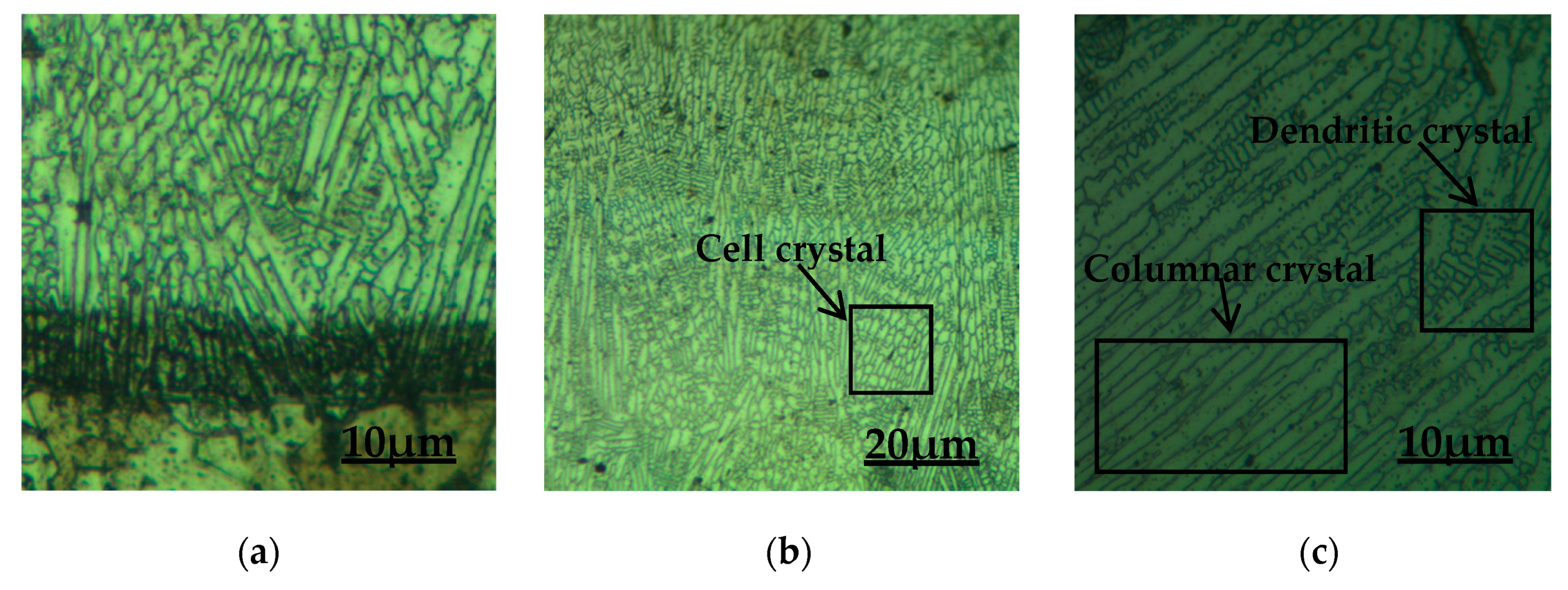
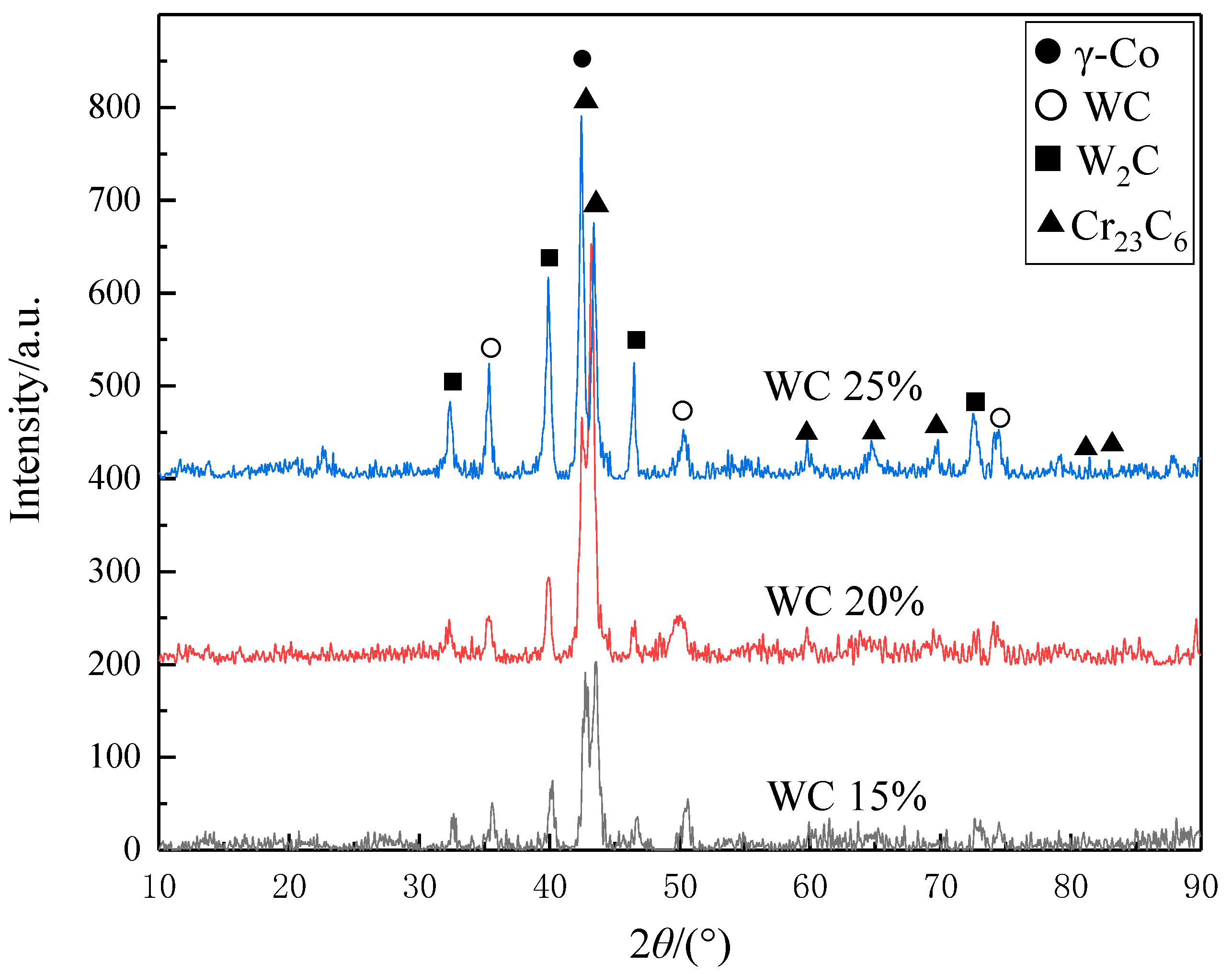
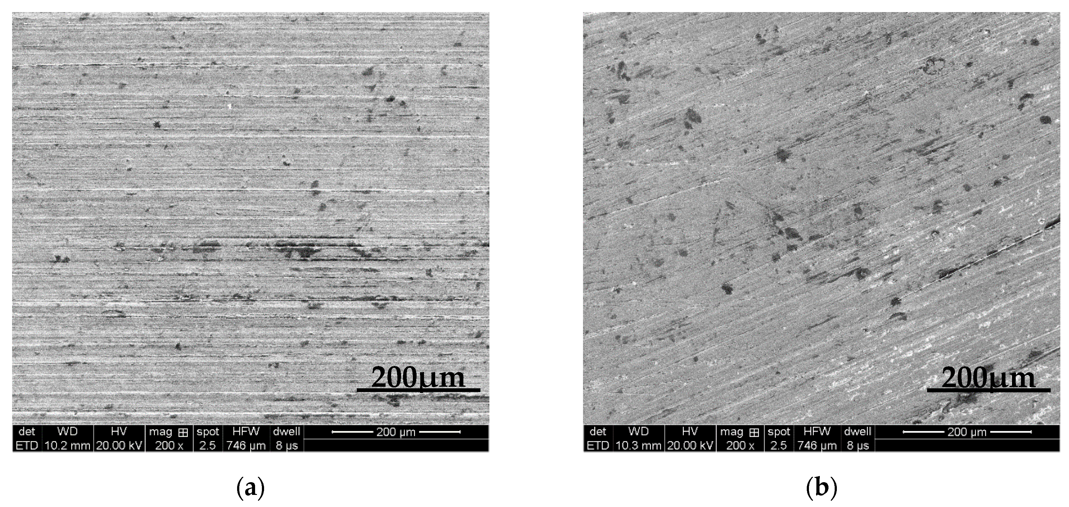
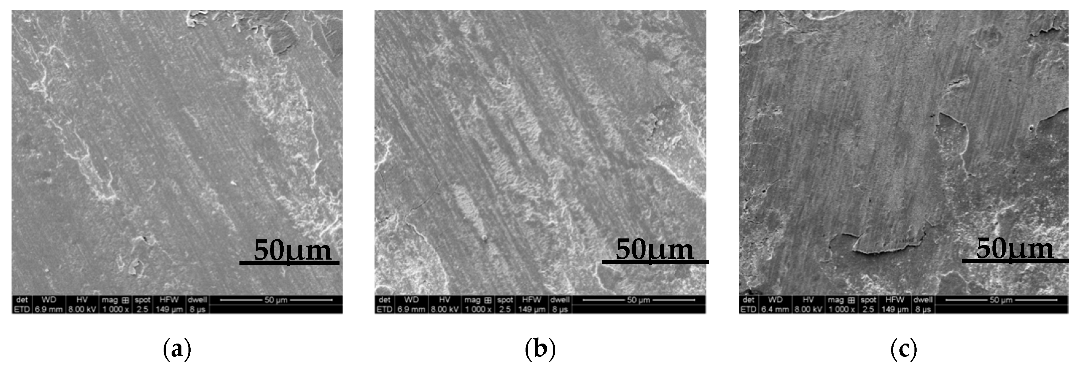
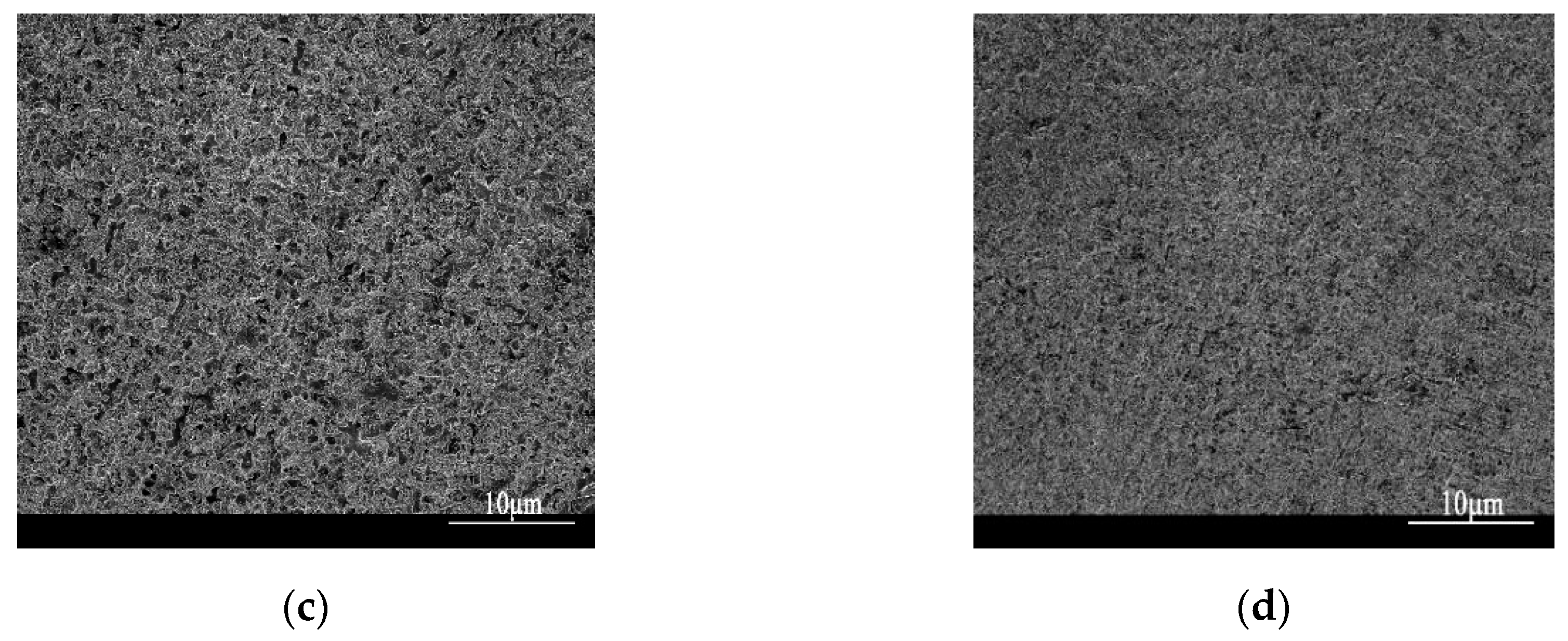
3.1. Morphology and Microstructure

The following figures show the combination of the coating and the substrate of the first sample.
It can be seen from Figure 2 that there are almost no defects in the whole coating, the bonding interface between the coating and the substrate is relatively straight, and the bonding zone is a relatively smooth curve. It can be seen that the dilution rate of the coating on the substrate is very small, the bonding condition between the coating and the substrate is good, there are no obvious cracks in the coating, and the coating forms a good metallurgical bond with the base steel. The general change trend of the gradient coating microstructure from bottom to top is that the number of white strengthening phases dispersed in the gradient coating gradually increases, while the content of the γ-Co matrix phase gradually decreases. Due to the increase of WC content in the coating from bottom to top, the carbide and other strengthening phases will increase gradually, while the decrease of Co content and the inhibition of carbide and other strengthening phases on the growth of the γ-Co matrix phase will lead to the decrease of the γ-Co matrix phase.
Because of the phenomenon of repeated heating in the gradient coating, the phenomenon of heat convection in the molten pool is complex, which results in the alternate distribution of a coarse and fine microstructure, as shown in Figure 3. The coating microstructure includes columnar crystals, dendrite crystals and cell crystals. However, from the bottom to the top of the gradient coating, the distribution trend of the microstructure from coarse to fine is still roughly maintained.
Figure 4 shows the X-ray diffraction pattern of the surface of the gradient coating. It can be seen that the Co-based coating is mainly composed of γ-Co, WC, W2C and Cr23C6. W2C is the chemical reaction product of some WC at high temperature; Cr in self fluxing powder reacts with C to form Cr23C6. WC, Cr23C6, W2C and other hard phases are beneficial to the improvement of hardness and wear resistance of the coating.

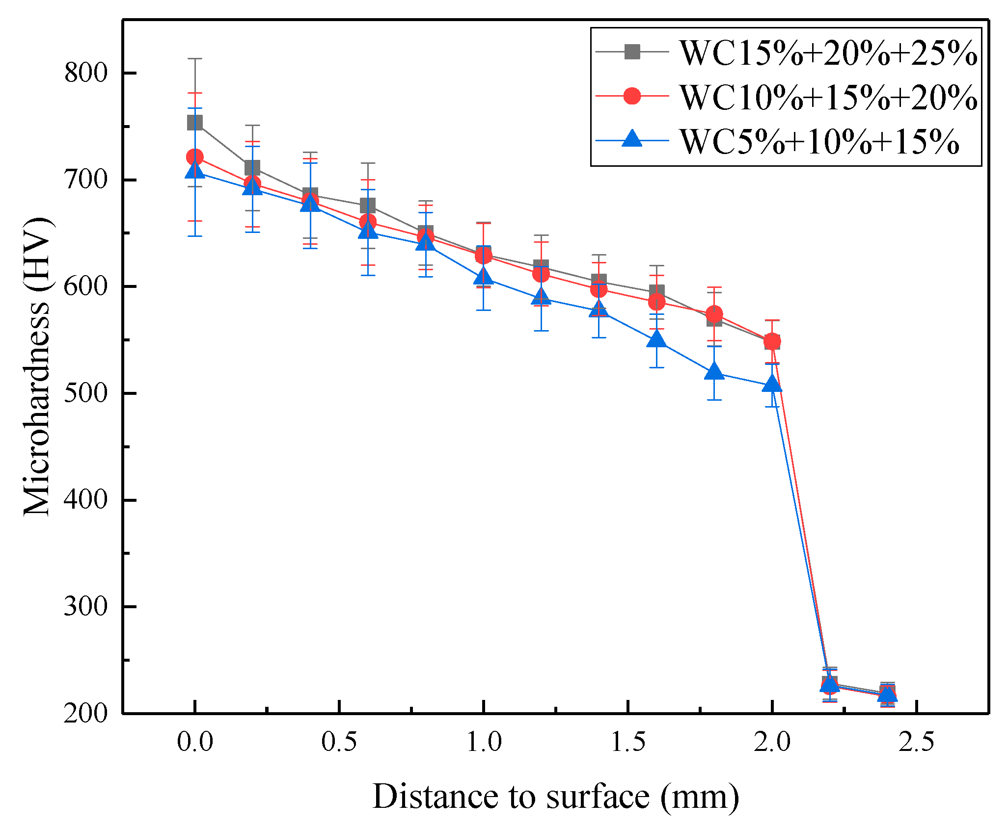
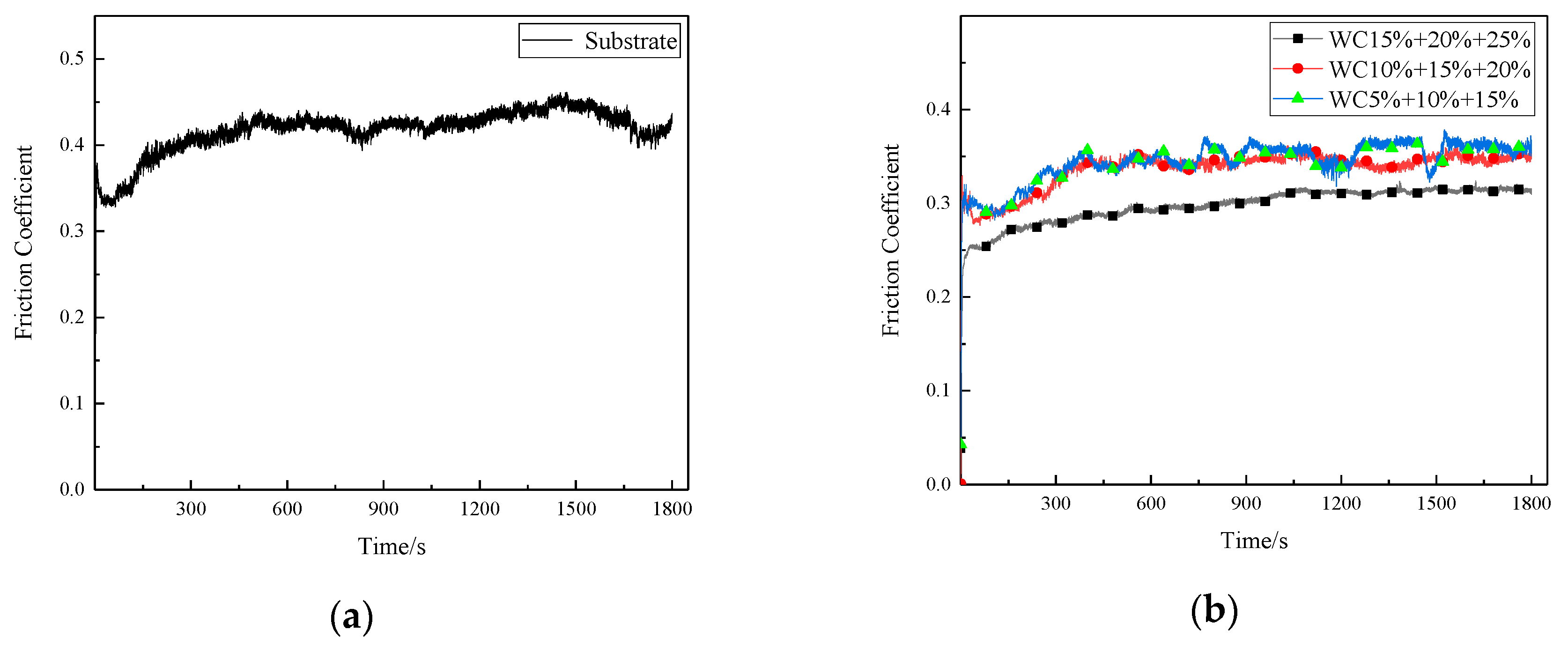
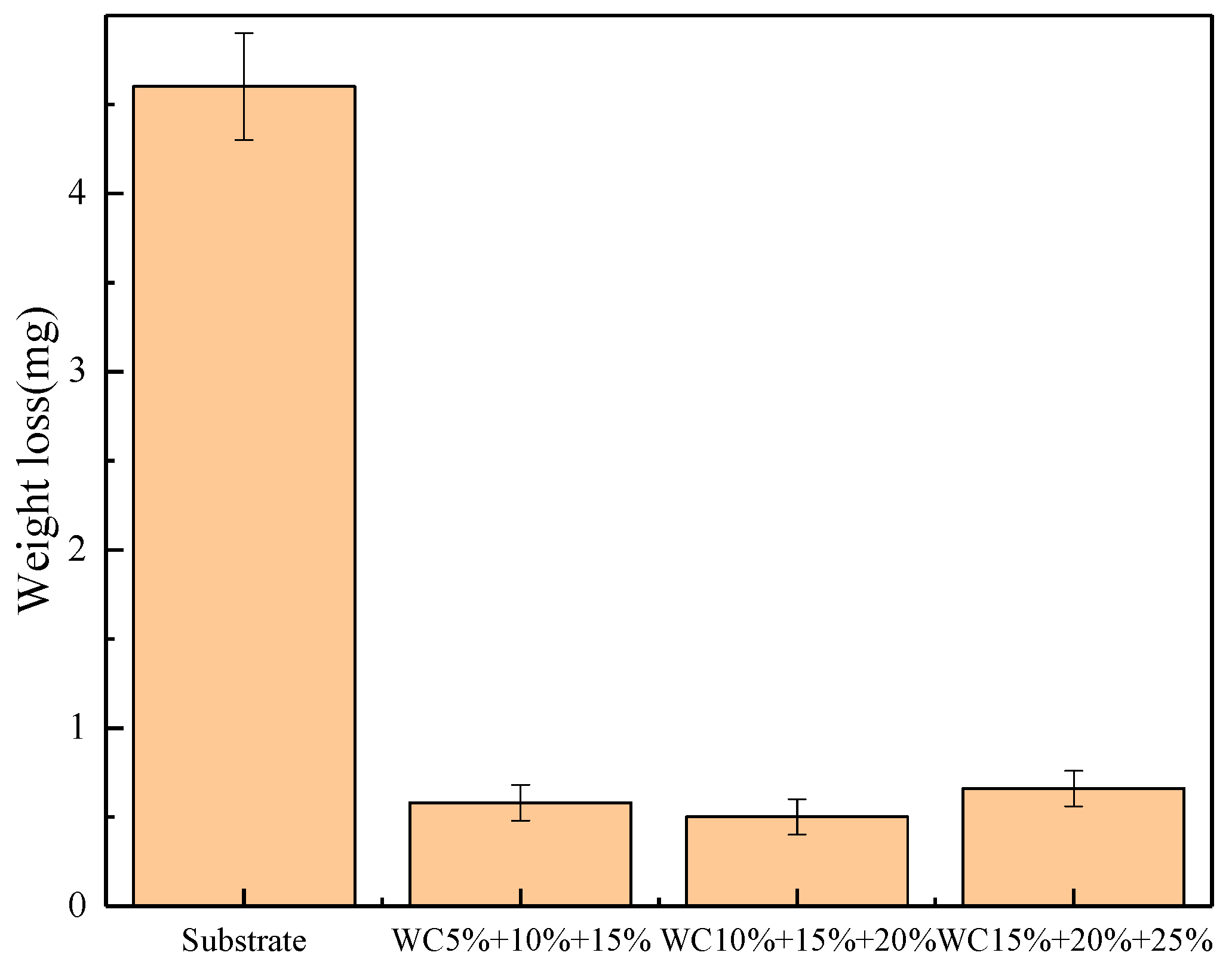
3.2. Hardness and Tribological Measurements

As can be seen from Figure 5, the microhardness values of Co-based gradient coatings are much larger than the substrate, and the average microhardness of the H13 steel substrate is 223 HV. With the increase of WC content, the average hardness of the gradient coatings gradually increases. When the WC content in the coating reaches 25%, the surface hardness of the coating is the largest, which is 681 HV. This is mainly because in the process of cladding, when the content of WC in the composite powder increases, the amount of WC dissolved also increases, which strengthens the effect of solution strengthening. The undissolved WC particles provide the basis for heterogeneous nucleation, and a large number of nucleation blocks the growth of dendrites, making the grains smaller, and achieves the effect of fine grain strengthening. In addition, the amount of undissolved WC and precipitated WC is also increasing, which enhances the dispersion strengthening effect. Therefore, with the increase of WC content, the hardness of the gradient coating is also increasing.
From the surface of the gradient coating to the substrate, the hardness shows a slow gradient decline without obvious sharp steps. This is because the remelting effect of layer-by-layer laser cladding can cause the alloy elements to diffuse again within the previous gradient layer so that the distribution of the number of strengthening phases inside the gradient coating tends to be continuous, and a continuous distribution of hardness appears. Through the design of the gradient coating with gradual composition, the hardness is significantly improved, while the gradient distribution of the hardness can be improved, so that the gradient coating has more excellent mechanical properties.
The curves of the friction coefficients of H13 steel substrate and Co-based gradient coating with time are shown in Figure 6. The friction coefficient of the H13 steel substrate is about 0.45, and the friction coefficients of the Co-based gradient coating are lower than that of the substrate. As the WC content increases, the friction coefficient gradually decreases, mainly because the higher the WC content, the smaller the grain size, the more obvious the effect of fine grain strengthening, and the smaller the surface microstructure. The size difference and distribution of the hard particles on the coating surface cause the friction coefficient of the Co-based gradient coating to fluctuate slightly. As the WC content increases, the surface microstructure is refined, and the fluctuation of the friction coefficient is relatively reduced. When the content of WC is 25%, the friction coefficient is the smallest and most stable.
Figure 7 and Figure 8 show the surface wear morphology of H13 steel substrate and Co-based gradient coating after the wear test. It can be seen that there are some wide furrows parallel to the sliding direction on the wear surface of H13 steel, while the gradient coating surface has almost no cutting and ploughing marks, mainly spalling pits left by brittle spalling, with increasing WC content, spalling marks become more and more obvious, and there are obvious brittle cracks in the unpeeled area. The results show that the main wear mechanism of H13 steel is ploughing and cutting, and after the laser cladding of the gradient coating, the wear mechanism changes to brittle flaking. The hardness of the gradient coating is significantly higher than that of the substrate, and the dispersed WC particles and other hard phases in the coating can effectively prevent the plowing and improve the wear resistance. However, the hard phase is very brittle, and it is easy to cause stress concentration and crack initiation under repeated shear stress. The expansion and intersection of cracks can cause surface spalling in the area where the cracks gather; when the WC content is 25%, the brittle peeling phenomenon on the surface of the coating is the most serious, so the amount of wear increases instead, as shown in Figure 9.

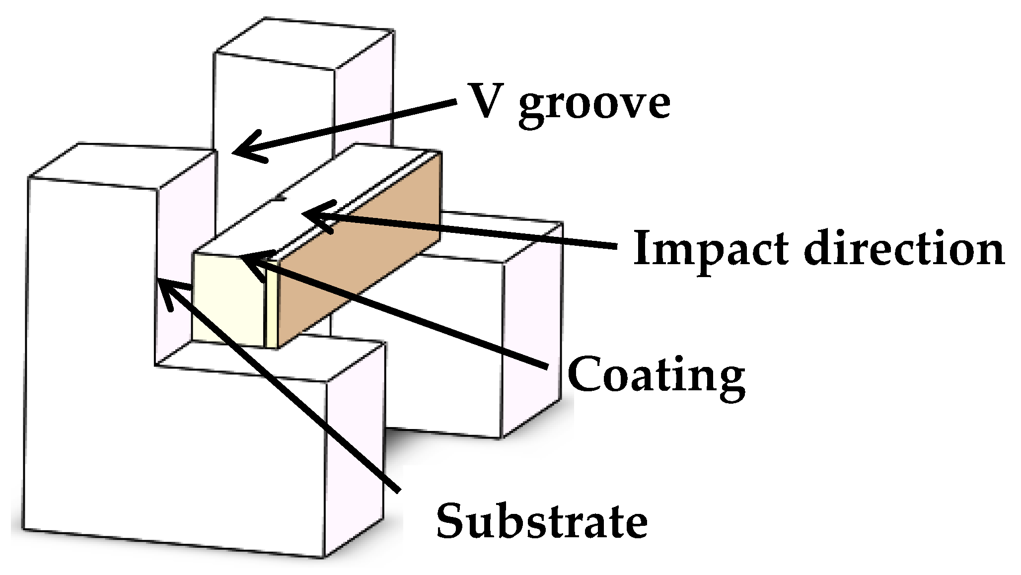
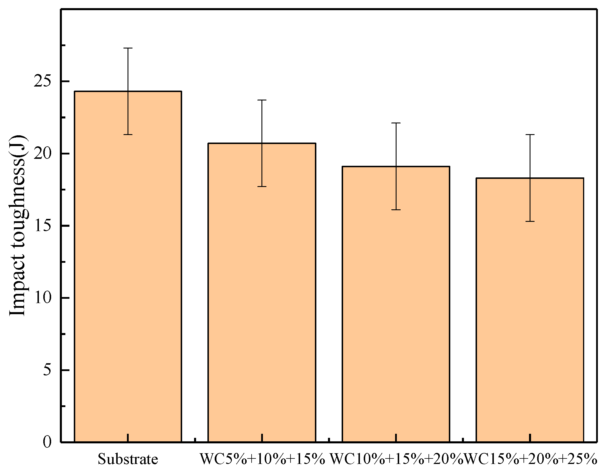
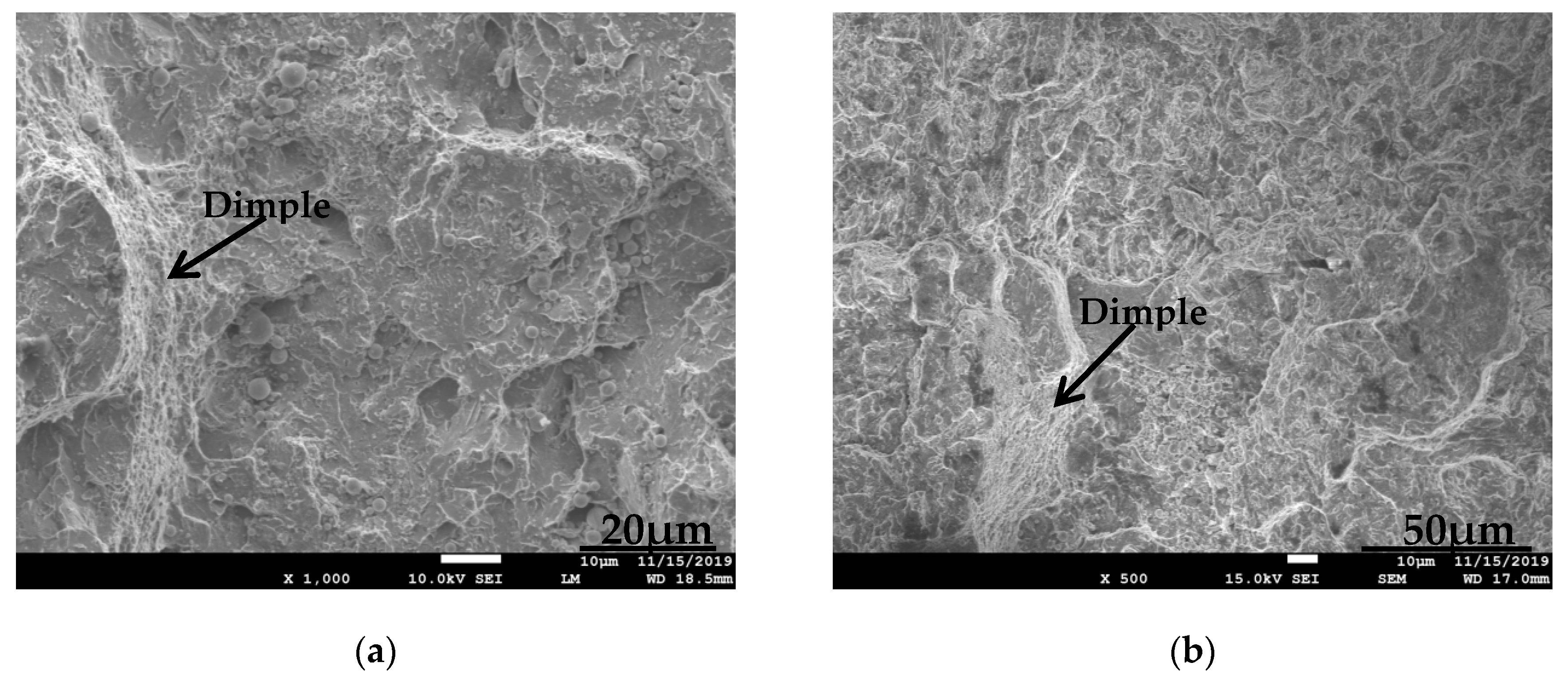
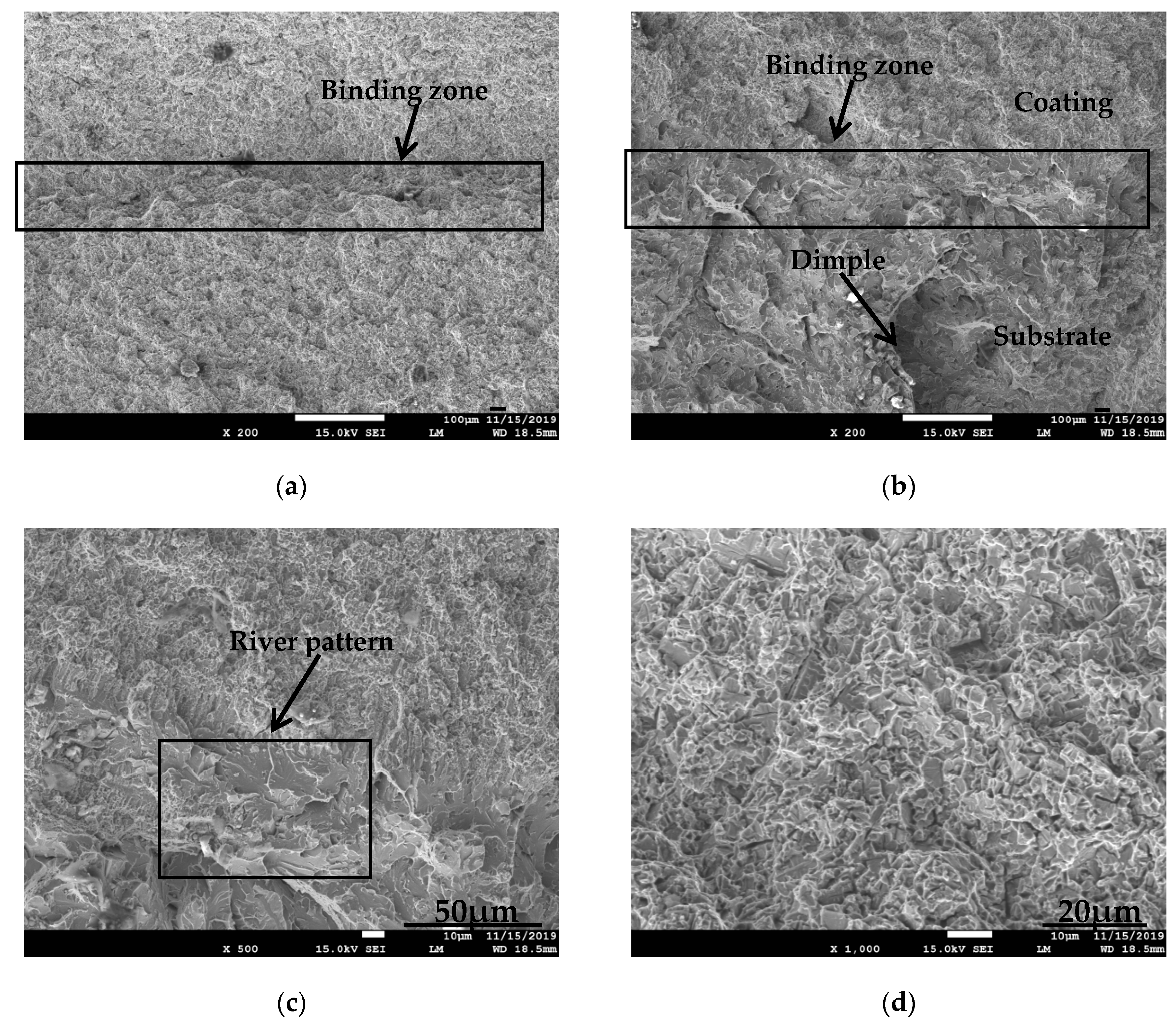
3.3. Impact Toughness Measurements

Impact toughness is the ability of a material to resist deformation and fracture, that is, the ability to absorb energy during plastic deformation and fracture. Figure 10 is the comparison of the impact resistance of the substrate and the gradient coating.
By comparing the impact toughness of the substrate and the Co-based gradient coating, it is known that after the Co-based gradient coating is cladding on the surface of the H13 steel substrate, the impact resistance of the samples is significantly reduced, and the higher the WC content, the worse the impact resistance. The gradient coating not only increases the surface hardness but also increases the brittleness of the material, which makes the impact resistance of the gradient coating lower than that of the base material.
As shown in Figure 11, the fracture surface of the substrate has large undulations, obvious plastic deformation and obvious dimples, which are typical ductile fractures.
It can be seen from Figure 12a that there is an obvious bonding band between the coating and the substrate. In Figure 12b, the fracture morphology of the two sides of the binding band is obviously different. The underside of the binding band is the fracture morphology of the substrate, with obvious dimples, which is characteristic of a ductile fracture. In Figure 12c, the upper side of the bonding band is the fracture morphology of the gradient coating, with obvious river patterns morphology and no dimples, which is characteristic of a brittle fracture.

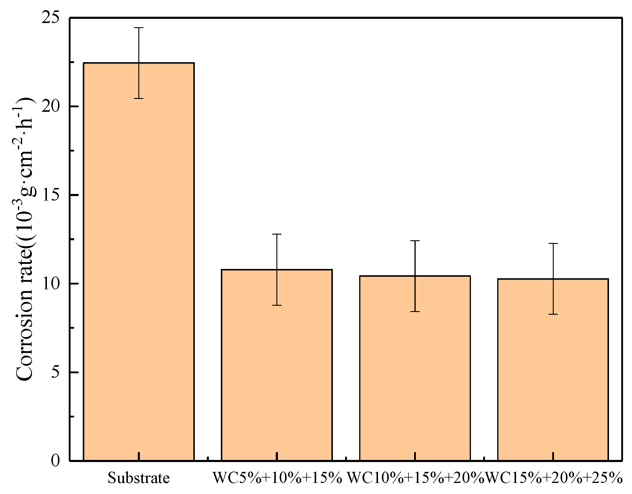
3.4. Corrosion Resistance Measurements

It can be seen from Figure 13 that the corrosion rate of the substrate is the highest, and the corrosion rates of the gradient coating are far less than that of the substrate, which indicates that the gradient coating can effectively improve the corrosion resistance of the material surface, and the higher the content of the reinforcing phase, the better the corrosion resistance of the gradient coating.
Figure 14 shows the surface corrosion morphology of the substrate and the gradient coating. The surface microstructure of the substrate is loose and there are a lot of holes. With the increase of WC content, the corrosion resistance of the coating is gradually enhanced. When the WC content reaches 25%, the microstructure is dense and there are only slight signs of corrosion. During the cladding, strong convection occurs in the high temperature molten pool, so that the WC reinforcing phase is uniformly distributed in the Co-based coating, which has a significant effect on improving the corrosion resistance of the coating.

4. Conclusions

In this study, the Co-based gradient coatings were prepared on the surface of H13 die steel, and the performance differences between the base material and gradient coatings were analyzed by means of microstructure observation, hardness measurement, friction and wear test, impact fracture test, corrosion test, surface and section morphology observation.
The gradient coating forms a good metallurgical bond with the substrate. From the substrate to the coating surface, the hard phase content gradually increases and the microstructure gradually refines. The hardness and wear resistance of the coatings increase with the increase of the hard phase content, the strengthening mechanism is fine grain strengthening, solid solution strengthening and dispersion strengthening.
The main wear mechanism of the substrate surface is ploughing, and the main wear mechanism of the gradient coating surface is brittle peeling. The higher the content of the hard phase, the more obvious the brittle peeling phenomenon.
The impact resistance of the gradient coating is lower than that of the substrate, and the brittleness of the coating increases with the increase of hardness. The fracture mode of the substrate is a ductile fracture, and the fracture mode of the coating is a brittle fracture.
The gradient coatings effectively improve the corrosion resistance of the base material, and the higher the hard phase content, the better the coating’s corrosion resistance.

Author Contributions

Conceptualization, X.Y.; methodology, C.L. and X.Y.; validation, C.L. and X.Y.; data curation, C.L.; writing—original draft preparation, C.L.; writing—review and editing, X.Y.; supervision, S.W., Y.W. and J.C.; project administration, X.Y. All authors have read and agreed to the published version of the manuscript.

Funding

This research was funded by the National Natural Science Foundation of China (grant No. 51575234, 51872122); the Postdoctoral Science Foundation of China (grant No. 2017M620286); the Key Research and Development Program of Shandong Province, China (grant No. 2018CXGC0809); the Agricultural Machinery Equipment Research and Development Innovation Plan of Shandong Province (grant No. 2018YF012); Experts from Taishan Scholars and Youth Innovation in Science & Technology Support Plan of Shandong Province University.

Acknowledgments

Thank you for the experimental equipments provided by the Research Institute of Tribology, University of Jinan, and the teachers for their guidance.

Conflicts of Interest

The authors declare no conflict of interest.

References

  1. Wang, X.Y.; Wang, J.H.; Gao, Z.M.; Xia, D.H.; Hu, W.B. Tempering effects on the microstructure and properties of submerged arc surfacing layers of H13 steel. J. Mater. Process. Technol. 2019, 269, 26–34. [Google Scholar] [CrossRef]
  2. Li, X.; Yan, X.; Zhang, Z. Springback Prediction of a Hot Stamping Component Based on the Area Fractions of Phases. Metals 2019, 9, 694. [Google Scholar] [CrossRef] [Green Version]
  3. Praveen, A.S.; Arjunan, A. Effect of nano-Al2O3 addition on the microstructure and erosion wear of HVOF sprayed NiCrSiB coatings. Mater. Res. Express 2019, 7, 015006. [Google Scholar] [CrossRef] [Green Version]
  4. Praveen, A.S.; Arjunan, A. Parametric optimisation of high-velocity oxy-fuel nickel-chromium-silicon-boron and aluminium-oxide coating to improve erosion wear resistance. Mater. Res. Express 2019, 6, 096560. [Google Scholar] [CrossRef]
  5. Zhu, J.; Zhang, Z.H.; Xie, J.X. Improving strength and ductility of H13 die steel by pre-tempering treatment and its mechanism. Mater. Sci. Eng. A 2019, 752, 101–114. [Google Scholar] [CrossRef]
  6. Zang, C.L.; Zhou, T.; Zhou, H.; Yuan, Y.H.; Zhang, P.; Meng, C.; Zhang, Z.H. Effects of substrate microstructure on biomimetic unit properties and wear resistance of H13 steel processed by laser remelting. Opt. Laser Technol. 2018, 106, 299–310. [Google Scholar] [CrossRef]
  7. Nusrat, T.; Roger, C.; Sumsun, N. Progress in numerical simulation of the laser cladding process. Opt. Lasers Eng. 2019, 122, 151–163. [Google Scholar] [CrossRef]
  8. Rodríguez-Barrero, S.; Fernández-Larrinoa, J.; Azkona, I.; López de Lacalle, L.N.; Polvorosa, R. Enhanced Performance of Nanostructured Coatings for Drilling by Droplet Elimination. Mater. Manuf. Process. 2014, 31, 593–602. [Google Scholar] [CrossRef]
  9. Mohammad, E.; Reza, S.R.; Hassan, A.P.; Hamidreza, M.S. Influence of using electroless Ni-P coated WC-Co powder on laser cladding of stainless steel. Surf. Coat. Technol. 2018, 348, 41–54. [Google Scholar] [CrossRef]
  10. Gao, W.Y.; Chang, C.; Li, G.; Xue, Y.F.; Wang, J.L.; Zhang, Z.Y.; Lin, X.C. Study on the laser cladding of FeCrNi coating. Optik 2019, 178, 950–957. [Google Scholar] [CrossRef]
  11. Alexandru, P.; Julia, M.R.; Elena, M.S. Laser cladding: From experimental research to industrial applications. Mater. Today Proc. 2019, 19, 1059–1065. [Google Scholar] [CrossRef]
  12. Muro, M.; Artola, G.; Leunda, J.; Soriano, C.; Angulo, C. Compositional Modification of Tool Steel to Improve Its Wear Resistance. Metall. Mater. Trans. A 2019, 50, 3912–3921. [Google Scholar] [CrossRef]
  13. Muro, M.; Leunda, J.; Artola, G.; Soriano, C. Microstructural Tuning of a Laser-Cladding Layer by Means of a Mix of Commercial Inconel 625 and AISI H13 Powders. Materials 2019, 12, 544. [Google Scholar] [CrossRef] [PubMed] [Green Version]
  14. Balokhonov, R.R.; Romanova, V.A.; Schmauder, S.; Emelianova, E.S. A numerical study of plastic strain localization and fracture across multiple spatial scales in materials with metal-matrix composite coatings. Theor. Appl. Fract. Mech. 2019, 101, 342–355. [Google Scholar] [CrossRef]
  15. He, X.; Yuan, X.H.; Xu, H.; Song, P.; Yu, X.; Li, C.; Huang, T.H.; Li, Q.L.; Lü, K.Y.; Feng, J.; et al. Analysis of structure and microhardness of Al2O3-40 wt.% TiO2/NiCoCrAl gradient coating with in-situ needle-like phase reinforcement after high-temperature treatment. Ceram. Int. 2019, 45, 14546–14554. [Google Scholar] [CrossRef]
  16. Bai, H.Q.; Zhong, L.S.; Shang, Z.; Xu, Y.H.; Wu, H.; Bai, J.M.; Ding, Y.C. Microstructure and mechanical properties of TiC-Fe surface gradient coating on a pure titanium substrate prepared in situ. J. Alloys Compd. 2019, 771, 406–417. [Google Scholar] [CrossRef]
  17. Zhang, M.Y.; Li, M.; Chi, J.; Wang, S.F.; Yang, S.; Yang, J.; Wei, Y.J. Effect of Ti on microstructure characteristics, carbide precipitation mechanism and tribological behavior of different WC types reinforced Ni-based gradient coating. Surf. Coat. Technol. 2019, 374, 645–655. [Google Scholar] [CrossRef]
  18. Elmkhah, H.; Mahboubi, F.; Abdollah-zadeh, A.; Sabour Rouhaghdam, A.R. A new approach to improve the surface properties of H13 steel for metal forming applications by applying the TiAlN multi-layer coating. J. Manuf. Process. 2018, 32, 873–877. [Google Scholar] [CrossRef]
Figure 1. Schematic diagram of the impact test.
Coatings 10 00176 g001
Figure 2. SEM morphology of cross section of Co-based gradient coating: (a) morphology of the bonding area magnified 400 times; (b) morphology of the bonding area magnified 1000 times.
Coatings 10 00176 g002
Figure 3. Metallographic microstructure of the Co-based gradient coating cross section: (a) crystal microstructure of binding zone with magnification of 1000 times; (b) crystal microstructure of coating with magnification of 500 times; (c) crystal microstructure of coating with magnification of 1000 times.
Coatings 10 00176 g003
Figure 4. X-ray diffraction pattern of Co-based gradient coating surface.
Coatings 10 00176 g004
Figure 5. Microhardness distribution of the cross section of Co-based gradient coating.
Coatings 10 00176 g005
Figure 6. Friction coefficients of H13 steel substrate and Co-based gradient coating: (a) friction coefficient curve of H13 steel substrate; (b) friction coefficient curves of gradient coatings.
Coatings 10 00176 g006
Figure 7. Wear morphology of H13 steel substrate surface: (a) Surface wear morphology of the substrate at a magnification of 200 times; (b) Surface wear morphology of the substrate at a magnification of 200 times.
Coatings 10 00176 g007
Figure 8. Abrasion morphology of Co-based gradient coating surface: (a) Wear morphology of the gradient coating with WC content of 5% + 10% + 15%; (b) wear morphology of the gradient coatings with WC content of 10% + 15% + 20%; (c) wear morphology of the gradient coatings with WC content of 15% + 20% + 25%.
Coatings 10 00176 g008
Figure 9. Comparison of wear loss between substrate and Co-based gradient coating.
Coatings 10 00176 g009
Figure 10. Comparison of impact resistance of substrate and Co-based gradient coatings.
Coatings 10 00176 g010
Figure 11. SEM morphology of impact fracture of H13 steel substrate: (a) Fracture morphology of the substrate at a magnification of 1000 times; (b) Fracture morphology of the substrate at a magnification of 500 times.
Coatings 10 00176 g011
Figure 12. SEM morphology of impact fracture of Co-based gradient coating: (a,b) fracture morphology of binding zone; (c,d) fracture morphology of gradient coating.
Coatings 10 00176 g012
Figure 13. Corrosion rate comparison of substrate and Co-based gradient coatings.
Coatings 10 00176 g013
Figure 14. Corrosion morphology of substrate and Co-based gradient coating: (a) corrosion morphology of the substrate; (b) corrosion morphology of the gradient coating with WC content of 5% + 10% + 15%; (c) corrosion morphology of the gradient coating with WC content of 10% + 15% + 20%; (d) corrosion morphology of the gradient coating with WC content of 15% + 20% + 25%.
Coatings 10 00176 g014aCoatings 10 00176 g014b
Table 1. Chemical composition of H13 steel.
ElementCSiMnCrMoVPSFe
Content (wt.%)0.32~0.450.80~1.200.20~0.504.75~5.501.10~1.750.80~1.20≤0.03≤0.03Bal.
Table 2. Chemical composition of Co-based self-fluxing alloy powder.
ElementCSiMnCrMoFeNiWCo
Content (wt.%)1.151.100.5029.001.003.003.004.00Bal.
Table 3. Proportion of Co-based gradient coating composite powder.
First LayerSecond LayerThird Layer
First sample95% Co + 5% WC 90% Co + 10% WC85% Co + 15% WC
Second sample90% Co + 10% WC 85% Co + 15% WC 80% Co + 20% WC
Third sample85% Co + 15% WC 80% Co + 20% WC 75% Co + 25% WC
Table 4. Optimal parameters combination for laser cladding test.
ParameterDefocusing Amount (mm)Frequency (Hz)Scanning Speed (mm/min) Pulse Width (ms)Single Pulse Energy (J)
Value2030100 2.0 6.5

