Article

Property of TiO2-15MgAl2O4 Electrical-Heating Coating Prepared by Atmospheric Plasma Spraying and Hydrogen Heat Treatment

1
School of Materials Science and Engineering, Central South University, Changsha 410083, China
2
Guangdong Institute of New Materials, National Engineering Laboratory for Modern Materials Surface Engineering Technology, Key Lab of Guangdong for Modern Surface Engineering Technology, Guangzhou 510650, China
*
Author to whom correspondence should be addressed.
Coatings 2020, 10(2), 177; https://doi.org/10.3390/coatings10020177
Submission received: 18 December 2019 / Revised: 23 January 2020 / Accepted: 5 February 2020 / Published: 14 February 2020
(This article belongs to the Section Plasma Coatings, Surfaces & Interfaces)

Abstract

:
Using TiO2-15MgAl2O4 mixed powder as spray-feed, an electrical-heating coating was successfully fabricated by atmospheric plasma spraying technology. The phase composition, microstructure, and electrical-heating performance of the coating were characterized by XRD, SEM, and cyclic electrification tests, respectively. The coating samples were heat-treated at 350 °C in a hydrogen atmosphere. The results show that TiO2-15MgAl2O4 coating can be heated over 300 °C within 30 m at 55.1 V which preserves heat for a long time. Before heat treatment, the available heating temperature of the coating decreases significantly with electrification cycles. The resistivity of coating rises rapidly during the cyclic electricity test. After hydrogen heat treatment, the electrical-heating property of coatings is significantly enhanced.

1. Introduction

Heating rollers are widely used in plastic calendar, film lamination, paper drying, deep processing of non-woven materials and laser anti-counterfeiting printing. The traditional heating roller is mainly a fluid heating system. Oil and steam are used as the medium to heat the roller. Problems such as high maintenance cost, poor temperature uniformity, large energy loss, and potential safety problems lead to its elimination. The electromagnetic heating roller based on magnetic induction heating has the advantages of good temperature distribution and no pollution. However, it needs to heat within a cavity, and the heat is transmitted to products through the wall metal. This results in low thermal conversion efficiency and high energy consumption. In addition, its complex structure design increases costs.
The electrical-heating coating roller is a new type of heating roller which uses a thermal spraying method to spray electrothermal materials on the surface of the roller. It can be heated on the surface of the roller and directly conduct heat to products. It greatly enhances the heating efficiency of the heating roller. Recently, researchers used carbonaceous materials as heating elements to fabricate heaters, including carbon nanotubes (CNTS), graphene, and carbon fiber [1,2,3]. The carbonaceous composite material electrical heaters are mainly applied in flexible conductors and low-power applications, including wearable heating equipment, defogger devices, and indoor climate control heater [4,5,6]. The common metal electrical-heating materials include nickel-chromium alloy, iron-aluminum alloy, copper-based alloy, etc. [7]. Due to the low resistivity of metal electrical-heating materials, the metal layer is usually thin and complex in structure (spiral or coil) in order to achieve the resistance required for a certain level of heat energy [8]. This will lead to a serious inductive effect, resulting in energy loss. On the other hand, metal electrical-heating materials will inevitably be oxidized in the process of electrified heating, which results in increased resistance and locally elevated temperature of metal layer [9]. To overcome the problems above, the ceramic electrical-heating materials have attracted much more attention because of its controllable resistivity, good oxidation resistance, and stable chemical properties [10,11,12,13,14].
Recent photocatalysis research has focused on TiO2 because of its excellent photochemical properties [15,16,17,18]. There has been little reported on using TiO2 as electricity-driven resistive heaters. TiO2 is an excellent thermal spraying material with good thermal stability, high spraying deposition efficiency, tight coating-bonding, and low cost [19]. Stoichiometric TiO2 is not conductive. Rutile TiO2 is an insulator at room temperature, but non-stoichiometric TiO2–x is a p-type semiconductor material [20,21] whose conductivity is attributed to oxygen vacancies. Toma et al. fabricated TiO2-Cr2O3 coating by an atmospheric plasma spraying method. The coatings are prone to re-oxidization when the temperature exceeds 300 °C [22]. Recent studies by Bobzin have shown that anisotropic cracks in TiO2-Cr2O3 coating lead to inhomogeneous temperature distributions on the surface of the coating [23].
In this paper, the composite powder of TiO2 and MgAl2O4 is used as electrical-heating material to prepare coating by atmospheric plasma spraying. MgAl2O4 is included in the design as the insulating layer. On the one hand, the gradient change of composition between the heating layer and the insulating layer can reduce the thermal stress caused due to different thermal expansion coefficients, enhancing the bonding strength of different layers. On the other hand, non-conductive MgAl2O4 can regulate the resistivity of TiO2 coatings in order to meet the requirements of high voltage and low current in industrial applications. The hydrogen heat treatment was used to improve the electrical-heating property of the coating.

2. Experimental Procedure

2.1. Experimental Materials

In this experiment, the composite coating system was sprayed on 310S stainless steel pipes (φ23 mm × 294 mm) and 310S stainless steel disc substrates (φ25.4 mm × 6 mm), respectively. As shown in Figure 1, the coating system consists of three layers. The bottom layer is a bonding coating, which decreases the thermal stress caused by different thermal expansion coefficient and improves the bonding strength between the coating system and the substrate. The top layer is the electrical-heating coating, which is used as a heat source after it is electrified. The middle layer is an insulating coating, which is used to insulate the heating layer and the substrate. There is a pair of copper hoops at two edges of the pipe which is used to load voltage and operates as an electrode.
The feedstock of the bonding coating is Ni-Al alloy powder (particle size 45–95 μm, purity > 99%). Ni-Al coating matches well with the steel matrix in thermal and physical properties, which is beneficial for enhancing the bonding strength between the coating system and matrix [24]. The feedstock of the insulating coating is comprised of MgAl2O4 powder (particle size 10–45 μm, purity > 99%). Compared with Al2O3, MgAl2O4 has no phase transition during the spraying process and has better performance for temperature and humidity [25]. A mixture of commercial black TiO2 powder (particle size 15–45 μm, purity > 99%) and MgAl2O4 powder (particle size 10–45 μm, purity > 99%) were used as spray-feed to produce the heating coatings. Previous exploratory experiments showed that when the addition of MgAl2O4 was 30%, the resistance of the coating increased, resulting in lower working current and joule heat. In this study, TiO2-15MgAl2O4 (TM15) powder was mixed at a mass fraction ratio of 85:15 to fabricate electrical-heating coating.

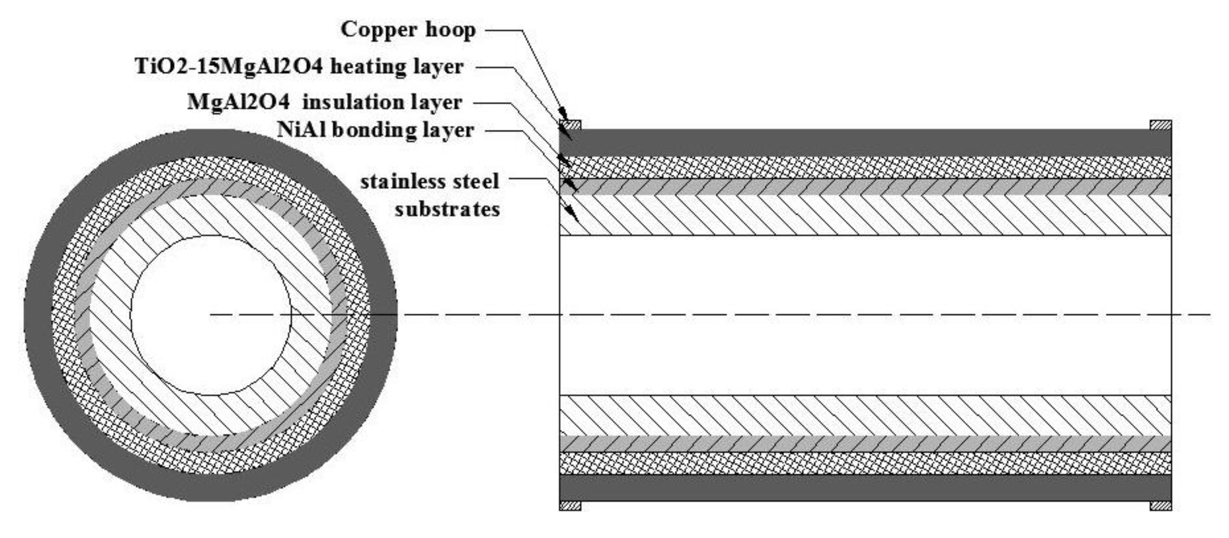
2.2. Preparation of Coating and Hydrogen Heat Treatment

Before spraying, the substrate was degreased by gasoline ultrasonic and then cleaned by alcohol. The substrate was sandblasted by #46brown corundum under pressure of 0.4 MPa. The oil and oxide on the surface of the substrate were removed. The roughness was increased to enhance the bonding strength between the coating and the substrate. The bonding layer, insulating layer, and the heating layer were all prepared by atmospheric plasma spraying. The spraying equipment used was the MF-P1000 atmospheric plasma spraying system (GTV) attached with an F6 gun (Oerlikon-Metco). The parameters used for the spraying process are shown in Table 1.
The pipe and disc samples were heat-treated at 350 °C at a heating rate of 7 °C /min and cooled to room temperature in a vacuum furnace. The corresponding holding time was 6 h. The heat treatment was operated under a hydrogen flow rate of 100 mL/min.

2.3. Performance Characterization of Coatings

The phase composition of powders and coatings was examined by X-ray diffraction (XRD, Smartlab 9 kW, RIGAKU) (Tokyo, Japan using Cu Kβ radiation at a scanning rate of 10°/min at Bragger angle (2θ) between 10° and 90°. The microstructure and chemical composition of the coatings were characterized by scanning electron microscopy (SEM, Nova-Nona-430, FEI) equipped with an energy dispersive spectrometer (EDS).
The electrical-heating property of TM15 coating was researched by a cyclic electrification test. DC stabilized voltage power supply (KXN-6020D) (Shenzhen, Guangdong, China was selected for the power equipment. The power supply voltage was kept stable at 55.1 V during the electrification test. A cycle of electrification test comprises of heating the coating from room temperature to maximum temperature and then turning off the power to cool to room temperature after holding for 11 h. The temperature of the heating layer was measured by an infrared thermometer (UNI-T, UT303D) (Shenzhen, Guangdong, China. The temperature distribution of coating was observed through infrared thermal imager (UNI-T, UTi80) (Shenzhen, Guangdong, China. The resistance of the coating (R) was calculated by Equation (1) using the online voltage and current displayed on the power supply,
R = U I
where U denotes the loading voltage and I the working electricity. Furthermore, the resistivity ( ρ ) can be calculated by
ρ = R · S L
where S represents the cross-sectional area of heating coating perpendicular to the electrical current and L the length of the heating coating in the direction of the electrical current.

3. Results and Discussion

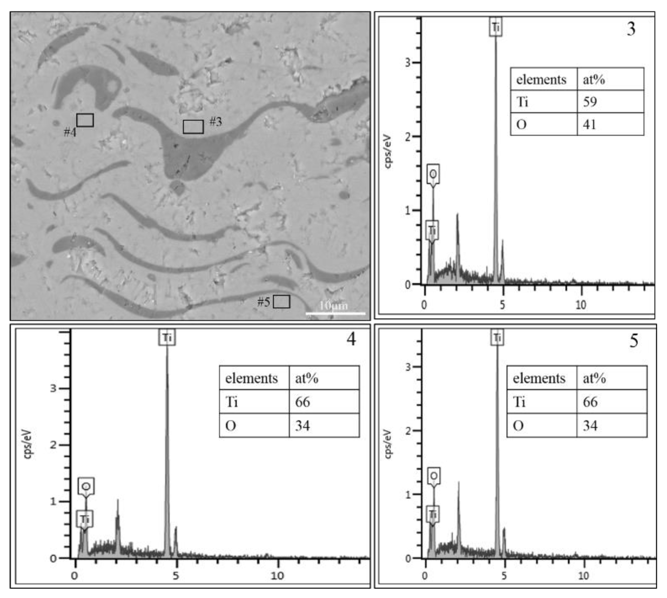
3.1. Phase Composition and Microstructure

Figure 2 shows the XRD pattern of TM15 raw powder and coating. It can be seen from the pattern that the TM15 mixed powders include rutile TiO2, Ti3O5, MgAl2O4, Ti7O13, and a series of other sub-stoichiometric titanium oxides. This is because the employed black TiO2 powders are agglomerated and sintered in a vacuum environment, inducing the complex lattice anoxia of TiO2. The peak intensities of the powder XRD pattern indicate that the rutile TiO2 has the highest content. There are Ti3O5, rutile TiO2, Ti4O7, MgAl2O4, and TiO phases in the TM15 coating. The peak intensity corresponding to the Ti3O5 phase in TM15 coating is the strongest, which indicates that the content of the Ti3O5 phase is the highest in TM15 coating. The sub-stoichiometric phase of powders reduced titanium oxides of more anoxia after spraying, e.g., 2θ = 29° (Ti7O13 to Ti4O7), 36° (Ti5O9 to Ti3O5), 41° (Ti7O13 to Ti3O5), 56° (Ti7O13 to Ti3O5). As for TinO2n–1, the lower the n, the more anoxia is induced in titanium oxides and the greater the conductivity. In the process of thermal spraying, the molten TiO2 particles caused lattice anoxia in the high-temperature flame flow under low oxygen partial pressure [26]. In addition, hydrogen plasma has a strong reduction effect on TiO2, promoting the formation of anoxic phase in the coating during the spraying process [27]. Diffraction peaks of MgAl2O4 could be detected in both coatings and powders, but no peaks of other phases of Mg and Al elements. This indicates that the structure of MgAl2O4 is stable and phase transformation will not occur during spraying.
Figure 3 shows the surface morphology of the TM15 coating. In Figure 3a, under low magnification, the coating surface is rough, which is composed of a melting zone and an incomplete melting zone. The coating is in the shape of high and low peaks. Figure 3b shows, under high magnification, that the splats in the melting region have spread completely and are smooth. Some reticular cracks are observed in the melting region, which is caused by the residual thermal stress released at the interface of molten particles during the cooling process of the coating [28,29].
Figure 4 shows the polished cross-section of the whole electrical-heating coating system. It can be seen from the figure that the electrical-heating coating system has a dense structure, uniform thickness, and close bonds without cracks. The average thickness of the bonding layer, insulation layer, and heating layer is about 65, 260, 320 μm, respectively. The cross-sectional microstructure shows that the coating has a dense stacking structure (Figure 4). The black phase is distributed evenly in a wavy form in the gray phase matrix, with obvious phase interface. In the spraying process, the feedstock is heated by a plasma jet at a temperature of up to 15,000 K and then melted into a droplet or semi-molten particle, which impacts the substrate at a velocity of up to 800 m/s. Molten droplets or semi-molten particles deform and spread on the substrate due to the kinetic energy impact, accumulating on the substrate and solidifying rapidly into a stacking structure [30,31]. From the analysis by EDS, it can be determined that the black phase in SEM imaging is MgAl2O4. It can be evaluated that the gray matrix phase is TiO2–X, containing a large amount of anoxia as determined from BSE imaging and the EDS analysis in Figure 5.

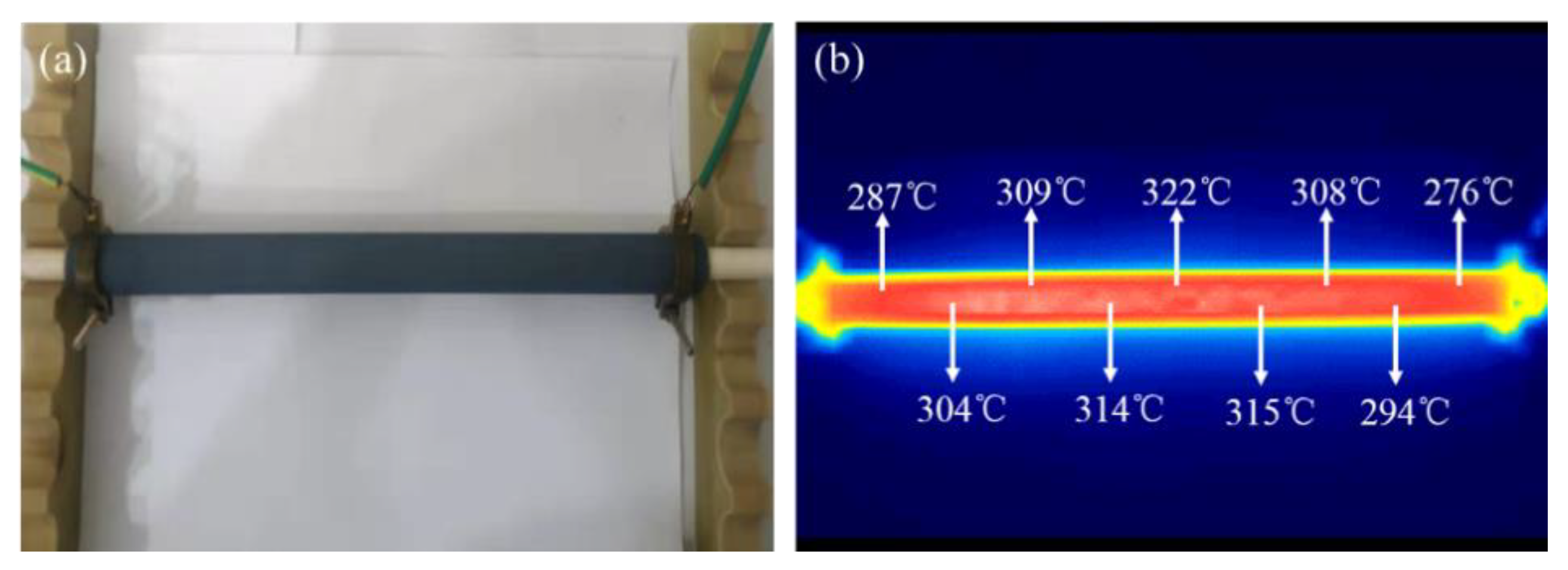
3.2. Electrical-Heating Properties

Figure 6a shows the pipe sample of TM15 electrical-heating coating. The sprayed TM15 coating is shown as a gray-black color. Figure 6b shows the infrared thermal imaging picture of TM15 coating in the holding stage. From the temperatures shown, it can be seen that the surface temperature of the heating pipe is relatively uniform. The temperature difference in the middle of the pipe is no more than 20 °C. The temperature difference between the edges and middle of the pipe is mainly due to the heat loss by thermal radiation and convection [22,32].
Figure 7 shows the temperature–time curve of TM15 coating tested by five cycles of electrification. The indicated temperature is the highest temperature on the coating surface, which is basically in the middle of the pipe. It can be seen from the figure that the temperature of the pipe rises rapidly in the heating stage. It can be heated to the highest temperature within 30 min. The temperature in the holding stage can remain stable for a long time. However, as the cycles of electrification increases, the highest heating temperature gradually decreases and changes greatly. During the first and second electrical-heating tests, the heating pipe can be heated to 321 and 312 °C respectively. However, in the next three electrification cycle tests, the heating pipes can only be heated to 273, 224 and 218 °C, respectively. According to Equation (3), at a constant voltage and increased resistance, decreased power was loaded on the coating. According to Equation (4), for the same electrification times, the temperature of the coating has a positive correlation with the joule heat. The increased resistance results in the decline of thermal effect. For the same heating pipe, the cross-sectional area and length of the heating pipe are identical. According to Equation (5), the resistance of the heating pipe is directly determined by the resistivity of the conductive layer. It seems that the available heating temperature of the coating is linearly related to the resistivity. However, the actual situation does not support this inference. Figure 8 shows the coating resistivity of five cycles in the heat preservation stage. Comparisons show that the resistivity increases with electrification cycles. The resistivity value of the fifth cycle is 5.59 times higher than that of the first cycle while the temperature is 321/218. It must be also considered that the temperature of the coating surface is not uniform as shown in Figure 6. Furthermore, there are some inherent defects in the coating, such as pores and micro-cracks, and changes have occurred in these defect areas during the cyclic electrification tests. This is discussed in detail in Figure 11.
P   =   U   I   =   U 2 R
T∝Q = P t
R   =   ρ L S
Figure 9b shows that the resistivity of TM15 coating decreases rapidly with time in the heating stage of 0–30 min. As electrification time increases, the coating attains more joule heat increasing the temperature. Therefore, electrons of the coatings move more intensively and move out of their original orbit easily. With the help of the heat energy introduced into the coating, more electrons gain energy and transit to higher energy levels, which is called the conduction band. When an electron transits to the conduction band, an electron hole remains behind. The electron from neighboring atoms tends to fill the electron hole. This will lead to the movement of more electron holes. In the case of TiO2, electron holes are attributed to oxygen vacancies. In Figure 4 and Figure 5, the MgAl2O4 is distributed uniformly in TiO2–x as many wavy strips. MgAl2O4 is not conductive. When an oxygen vacancy moves to encounter MgAl2O4, it is impossible to move across through MgAl2O4 directly, but it moves along with the meander interface. This increases the motion path of the electron hole effectively so that the coating has a certain resistance for joule heat. As the temperature increases, oxygen vacancies move faster, sharply decreasing resistivity. After 30 min, the temperature of the coating fails to increase. The concentration and transfer rate of oxygen vacancies reach stability and the resistivity no longer changes.
Figure 10 shows the resistivity–temperature curve at different cyclic electrification tests in the heating stage. From the graph, it can be observed that the resistivity of TM15 coating decreases with the temperature, showing a negative temperature coefficient of resistance (NTC), which is similar to semiconductor materials. The resistivity of TM15 coating decreases slowly with temperature in the first cycle. As the number of cycles increases, resistivity declines faster. The cyclic electrification test is a kind of heat treatment in an atmospheric environment for TM15 coatings. The coatings need to undergo rapid heating, long-term heat preservation, air cooling, and multiple cycles. The anoxic phase is prone to oxidization in this process [33]. In the present study, this statement has been further verified. Figure 11 shows the cross-sectional morphology of electrical-heating coating after a cyclic electrification test. It can be observed that there are more pores and micro-cracks in the cross-section of coating than as-sprayed coatings. The size of pores and cracks are about 0.1–0.5 µm in diameter, 2–5 µm in length, respectively. The pores and cracks distribute mostly in TiO2–X matrix. It is worth noting that the average ratio of oxygen atoms in the TiO2–X matrix has increased by 10%, from 36% in Figure 5 to 46% in Figure 11. Particularly, the ratio of oxygen atoms in the areas near pores and cracks is higher than other smooth sections. This demonstrates that the oxidation of TM15 electrical-heating coating during electrification occurs preferentially in the defects of the coating.

3.3. Effect of Hydrogen Heat Treatment on Coating Electrical-Heating Properties

Some studies [34,35] have shown that a hydrogen atmosphere can promote rutile TiO2 to form non-stoichiometric TiO2 (anoxia phases of titanium dioxide). The contents of non-stoichiometric TiO2 have an important influence on the conductivity of TiO2 coating. The higher the content of non-stoichiometric TiO2, the higher the conductivity of TiO2 coating [36,37]. Figure 12 shows the temperature–time curve of the cyclic electrification test of coatings after 350 °C heat treatment. During 10 cycles of electrification, the coatings can be heated stably to above 300 °C within 30 min and kept for 11 h. Compared to coatings without heat treatment in Figure 7, it can be found that the heat-treated coating can still be heated to 324 °C after 5 cycles of electrification and 310 °C after 10 cycles of electrification, much higher than 218 °C in Figure 7. The heating temperature of heat-treated coatings remains stable from the fifth cycle. It illustrates that the hydrogen heat treatment effectively improves the heating property of TM15 coating.
As is shown in Figure 13, the resistivity of heat-treated TM15 coating decreases rapidly in the heating stage and kept stably in the holding stage, which is consistent with that of TM15 coating without heat treatment. The resistivity of heat-treated TM15 coating after five cycles is lower than that of non-heated ones. It is demonstrated that the conductivity of heat-treated TM15 coating is better than that of non-heat treatment one. After heat treatment, the coating resistivity of the fifth cycle electrification test is only 2.3 times higher than the first cycle and the resistivity of the tenth cycle is only 3.3 times higher than the first cycle. Compared with the TM15 coating before heat treatment, the resistivity stability of heat-treated TM15 coating is greatly improved. After hydrogen heat treatment, the coating resistivity of multiple electrification cycles is lower than that of non-heat-treated coatings, and the variation of resistivity is much smaller. It can be observed that the contents of Ti3O5 increases significantly after hydrogen heat treatment in Figure 14. Ti3O5 is relatively conductive among sub-stoichiometric titanium oxides. This finding is in accordance with the results in [35,36].

4. Conclusions

The TiO2-15MgAl2O4 coating for electric heating was successfully synthesized by an atmospheric plasma spraying method. The phase composition, microstructures, and electrical-heating properties were investigated systematically. Some important conclusions can be drawn as follows:
(1)
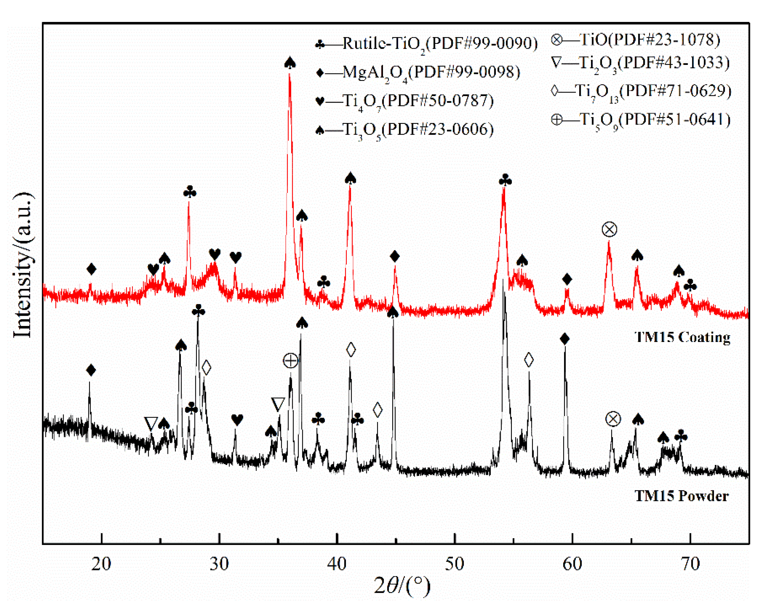
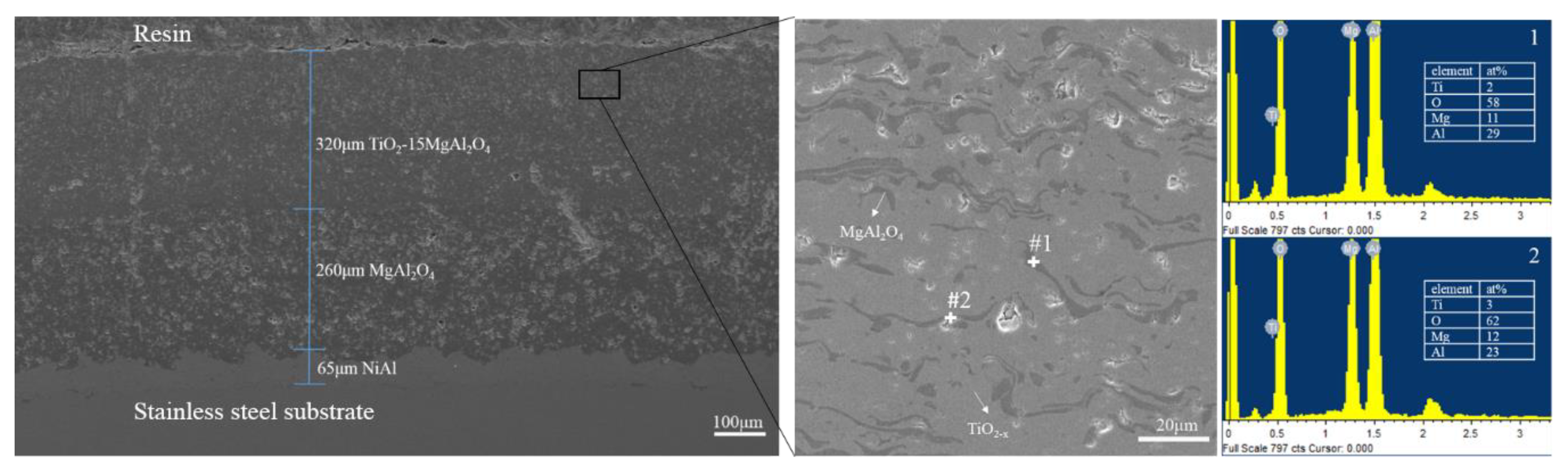
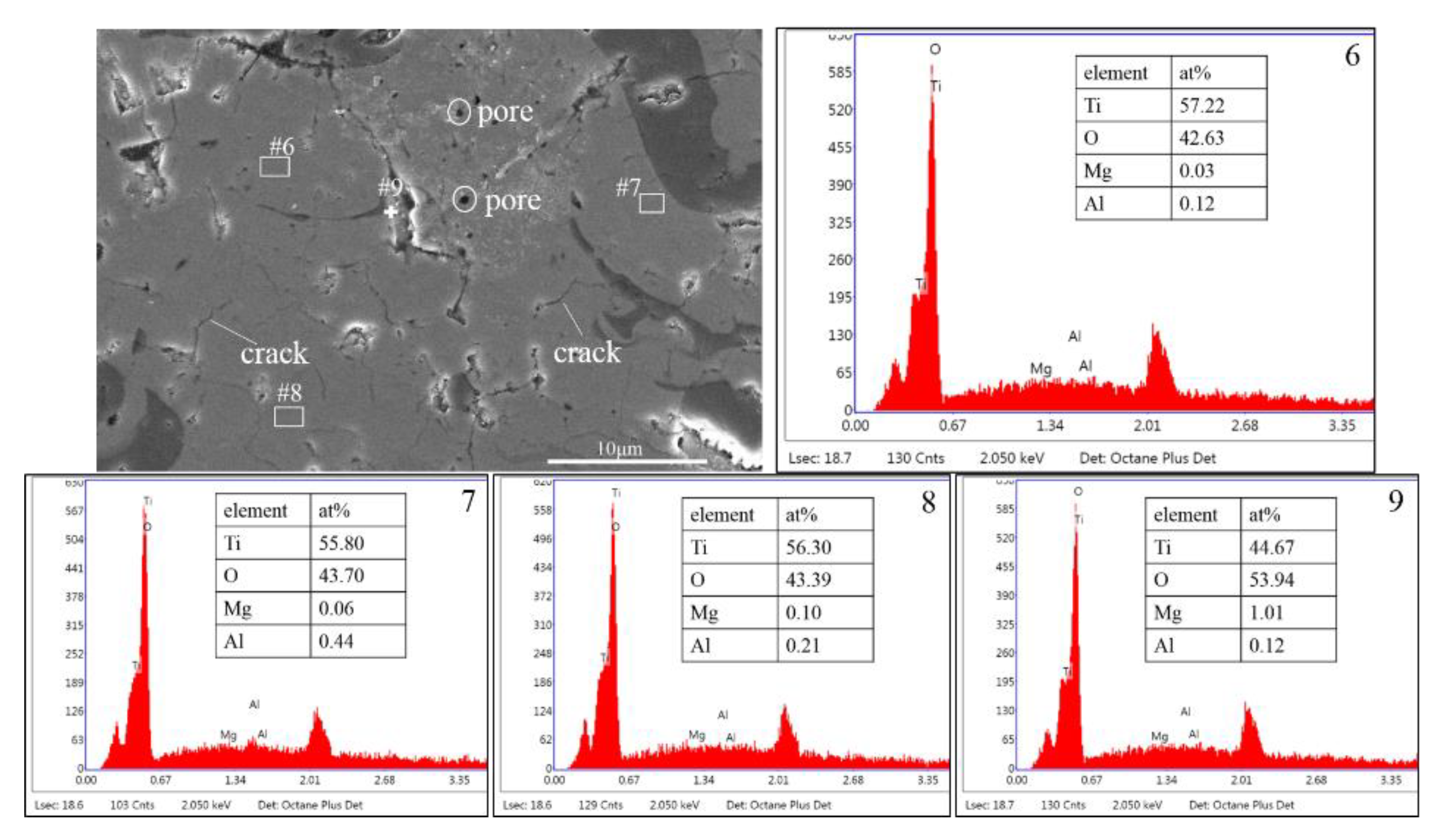
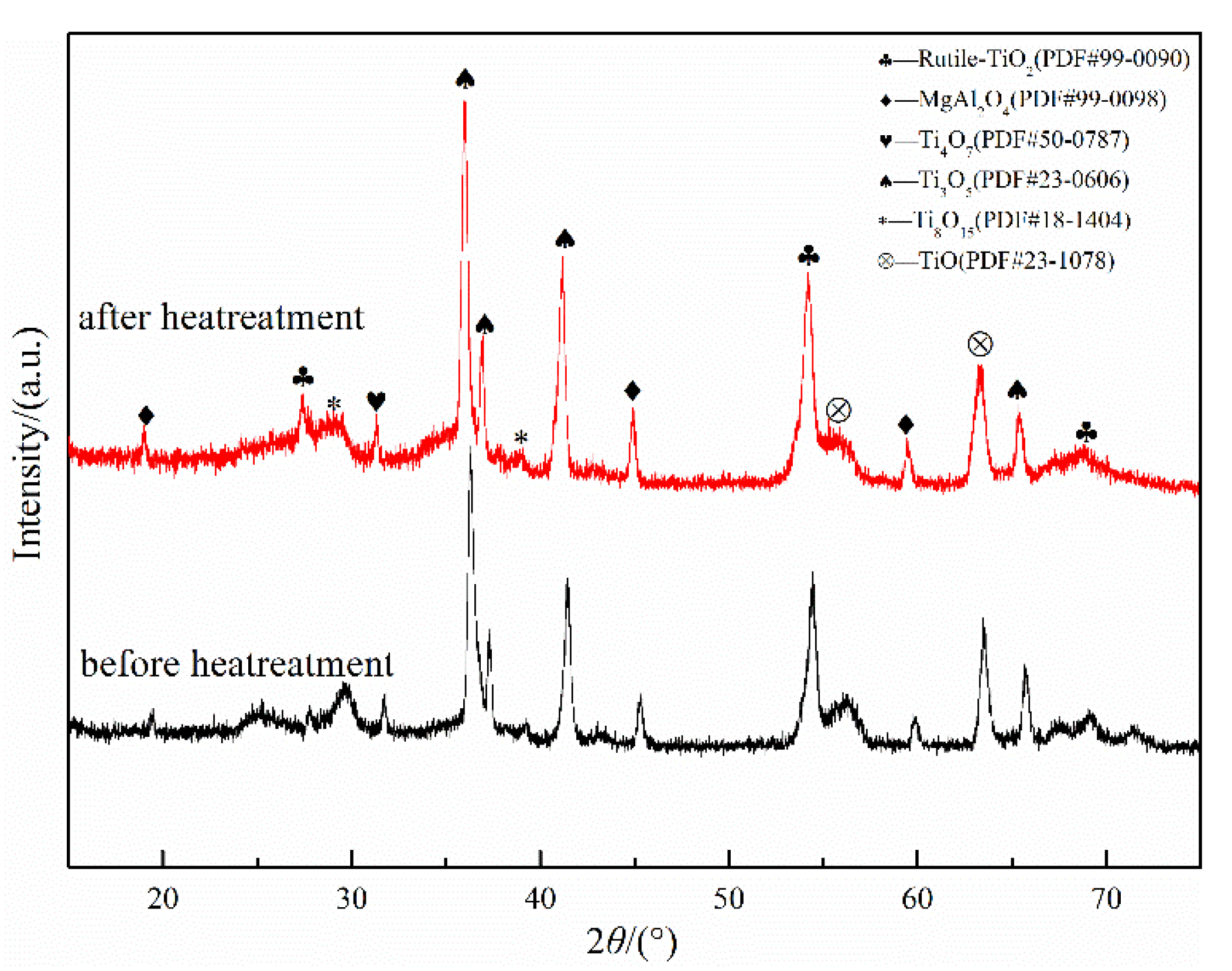
The phases of atmospheric plasma sprayed TiO2-15MgAl2O4 coating include Ti3O5, rutile TiO2, Ti4O7, MgAl2O4, and TiO phase. The MgAl2O4 distributes uniformly in a wavy strip in the TiO2–x matrix.
(2)
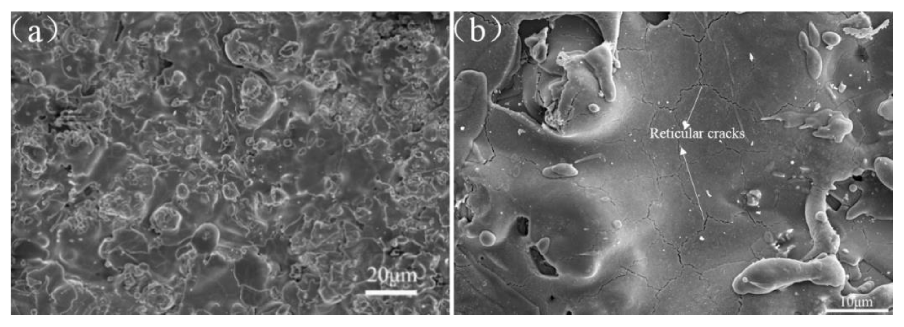
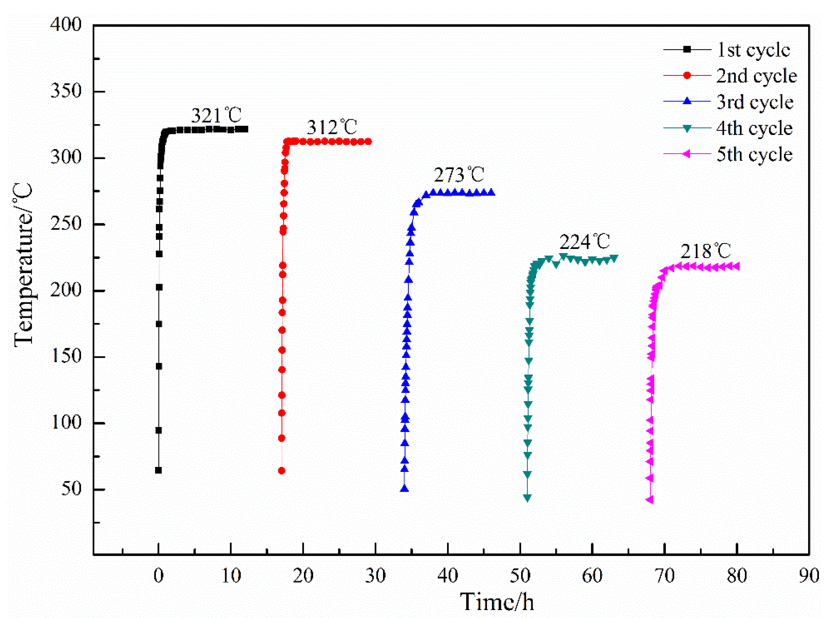
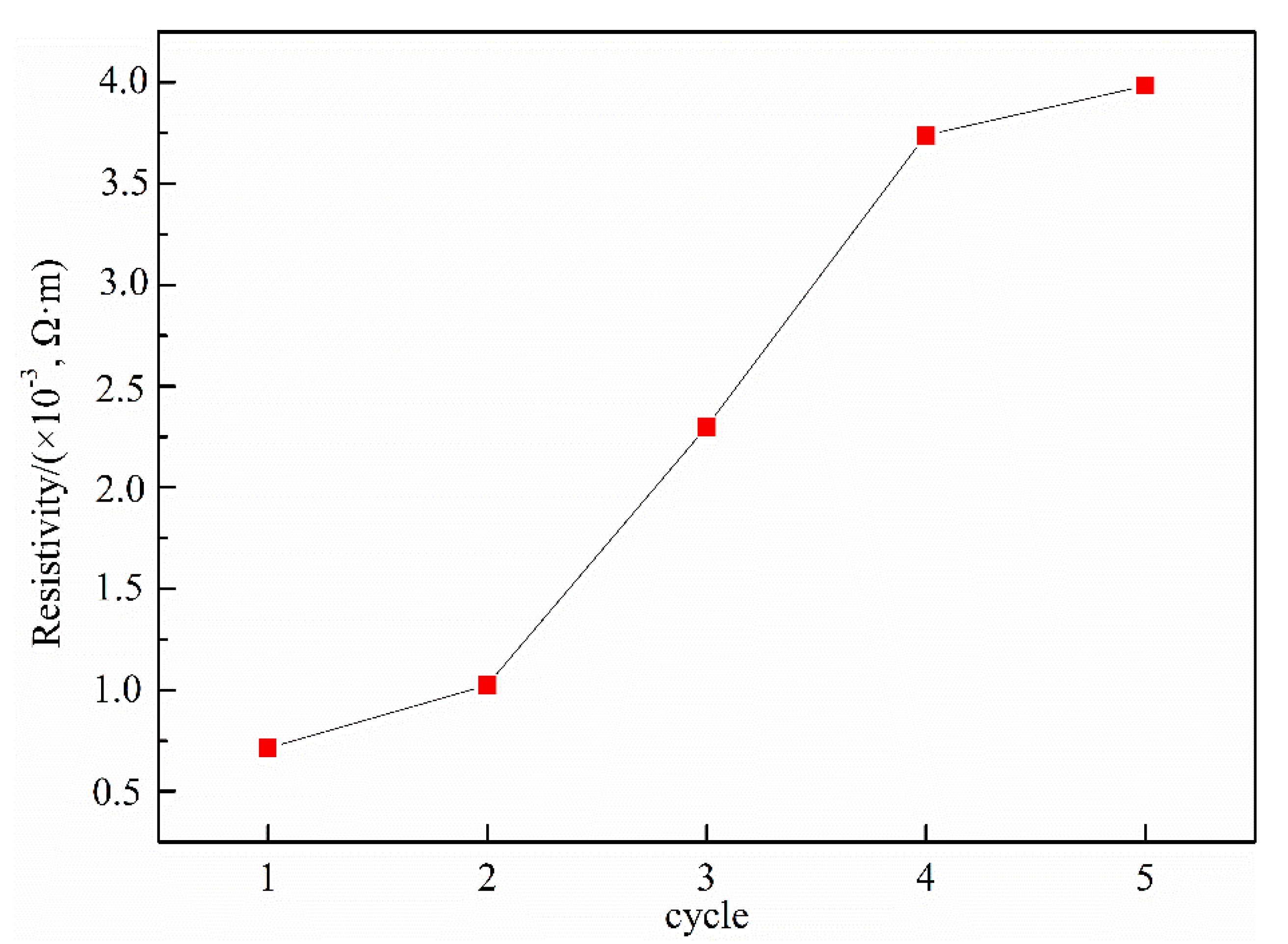
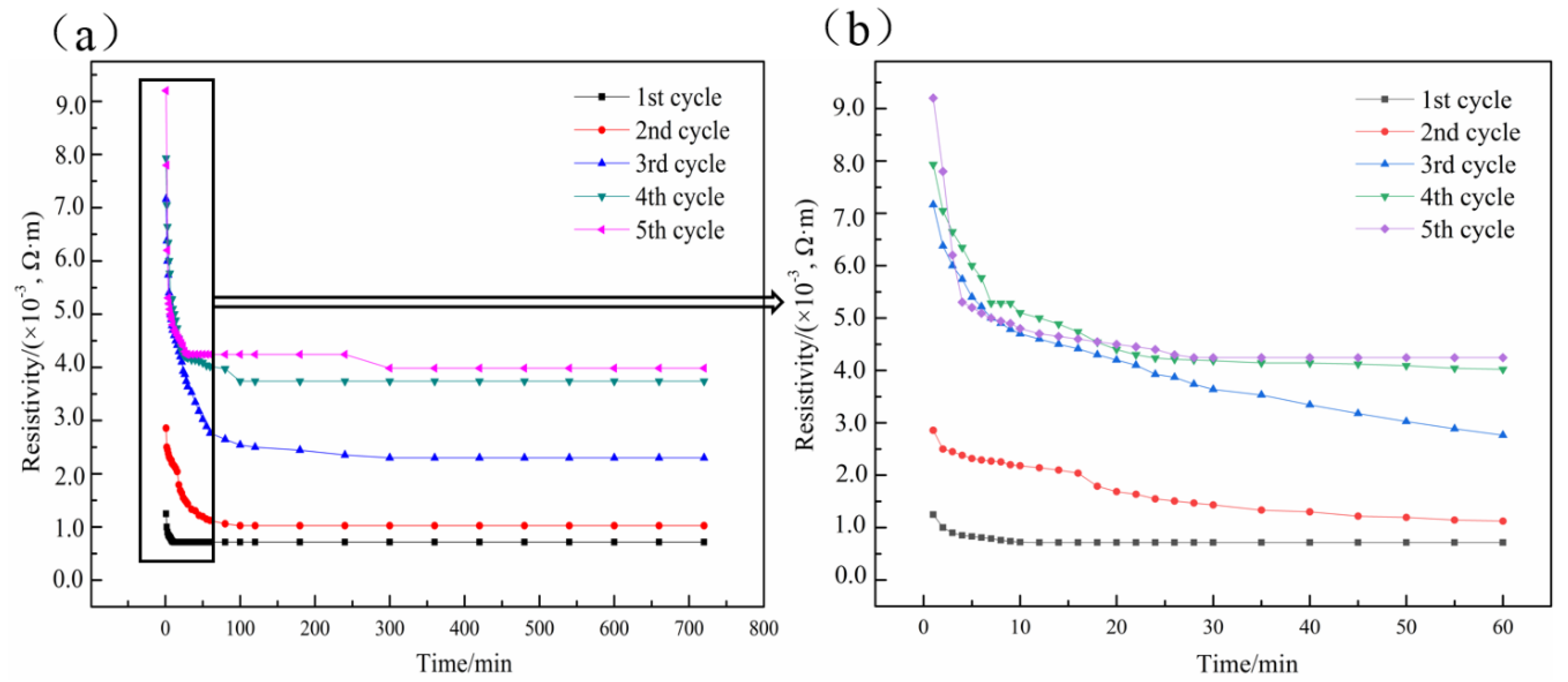
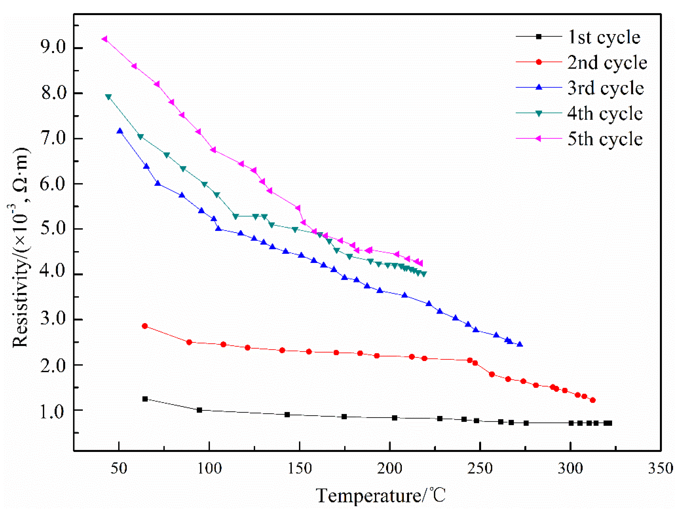
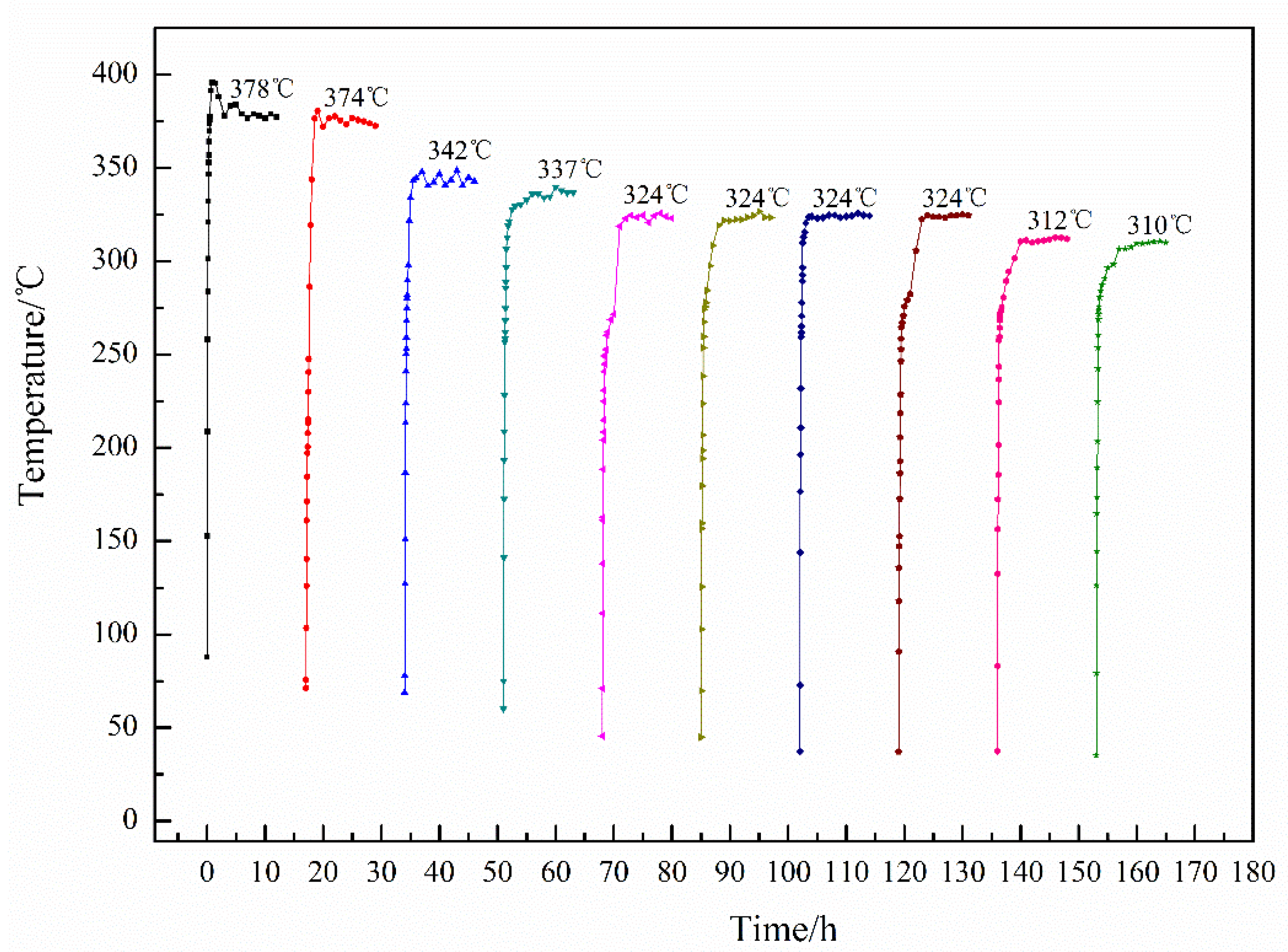
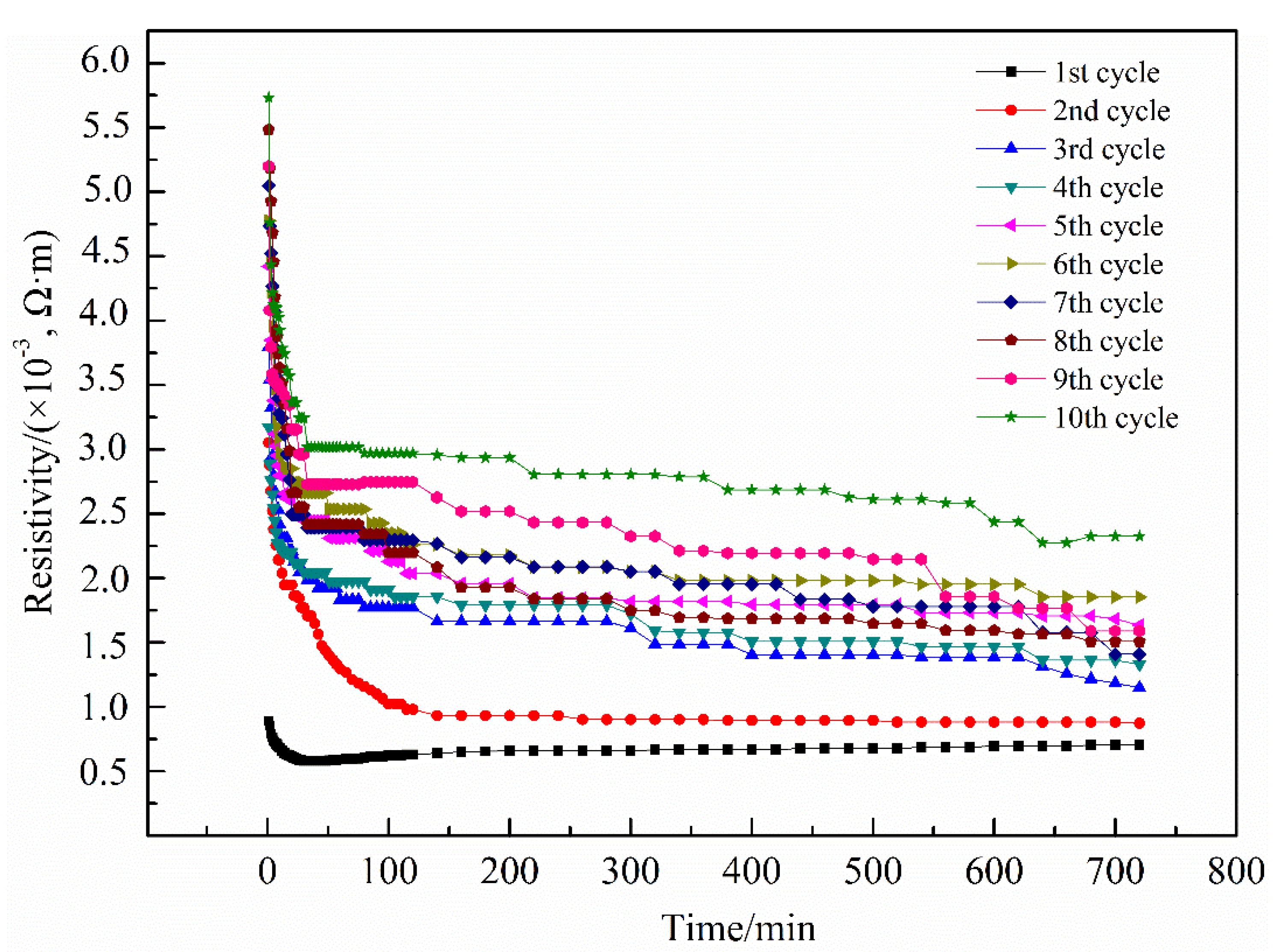
The resistivity of electrical-heating coating rises and the available heating temperature declines during cyclic electrification tests. This is attributed to the increased pores, expanded micro-cracks, and re-oxidized TiO2–x.
(3)
After hydrogen heat treatment, Ti3O5 of the electrical-heating coating increases obviously. The available heating temperature and the stability of coating resistivity are significantly improved.

Author Contributions

Conceptualization, X.L., K.Y. and C.D.; methodology, X.L., Y.Z. and K.Y.; software, X.L. and Y.Z.; validation, X.L., K.Y. and D.W.; formal analysis, X.L. and D.W.; investigation, Y.Z.; resources, K.Y. and C.D.; data curation, X.L. and Y.Z.; writing—original draft preparation, X.L.; writing—review and editing, K.Y.; visualization, X.L. and K.Y.; supervision, C.D.; project administration, K.Y. and D.W.; funding acquisition, K.Y. and C.D. All authors have read and agreed to the published version of the manuscript.

Funding

This research was funded by Pearl River S & T Nova Program of Guangzhou (201710010130), GDAS Project of Science and Technology Development (2017GDASCX-0111), Science and Technology Planning Project of Guangdong Province (2017A070701027, 2014B070705007), National Key R & D Program of China (2018YFB1502600), Science and Technology Innovation Platform Project of Guangdong Academy of Sciences (2019GDASYL-0402004).

Conflicts of Interest

The authors declare no conflicts of interest in this paper. The funders had no role in the design of the study; in the collection, analyses, or interpretation of data; in the writing of the manuscript, or in the decision to publish the results.

References

  1. Jang, H.-S.; Jeon, S.-K.; Nahm, S.-H. The manufacture of a transparent film heater by spinning multi-walled carbon nanotubes. Carbon 2011, 49, 111–116. [Google Scholar] [CrossRef]
  2. Cheng, C.; Ke, K.-C.; Yang, S.-Y. Application of graphene–polymer composite heaters in gas-assisted micro hot embossing. RSC Adv. 2017, 7, 6336–6344. [Google Scholar] [CrossRef] [Green Version]
  3. Heinz, C.-N.; Luigi, V.; Andre, S. Epoxy/MWCNT Composite as Temperature Sensor and Electrical Heating Element. IEEE Trans. Nanotechnol. 2011, 10, 688–693. [Google Scholar] [CrossRef]
  4. Sui, D.; Huang, Y.; Huang, L.; Liang, J.; Ma, Y.; Chen, Y. Flexible and Transparent Electrothermal Film Heaters Based on Graphene Materials. Small 2011, 7, 3186–3192. [Google Scholar] [CrossRef]
  5. Zhang, M.-C.; Wang, C.-Y.; Liang, X.-P.; Yin, Z.; Xia, K.; Wang, H.; Jian, M.; Zhang, Y. Weft-Knitted Fabric for a Highly Stretchable and Low-Voltage Wearable Heater. Adv. Electron. Mater. 2017, 3. [Google Scholar] [CrossRef]
  6. Li, D.-Q.; Tang, B.; Lu, X.; Li, Q.; Chen, W.; Dong, X.; Wang, J.; Wang, X. Simultaneous PAN Carbonization and Ceramic Sintering for Fabricating Carbon Fiber-Ceramic Composite Heaters. Appl. Sci. 2019, 9, 4945. [Google Scholar] [CrossRef] [Green Version]
  7. Prudenziati, M.; Gualtieri, M.L. Electrical properties of thermally sprayed Ni- and Ni20Cr-based resistors. J. Therm. Spray Technol. 2008, 17, 385–394. [Google Scholar] [CrossRef]
  8. Gadow, R.; Killinger, A.; Li, C. Product Development with Thermally Sprayed Functional Coatings on Glass and Glassceramics Substrates. Int. J. Appl. Ceram. Technol. 2005, 2, 493–503. [Google Scholar] [CrossRef]
  9. Prudenziatji, M. Development and the Implementation of High-Temperature Reliable Heaters in Plasma Spray Technology. J. Therm. Spray Technol. 2008, 17, 234–243. [Google Scholar] [CrossRef]
  10. Frenck, H.-J.; Kulisch, W.; Kuhr, M.; Kassing, R. Deposition of TiO2 thin films by plasma-enhanced decomposition of tetraisopropyltitanate. Thin Solid Film. 1991, 201, 327–335. [Google Scholar] [CrossRef]
  11. Killinger, A.; Gadow, R. Thermally Sprayed Coating Composites for Film Heating Devices. Adv. Sci. Technol. 2006, 45, 1230–1239. [Google Scholar] [CrossRef]
  12. Apkaryan, A.-S.; Khristyukov, V.-G.; Smirnov, G.-V. Heat insulation of high-temperature heating units for ceramic production. Glass Ceram. 2010, 67, 52–55. [Google Scholar] [CrossRef]
  13. Akani, A.; Suryanarayanau, R.; Brun, G. Influence of Process Parameters on the Electrical Properties of Plasma-Sprayed Silicon. J. Appl. Phys. 1986, 60, 457–459. [Google Scholar] [CrossRef]
  14. Liu, H.; Ma, Q.; Liu, W. Mechanical and oxidation resistance properties of 3d carbon fiber-reinforced mullite matrix composites prepared by sol–gel process. Ceram. Int. 2014, 40, 7203–7212. [Google Scholar] [CrossRef]
  15. Liang, Y.-H.; Zhou, B.-M.; Li, N.; Liu, L.; Xu, Z.; Li, F.; Li, J.; Mai, W.; Qian, X.; Wu, N. Enhanced dye photocatalysis and recycling abilities of semi-wrapped TiO2@carbon nanofibers formed via foaming agent driving. Ceram. Int. 2018, 44, 1711–1718. [Google Scholar] [CrossRef]
  16. Ariza-Tarazona, M.-C.; Villarreal-Chiu, J.-F.; Barbieri, V.; Siligardi, C.; Cedillo-González, E.I. New strategy for microplastic degradation: Green photocatalysis using a protein-based porous N-TiO2 semiconductor. Ceram. Int. 2019, 45, 9618–9624. [Google Scholar] [CrossRef]
  17. Lv, X.; Wang, T.-H.; Jiang, W. Preparation of Ag@AgCl/g-C3N4/TiO2 porous ceramic films with enhanced photocatalysis performance and self-cleaning effect. Ceram. Int. 2018, 44, 9326–9337. [Google Scholar] [CrossRef]
  18. Shi, J.-B.; Chen, G.-Q.; Zeng, G.-M.; Chen, A.; He, K.; Huang, Z.; Hu, L.; Zeng, J.; Wu, J.; Liu, W. Hydrothermal synthesis of graphene wrapped Fe-doped TiO2 nanospheres with high photocatalysis performance. Ceram. Int. 2018, 44, 7473–7480. [Google Scholar] [CrossRef]
  19. Roman, J.; Lech, P.; Francine, R.; Kozerski, S.; Petit, F. Characterization of mechanical properties of suspension plasma sprayed TiO2 coatings using scratch test. Surf. Coat. Technol. 2008, 202, 2644–2653. [Google Scholar] [CrossRef]
  20. Branland, N.; Meillot, E.; Fauchais, P.; Vaedelle, A.; Gitzhofer, F.; Boulos, M. Relationships between Microstructure and Electrical Properties of RF and DC Plasma-Sprayed Titania Coatings. J. Therm. Spray Technol. 2006, 15, 53–62. [Google Scholar] [CrossRef]
  21. Keshuukh, H.-P.; Shinde, P.-S.; Patil, P.-S. Structural, Optical and Electrical Characterization of Spray-deposited TiO2 Thin Films. Mater. Sci. Eng. B 2006, 130, 220–227. [Google Scholar] [CrossRef]
  22. Toma, F.-L.; Scheitz, S.; Puschmann, R.; Berger, L.-M. Development of ceramic heating elements produced by thermal spray technology. In Proceedings of the International Thermal Spray Conference, Dusseldorf, Germany, 27–29 September 2011; DVS Publishing House: Hamburg, Germany, 2012. [Google Scholar]
  23. Bobzin, K.; Oete, M.; Knoch, M.A.; Alkhasli, I. Temperature distribution on thermally sprayed heating conductor coatings. IOP Conf. Ser. Mater. Sci. Eng. 2019. [Google Scholar] [CrossRef]
  24. Culha, O.; Celik, E.; Azem, N.-F.-A.; Birlik, I.; Toparli, M.; Turk, A. Microstructural, thermal and mechanical properties of HVOF sprayed Ni-Al-based bond coatings on stainless steel substrate. J. Mater. Process. Technol. 2008, 204, 221–230. [Google Scholar] [CrossRef]
  25. Toma, F.-L.; Scheitz, S.; Berger, L.-M.; Sauchuk, V.; Kusnezoff, M.; Thiele, S. Comparative study of the electrical properties and characteristics of thermally sprayed alumina and spinel coatings. J. Therm. Spray Technol. 2011, 20, 195–204. [Google Scholar] [CrossRef]
  26. Lee, C. Photocatalytic properties of nano-structured TiO2 plasma sprayed coating. Surf. Coat. Technol. 2003, 173, 192–200. [Google Scholar] [CrossRef]
  27. Palmer, R.-A.; Doan, T.-M.; Lloyd, P.-G.; Jarvis, B.L.; Ahmed, N.U. Reduction of TiO2 with hydrogen plasma. Plasma Chem. Plasma Process. 2002, 22, 335–349. [Google Scholar] [CrossRef]
  28. Floristan, M.; Fontarnau, R.; Killinger, A.; Gadow, R. Development of electrically conductive plasma sprayed coatings on glass ceramic substrates. Surf. Coat. Technol. 2010, 205, 1021–1028. [Google Scholar] [CrossRef]
  29. Song, J.-B.; Zhang, X.-F.; Deng, C.-M.; Deng, C.; Liu, M.; Zhou, K.; Tong, X. Research of in situ modified PS-PVD thermal barrier coating against CMAS (CaO-MgO-Al2O3-SiO2) corrosion. Ceram. Int. 2016, 42, 3163–3169. [Google Scholar] [CrossRef]
  30. Liu, X.-Z.; Deng, C.-M.; Deng, C.-G.; Liu, M.; Zhou, K. Mullite-modified ZrB2-MoSi2 coating for carbon/carbon composites to withstand long term ablation. Ceram. Int. 2018, 44, 4330–4337. [Google Scholar] [CrossRef]
  31. Zhang, X.F.; Zhou, K.S.; Deng, C.M.; Liu, M.; Deng, Z.Q.; Deng, C.G.; Song, J.B. Gas-deposition mechanisms of 7YSZ coating based on plasma spray-physical vapor deposition. J. Eur. Ceram. Soc. 2016, 36, 697–703. [Google Scholar] [CrossRef]
  32. Zhou, Y.-Z.; Liu, M.; Yang, K.; Zeng, W.; Song, J.-B.; Deng, C.-M.; Deng, C.-G. Microstructure and Property of MoSi2-30Al2O3 Electrothermal Coating Prepared by Atmospheric Plasma Spraying. J. Inorg. Mater. 2019, 34, 646–652. [Google Scholar] [CrossRef] [Green Version]
  33. Yao, J.; Shao, J.; He, H.; Fan, Z. Optical and electrical properties of TiOx thin films deposited by electron beam evaporation. Vacuum 2007, 81, 1023–1028. [Google Scholar] [CrossRef]
  34. Cronemeyer, D.-C. Electrical and Optical Properties of Rutile Single Crystals. Phys. Rev. 1952, 87, 876–886. [Google Scholar] [CrossRef]
  35. Akira, O.-M.; Masayuki, I.; Yoshiaki, A.; Park, K.; Inuzuka, M.; Inoue, K.; Iwamoto, N. Electrical conductivity of plasma-sprayed titanium oxide (rutile) coatings. Thin Solid Film. 1991, 201, 1–8. [Google Scholar] [CrossRef]
  36. Bartholomew Robert, F.; Frankl, D.-R. Electrical Properties of Some Titanium Oxides. Phys. Rev. 1969, 187, 828–832. [Google Scholar] [CrossRef]
  37. Marezio, M.; Mcwhan, D.-B.; Dernier, P.-D.; Remeika, J.P. Structural Aspects of the Metal-insulator Transition in Ti4O7. J. Solid State Chem. 1973, 6, 213–221. [Google Scholar] [CrossRef]
Figure 1. Structure schematic diagram of the coating system sprayed on steel pipe.
Coatings 10 00177 g001
Figure 2. XRD patterns of TiO2-15MgAl2O4 powder and coating.
Coatings 10 00177 g002
Figure 3. SEM images of TiO2-15MgAl2O4 coating surface. (a) low magnification; (b) high magnification.
Coatings 10 00177 g003
Figure 4. Cross-sectional morphology of electrical-heating coating and EDS analysis.
Coatings 10 00177 g004
Figure 5. Backscatter electron imaging of TiO2-15MgAl2O4 coating and EDS analysis.
Coatings 10 00177 g005
Figure 6. Photograph of electrical-heating coating sample (a) and infrared thermal image of coating during the holding stage (b).
Coatings 10 00177 g006
Figure 7. Temperature–time curves of electrical-heating coating cyclic electrification tests.
Coatings 10 00177 g007
Figure 8. The coating resistivity of five electricity tests in the heat preservation stage.
Coatings 10 00177 g008
Figure 9. Resistivity–time curves of the coating cyclic electricity test (a) and graph of the corresponding heating stage 0-60min (b).
Coatings 10 00177 g009
Figure 10. The resistivity–temperature curves of coating in the heating stage.
Coatings 10 00177 g010
Figure 11. Cross-sectional morphology of electrical-heating coating after cyclic electricity test and EDS analysis.
Coatings 10 00177 g011
Figure 12. Temperature–time curves of the cyclic electrification test of heat-treated coatings.
Coatings 10 00177 g012
Figure 13. Resistivity–time curves of the cyclic electrification test of heat-treated coatings.
Coatings 10 00177 g013
Figure 14. XRD patterns of TiO2–15MgAl2O4 coating before and after hydrogen heat treatment.
Coatings 10 00177 g014
Table 1. Atmospheric plasma spraying parameters.
CoatingCurrent/AVoltage/VDistance/mmFlux of Ar L/minFlux of H2 L/minPowder Feed Rate g/min
Ni-Al6007011045825
MgAl2O46307511040933
TM1558079110411130

