Abstract
This article examines a wire coating technique using a viscoelastic Eyring–Powell fluid in which magnetohydrodynamic (MHD) flow, thermal transfer, and Joule heating effects are studied. Temperature-dependent, variable-viscosity models are used. Flexible-viscosity models which are temperature dependent are also considered. The interface of the thermal boundary layer which describe the flux and thermal convection phenomena, are evaluated by using a dominant numerical technique known as the fourth-order Runge–Kutta method. In particular, this article takes into account the impact of a permeable matrix which behaves like a dielectric in order to avoid heat dissipation. The effect of thermal generation is also explained, since it controls power. The novel effects for the numerous parameters which affect the velocity and temperature profiles on the wire coating process are investigated through graphs explained in detail. These include non-Newtonian, hydromagnetic, permeability, and heat source/sink effects. For validation purposes, the numerical scheme is also compared with a semi-numerical technique HAM and BVPh2 software, and found a closed agreement with the numerical results.
1. Introduction
Wire coating is an extrusion process that is usually used in the polymer manufacturing industries for the insulation of wires and cables. There are five units in a typical wire coating apparatus: a pay-off device, a wire preheater, an extruder equipped with a crosshead die, a cooling trough, and a take-up device. There are two classes of cross-sectional dies that are normally used in wire coating analysis—tubing-type die and pressure-type die. The pressure-type die closely resembles an annulus. Consequently, flow through this type of die has a similarity with the flow through the annular region formed by two coaxial cylinders, where the inner cylinder is moving in the axial direction while the outer cylinder is fixed. Different types of fluids are used for wire coating, depending on the geometry of the die, the fluid viscosity, and the temperature of the wire and molten polymer. Significant attention has been given to studying heat transfer analysis in Newtonian fluids. Numerous fluids such as air, water, and some oils are considered as non-Newtonian fluids in science and engineering technologies. In many circumstances, Newtonian fluid behavior may be complex. Therefore, a perturbed non-Newtonian model must be considered. Non-Newtonian behavior exists in liquid materials such as glue, paint, ketchup, custard, and blood. Because it has vast and significant applications in fluid mechanics and industries such as petroleum and chemical engineering, Non-Newtonian behavior has therefore gained the attention of researchers [1,2,3,4,5,6,7,8,9].
Ellahi et al. [10] discussed the non-Newtonian micro-polar liquid in blood movement through a composite stenosis. An Eyring–Powell fluid is a non-Newtonian fluid which was first presented in 1944 by Eyring and Powell. Many important features of an Eyring–Powell fluid are discussed by researchers [11,12,13,14,15]. Wire coating technique is very important in order to avoid injuries and decrease the losses that could be generated by machine oscillation. In manufacturing industries, various liquid polymers are used in the wire coating process. Melt polymer is poured over a wire and then the wire is pulled through the die that is covered by viscoelastic material. Three methods of wire coating are electro-static deposition, coaxial processing, and dipping. Compared to the first two, the dipping method of wire coating provides a stronger bond in the field, but is very slow. It contains a payoff device, a die and extruder device, a cooling device, a preheater, a straightener, a tester, a capstan, and a take-up reel. In this process, a bare wire is rolled over the payoff device and then goes through the straightener. Heat is then applied to the wire by a preheater and crosshead die, which has a conical die holding the liquid polymer where the wire is coated. The temperature of the hot, coated wire is reduced with a cooling device, after which it passes through a capstan and then a tester. Finally, the coated wire is puffed at the take-up reel. Many other researchers [16,17,18,19,20,21,22,23,24] have used various non-Newtonian materials for the wire coating process. In the magnetohydrodynamic (MHD) process, a magnetic field induces a current, which has a major effect on the motion of the fluid material. In recent years, the MHD process has been an attractive area for researchers because of its extensive use in industries such as magnetic-material and glass manufacturing. Many researchers [25,26,27,28,29,30,31,32,33] describe the MHD process as a current conducting liquid in the presence of an applied magnetic field.
Fluid flux through a permeable medium has a countless significance for scientists because of its broad scope in engineering technology. Some renowned permeable media are wood, carbonate rocks, and metal foams. Many researchers [34,35,36,37,38] have paid attention to permeable media. Currently, a thin permeable layer has domestic and industrial applications such as filters, batteries, fuel cells, and printing papers. The study of heat convection in non-Newtonian liquids has gained interest with time because of its application to different industries. Rehman and Nadeem [39] investigated heat convective analysis for multi-directional stagnation flow movement. Zeeshan, along with other researchers [40,41,42,43,44,45,46], studied the effect of thermal convection and hydromagnetic fluid flow. By studying all of the above articles, we found that a wire coating technique with an MHD process with a viscoelastic Eyring–Powell liquid as a coating substance has yet not been discussed. This paper discusses the procedure of a wire coating process with the impact of thermal generation and permeable media along with temperature-dependent flexible viscosity using Vogel’s and Reynolds’ models.
2. Modeling of Wire Coating
In Figure 1 the geometry of our problem is described. The parameters include the length of the pressure die , radius , and the saturated temperature due to incompressible viscoelastic Eyring–Powell material. As the temperature of the wire reaches the radius equals and the velocity becomes in the permeable medium. The wire is then pulled through the center length of the die in the static-pressure die. The out-flux fluid is acted upon simultaneously by uniform pressure gradient along the axis of the object and by a magnetic field of strength . The magnetic field is perpendicular to the direction of the Eyring–Powell incompressible fluid movement. To reduce or neglect the perturbation in the magnetic field, we used the Reynolds number in our problem. The wire and die have a common axis of symmetry, which was taken as a reference for the coordinated system. The appropriate expressions for the fluid velocity , the stress tensor , and the field temperature for this problem can be taken as:
The Cauchy stress tensor for the Eyring–Powell viscoelastic fluid is as
where denotes the viscosity, denotes the Cauchy stress tensor, denotes the velocity, and denotes the material constant. Equation (4) can be expressed as

Figure 1.
Geometry of the model problem.
The boundary conditions for the proposed model take the form of
Governing equations are given by
where is the velocity vector, represents the density, represents the temporal derivative, represents the rate of volumetric heat generation, and is the Joule dissipation term.
Applying Equations (1)–(3), the continuity of Equation (7) is identically satisfied and we get nonvanishing components of extra stress tensor as
Putting the velocity field and Equations (9)–(10) into Equation (8), we get
However, Equation (13) shows the flow due to the pressure gradient. When we leave the die, only dragging of the wire occurs. Therefore, the pressure gradient contributes nothing in the axial direction. So, Equation (14) takes the form
and the energy Equation (9) becomes
The dimensionless parameters are defined as:
Using these new variables in Equations (13) and (14) with Equation (6) and after removing asterisks, we get the following:
3. Temperature-Dependent Viscosity
Two basic models are used for temperature-dependent viscosity: Reynolds’ model and Vogel’s model, whose details are given below.
3.1. Reynolds’ Model
Here we use Reynolds’ model to explain temperature-dependent viscosity. The temperature-dependent viscosity for the Reynolds model can be expressed by the following relation:
This is applied for the variation of temperature-dependent viscosity, while is used for the viscosity parameter. Using nondimensional parameters,
After removing asterisks, we obtain nondimensional forms of momentum and energy equations along boundary conditions:
3.2. Vogel’s Model
In this case, we take temperature-dependent viscosity as
Applying expansions, we get
where are parameters of viscosity and
We obtain nondimensional equations of momentum and energy along boundary conditions after removing asterisks
4. Solution Procedure via Fourth-Order Runge–Kutta Method
Equations (23)–(26) in the case of Reynolds’ model, and Equations (30)–(33) for Vogel’s model are solved by using the fourth-order Runge–Kutta method along with shooting techniques. First, the above governing higher-order differential equations are converted into first-order ordinary differential equations.
Equations (23) and (25) can be written as
New variables are defined to convert higher-order ordinary differential equations into first order as
The boundary conditions given in Equations (23) and (25) are changed into initial conditions as
4.1. Reynolds’ Model
Equations (30) and (32) may be written after using Equation (36) as
The boundary conditions given in Equations (31) and (33) are changed into initial conditions as
4.2. Vogel’s Model
Using Equation (36) in Equations (30) and (32) we get the desired first-order differential equations as
along with transformed boundary conditions as
5. Validation of the Method
To validate our numerical solution, we made the following comparison, which proves the thoroughness of the proposed method. Our comparison is illustrated in Table 1 and Table 2. An excellent agreement is noted between the fourth-order Runge–Kutta method, the semi-numerical method HAM, and BVPh2.

Table 1.
Comparison of numerical, HAM, and BVPh2 methods for velocity profile.

Table 2.
Comparison of numerical, HAM, and BVPh2 methods for temperature profile.
6. Results and Discussion
This paper on wire coating considers the Eyring–Powell fluid. The method of coating a wire takes place in a die with a constant magnetic field and thermal generation effects in permeable media. Different measurable emerging parameters on velocity and temperature profiles are explained through graphs, including the non-Newtonian parameter viscosity parameter thermal generation parameters and for Reynolds’ and Vogel’s models respectively, permeable medium parameter , Brinkman number and the other parameter . In Figure 2, the geometry of the problem is explained. Figure 2 displays the Brinkman number over velocity distribution for the Reynolds’ model, and the velocity profile shows an increasing behavior as increases. In Figure 3, the results of the permeable medium parameter on the velocity distribution for Reynolds’ model were investigated when From this, the velocity profile decreases with increasing values of . By increasing the value of , the velocity curve shows a decreasing behavior, as predicted in Figure 4 for Reynolds’ model. In Figure 5, it is observed that by increasing the Brinkman number for Vogel’s model, the velocity profile increases while keeping some parameters fixed. Figure 6 represents the velocity profile for different values of . The velocity profiles increase with increasing . In Figure 7, it is shown that taking , the velocity profile rises with increasing for Vogel’s model. Figure 8 describes the inequality in temperature profile as a result of ε for uniform viscosity while keeping other parameters fixed. The velocity profile decreases as the value of increases. Figure 9 illustrates the output of Br on temperature distribution for uniform viscosity. When the value of increases, the velocity profile decreases. In Figure 10, the impact of on the temperature profile was observed, while keeping the viscosity and other parameters constant. Increasing the value of causes an increase in the velocity profile. In Figure 11 it is observed that the temperature curve increases by increasing for Reynolds’ model. A clear decline in the behavior of the velocity profile curve can be seen in Figure 12 as increases. In Figure 13, a decreasing behavior in temperature profile is observed by increasing Ω for Vogel’s model, keeping
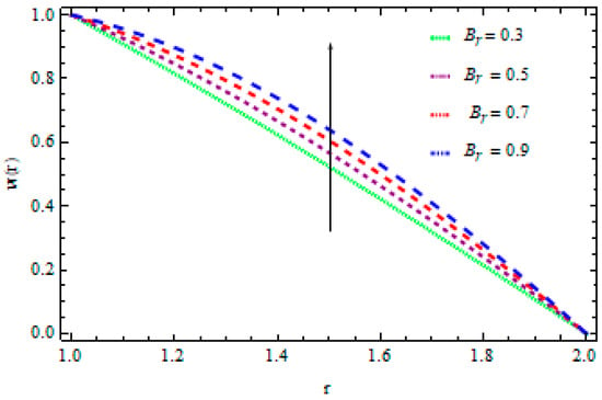
Figure 2.
The influence of on velocity distribution in case of Reynolds’ model when .
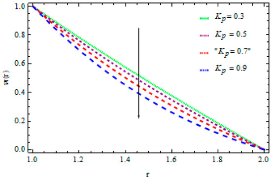
Figure 3.
The influence of on velocity distribution in case of Reynolds’ model when
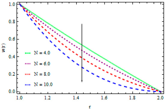
Figure 4.
The influence of on velocity distribution in case of Reynolds’ model when
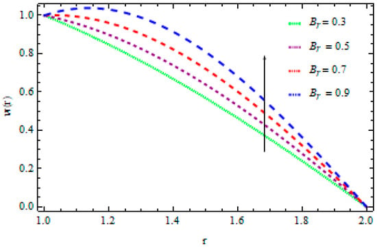
Figure 5.
The influence of on velocity distribution in case of Vogel’s model when
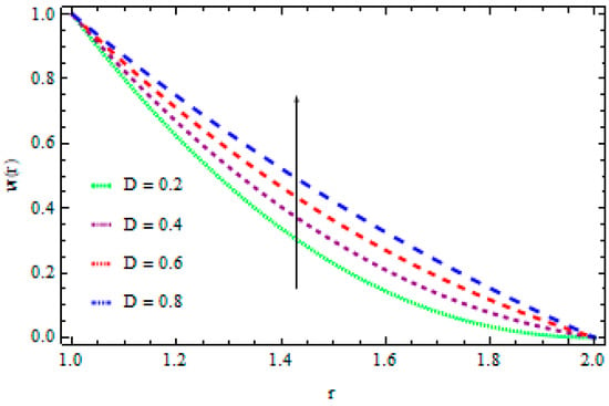
Figure 6.
The influence of on velocity distribution in case of Vogel’s model when
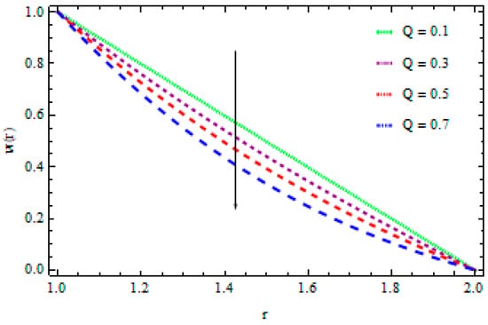
Figure 7.
The influence of
on velocity distribution for Vogel’s model when
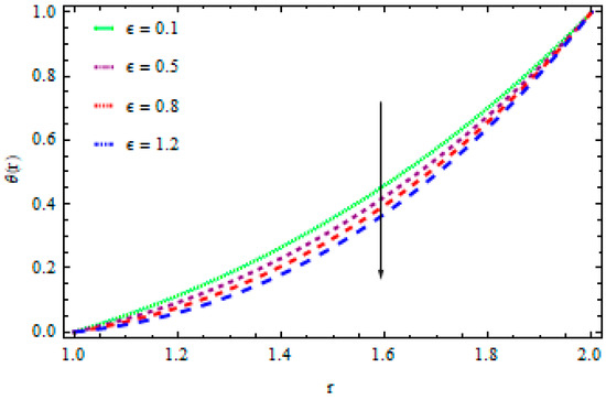
Figure 8.
The influence of on temperature when
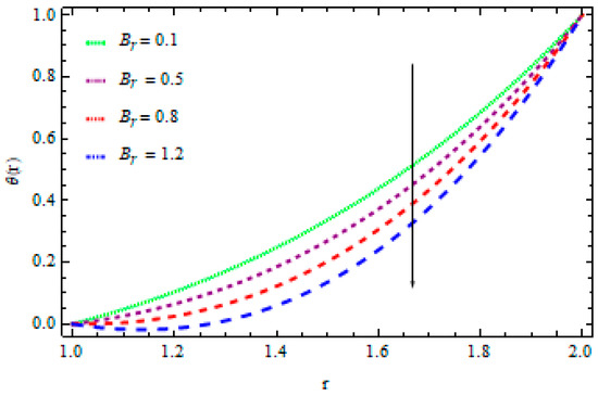
Figure 9.
The influence of on temperature when
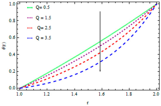
Figure 10.
The influence of on temperature when
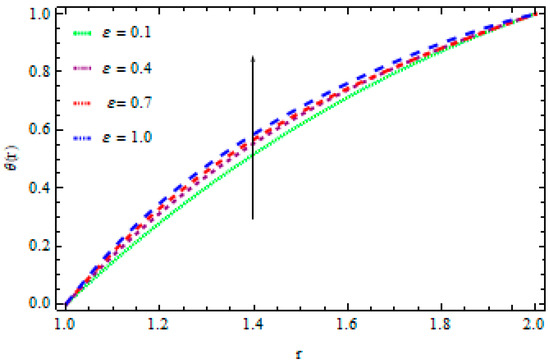
Figure 11.
The influence of on temperature distribution for Reynolds’ model when
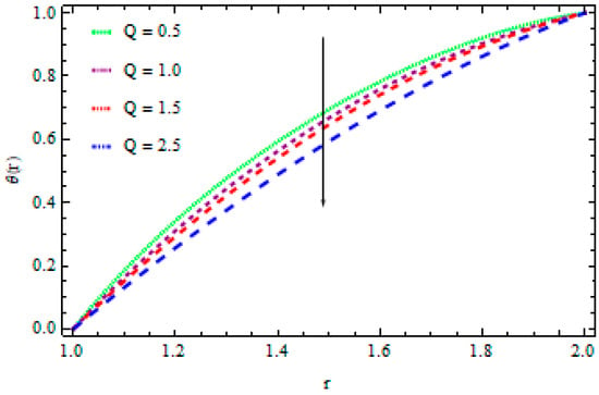
Figure 12.
The influence of on temperature distribution in case of Reynolds’ model when,
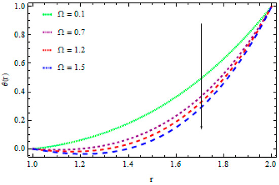
Figure 13.
The influence of on temperature distribution for Vogel’s model when
7. Concluding Remarks
In this article we investigated the effect of pertinent parameters such as hydromagnetic stream movement and heat transmission in a wire coating process using liquid polymer in a permeable medium along with a Joule heating effect and changeable viscosity. The wire is layered into a pressure-type die in order to interact with an Eyring–Powell liquid. A permeable matrix is used as a dielectric in order to enhance the heating/cooling process and to reduce the Joule heating effect during the flow and heat conduction process. The result is derived from the fourth-order Runge–Kutta method and sketched onto velocity and temperature profiles. The consequences are also verified by using the semi-numerical method techniques HAM and BVPh2. From these methods, a good agreement is found. The significant outcomes of the analysis presented in this research work are given below:
- An increase in fluid velocity behavior occurs as the values of increase, and a decrease in fluid velocity behavior occurs as the values of increase.
- The temperature distribution displays an increasing effect as the values of increase, while it shows a decreasing effect when the values of increase.
Author Contributions
Writing–Original Draft, Z.K. and H.U.R.; Conceptualization, S.I.; Methodology, S.N.; Software, I.K.; Validation, T.A.; Formal Analysis, W.K.; Writing–Review and Editing, Investigation, H.U.R.; Resources, S.I.; Data Curation, A.H.S; Visualization and Supervision, E.-S.M.S.; Project Administration and Funding, K.S.N. All authors have read and agreed to the published version of the manuscript.
Funding
This research was funded by DSR at Majmaah University under Project No (RGP-2019-3) and the Deanship of Scientific Research at King Saud University for its funding of this research through the Research Group Project No. RGP-160.
Acknowledgments
The authors extend their appreciation to the Deanship of Scientific Research at Majmaah University for funding this work under Project No (RGP-2019-3). The authors would also like to extend their sincere appreciation to the Deanship of Scientific Research at King Saud University for its funding of this research through the Research Group Project No. RGP-160.
Conflicts of Interest
The authors have no conflict of interest about this manuscript.
References
- Nadeem, S.; Ahmad, S.; Muhammad, N. Cattaneo–Christov flux in the flow of a viscoelastic fluid in the presence of Newtonian heating. J. Mol. Liq. 2017, 237, 180–184. [Google Scholar] [CrossRef]
- Ijaz, S.; Iqbal, Z.; Maraj, E.N.; Nadeem, S. Investigation of Cu–CuO/blood mediated transportation in stenosed artery with unique features for theoretical outcomes of hemodynamics. J. Mol. Liq. 2018, 254, 421–432. [Google Scholar] [CrossRef]
- Abbas, N.; Saleem, S.; Nadeem, S.; Alderremy, A.A.; Khan, A.U. On stagnation point fow of a micro polar nanofluid past a circular cylinder with velocity and thermal slip. Results Phys. 2018, 9, 1224–1232. [Google Scholar] [CrossRef]
- Ijaz, S.; Nadeem, S. Transportation of nanoparticles investigation as a drug agent to attenuate the atherosclerotic lesion under the wall properties impact Chaos. Solitons Fractals 2018, 112, 52–65. [Google Scholar] [CrossRef]
- Tabassum, R.; Mehmood, R.; Nadeem, S. Impact of viscosity variation and micro rotation on oblique transport of Cu–water fluid. J. Colloid Interface Sci. 2017, 501, 304–310. [Google Scholar] [CrossRef]
- Nadeem, S.; Sadaf, H. Exploration of single wall carbon nanotubes for the peristaltic motion in a curved channel with variable viscosity. J. Braz. Soc. Mech. Sci. Eng. 2017, 39, 117–125. [Google Scholar] [CrossRef]
- Shahzadi, I.; Sadaf, H.; Nadeem, S.; Saleem, A. Bio-mathematical analysis for the peristaltic flow of single wall carbon nanotubes under the impact of variable viscosity and wall properties. Comput. Methods Programs Biomed. 2017, 139, 137–147. [Google Scholar] [CrossRef]
- Ijaz, S.; Shahzadi, I.; Nadeem, S.; Saleem, A. A clot model examination: With impulsion of nanoparticles under influence of variable viscosity and slip effects. Commun. Theor. Phys. 2017, 68, 667. [Google Scholar] [CrossRef]
- Kumam, P.; Shah, Z.; Dawar, A.; Rasheed, H.U.; Islam, S. Entropy generation in MHD radiative flow of CNTs Casson nanofluid in rotating channels with heat source/sink. Math. Probl. Eng. 2019, 2019, 9158093. [Google Scholar] [CrossRef]
- Ellahi, R.; Rahman, S.U.; Gulzar, M.M.; Nadeem, S.; Vafai, K. A mathematical study of non-Newtonian micropolar fluid in arterial blood flow through composite stenosis. Appl. Math. Inf. Sci. 2014, 8, 1567–1573. [Google Scholar] [CrossRef]
- Hayat, T.; Nadeem, S. Aspects of developed heat and mass flux models on 3D flow of Eyring–Powell fluid. Results Phys. 2017, 7, 3910–3917. [Google Scholar] [CrossRef]
- Hayat, T.; Nadeem, S. Flow of 3D Eyring–Powell fluid by utilizing Cattaneo–Christov heat flux model and chemical processes over an exponentially stretching surface. Results Phys. 2018, 8, 397–403. [Google Scholar] [CrossRef]
- Ijaz, S.; Nadeem, S. A balloon model examination with impulsion of Cu-nanoparticles as drug agent through stenosed tapered elastic artery. J. Appl. Fluid Mech. 2017, 10, 1773–1783. [Google Scholar] [CrossRef]
- Ijaz, S.; Nadeem, S. A biomedical solicitation examination of nanoparticles as drug agents to minimize the hemodynamics of a stenotic channel. Eur. Phys. J. Plus 2017, 132, 448. [Google Scholar] [CrossRef]
- Saleem, S.; Nadeem, S.; Sandeep, N. A mathematical analysis of time dependent flow on a rotating cone in a rheological fluid. Propuls. Power Res. 2017, 6, 233–241. [Google Scholar] [CrossRef]
- Mitsoulis, E. Fluid flow and heat transfer in wire coating: A review. Adv. Polym. Technol. 1986, 6, 467–487. [Google Scholar] [CrossRef]
- Bagley, E.B.; Storey, S.H. Share rates and velocities of flow of polymers in wire-covering dies. Wire Wire Prod. 1963, 38, 1104. [Google Scholar]
- Khan, N.A.; Sultan, F.; Khan, N.A. Heat and mass transfer of thermophoretic MHD flow of Powell–Eyring fluid over a vertical stretching sheet in the presence of chemical reaction and Joule heating. Int. J. Chem. React. Eng. 2015, 13, 37–49. [Google Scholar] [CrossRef]
- Mahanthesh, B.; Gireesha, B.J.; Gorla, R.S.R. Unsteady three dimensional MHD flow of a nano Eyring–Powell fluid past a convectively heated stretching sheet in the presence of thermal radiation, viscous dissipation and Joule heating. J. Assoc. Arab Univ. Basic Appl. Sci. 2017, 23, 75–84. [Google Scholar] [CrossRef]
- Khana, N.; Sultan, F. Homogeneous–heterogeneous reactions in an Eyring–Powell fluid over a stretching sheet in a porous medium. Spec. Top. Rev. Porous Media 2016, 7, 15–25. [Google Scholar] [CrossRef]
- Hayata, T.; Aslam, N.; Rafq, M.; Alsaadi, F.E. Hall and Joule heating effects on peristaltic flow of Powell–Eyring liquid in an inclined symmetric channel. Results Phys. 2017, 7, 518–528. [Google Scholar] [CrossRef]
- Sadaf, H.; Nadeem, S. Analysis of combined convective and viscous dissipation effects for peristaltic flow of rabinowitsch fluid model. J. Bionic Eng. 2017, 14, 182–190. [Google Scholar] [CrossRef]
- Ahmed, A.; Nadeem, S. Biomathematical study of time-dependent flow of a Carreau nanofluid through inclined catheterized arteries with overlapping stenosis. J. Cent. South Univ. 2017, 24, 2725–2744. [Google Scholar] [CrossRef]
- Nadeem, S. Biomedical theoretical investigation of blood mediated nanoparticles (Ag–Al2O3/blood) impact on hemodynamics of overlapped stenotic artery. J. Mol. Liq. 2017, 24, 809–819. [Google Scholar]
- Ahmed, A.; Nadeem, S. Effects of magnetohydrodynamics and hybrid nanoparticles on a micropolar fluid with 6-types of stenosis. Results Phys. 2017, 7, 4130–4139. [Google Scholar] [CrossRef]
- Khan, Z.; Rasheed, H.U.; Alkanhal, T.A.; Ullah, M.; Khan, I.; Tlili, I. Effect of magnetic field and heat source on upper-convected-maxwell fluid in a porous channel. Open Phys. 2018, 16, 917–928. [Google Scholar] [CrossRef]
- Rehman, F.U.; Nadeem, S.; Rehman, H.U.; Haq, R.U. Thermo physical analysis for three-dimensional MHD stagnation-point flow of nano-material influenced by an exponential stretching surface. Results Phys. 2018, 8, 316–323. [Google Scholar] [CrossRef]
- Muhammad, N.; Nadeem, S.; Mustafa, M.T. Impact of magnetic dipole on a thermally stratified ferrofluid past a stretch-able surface. Proc. Inst. Mech. Eng. Part E J. Process Mech. Eng. 2018, 1, 1989–1996. [Google Scholar]
- Sadaf, H.; Akbar, M.U.; Nadeem, S. Induced magnetic field analysis for the peristaltic transport of non-Newtonian nanofluid in an annulus. Math. Comput. Simul. 2018, 148, 16–36. [Google Scholar] [CrossRef]
- Nadeem, S.; Ahmad, S.; Muhammad, N.; Mustafa, M.T. Chemically reactive species in the flow of a Maxwell fluid. Results Phys. 2017, 7, 2607–2613. [Google Scholar] [CrossRef]
- Khan, Z.; Rasheed, H.U.; Ullah, M.; Gul, T.; Jan, A. Analytical and numerical solutions of Oldroyd 8-constant fluid in double-layer optical fiber coating. J. Coat. Technol. Res. 2019, 16, 235–248. [Google Scholar] [CrossRef]
- Rehman, A.U.; Mehmood, R.; Nadeem, S. Entropy analysis of radioactive rotating nanofluid with thermal slip. Appl. Therm. Eng. 2017, 1122, 832–840. [Google Scholar] [CrossRef]
- Muhammad, N.; Nadeem, S. Ferrite nanoparticles Ni-ZnFe2O4, Mn-ZnFe2O4 and Fe2O4 in the flow of ferromagnetic nanofluid. Eur. Phys. J. Plus 2017, 132, 312–321. [Google Scholar] [CrossRef]
- Ijaza, S.; Nadeem, S. Consequences of blood mediated nano transportation as drug agent to attenuate the atherosclerotic lesions with permeability impacts. J. Mol. Liq. 2018, 262, 565–575. [Google Scholar] [CrossRef]
- Khan, Z.; Tairan, N.; Mashwani, W.K.; Rasheed, H.U.; Shah, H.; Khan, W. MHD and slip effect on two-immiscible third grade fluid on thin film flow over a vertical moving belt. Open Phys. 2019, 17, 575–586. [Google Scholar] [CrossRef]
- Rashid, M.; Shahzadi, I.; Nadeem, S. Corrugated walls analysis in micro channels through porous medium under electromagnetohydrodynamic (EMHD) effects. Results Phys. 2018, 9, 171–182. [Google Scholar] [CrossRef]
- Akbar, N.S. Double-diffusive natural convective peristaltic Prandtl flow in a porous channel saturated with a nanofluid. Heat Transf. Res. 2017, 48, 283–290. [Google Scholar] [CrossRef]
- Shahzadi, I.; Nadeem, S. Impinging of metallic nanoparticles along with the slip effects through a porous medium with MHD. J. Braz. Soc. Mech. Sci. Eng. 2017, 39, 2535–2560. [Google Scholar] [CrossRef]
- Rehman, F.U.; Nadeem, S. Heat transfer analysis for three-dimensional stagnation-point flow of water-based nanofluid over an exponentially stretching surface. J. Heat Transf. 2018, 140, 52401. [Google Scholar] [CrossRef]
- Khan, Z.; Rasheed, H.U.; Tlili, I.; Khan, I.; Abbas, T. Runge-Kutta 4th-order method analysis for viscoelastic Oldroyd 8-constant fuid used as coating material for wire with temperature dependent viscosity. Sci. Rep. 2018, 8, 14504. [Google Scholar] [CrossRef]
- Zeeshan, K.; Waqar, A.K.; Haroon Ur, R.; Ilyas, K.; Kottakkaran, S.N. Melting flow in wire coating of a third-grade fluid over a die using Reynolds’ and Vogel’s models with non-linear thermal radiation and joule heating. Materials 2019, 12, 3074. [Google Scholar] [CrossRef]
- Zeeshan, K.; Haroon Ur, R.; Alharbi, S.O.; Ilyas, K.; Tariq, A.; Dennis, L.C.C. Manufacturing of double layer optical fiber coating using phan-thien-tanner fluid as coating material. Coatings 2019, 9, 147. [Google Scholar] [CrossRef]
- Haroon Ur, R.; Zeeshan, K.; Saeed, I.; Ilyas, K.; Juan, L.G.G.; Waris, K. Investigation of two-dimensional viscoelastic fluid with nonuniform heat generation over permeable stretching sheet with slip condition. Complexity 2019, 2019, 3121896. [Google Scholar] [CrossRef]
- Zeeshan, K.; Muhammad, A.K.; Saeed, I.; Bilal, J.; Fawad, H.; Haroon Ur, R.; Waris, K. Analysis of magneto-hydrodynamics flow and heat transfer of a viscoelastic fluid through porous medium in wire coating analysis. Mathematics 2017, 5, 27. [Google Scholar] [CrossRef]
- Zeeshan, K.; Rehan, A.S.; Saeed, I.; Hamid, J.; Bilal, J.; Haroon Ur, R.; Aurangzeeb, K. MHD flow and heat transfer analysis in the wire coating process using elastic-viscous. Coatings 2017, 7, 15. [Google Scholar] [CrossRef]
- Haroon Ur, R.; Zeeshan, K.; Ilyas, K.; Dennis, L.C.C.; Kottakkaran, S.N. Numerical and analytical investigation of an unsteady thin film nanofluid flow over an angular surface. Processes 2019, 7, 486. [Google Scholar] [CrossRef]
© 2020 by the authors. Licensee MDPI, Basel, Switzerland. This article is an open access article distributed under the terms and conditions of the Creative Commons Attribution (CC BY) license (http://creativecommons.org/licenses/by/4.0/).