Anodic Protection Assessment Using Alumina-Forming Alloys in Chloride Molten Salt for CSP Plants


Abstract
1. Introduction
2. Anodic Protection in Chloride Molten Salts
3. Materials and Methods
4. Results and Discussion
5. Conclusions
Author Contributions
Funding
Acknowledgments
Conflicts of Interest
References
- Mehos, M.; Turchi, C.; Vidal, J.; Wagner, M.; Ma, Z.; Ho, C.; Kolb, W.; Andraka, C.; Kruizenga, A. Concentrating Solar Power Gen3 Demonstration Roadmap; Technical Report; NREL/TP-5500-67464; NREL: Golden, CO, USA, 2017.
- Gomez-Vidal, J.C.; Fernandez, A.G.; Tirawat, R.; Turchi, C.; Huddleston, W. Corrosion resistance of alumina-forming alloys against molten chlorides for energy production. I: Pre-oxidation treatment and isothermal corrosion tests. Sol. Energy Mater. Sol. Cells 2017, 166, 222–233. [Google Scholar] [CrossRef]
- Gomez-Vidal, J.C.; Fernandez, A.G.; Tirawat, R.; Turchi, C.; Huddleston, W. Corrosion resistance of alumina forming alloys against molten chlorides for energy production. II: Electrochemical impedance spectroscopy under thermal cycling conditions. Sol. Energy Mater. Sol. Cells 2017, 166, 234–245. [Google Scholar] [CrossRef]
- Vignarooban, K.; Xu, X.; Wang, K.; Molina, E.; Li, P.; Gervasio, D.; Kannan, A.M. Vapor pressure and corrosivity of ternary metal-chloride molten-salt based heat transfer fluids for use in concentrating solar power systems. Appl. Energy 2015, 159, 206–213. [Google Scholar] [CrossRef]
- Fernandez, A.G.; Cabeza, L.F. Corrosion evaluation of eutectic chloride molten salt for new generation of CSP plants. Part 1: Thermal treatment assessment. J. Energy Storage 2020, 27, 101125. [Google Scholar] [CrossRef]
- Brady, M.P. The development of alumina-forming austenitic stainless steels for high-temperature structural use. JOM 2008, 60, 12–18. [Google Scholar] [CrossRef]
- Indacochea, J.E.; Smith, J.L.; Litko, K.R.; Karell, E.J. Corrosion performance of ferrous and refractory metals in molten salts under reducing conditions. J. Mater. Res. 1999, 14, 1990–1995. [Google Scholar] [CrossRef]
- Garcia-Diaz, B.L.; Olson, L.; Martinez-Rodriguez, M.; Fuentes, R.; Colon-Mercado, H.; Gray, J. High temperature electrochemical engineering and clean energy systems. J. South Carol. Acad. Sci. 2016, 14, 11–14. [Google Scholar]
- Ding, W. Judith Gomez-Vidal, Alexander Bonk, Thomas Bauer, Molten chloride salts for next generation CSP plants: Electrolytical salt purification for reducing corrosive impurity level. Sol. Energy Mater. Sol. Cells 2019, 199, 8–15. [Google Scholar] [CrossRef]
- Ding, W.; Bonk, A.; Bauer, T. Corrosion behavior of metallic alloys in molten chloride salts for thermal energy storage in concentrated solar power plants—A review. Front. Chem. Sci. Eng. 2018, 12, 564–576. [Google Scholar] [CrossRef]
- Eom, H.-C.; Park, H.; Yoon, H.-S. Preparation of Anhydrous Magnesium Chloride from Magnesium Chloride Hexahydrate. Adv. Power Technol. 2010, 21, 125–130. [Google Scholar] [CrossRef]
- Huang, Q.; Lu, G.; Wang, J.; Yu, J. Thermal Decomposition Mechanisms of MgCl2·6H2O and MgCl2·H2O. J. Anal. Appl. Pyrolysis 2011, 91, 159–164. [Google Scholar] [CrossRef]
- Skar, R.A. Chemical and Electrochemical Characterisation of Oxide/Hydroxide Impurities in the Electrolyte for Magnesium Production. Ph.D. Thesis, Norwegian University of Science and Technology (NTNU), Trondheim, Norway, 2001. [Google Scholar]
- Ding, W.; Bonk, A.; Gussone, J.; Bauer, T. Electrochemical measurement of corrosive impurities in molten chlorides for thermal energy storage. J. Energy Storage 2018, 15, 408–414. [Google Scholar] [CrossRef]
- Kashani-Nejad, S. Oxides in the Dehydration of Magnesium Chloride Hexahydrate; McGill University: Montréal, QC, CA, 2005. [Google Scholar]
- Ding, W.; Shi, H.; Xiu, Y.; Bonk, A.; Weisenburger, A.; Jianu, A.; Bauer, T. Hot corrosion behavior of commercial alloys in thermal energy storage material of molten MgCl2/KCl/NaCl under inert atmosphere. Sol. Energy Mater. Sol. Cells 2018, 184, 22–30. [Google Scholar] [CrossRef]
- Gomez-Vidal, J.C.; Noel, J.; Weber, J. Corrosion evaluation of alloys and MCrAlX coatings in molten carbonates for thermal solar applications. Sol. Energy Mater. Sol. Cells 2016, 157, 517–525. [Google Scholar] [CrossRef]
- Audigié, P.; Bizien, N.; Baráibar, I.; Rodríguez, S.; Pastor, A.; Hernández, M.; Agüero, A. Aluminide slurry coatings for protection of ferritic steel in molten nitrate corrosion for concentrated solar power technology. AIP Conf. Proc. 2017, 1850, 0700021–0700028. [Google Scholar]
- Kruizenga, A.M. Corrosion Mechanisms in Chloride and Carbonate Salts; Sandia Report; SAND2012-7594; Sandia National Laboratories: Alburquerque, NM, USA, 2012.
- Hosoya, Y.; Terai, T.; Yoneoka, T.; Tanaka, S. Compatibility of structural materials with molten chloride mixture at high temperature. J. Nucl. Mater. 1997, 248, 348–353. [Google Scholar] [CrossRef]
- Macdonald, D. Reflections on the history of electrochemical impedance spectroscopy. Electrochim. Acta 2006, 51, 1376–1388. [Google Scholar] [CrossRef]
- Kisza, A. The capacitance of the diffuse layer of electric double layer of electrodes in molten salts. Electrochim. Acta 2006, 51, 2315–2321. [Google Scholar] [CrossRef]
- Orazem, M.E.; Tribollet, B. An integrated approach to electrochemical impedance spectroscopy. Electrochim. Acta 2008, 53, 7360–7366. [Google Scholar] [CrossRef]
- Zeng, C.L.; Wang, W.; Wu, W.T. Electrochemical impedance models for molten salt corrosion. Corros. Sci. 2001, 43, 787–801. [Google Scholar] [CrossRef]
- Fernández, A.G.; Rey, A.; Lasanta, I.; Mato, S.; Brady, M.; Perez, F.J. Corrosion of alumina-forming austenitic steel in molten nitrate salts by gravimetric analysis and impedance spectroscopy. Mater. Corros. 2014, 65, 267–275. [Google Scholar] [CrossRef]
- Gao, G.; Stott, F.H.; Dawson, J.L.; Farrell, D.M. Electrochemical monitoring of high temperature molten salt corrosion. Oxid. Met. 1990, 33, 79–94. [Google Scholar] [CrossRef]
- Rao, C.J.; Venkatesh, P.; Ningshen, S. Corrosion assessment of 9Cr-1Mo steel in molten LiCl-KCl eutectic salt by electrochemical methods. J. Nucl. Mater. 2019, 514, 114–122. [Google Scholar] [CrossRef]
- Titz, J.; Wagner, G.H.; Lorenz, W.J. In situ EIS studies of localized corrosion processes in research and industrial practice. Electrochim. Acta 1992, 37, 2309–2320. [Google Scholar] [CrossRef]


| K (%) | Mg (%) | Na (%) | Mn (ppm) | SO4 (ppm) | Cl (%) | H2O (%) |
|---|---|---|---|---|---|---|
| 20.6 | 11.9 | 3.4 | 1.8 | 162 | 60 | 5 |
| Alloy | wt.% | |||||||||
|---|---|---|---|---|---|---|---|---|---|---|
| Zr | Mn | Cr | Nb | Cu | Ti | Ni | Al | Mo | Fe | |
| OC4 | - | - | 14 | 2.5 | 0.5 | - | 25 | 3.5 | 2 | Balance |
| OCT | 0.3 | - | 14 | 3 | - | 2 | 35 | 3 | - | Balance |
| OCI | - | 5 | 14 | 1 | 3 | - | 12 | 2.5 | - | Balance |
| Element | R3 (Ohm) | Q1 (F/s) | R5 (Ohm) | Q2 (F/s) | R7 (Ohm) | Error (%) | Equivalent Circuit |
|---|---|---|---|---|---|---|---|
| 1 h | 1.71 | 0.66 | 26.68 | 0.17 | 7.49 | 0.52 |  |
| 3 h | 1.45 | 0.26 | 1.11 | 0.19 | 63.94 | 0.41 | |
| Element | R1 (Ohm) | Q1 (F/s) | R2 (Ohm) | Q3 (F/s) | R3 (Ohm) |  | |
| 5 h | 1.44 | 0.18 | 17.83 | 0.19 | 19.48 | 0.38 |
| Element | R3 (Ohm) | Q1 (F/s) | R5 (Ohm) | Q2 (F/s) | R7 (Ohm) | Error (%) | Equivalent Circuit |
|---|---|---|---|---|---|---|---|
| 1 h | 1.37 | 1.04 | 10.2 | 0.34 | 3.17 | 0.65 |  |
| Element | R1 (Ohm) | Q1 (F/s) | R3 (Ohm) | R5 (Ohm) | W1 |  | |
| 3 h | 1.38 | 0.07 | 12.92 | 0.02 | 1.84 | 0.58 | |
| 5 h | 1.37 | 0.43 | 13.46 | 5.94 | 2.06 | 0.43 |
| Element | R3 (Ohm) | Q1 (F/s) | R5 (Ohm) | Q2 (F/s) | R7 (Ohm) | Error (%) | Equivalent Circuit |
|---|---|---|---|---|---|---|---|
| 1 h | 1.44 | 0.15 | 0.47e-9 | 0.26 | 44.38 | 0.45 |  |
| 3 h | 1.36 | 1.15 | 4.71 | 0.27 | 58.25 | 0.37 | |
| 5 h | 1.36 | 0.46 | 19.18 | 0.44 | 36.92 | 0.31 |
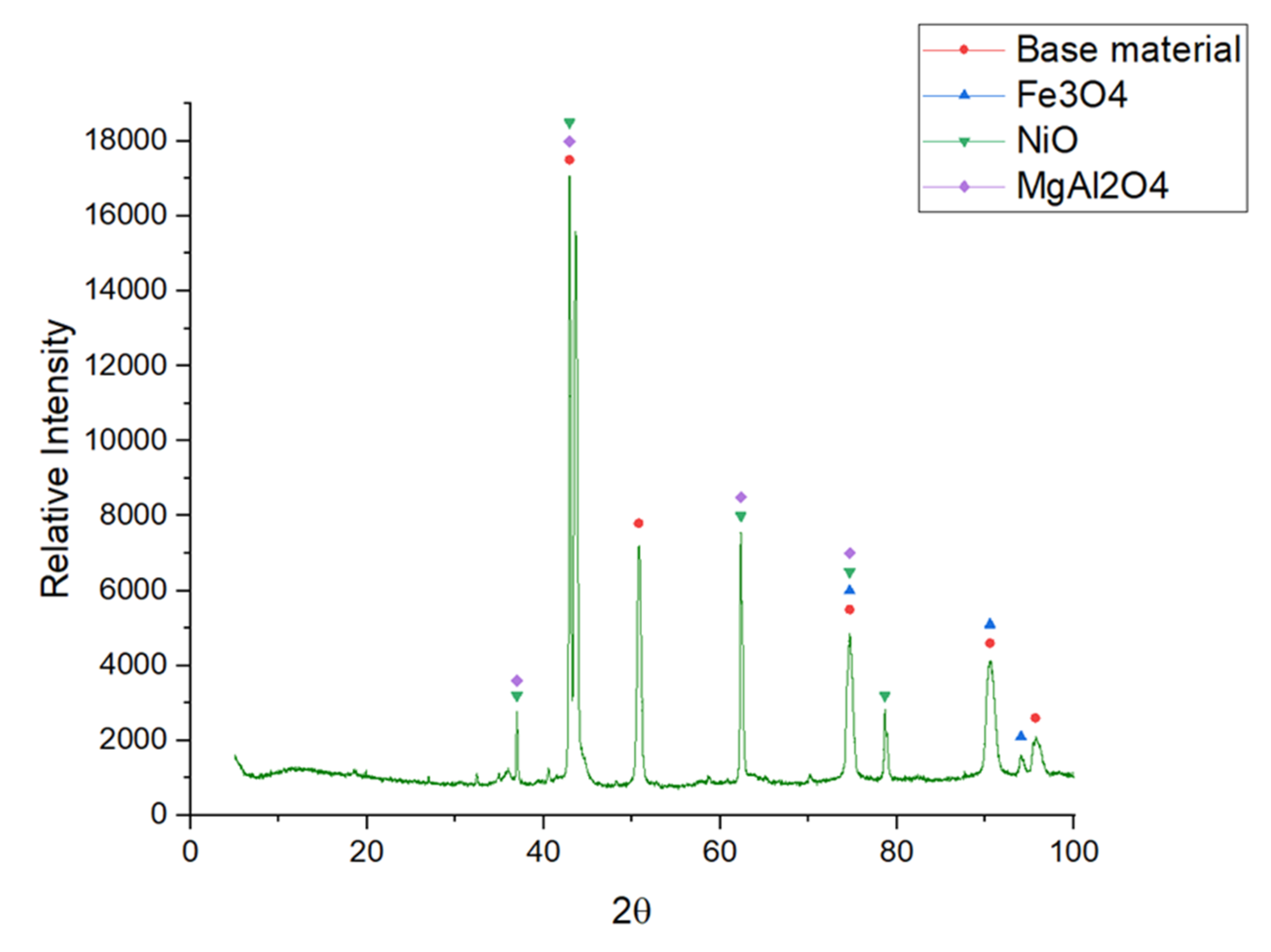
| Salt Mixture | Material | Corrosion Products | Reference Pattern |
|---|---|---|---|
| MgCl2/NaCl/KCl (55.1 wt.%–24.5 wt.%–20.4 wt.%) | OC4 | FeCr2O4 MgAl2O4 | 00-024-0511 00-033-0853 |
| OCI | Fe2O3 MgOHCl MgO | 01-089-0597 00-012-0120 01-087-0651 | |
| OCT | MgAl2O4 NiO Fe3O4 | 00-033-0853 03-065-6920 01-086-1353 |
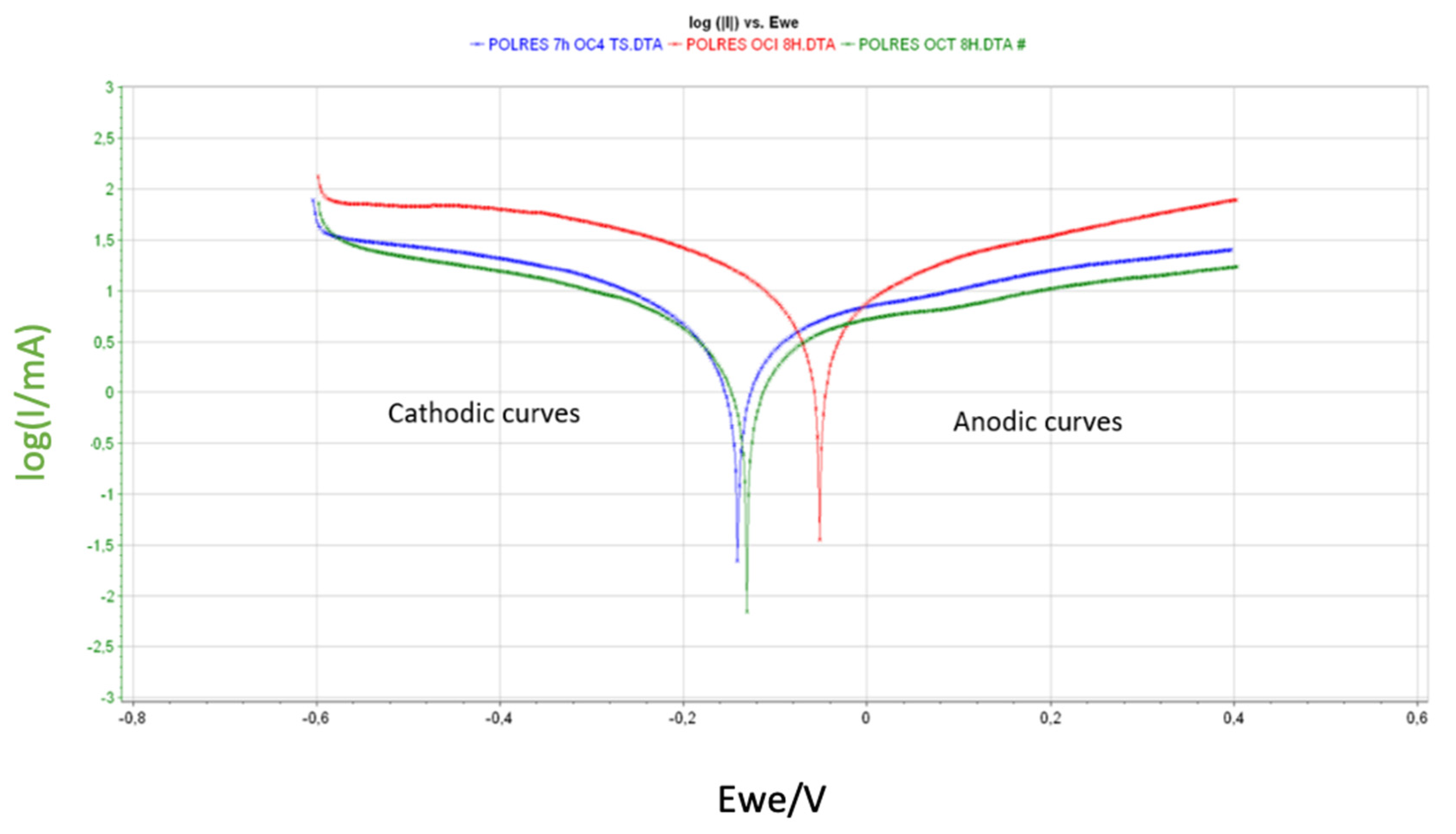
| Alloys | Ecorr (mV) | Icorr (mA) | βc (mV) | βa (mV) | A (cm2) | CR (mm/year) |
|---|---|---|---|---|---|---|
| OC4 | −140.79 | 4258.75 | 322.1 | 651 | 4.46 | 8.03 ± 0.64 |
| OCI | −52.59 | 11429.4 | 398.9 | 524.9 | 4.53 | 21.55 ± 0.89 |
| OCT | −131.86 | 3837.05 | 407 | 902.2 | 4.41 | 7.61 ± 0.55 |
© 2020 by the authors. Licensee MDPI, Basel, Switzerland. This article is an open access article distributed under the terms and conditions of the Creative Commons Attribution (CC BY) license (http://creativecommons.org/licenses/by/4.0/).
Share and Cite
Fernández, A.G.; Cabeza, L.F. Anodic Protection Assessment Using Alumina-Forming Alloys in Chloride Molten Salt for CSP Plants. Coatings 2020, 10, 138. https://doi.org/10.3390/coatings10020138
Fernández AG, Cabeza LF. Anodic Protection Assessment Using Alumina-Forming Alloys in Chloride Molten Salt for CSP Plants. Coatings. 2020; 10(2):138. https://doi.org/10.3390/coatings10020138
Chicago/Turabian StyleFernández, Angel G., and Luisa F. Cabeza. 2020. "Anodic Protection Assessment Using Alumina-Forming Alloys in Chloride Molten Salt for CSP Plants" Coatings 10, no. 2: 138. https://doi.org/10.3390/coatings10020138
APA StyleFernández, A. G., & Cabeza, L. F. (2020). Anodic Protection Assessment Using Alumina-Forming Alloys in Chloride Molten Salt for CSP Plants. Coatings, 10(2), 138. https://doi.org/10.3390/coatings10020138