Article

Reinforced Superhydrophobic Anti-Corrosion Epoxy Resin Coating by Fluorine–Silicon–Carbide Composites

1
School of Materials Science and Engineering, Xiangtan University, Xiangtan 411105, China
2
College of Nuclear Science and Technology, Beijing Normal University, Beijing 100875, China
*
Authors to whom correspondence should be addressed.
Coatings 2020, 10(12), 1244; https://doi.org/10.3390/coatings10121244
Submission received: 17 November 2020 / Revised: 14 December 2020 / Accepted: 15 December 2020 / Published: 17 December 2020
(This article belongs to the Special Issue Coatings for Corrosion Mitigation)

Abstract

:
SiC was modified by fluorine-containing organic substance 1H,1H,2H,2H-trifluoro-noctyltriethoxysilane (FAS) to change its hydrophilicity from hydrophilic to superhydrophobic nanoparticles, and the optimum conditions for hydrophobicity were effectively explored. Then, different content of fluorine-modified SiC (F–SiC) nanoparticles were added to the epoxy resin (EP) matrix to prepare composite coating samples. The results showed that the surface of SiC was modified by FAS to show superhydrophobicity, and the dispersion in EP was significantly improved. After adding F–SiC, the hydrophobicity, wear resistance and corrosion resistance of the coating were significantly improved. In addition, the corrosion resistance of the composite coating containing different contents of F–SiC was analyzed through electrochemical and salt spray tests. The results showed that the corrosion resistance of the coating was the best when the addition amount was 3 wt %. In general, the composite coating with 3 wt % F–SiC had the best overall performance. Compared with the EP coating, the water contact angle of 3 wt % F–SiC/EP composite coating was increased by 62.9%, the friction coefficient was reduced by 73.5%, and the corrosion current was reduced by three orders of magnitude. This study provides a new idea for the development of ultra-wear-resistant and anti-fouling heavy-duty coatings.

1. Introduction

Metal corrosion is one of the important factors causing huge economic losses around the world. The annual economic loss due to metal corrosion exceeds USD 100 billion, far exceeding the sum of natural disasters such as typhoons, floods and fires [1]. In addition, metal corrosion in engineering equipment may cause unsafe accidents due to the premature failure of structural materials [2]. Excessive heavy metal ions are released and diffused into water, soil and crops, causing serious pollution to the contemporary environment [3,4]. Therefore, it is very important to reduce the hazards of metal corrosion, and the research of adopting effective measures to slow down metal corrosion has become the focus of the research field in metal protection.
There are several ways to prevent metal corrosion for different engineering fields. At present, the main methods for metal protection include adding corrosion inhibitors [5], electrochemical protection methods [6], alloying treatment [7,8], electroplating spraying [9,10], and non-metallic coatings [11,12,13], etc. Corrosion inhibitors will accumulate adsorption film or insoluble substances on the metal surface, thereby changing the charge state and interface properties of the metal surface, accelerating the degree of polarization, forming a protective film, and minimizing corrosion micro-current. Three types of corrosion inhibitors (inorganic, organic and vapor phase) are developed according to the application requirement. However, because the corrosion inhibitor is toxic, excessive addition will cause severe pollution to the surrounding environment. For the alloying and electroplating spraying methods, the use in the construction environment is restricted by a complicated treating process. Non-metallic coatings have become the most popular metal protection method due to the advantages of simple construction, low cost and convenient cleaning. Among the non-metallic coatings, epoxy resin (EP) is the most widely used material in engineering fields. Although the epoxy resin has excellent corrosion resistance, high adhesion and a low price, the epoxy resin may contain hydrophilic groups such as –OH, –CHOOH and –NH2 to make the epoxy resin hydrophilic [14], and the liquids can maintain firm contact with the epoxy surface, thereby accelerating the corrosion processes. To solve these problems in epoxy resin coatings, a lot of research has been conducted to improve the mechanical property of epoxy resin and reduce the production of micropores. The composite of nanoparticles with epoxy resin has received widespread attention in the field of non-metallic coatings. The addition of nanomaterials such as SiO2 [15], SiC [16], TiO [17], Al2O3 [18], ZnO [19] graphene, graphene oxide, etc., can effectively increasing the anti-corrosion performance of epoxy resin coatings.
For some special application fields, such as marine cargo ships, warships, marine engineering, etc., the protective coatings require not only the corrosion resistance of the coating but also extremely high wear resistance and antifouling performance. It is well known that the SiC nanoparticle has excellent wear resistance, corrosion resistance, and excellent heat resistance [20,21,22], which can meet the requirements of super wear-resistant coatings [23]. In addition, the surface of SiC is rich in hydroxyl groups, and surface treatment can be an effective method to make it a hydrophobic material [24]. However, there are few reports on the use of SiC composites to enhance the performance of epoxy coatings. This is because the compatibility of SiC in epoxy resin is usually poor, and the higher surface energy of nano-sized SiC and strong hydrophilicity leads to severe particle agglomeration. Many methods have been tried to disperse SiC into EP. For example, samples containing 0.5, 1, 2 and 4 wt % of β-silicon carbide nanowhiskers and nanoparticles in epoxy resin were prepared using a high-intensity ultrasonic liquid processor and casting technique [25]. However, when the SiC fiber content increases, agglomeration occurs due to the interaction between the fillers. Therefore, a better dispersion method is worth studying. Kychkin studied the effect of ultra-fine silicon carbide powder on the performance of epoxy resin [26]. The study found that when adding 0.75 wt % silicon carbide, a 16% increase in flexural strength and a 5% increase in compressive elastic modulus were observed. Archana Nigrawal studied the mechanical properties of epoxy resin/nano-SiC composites and found that the bending performance increased with the increase in SiC weight percentage, and the best bending performance was obtained when the weight percentage of SiC increased to 2 wt %. However, when 3 wt % of SiC filler was added to EP, the bending performance of the composite material decreased instead [27]. Iijima studied the method of increasing the hydrophilic groups on the surface of SiC nanoparticles through reacting the unsaturated hydrocarbons with the azo radical initiator [28]. Huang introduced a new modifier, 1H, 1H, 2H, 2H-perfluorooctyltriethoxysilane (FAS) for the covalent functionalization of graphene, thereby improving the dispersion of graphene in organic matter, which provided us with an idea for modifying SiC and improving the dispersion of SiC in the organic matter [29]. Shang developed a SiC surface modification method using 3-aminopropyltriethoxysilane (KH550) and 3-mercaptopropyltrimethoxysilane (KH590) as initial modifiers to improve the hydrophobic properties of SiC powder [30].
Based on the above studies, the composite material of superhydrophobic modification SiC with EP is a useful additive for improving anti-corrosion performance, and much research on hydrophobically modified nanoparticles filled with epoxy resin has been carried out [31,32], however, there are not many studies on superhydrophobic SiC particles filled with epoxy resin. In this work, a superhydrophobic SiC was synthesized by chemically grafting FAS onto the surface of SiC, and then the superhydrophobic SiC was added to EP for producing SiC/EP composite material. Due to the grating of the organic molecule on the surface of SiC, the compatibility of nano-SiC with EP was largely improved. The introduction of superhydrophobic SiC greatly improved the wear resistance, corrosion resistance and hydrophobicity of the composite coating. On this basis, the performance of the composite coating was optimized, the performance under different addition levels was studied, and the optimized ratio was obtained.

2. Experimental

2.1. Materials

Nano-SiC (40 nm) and 1H,1H,2H,2H-Tridecafluoro-n-octyltriethoxysilane (>97%) were purchased from Aladdin Industrial Co., Ltd. (Shanghai, China). EP (CYD 014, epoxy equivalent is 0.12) and its curing agent (P54, active hydrogen equivalent is 327.86) were purchased from Baling Chemical (Yueyang, China) Co. The thinners used in the experiment were xylene and n-butanol, which were purchased from Aladdin Industrial Co., Ltd. (Shanghai, China) in a volume ratio of 4:6. Ultrapure water (specific resistance ≥ 18 MΩ·cm) was made in the laboratory, and absolute ethanol (analytical grade) and glacial acetic acid were purchased from Sinopharm Chemical Reagent Co., Ltd., China (Shanghai, China). Test substrates (Q235 steel sheets) were purchased from Biuged Laboratory Instruments Co., Ltd. (Guangzhou, China).

2.2. Preparation of Superhydrophobic Nano-SiC

The superhydrophobic modification of SiC was carried out by chemical grafting. Firstly, 0.4 g SiC was weighed and placed in a flask, then 100 mL of absolute ethanol was added and shaken for 30 min. At the same time, stirring was started until the end of the experiment. Then, the pH of the solution was adjusted to 4~5 by adding dropwise glacial acetic acid. A certain amount of FAS and 2 mL of water were added dropwise before the surface modification. Finally, F–SiC was prepared by heating in the water bath, stirring at 500 rpm for 2 h. The obtained superhydrophobic nano-SiC was washed and dried before adding to the epoxy coating.

2.3. Preparation of Epoxy Composite Coating

Before preparing the composite coating, the substrate was pretreated, including sanding, rust removal, oil removal and degreasing. The steps of preparing F–SiC/EP composite coating were as follows. First, a certain amount of F–SiC (1–5 wt %) and EP were mixed and stirred for 12 h. Then, the curing agent (P54) and diluent were added to the mixture. Subsequently, the thickness of the mixture was sprayed on the surface of the low-carbon steel sheet, and finally, the F–SiC/EP coating was cured at 80 °C for 1 h to obtain a coating with a thickness of 60 ± 5 μm.

2.4. Characterization

The morphology and physical structure were characterized by scanning electron microscope (SEM, ZEISS MERLIN Compact, Jena, Germany); The chemical structures of SiC before and after modification were characterized by Fourier-transform infrared spectroscopy (FTIR, Shanghai, China), X-ray diffraction (XRD, u1tima IV, Tokyo, Japan) and X-ray photoelectron spectroscopy (XPS, thermo Kalpha, Shanghai, China). The contact angle of water after hydrophobic modification was evaluated by a contact angle measuring instrument (DSA100, Hamburg, Germany), which uses the shape image analysis method: drop the droplet (10 μL) on the surface of the solid sample, obtain the shape image of the droplet through the microscope lens and the camera, and then use digital image processing and some algorithms to calculate the contact angle of the droplet in the image. The wear resistance of the coating was evaluated by a friction and wear tester (UMT-2, Campbell, Camden, NJ, USA). In the wear resistance test, the friction ball was a 440-carbon steel ball, which was loaded with a force of 2 N in the vertical direction, and rubbed back and forth at the speed of 40 mm/s in a stroke of 10 mm. The salt spray resistance of the coating was tested in a neutral salt spray test chamber (BGD-887) according to the ISO 9227-2017 standard [33]. An electrochemical workstation (zahner PP211, Kronach, Germany) was used to detect the corrosion resistance of the coating.

3. Results

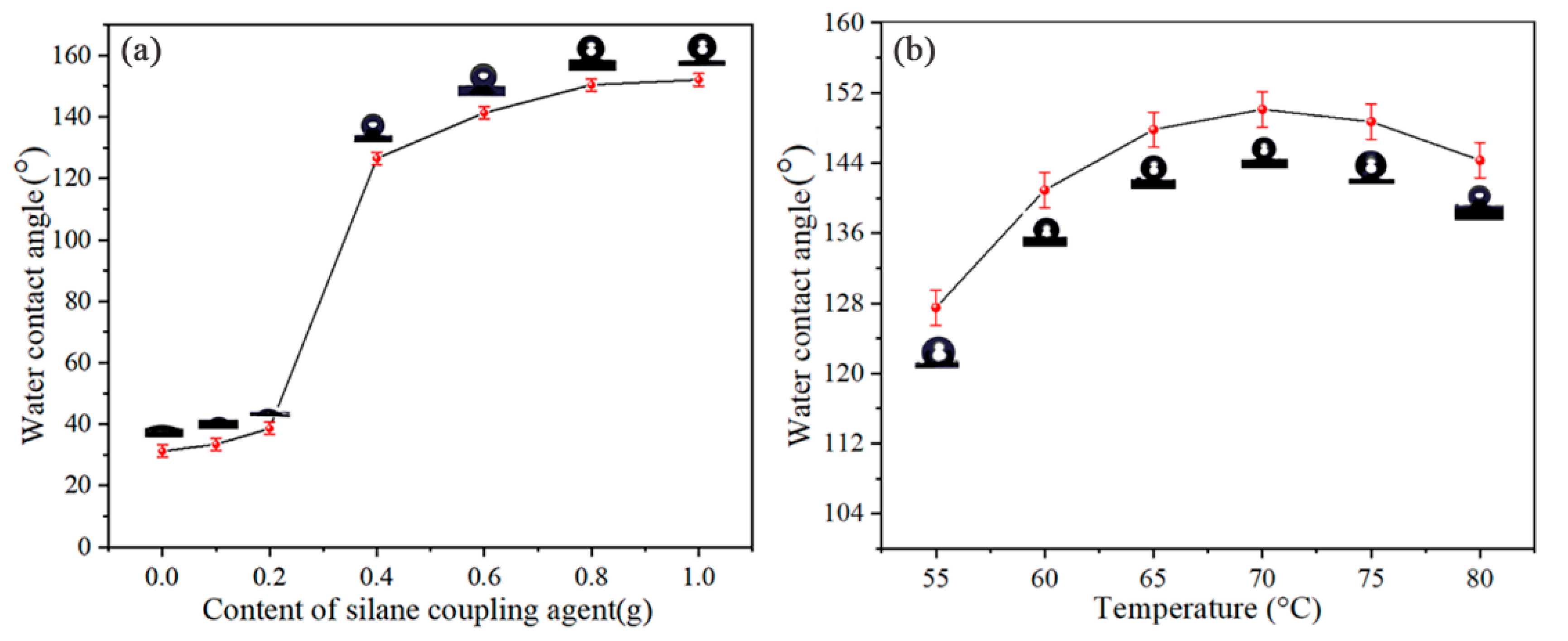
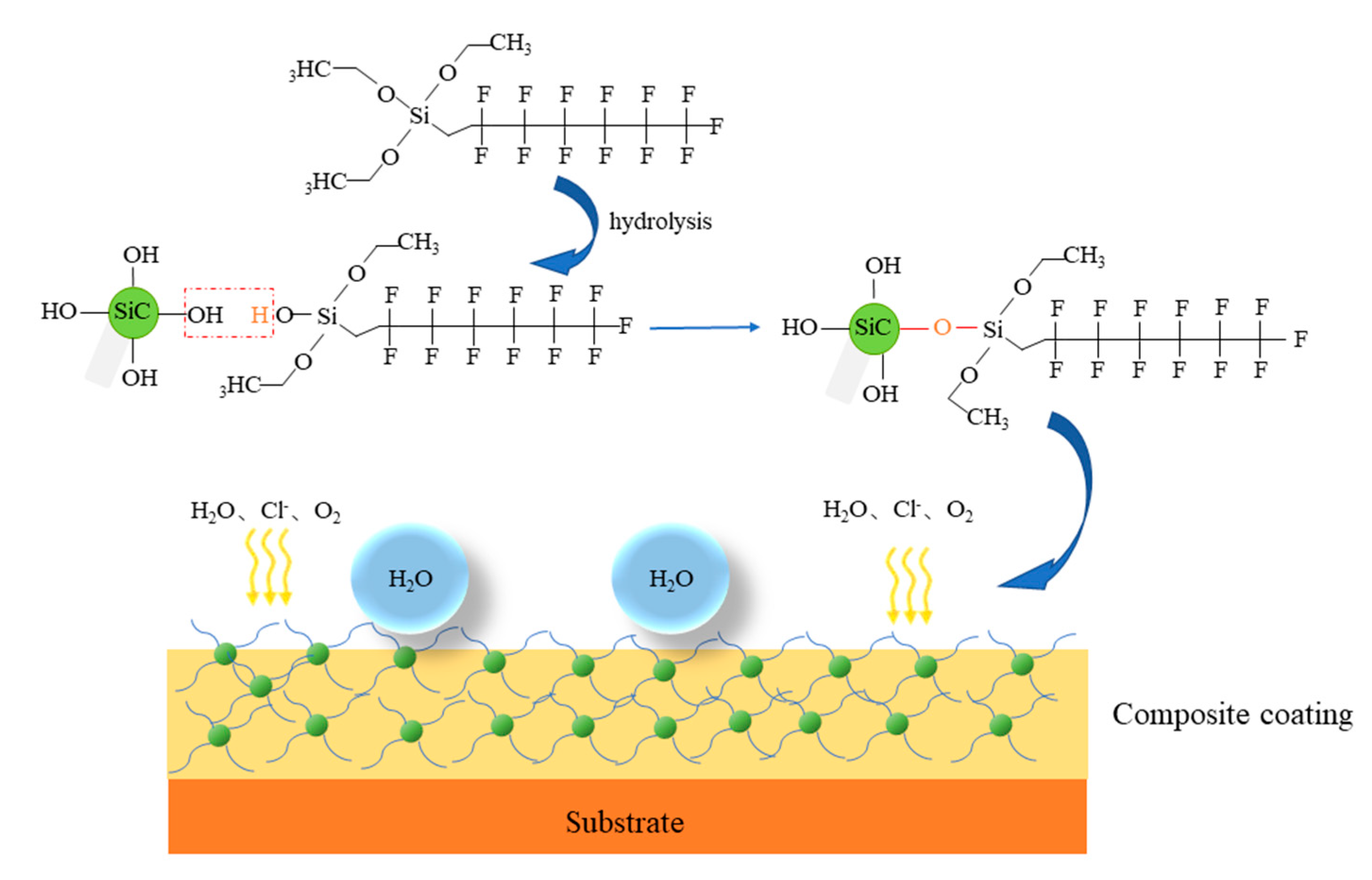
3.1. The Reaction Conditions for the Modification of SiC Powder by FAS

The contact angle characterization has been often used as a relatively simple method for assessing the properties of surfaces. The water contact angle (θ < 90° and θ > 90°) can indicate whether the surface has ‘hydrophilicity’ or ‘hydrophobicity’, respectively [34]. In order to find out the best reaction conditions for the modification SiC by grated FAS, the reaction conditions such as the amount of FAS, reaction temperature and reaction time were studied.
Figure 1 shows the contact angle of SiC as a function of FAS amount and reaction temperature. The SiC particles before modification can be considered as hydrophilic due to a water contact angle of 31.9° (Figure 1a). It is generally accepted that the SiC powder surface has an oxide film and the major functional group on the surface is probably the silanol group (Si–OH), which causes the hydrophilicity of SiC [24].
After being modified by FAS, the hydrophobicity of SiC was effectively improved. It can be clearly observed that as the number of hydrophobic modifiers increases, the contact of F–SiC does not increase significantly at first, but increases rapidly as the addition amount of silane coupling rises over 0.2 g, and finally gradually tends to be stable. When the addition amount of FAS reaches 0.8 g, the static water contact angle of F–SiC exceeds 150° (roll-off angle is 4.2°) and becomes superhydrophobic SiC. The results show that the addition amount of the hydrophobic modifier FAS plays an important role in the modification of SiC powder. The reason may be that more and more silane alcohol groups will react with –OH on the SiC surface through alcohol hydroxyl groups when the silane is hydrolyzed continuously, so the contact angle is increased with the degree of grafting [35,36].
The influence of different reaction temperature on SiC modification is investigated, as shown in Figure 1b. It can be seen that the contact angle first increases and then decreases as the reaction temperature increases. The maximum contact angle is obtained at 70 °C. This is because the hydrolysis process of silane was accelerated by the increasing reaction temperature which could promote the condensation reaction of –OH on the SiC surface with hydrophobic silane. The basic reaction scheme is that the silane is firstly hydrolyzed to produce an alcoholic hydroxyl group, and then the H of the hydroxyl group reacts with the –OH on the SiC surface to form a chemical bond. However, when the temperature is higher than 70 °C, the Brownian movement among SiC particles becomes so fierce to aggravate them, which reduces the extent of grafting. Moreover, as the temperature increases, the silane coupling agent will have a strong tendency to self-polymerize, then the graft coupling agent on the SiC surface may be depolymerized. Therefore, the contact angle decreases with the reduced degree of grafting [30,37,38].
In order to further analyze the grating degree of FAS addition on SiC surface, thermogravimetric analysis (TGA) tests were carried out on F–SiC with different addition amounts of FAS (0–0.8 g). As shown in Figure 2, the weight loss of the sample is divided into two stages. The first stage occurred in the range of 30–420 °C, which was related to the desorption of physically adsorbed water and unreacted silane in the nanoparticles. The second stage occurs in the temperature range of 420–660 °C, which was mainly due to the degradation of long-chain organics grafted to the surface of SiC. Therefore, the weight loss ratio in stage 2 is the ratio of silane in the chemical reaction. When the content of FAS was 0.1 g, the weight loss of the second stage was almost very low, which indicates that there were few grafted organics. However, when the content of FAS increased to 0.8 g, the weight loss of the second stage increased sharply, indicating that the number of grafted organics was also increased. The quantity loss at each stage is shown in Table 1.

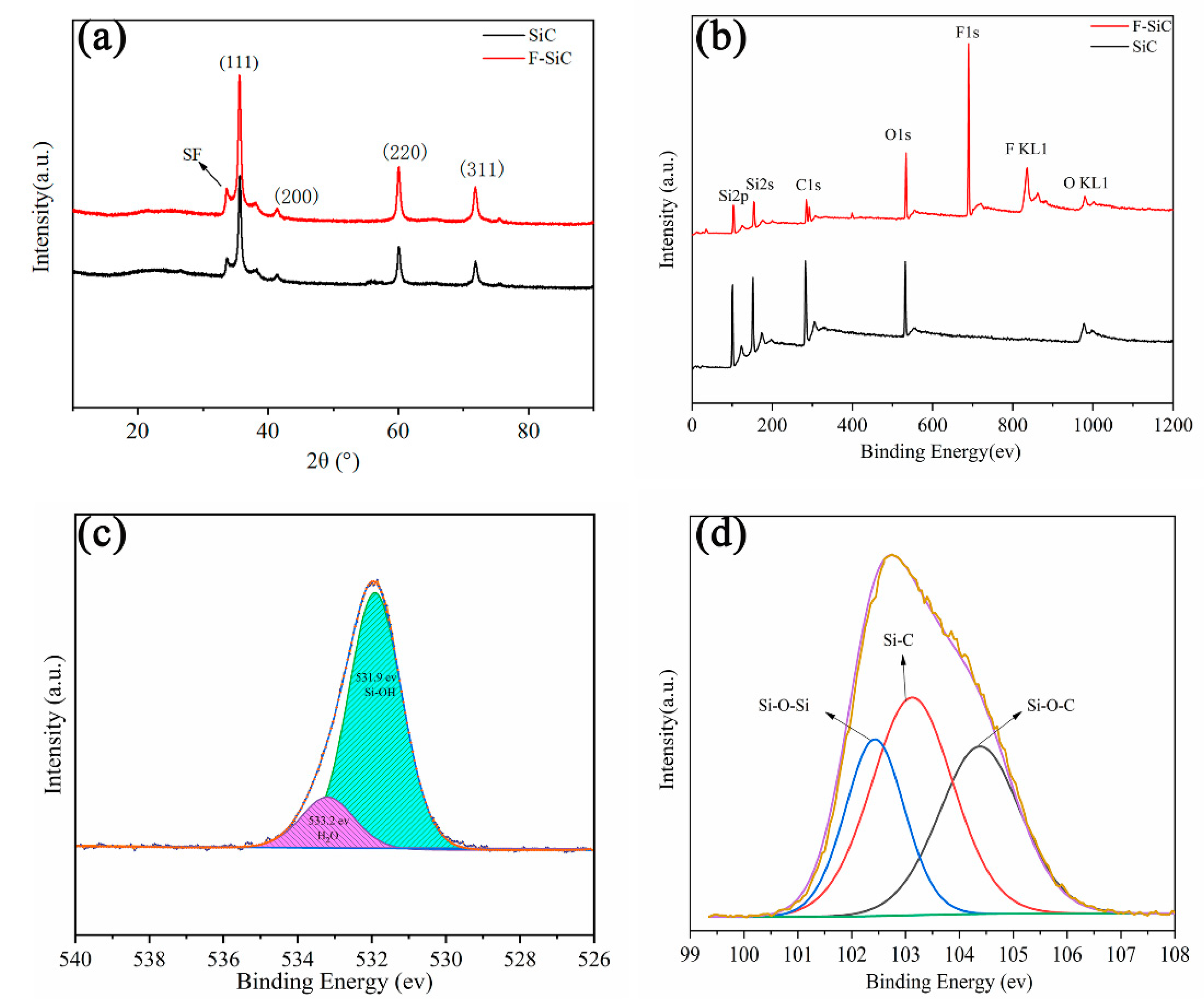
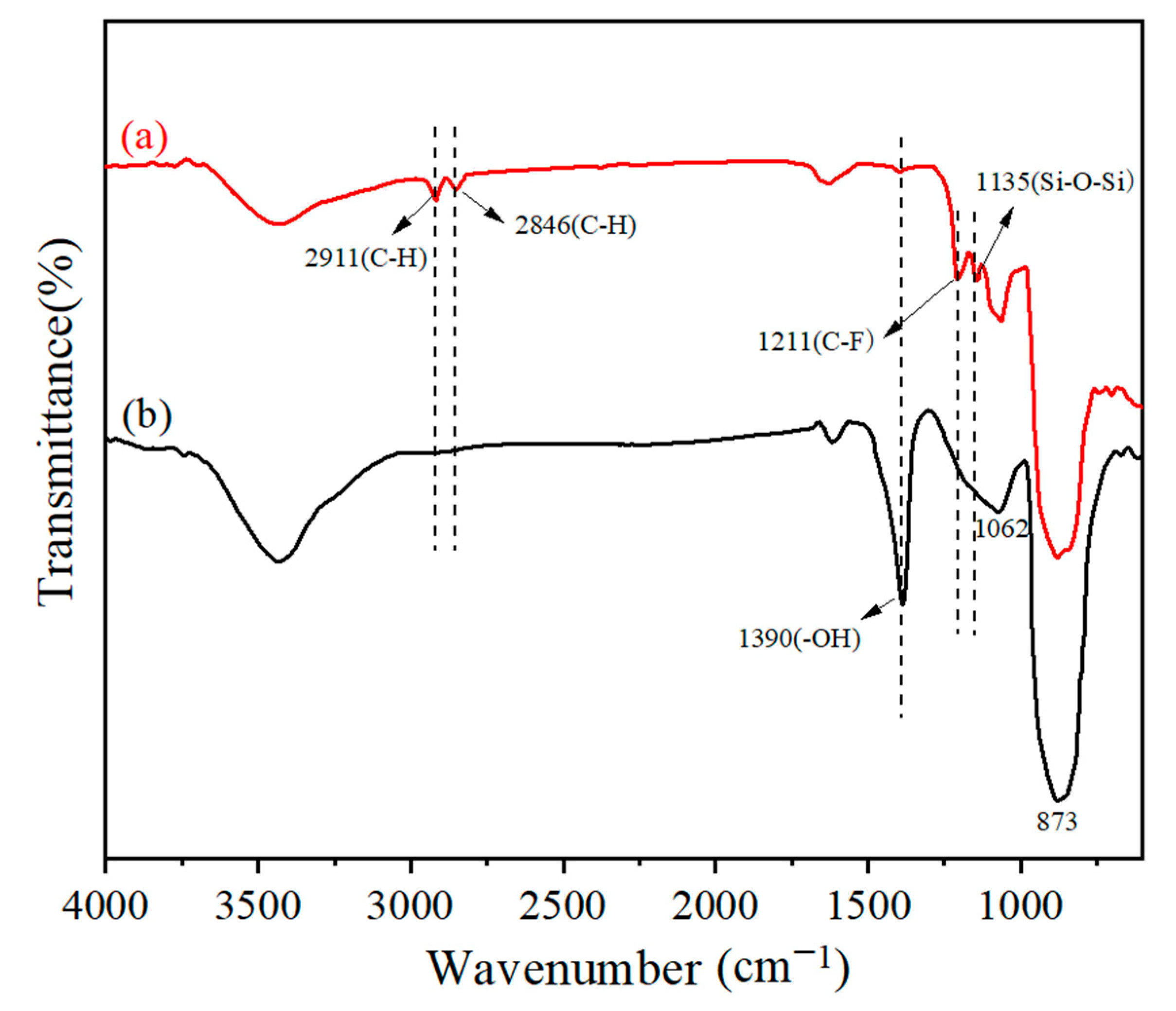
3.2. The Structural Characterization of F–SiC Powder

In this study, XRD was used to identify the structure of SiC before and after modification. Figure 3a is the XRD diagram of SiC before and after modification. It can be seen from the figure that the position and intensity of diffraction peaks before and after modification have not changed, and the positions of diffraction peaks are consistent with the previous literatures [39,40]. It should be noted that the SF peak is caused by stacking faults of SiC [41,42]. In addition, XPS is used to characterize the change of chemical valence before and after modification. Figure 3b shows the XPS spectra of SiC and F–SiC. It can be seen from the figure that SiC mainly contains Si, C and O elements without modification, while a strong F element peak was added after modification, which came from hydrophobic modifier FAS. Figure 3c shows the high-resolution spectra of O 1s in SiC. It is remarkable that the spectra of O 1s are mainly divided into Si–OH and H–OH, respectively. The Si–OH comes from the –OH on the surface of SiC, which is consistent with the reports in the literature [24]. H–OH is considered as the introduction of adsorbed water on the SiC surface. Figure 3d shows the high-resolution spectra of Si 2s in F–SiC. The spectra of Si 2s are mainly fitting to three peaks, namely Si–O–Si, Si–C and Si–O–C. Among them, the Si–C peak is attributed to the SiC particles. The alcoholic hydroxyl groups of the hydrolyzed FAS and the hydroxyl groups on the surface of the SiC undergo a dehydration reaction to form Si–O–Si. This result can be mutually verified with Figure 4, indicating the grafting process success. Finally, Si–O–C comes from the unhydrolyzed groups in FAS. The above discussion shows that FAS was successfully grafted on the surface of SiC.
To verify the above analysis, the FTIR spectra are used to identify functional groups and show vibrational modes of the bonds on the SiC surface. Figure 5 shows the FTIR spectra before and after modification with FAS. The peaks at 1062 and 873 cm−1 are characteristic peaks of SiC. The peaks at 2846 and 2911 cm−1 are mainly the stretching vibrations of C–H [43], which are primarily related to the methylene introduced by FAS modification. In addition, the absorption peak at 1135 cm−1 belongs to the stretching vibration of Si–O–Si [35], and the tensile vibration peak of C–F appears at 1211 cm−1 [44], which indicates that FAS has been successfully chemically bonded to SiC powder in the form of covalent bonding. After modification, the –OH flexural vibration peak at 1390 cm−1 is significantly weakened, indicating that –OH was consumed by FAS. Combining with the previous expression, it can be seen that the reaction between FAS and SiC is chemical bonding rather than simple physical adsorption.

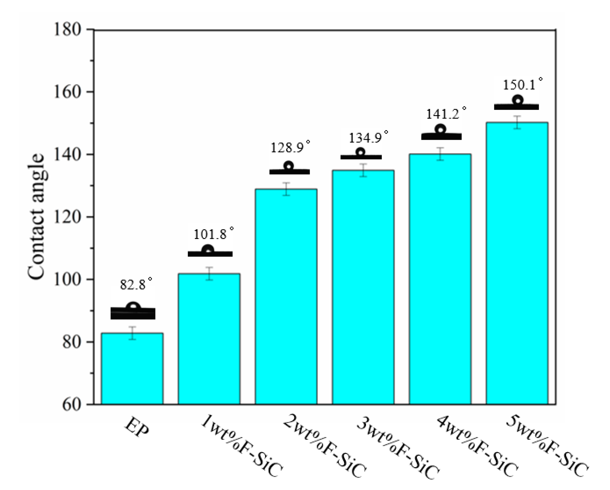
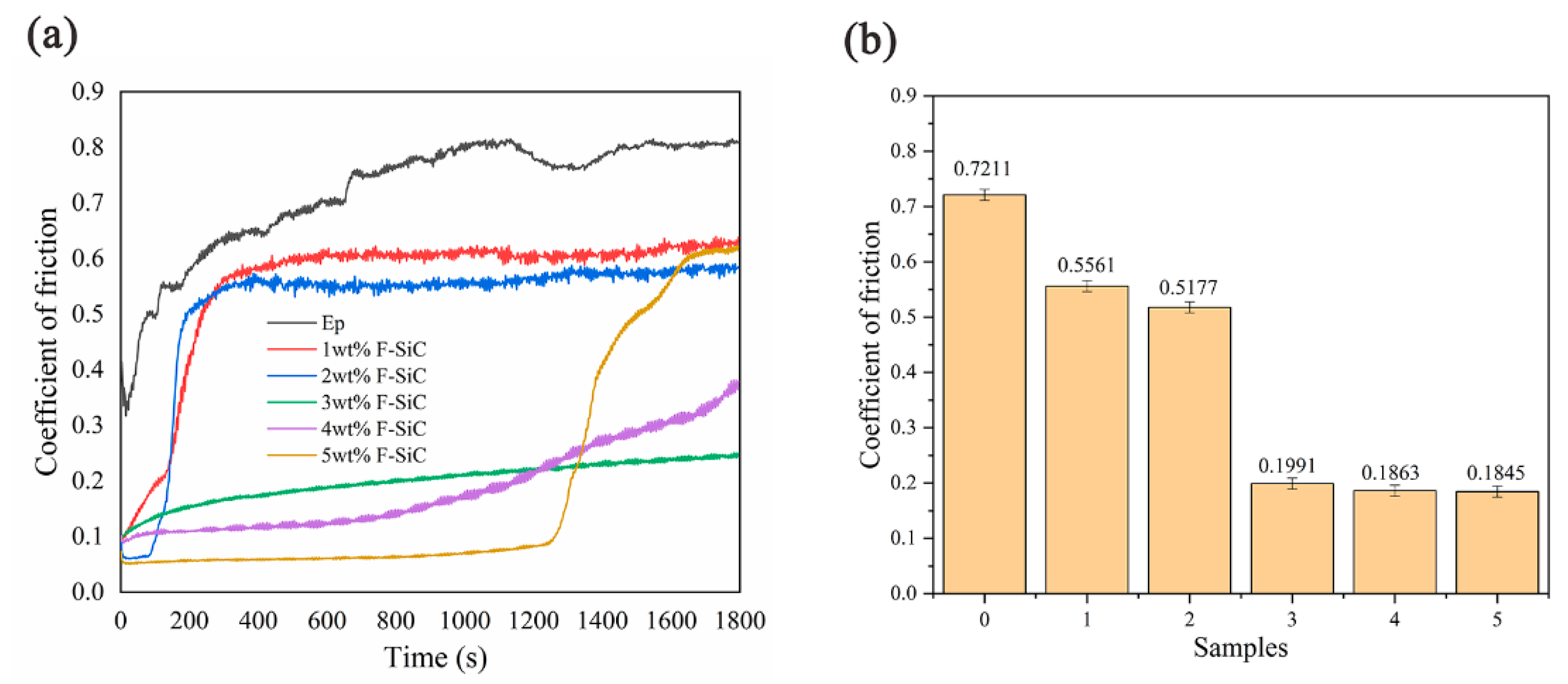
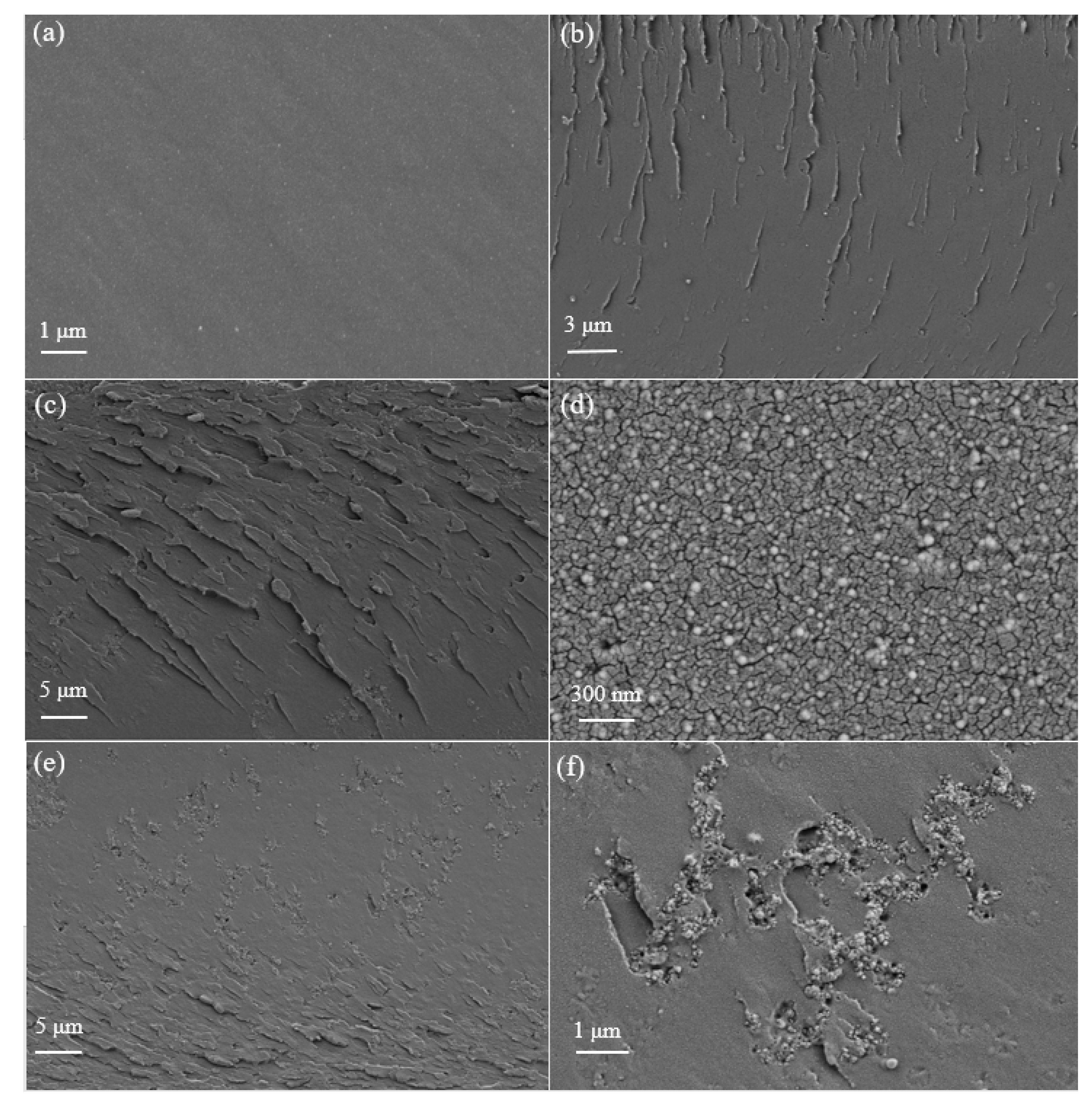
3.3. The Structural Characterization of the Coating System

The hydrophobicity of the composite coating with different content of F–SiC is characterized by the contact angle, and the test results are shown in Figure 6. It can be seen from Figure 6 that the contact angle of the coating is less than 90° without the addition of F–SiC. The contact angle of the coating increases significantly with the addition of F–SiC. A composite coating with superhydrophobic property was obtained as the added F–SiC reached 5 wt %, where a static water contact angle of 150.1° was achieved (roll-off angle is 5.5°).
Moreover, the wear resistance of EP composite coating will be greatly improved due to the super wear-resistance of SiC. The friction coefficients of the composite coating with different tested F–SiC samples are shown in Figure 7. It is well known that the epoxy resin is commonly hard and brittle, and has a low fracture energy and poor wear resistance. During the friction process, EP will undergo an oxidation reaction. The surface macromolecular chains deform under the action of shear stress, and the chemical and hydrogen bonds within and between the molecular chains are broken [45]. Therefore, the friction coefficient of EP is relatively high, and the friction process is very unstable. The friction coefficient of the composite coating is significantly reduced after adding F–SiC nanoparticles to EP, which can be attributed to two reasons [43]. On the one hand, nanofillers use their own hardness to limit the movement of the surrounding epoxy macromolecules and polymer chains and play a supporting role under load. On the other hand, the properties and geometry of the superhydrophobic surface and surface–liquid interaction will affect the friction of the coating surface [46]. The superhydrophobic wetting state converts the surface into quasi-frictionless due to the very small solid–liquid contact area, resulting from the hydrophobic surface chemistry and laboratory micro-nanoroughening. It is worth noting that although the friction coefficient of the coating decreases with the increase in F–SiC content, when the amount of addition exceeds 3 wt %, instability appears in the middle and later stages of coating friction (Figure 7a). The average friction coefficient of each sample is shown in Figure 7b. As the content of F–SiC increases, the average friction coefficient decreases sharply. When the content reaches 3 wt %, the friction coefficient is very low, and the subsequent increase has little effect on the reduction in the friction coefficient.
The microstructures and morphologies of EP, 1 wt % F–SiC/EP, 3 wt % F–SiC/EP, 5 wt % F–SiC/EP were studied by SEM as shown in Figure 8. It can be seen from Figure 8a that the fracture surface of EP exhibits very smooth characteristics. The surface is relatively smooth without obvious defects, indicating brittle fracture and low fracture toughness [47,48], and due to the volatilization of the thinner, there are many steam holes in the coating.
When nano fillers with different contents are dispersed in epoxy resin, the fracture surface morphology of epoxy resin changes greatly. The SEM image of the 1 wt % F–SiC/EP composite coating (Figure 8b) shows more obvious cracks than the pure EP coating (Figure 8a), and the breaking cracks caused by different addition contents are also different. When a small amount of F–SiC is added, the cracks are less and show a streak shape; when the amount of addition is large, the cracks increase rapidly and appear lamellar, which is mainly due to the existence of F–SiC interfering with the directional fracture mode and inhibiting the crack growth [14]. In Figure 8d, it can be seen that the modified nano-SiC particles are more evenly distributed in the resin without agglomeration and have good dispersibility. However, When the F–SiC content increases to 5 wt %, the volume ratio of SiC powder to EP is very large, resulting in SiC content which is too high. These can be seen from the SEM images (Figure 8e,f).

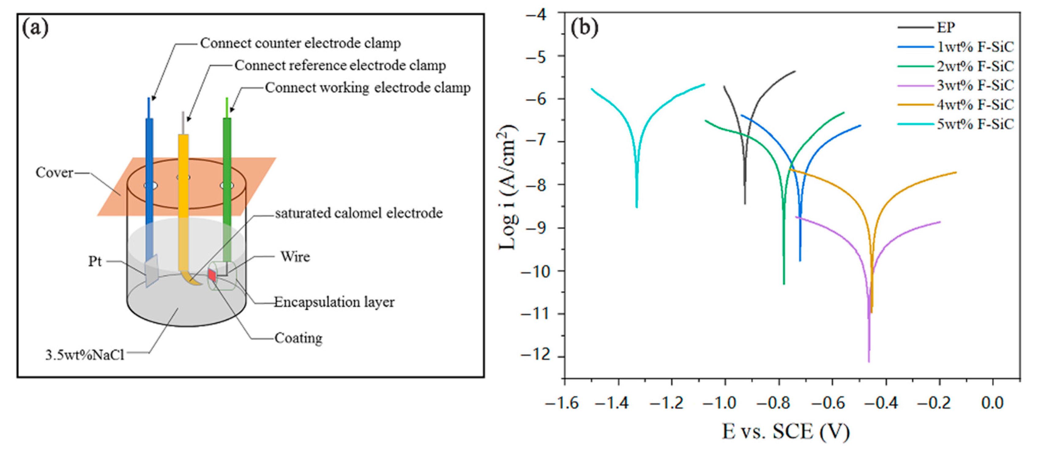
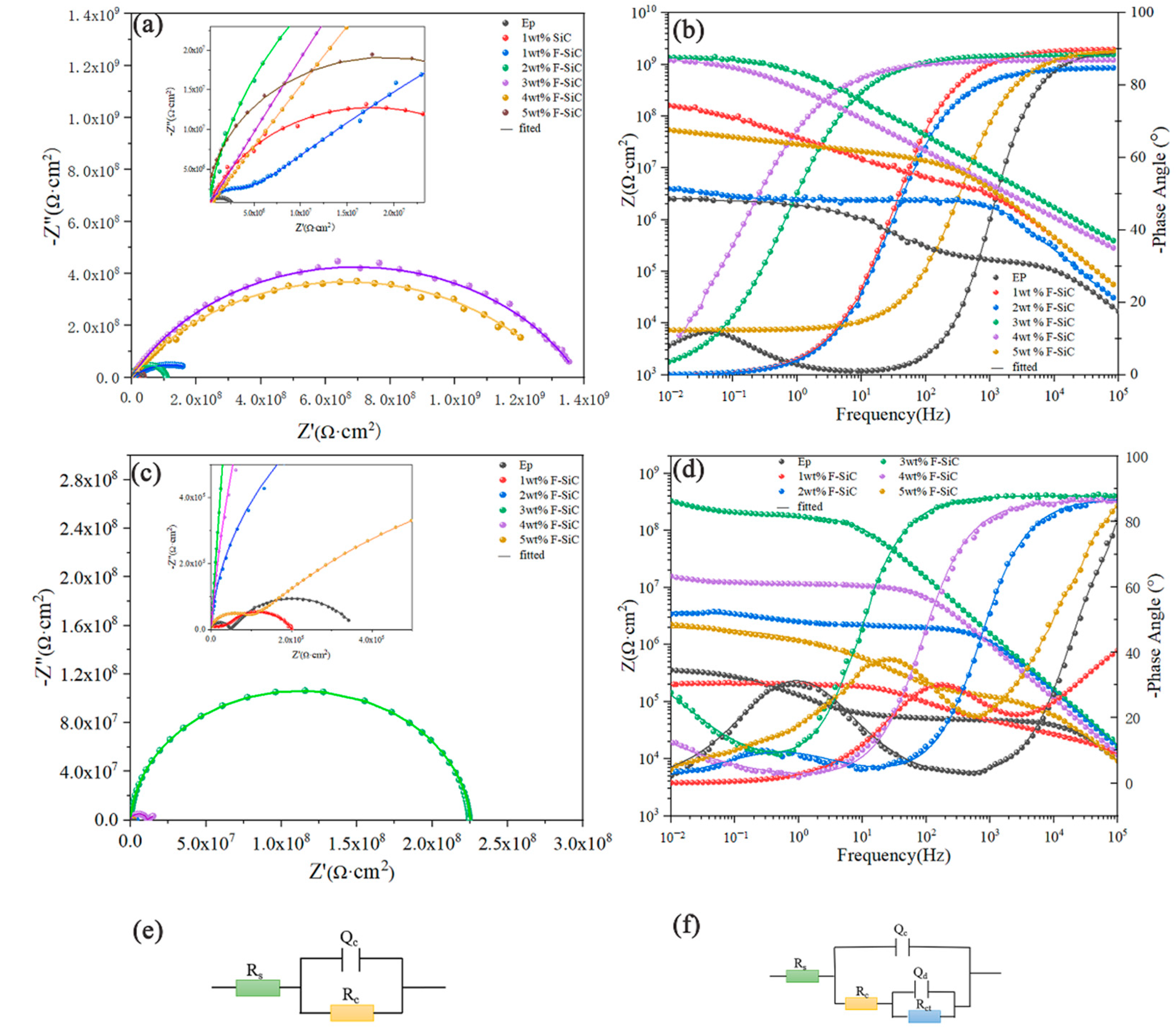
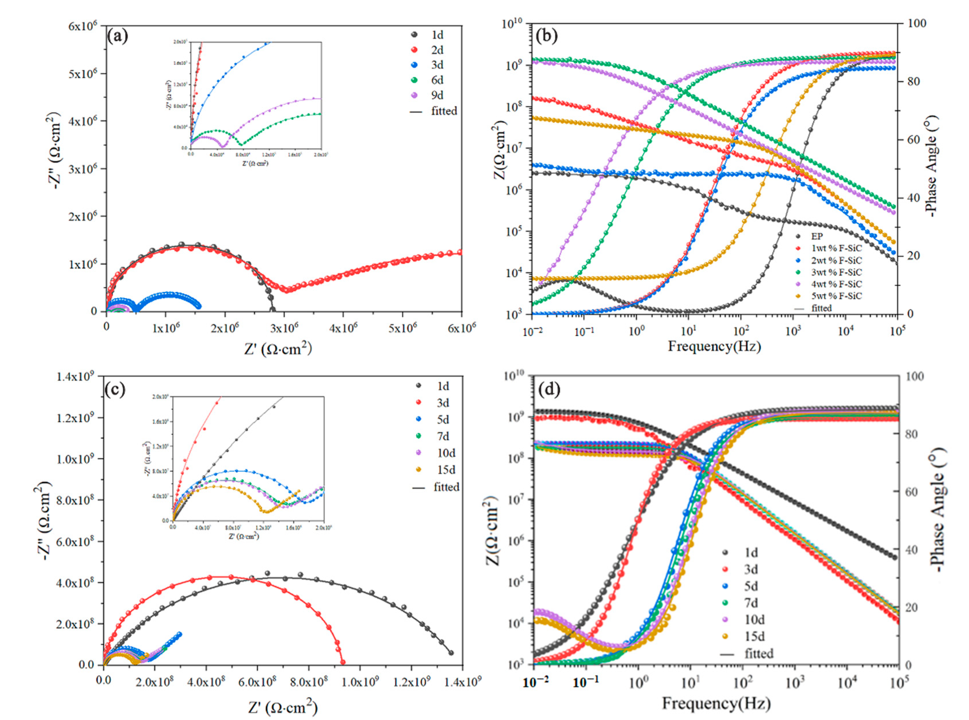
3.4. Corrosion Inhibitive Performance of Composite Coatings

The electrochemical test is used to estimate the corrosion inhibitive performance of composite coatings as shown in Figure 9a. The corrosion inhibition effect of nanoparticles is analyzed by a potential polarization experiment. The polarization curve of the coating after being immersed in 3.5 wt % NaCl solution for 24 h is shown in Figure 9b. The electrochemical parameters include corrosion current density (icorr), corrosion potential (Ecorr), anode (βa) and cathode (βc). A Tafel slope is shown in Table 2. The corrosion current density (icorr) can be obtained from the Tafel diagram by extrapolating the straight-line part (Ecorr) of the corrosion potential curve [49].
It can be seen that the pure EP coating has relatively negative corrosion potential and high corrosion current, but when adding a certain amount of F–SiC, the corrosion potential of the composite coating moves to the positive potential direction, and the corrosion current decreases. When the content of F–SiC is 3–4 wt %, the corrosion potential of the composite coating reaches the maximum value, and the corrosion current is extremely low. As shown in Table 2, the corrosion current of the composite coating added with F–SiC is 2–3 orders of magnitude lower than that of the pure EP coating, and the corrosion resistance of the coating is greatly improved.
Electrochemical impedance spectroscopy (EIS) is further used to evaluate and compare the anti-corrosion performance of composite coatings. Figure 10 shows the Nyquist diagrams and the corresponding Bode diagrams and its Effective circuit model of pure EP and F–SiC/EP coatings with different contents (1–5 wt %) after immersion in 3.5% NaCl aqueous solution for one day and five days. In the equivalent circuit, the parameters of Rs, Rc, Qc, Qdl and Rct correspond to solution resistance, coating resistance, coating capacitance, electric double-layer capacitance, and charge transfer resistance, respectively [50,51]. Generally, the impedance modulus at the lowest frequency (Zf = 0.01 Hz) in the Bode plot can be defined as a parameter for the barrier properties of the coating [52]. After one day of immersion, the Nyquist diagrams all have only one semi-circular arc and only one time constant, and they are all in the early stage of corrosion, as shown in Figure 10a. From Figure 10b, it can be seen that the Zf = 0.01 Hz value of pure epoxy resin is 2.799 × 10⁶ Ω∙cm2, which is much lower than the Zf = 0.01 Hz value (1.386 × 10⁹ Ω∙cm2) added with 3 wt % F–SiC/EP composite coating.
After five days of immersion, the Zf = 0.01 Hz value of the coating has a certain degree of decrease. The Zf = 0.01 Hz value of the pure EP coating drops to 3.551 × 10⁵ Ω∙cm2, and a second arc appears in the Nyquist diagram (Figure 10c), indicating that coating enters the middle stage of corrosion, while the 3 wt % F–SiC/EP coating still has the highest Zf = 0.01 Hz value (3.106 × 10⁵ Ω∙cm2), and its Nyquist diagram shows that the coating is still in the early stage of corrosion.
In order to more intuitively reflect the difference between the pure EP coating and the 3 wt % F–SiC/EP coating, EIS measurements with different immersion times are performed, as shown in Figure 11. The Nyquist diagram of EP coating at two days (Figure 11a) shows the second arc, which indicates that the coating enters the middle corrosion stage the next day, while the 3 wt % F–SiC/EP coating (Figure 11c) enters the intermediate corrosion stage on the 10th day. Moreover, it can be seen from the Bode diagram that the Zf = 0.01 Hz of pure EP coating (Figure 11b) decreases rapidly, while the Zf = 0.01 Hz of 3 wt % F–SiC/EP coating (Figure 11d) maintains a relatively stable value. Detailed electrochemical corrosion data are given in Table 3.

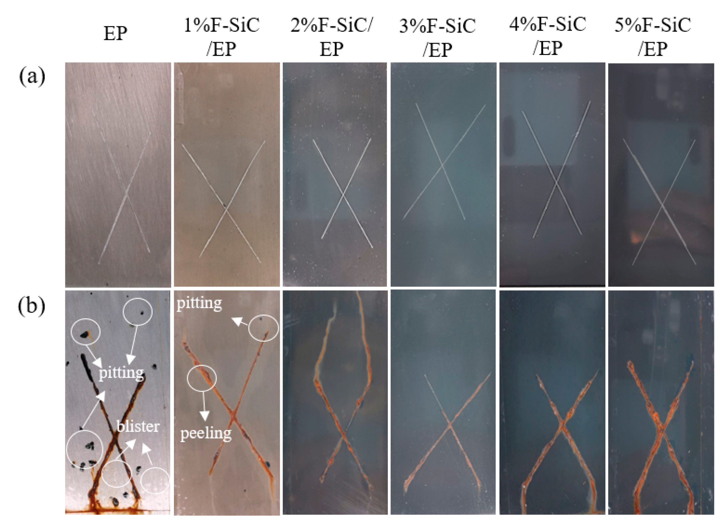
3.5. Salt Spray Corrosion Resistance

A salt spray test was performed to further explore the performance of the composite coating, as shown in Figure 12. Before the experiment, scratches should be made on the surface of the coating to facilitate observation of corrosion. Figure 12b shows different coating samples (EP, 1–5 wt % F–SiC/EP) after 240 h of salt spray test. It can be seen that after 240 h of salt spray test, the pure EP coating and the coating with low F–SiC content have many blisters on both sides of the scratch, and the corrosion depth is considerably high. Within the range of 2 mm, pitting corrosion will occur in the area not scratched. The pitting corrosion and blistering of the 2–3 wt % F–SiC/EP composite coating are improved, but when the F–SiC content is further increased, the corrosion range near the scratch becomes larger and the rust phenomenon becomes serious. The results show that the shielding performance of the coating can be enhanced by adding an appropriate amount of F–SiC composite. In addition, the F–SiC/EP composite coating with about 3 wt % has the best anti-corrosion performance, which is consistent with the results of EIS.
In this work, good results have been obtained, and we have also compared the anti-corrosion performance of similar materials in the literature. The comparison of the results is shown in Table 4.

4. Conclusions

First of all, the hydrophilic surface of SiC was modified into hydrophobic material by chemical grafting, and the contact angle of F–SiC was greatly improved. Next, filling F–SiC into EP can significantly improve the hydrophobicity, wear resistance and corrosion resistance of the coating. As the amount of F–SiC added increases, the coating gradually changes from a hydrophilic coating to a superhydrophobic coating. When 3 wt % F–SiC was added, the coating had the best tribological properties. Finally, the coatings with different proportions were tested, and it was found that the coating containing 3 wt % F–SiC had the best improvement in the overall performance.

Author Contributions

Conceptualization, X.O.; investigation, B.L.; methodology, Z.Z.; writing—original draft, Z.Z. and Z.Z.; writing—review and editing, F.Q., N.Z., and B.Z. All authors have read and agreed to the published version of the manuscript.

Funding

This research was funded by National Natural Science Foundation of China (51701172); Educational Commission of Hunan Province of China (20B579); Hunan Provincial Natural Science Foundation of China (2020JJ4086, 2018JJ4053), Scientific Research Fund of Hunan Provincial Education Department (19B570), the China Postdoctoral Science Foundation (2017M622595, 2018M632977), Major Program of Hunan Province (2018RS3091).

Conflicts of Interest

The authors declare no conflict of interest.

References

  1. Chauhan, D.S.; Quraishi, M.A.; Ansari, K.R.; Saleh, T.A. Graphene and graphene oxide as new class of materials for corrosion control and protection: Present status and future scenario. Prog. Org. Coat. 2020, 147, 105741. [Google Scholar] [CrossRef]
  2. Sun, P.; Wang, Z.; Lu, Y.; Shen, S.; Yang, R.; Xue, A.; Parker, T.; Wang, J.; Wang, Q. Analysis of the corrosion failure of a semiconductor polycrystalline distillation column. Process Saf. Environ. Prot. 2020, 135, 244–256. [Google Scholar] [CrossRef]
  3. Bradl, H.B. Adsorption of heavy metal ions on soils and soils constituents. J. Colloid Interface Sci. 2004, 277, 1–18. [Google Scholar] [CrossRef] [PubMed]
  4. Chajduk, E.; Bojanowska-Czajka, A. Corrosion mitigation in coolant systems in nuclear power plants. Prog. Nucl. Energy 2016, 88, 1–9. [Google Scholar] [CrossRef]
  5. Tang, Z. A review of corrosion inhibitors for rust preventative fluids. Curr. Opin. Solid State Mater. Sci. 2019, 23, 100759. [Google Scholar] [CrossRef]
  6. Grundmeier, G.; Schmidt, W.; Stratmann, M. Corrosion protection by organic coatings: Electrochemical mechanism and novel methods of investigation. Electrochim. Acta 2000, 45, 2515–2533. [Google Scholar] [CrossRef]
  7. Li, M.; Hu, P.; Zhang, Y.; Chang, Y. Enhancing performance of the CuCrZrTiV alloys through increasing recrystallization resistance and two-step thermomechanical treatments. J. Nucl. Mater. 2021, 543, 152482. [Google Scholar] [CrossRef]
  8. Zhang, J.J.; Liu, J.C.; Liao, H.M.; Zeng, M.; Ma, S. A review on relationship between morphology of boride of Fe-B alloys and the wear/corrosion resistant properties and mechanisms. Mater. Today Proc. 2020, 8, 6308–6320. [Google Scholar] [CrossRef]
  9. Fallah, P.; Rajagopalan, S.; McDonald, A.; Yue, S. Development of hybrid metallic coatings on carbon fiber-reinforced polymers (CFRPs) by cold spray deposition of copper-assisted copper electroplating process. Surf. Coat. Technol. 2020, 400, 126231. [Google Scholar] [CrossRef]
  10. Lim, J.; Lee, C. The rf-power dependences of the deposition rate, the hardness and the corrosion-resistance of the chromium nitride film deposited by using a dual ion beam sputtering system. Mater. Chem. Phys. 2006, 95, 164–168. [Google Scholar] [CrossRef]
  11. Olajire, A.A. Recent advances on organic coating system technologies for corrosion protection of offshore metallic structures. J. Mol. Liq. 2018, 269, 572–606. [Google Scholar] [CrossRef]
  12. Han, Y.H.; Taylor, A.; Knowles, K.M. Scratch resistance and adherence of novel organic-inorganic hybrid coatings on metallic and non-metallic substrates. Surf. Coat. Technol. 2009, 203, 2871–2877. [Google Scholar] [CrossRef]
  13. Deering, J.; Clifford, A.; D’Elia, A.; Zhitomirsky, I.; Grandfield, K. Composite dip coating improves biocompatibility of porous metallic scaffolds. Mater. Lett. 2020, 274, 128057. [Google Scholar] [CrossRef]
  14. Jin, F.L.; Li, X.; Park, S.J. Synthesis and application of epoxy resins: A review. J. Ind. Eng. Chem. 2015, 29, 1–11. [Google Scholar] [CrossRef]
  15. Xia, Y.; He, Y.; Chen, C.; Wu, Y.; Chen, J. MoS2 nanosheets modified SiO2 to enhance the anticorrosive and mechanical performance of epoxy coating. Prog. Org. Coat. 2019, 132, 316–327. [Google Scholar] [CrossRef]
  16. Li, B.; Mao, B.; Wang, X.; He, T. Fabrication and frictional wear property of bamboo-like SiC nanowires reinforced SiC coating. Surf. Coat. Technol. 2020, 389, 125647. [Google Scholar] [CrossRef]
  17. Sekhavat Pour, Z.; Ghaemy, M.; Bordbar, S.; Karimi-Maleh, H. Effects of surface treatment of TiO2 nanoparticles on the adhesion and anticorrosion properties of the epoxy coating on mild steel using electrochemical technique. Prog. Org. Coat. 2018, 119, 99–108. [Google Scholar] [CrossRef]
  18. Oliveira, J.D.; Rocha, R.C.; Galdino, A.G.D.S. Effect of Al2O3 particles on the adhesion, wear, and corrosion performance of epoxy coatings for protection of umbilical cables accessories for subsea oil and gas production systems. J. Mater. Res. Technol. 2019, 8, 1729–1736. [Google Scholar] [CrossRef]
  19. Hu, C.; Li, Y.; Kong, Y.; Ding, Y. Preparation of poly(o-toluidine)/nano ZnO/epoxy composite coating and evaluation of its corrosion resistance properties. Synth. Met. 2016, 214, 62–70. [Google Scholar] [CrossRef]
  20. Wu, R.; Zhou, K.; Yue, C.Y.; Wei, J.; Pan, Y. Recent progress in synthesis, properties and potential applications of SiC nanomaterials. Prog. Mater. Sci. 2015, 72, 1–60. [Google Scholar] [CrossRef]
  21. Fan, J.Y.; Wu, X.L.; Chu, P.K. Low-dimensional SiC nanostructures: Fabrication, luminescence, and electrical properties. Prog. Mater. Sci. 2006, 51, 983–1031. [Google Scholar] [CrossRef]
  22. Yang, Y.; Lai, L.Y.; Ding, G.F.; Chen, T. SiC nanowire-based SU-8 with enhanced mechanical properties for MEMS structural layer design. Nanotechnol. Precis. Eng. 2020, 2, 169–176. [Google Scholar] [CrossRef]
  23. Zhang, W.; Yamashita, S.; Kita, H. Progress in tribological research of SiC ceramics in unlubricated sliding-A review. Mater. Des. 2020, 190, 108528. [Google Scholar] [CrossRef]
  24. Rahaman, M.N.; Boiteux, Y.; Dejonghe, L.C. Surface characterization of silicon nitride and silicon carbide powders. Am. Ceram. Soc. Bull. 1985, 65, 171–176. [Google Scholar]
  25. Naeimirad, M.; Zadhoush, A.; Neisiany, R.E. Fabrication and characterization of silicon carbide/epoxy nanocomposite using silicon carbide nanowhisker and nanoparticle reinforcements. J. Compos. Mater. 2016, 50, 435–446. [Google Scholar] [CrossRef]
  26. Kychkin, A.A.; Anan’Eva, E.S.; Tankova, K.I.; Kychkin, A.K.; Tuisov, A.G. Influence of ultrafine silicon carbide powders on the properties of epoxy resin. Struct. Integr. 2019, 20, 185–189. [Google Scholar] [CrossRef]
  27. Nigrawal, A.; Buddi, T.; Rana, R.S.; Purohit, R. Development of epoxy/nano SiC composites and their mechanical studies. Mater. Today Proc. 2019, 18, 4384–4391. [Google Scholar] [CrossRef]
  28. Iijima, M.; Kamiya, H. Surface modification of silicon carbide nanoparticles by azo radical initiators. J. Phys. Chem. C 2008, 112, 397–398. [Google Scholar] [CrossRef]
  29. Huang, L.Y.; Lu, C.X.; Wang, F.; Dong, X.Z. Piezoelectric property of PVDF/graphene composite films using 1H,1H,2H,2H-Perfluorooctyltriethoxysilane as a modifying agent. J. Alloys Compd. 2016, 688, 885–892. [Google Scholar] [CrossRef]
  30. Shang, X.; Zhu, Y.; Li, Z. Surface modification of silicon carbide with silane coupling agent and hexadecyl iodiele. Appl. Surf. Sci. 2017, 394, 169–177. [Google Scholar] [CrossRef]
  31. Esmeryan, K.D.; Mchale, G.; Trabi, C.L.; Geraldi, N.R.; Newton, M.I. Manipulated wettability of a superhydrophobic quartz crystal microbalance through electrowetting. J. Phys. D Appl. Phys. 2013, 46, 345307. [Google Scholar] [CrossRef]
  32. Liu, H.D.; Zhang, H.; Pang, J.; Ning, Y.J.; Jia, F.; Yuan, W.F.; Gu, B.; Zhang, Q.P. Superhydrophobic property of epoxy resin coating modified with octadecylamine and SiO2 nanoparticles. Mater. Lett. 2019, 247, 204–207. [Google Scholar] [CrossRef]
  33. Usman, B.J.; Scenini, F.; Curioni, M. The effect of exposure conditions on performance evaluation of post-treated anodic oxides on an aerospace aluminium alloy: Comparison between salt spray and immersion testing. Surf. Coat. Technol. 2020, 399, 126157. [Google Scholar] [CrossRef]
  34. Kulkarni, S.A.; Ogale, S.B.; Vijayamohanan, K.P. Tuning the hydrophobic properties of silica particles by surface silanization using mixed self-assembled monolayers. J. Colloid Interface Sci. 2008, 318, 372–379. [Google Scholar] [CrossRef]
  35. Palimi, M.J.; Rostami, M.; Mahdavian, M.; Ramezanzadeh, B. Surface modification of Cr2O3 nanoparticles with 3-amino propyl trimethoxy silane (APTMS). Part 1: Studying the mechanical properties of polyurethane/Cr2O3 nanocomposites. Prog. Org. Coat. 2014, 77, 1663–1673. [Google Scholar] [CrossRef]
  36. Palimi, M.J.; Rostami, M.; Mahdavian, M.; Ramezanzadeh, B. Surface modification of Fe2O3 nanoparticles with 3-aminopropyltrimethoxysilane (APTMS): An attempt to investigate surface treatment on surface chemistry and mechanical properties of polyurethane/Fe2O3 nanocomposites. Appl. Surf. Sci. 2014, 320, 60–72. [Google Scholar] [CrossRef]
  37. Sabzi, M.; Mirabedini, S.M.; Zohuriaan-Mehr, J.; Atai, M. Surface modification of TiO2 nano-particles with silane coupling agent and investigation of its effect on the properties of polyurethane composite coating. Prog. Org. Coat. 2009, 65, 222–228. [Google Scholar] [CrossRef]
  38. Lin, J.; Siddiqui, J.A.; Ottenbrite, R.M. Surface modification of inorganic oxide particles with Silane coupling agent and organic dyes. Polym. Adv. Technol. 2001, 12, 285–292. [Google Scholar] [CrossRef]
  39. Nechanicky, M.A.; Chew, K.W.; Sellinger, A.; Laine, R.M. α-Silicon carbide/β-silicon carbide particulate composites via polymer infiltration and pyrolysis (PIP) processing using polymethylsilane. J. Am. Ceram. Soc. 2000, 20, 441–451. [Google Scholar] [CrossRef]
  40. Chew, K.W.; Sellinger, A.; Laine, R.M. Processing of aluminum, nitride/silicon carbide composites via polymer infiltration and pyrolysis of polymethylsilane, a precursor to stoichiometric SiC. J. Am. Ceram. Soc. 1999, 82, 857–866. [Google Scholar] [CrossRef] [Green Version]
  41. Iwata, H.P.; Lindefelt, U.; Öberg, S.; Briddon, P.R. Stacking faults in silicon carbide. Physica B 2003, 340, 165–170. [Google Scholar] [CrossRef]
  42. Choi, H.-J.; Lee, J.-G. Stacking faults in silicon carbide whiskers. Ceram. Int. 2000, 26, 7–12. [Google Scholar] [CrossRef]
  43. Yuan, H.; Qi, F.; Zhao, N.; Wan, P.; Zhang, B.; Xiong, H.; Liao, B.; Ouyang, X. Graphene oxide decorated with titanium nanoparticles to reinforce the anti-corrosion performance of epoxy coating. Coatings 2020, 10, 129. [Google Scholar] [CrossRef] [Green Version]
  44. Georgakilas, V.; Bourlinos, A.B.; Zboril, R.; Trapalis, C. Synthesis, Characterization and aspects of superhydrophobic functionalized carbon nanotubes. Chem. Mater. 2008, 20, 2884–2886. [Google Scholar] [CrossRef]
  45. Shi, G.; Zhang, M.Q.; Rong, M.Z.; Wetzel, B.; Friedrich, K. Friction and wear of low nanometer Si3N4 filled epoxy composites. Wear 2003, 254, 784–796. [Google Scholar] [CrossRef]
  46. Mishchenko, L.; Hatton, B.; Bahadur, V.; Taylor, J.A.; Krupenkin, T.; Aizenberg, J. Design of ice-free nanostructured surfaces based on repulsion of impacting water droplets. ACS Nano 2010, 4, 7699–7707. [Google Scholar] [CrossRef] [PubMed]
  47. Lu, S.; Li, S.; Yu, J.; Yuan, Z.; Qi, B. Epoxy nanocomposites filled with thermotropic liquid crystalline epoxy grafted graphene oxide. RSC Adv. 2013, 3, 8915–8923. [Google Scholar] [CrossRef]
  48. Bortz, D.R.; Heras, E.G.; Martin-Gullon, I. Impressive fatigue life and fracture toughness improvements in graphene oxide/epoxy composites. Macromolecules 2012, 45, 238–245. [Google Scholar] [CrossRef]
  49. Pourhashem, S.; Ghasemy, E.; Rashidi, A.; Vaezi, M.R. Corrosion protection properties of novel epoxy nanocomposite coatings containing silane functionalized graphene quantum dots. J. Alloys Compd. 2018, 731, 1112–1118. [Google Scholar] [CrossRef]
  50. Xia, W.; Xue, H.; Wang, J.; Wang, T.; Song, L.; Guo, H.; Fan, X.; Gong, H.; He, J. Functionlized graphene serving as free radical scavenger and corrosion protection in gamma-irradiated epoxy composites. Carbon 2016, 101, 315–323. [Google Scholar] [CrossRef]
  51. Cano, E.; Lafuente, D.; Bastidas, D.M. Use of EIS for the evaluation of the protective properties of coatings for metallic cultural heritage: A review. J. Solid State Electrochem. 2010, 14, 381–391. [Google Scholar] [CrossRef] [Green Version]
  52. Tian, W.; Meng, F.; Liu, L.; Li, Y.; Wang, F. The failure behaviour of a commercial highly pigmented epoxy coating under marine alternating hydrostatic pressure. Prog. Org. Coat. 2015, 82, 101–112. [Google Scholar] [CrossRef]
  53. Zhi, D.; Wang, H.; Jiang, D.; Parki, I.P.; Zhang, X. Reactive silica nanoparticles turn epoxy coating from hydrophilic to super-robust superhydrophobic. RSC Adv. 2019, 9, 12547–12554. [Google Scholar] [CrossRef] [Green Version]
  54. Xiong, H.; Qi, F.; Zhao, N.; Yuan, H.; Wan, P.Y.; Liao, B.; Ouyang, X.P. Effect of organically modified sepiolite as inorganic nanofiller on the anti-corrosion resistance of epoxy coating. Mater. Lett. 2019, 260, 126941. [Google Scholar] [CrossRef]
  55. Xu, Y.S.H.; Gao, D.; Dong, Q.; Li, M.H.; Liu, A.; Wang, X.C.; Wang, S.F.; Liu, Q. Anticorrosive behavior of epoxy coating modified with hydrophobic nano-silica on phosphatized carbon steel. Prog. Org. Coat. 2021, 151, 106051. [Google Scholar] [CrossRef]
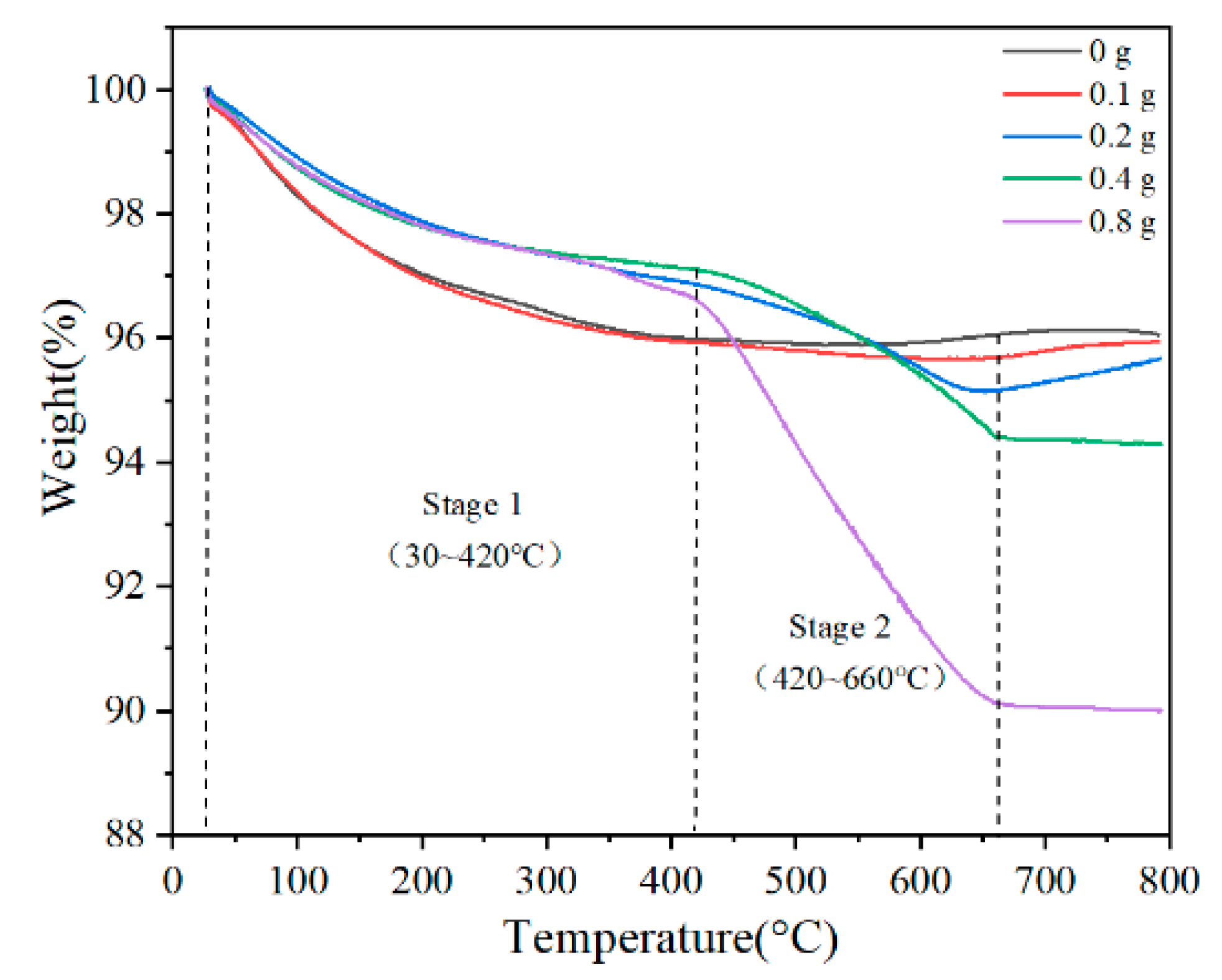
Figure 1. Water contact angle of SiC powder: (a) the effect of silane coupling agent amount, (b) the effect of reaction temperature.
Coatings 10 01244 g001
Figure 2. TGA curves of samples with different contents of FAS.
Coatings 10 01244 g002
Figure 3. X-ray analysis: (a) XRD spectra of SiC before and after modification; (b) XPS spectra of SiC before and after modification; (c) high-resolution XPS spectra of O 1s in SiC; (d) high-resolution XPS spectra of Si in F–SiC.
Coatings 10 01244 g003
Figure 4. Experimental procedures of fabricating F–SiC and composite coating.
Coatings 10 01244 g004
Figure 5. FTIR spectra of the samples: (a) F–SiC, (b) SiC.
Coatings 10 01244 g005
Figure 6. Contact angle of composite coating with different content of F–SiC.
Coatings 10 01244 g006
Figure 7. (a) Friction coefficient versus time, and (b) average friction coefficient of average friction coefficient of different F–SiC addition (0–5 wt %).
Coatings 10 01244 g007
Figure 8. The fracture surface of the nanocomposite coatings: (a) epoxy resin (EP); (b) 1 wt % F–SiC/EP, (c) 3 wt % F–SiC/EP; (d) microscopic enlargement of 3 wt % F–SiC/EP; (e) 5 wt % F–SiC/EP; (f) microscopic enlargement of 5 wt % F–SiC/EP.
Coatings 10 01244 g008
Figure 9. Electrochemical test: (a) electrochemical test model; (b) Tafel diagrams with different coatings.
Coatings 10 01244 g009
Figure 10. The Nyquist diagram (a) and bode diagram (b) of different coatings immersed for 12 h; the Nyquist diagram (c) and bode diagram (d) of different coatings immersed for 48 h; the Fitting circuit in presoaking stage (e) and medium stage (f).
Coatings 10 01244 g010
Figure 11. Nyquist and Bode diagram of (a,b) neat epoxy, (c,d) 3 wt % F–SiC/epoxy.
Coatings 10 01244 g011
Figure 12. Photographs of different coating salt spray tests: (a) before the salt spray test; (b) 240 h after the salt spray test.
Coatings 10 01244 g012
Table 1. The weight loss at different stage and total weight loss of different amount of FAS.
SamplesStage 1 Weight Loss (%) Stage 2 Weight Loss (%)Total Weight Loss at 800 °C (%)
0 g4.02–0.093.93
0.1 g4.020.294.31
0.2 g3.141.714.35
0.4 g2.892.715.71
0.8 g3.396.4910.01
Table 2. The electrochemical corrosion parameters derived by potentiodynamic polarization test.
SamplesEcorr (V vs. SCE)icorr (A/cm2)βa (V/dec)−βc (V/dec)
Blank solution−0.9281.524 × 10−70.0660.071
1 wt % F–SiC/EP−0.7221.754 × 10−80.1180.111
2 wt % F–SiC/EP−0.7862.667 × 10−80.1550.155
3 wt % F–SiC/EP−0.4681.837 × 10−100.3750.417
4 wt % F–SiC/EP−0.4551.751× 10−90.1710.162
5 wt % F–SiC/EP−1.3321.770 × 10−70.1540.139
Table 3. Electrochemical impedance spectroscopy data of neat epoxy and nanocomposite coatings.
SamplesTimeQcRc (Ω∙cm2)QdRct (Ω∙cm2)
Y0−1 cm−2 sn)nY0−1 cm−2 sn)n
EP1 d6.243 × 10−110.9982.799 × 106
2 d1.194 × 10−100.99312.593 × 1062.090 × 10−70.40947.35 × 106
3 d1.757 × 10−100.96554.900 × 1056.899 × 10−70.71691.137 × 106
4 d4.486 × 10−100.9297.531 × 1042.418 × 10−70.60272.493 × 105
5 d3.159 × 10−100.9534.788 × 1042.592 × 10−70.6893.126 × 105
3 wt % F–SiC1 d2.558 × 10−100.9631.386 × 109
3 d2.494 × 10−100.94949.307 × 108
5 d1.378 × 10−100.96542.247 × 108
7 d1.522 × 10−100.95841.821 × 108
10 d1.252 × 10−100.97941.431 × 1084.826 × 10−80.74962.36 0× 108
15 d1.378 × 10−100.97141.202 × 1087.424 × 10−80.78021.386 × 108
Table 4. Comparison of the anti-corrosion performance of similar materials.
SamplesAddition AmountWater Contact AngleAbrasion TestsElectrochemical Impedance SpectroscopySalt Spray Test
F–SiC/EP3 wt %134.9°The friction coefficient was reduced by 73.5%1.386 × 10⁹ Ω∙cm2240 h
SiO2/EP-ODA [32]>35 wt %153.6°The coatings have considerably stable abrasion resistance.
SiO2/EP [53]40 wt %156°The retention ratio was about 78%
OMSEP/EP [54]3 wt %101°about 109 Ω∙cm2240 h
MEC [55]9.09 wt %95.9°5.25 × 10⁵ Ω∙cm2336 h
Publisher’s Note: MDPI stays neutral with regard to jurisdictional claims in published maps and institutional affiliations.

