Article

Significant Improvement of Anticorrosion Properties of Zinc-Containing Coating Using Sodium Polystyrene Sulfonate Noncovalent Modified Graphene Dispersions

1
Electronic Materials Research Laboratory, Key Laboratory of the Ministry of Education & International Center for Dielectric Research, School of Electronic Science and Engineering, Xi’an Jiaotong University, Xi’an 710049, China
2
Tubular Goods Research Center of CNPC, No.89, Jinye’er Road, Xi’an 710077, China
3
Department of Chemistry, School of Science, Xi’an Jiaotong University, Xi’an 710049, China
*
Authors to whom correspondence should be addressed.
Coatings 2020, 10(12), 1150; https://doi.org/10.3390/coatings10121150
Submission received: 2 November 2020 / Revised: 20 November 2020 / Accepted: 21 November 2020 / Published: 25 November 2020
(This article belongs to the Special Issue Coatings for Corrosion Mitigation)

Abstract

:
High-quality graphene zinc-containing anticorrosive coatings are highly and urgently desirable for effective, economical anticorrosion of metals and alloys in industrial products. The realization of such coatings is, however, hindered by the dispersibility and compatibility of the graphene in them. This work reports a novel direct modification of graphene using sodium polystyrene sulfonate (PSS) without reduction of graphene oxide, leading to homogeneous dispersion of graphene in water. The agglomeration of graphene is prevented thanks to the formation of π−π interaction between PSS and graphene sheets. Such graphene dispersion can effectively improve the anticorrosion performance of the zinc-containing epoxy coatings. With the addition of graphene modified by PSS into the 20% zinc-containing epoxy coating (graphene is 0.05% by weight of the coating), its anticorrosion properties revealed by both electrochemical characterization and the neutral salt spray tolerance analysis are rather close to those of 60% zinc-containing epoxy coating. These results demonstrate that direct PSS modification is an effective method for graphene dispersion and thus open a pathway to achieve graphene zinc-containing anticorrosive coatings with high performance.

1. Introduction

Nowadays anticorrosion of metals (Fe, Cu, Ni and carbon steel, etc.) and their alloys are of great significance because metal corrosion has caused tremendous economic losses and hazards to industry and society. Metal corrosion mainly includes chemical corrosion and electrochemical corrosion. Electrochemical corrosion is more common and harmful. Electrochemical corrosion is produced after electrolytes contact with a metal substrate, including anode reaction and cathode reaction. Anticorrosive coating is a very economical and effective method for metal protection from electrochemical corrosion. Among various anticorrosive coatings, zinc-rich epoxy coatings occupy a leading position in the anticorrosive (particularly the heavy-duty) market because of their excellent anticorrosive properties. Zinc (Zn) particles play a role of sacrificial anode in the coating. However, the Zn content generally needs to be quite high (>60%) due to the inferior electrical conductivity of polymers. The elevated Zn content not only leads to the reduction of toughness, adhesion and sprayability of the coating but also possibly induces health hazards during the spraying process [1]. Furthermore, the majority of Zn is not consumed even after the coating fails resulting in a waste of zinc materials [2].
Graphene has attracted much attention since its discovery due to its good chemical stability, thermal conductivity and excellent barrier properties. Extensive studies show that coating with graphene has an excellent anticorrosion effect [3]. Pure graphene provides excellent anticorrosion performance but suffers from defects, oxidation, industrialization and cost problems. An alternative effective approach consists of mixing graphene into a coating matrix to form a graphene composite coating. Some preliminary works have reported promising anticorrosive properties of graphene composite coatings [4,5,6,7]. Graphene is believed to be able to (1) impede the penetration of corrosive medias, isolate water and oxygen from the outside through a physical barrier; (2) hinder crack propagation in the coating and (3) enhance the role of a sacrifice anode like Zn, by forming a conductive network by connecting with discontinuous zinc powder and sacrifice zinc powder as anode, so as to protect the metal substrate as cathode. However, due to the large specific surface area of graphene and the strong π−π interaction between the lamellae, graphene can easily aggregate and the properties of agglomerated graphene rapidly decline [8,9,10]. The aggregation of graphene may not only lead to the failure of the above-mentioned effects, but also form holes in the coating, which provides a way for the corrosion medium to reach the substrate and accelerate the corrosion. Therefore, the modification of graphene and the preparation of good graphene dispersions have become the key to extend the application of graphene composite coatings [11]. Based on surface energy reasons, several solvents, e.g., N-methyl pyrrolidone (NMP), dimethyl sulfoxide (DMSO), dimethylformamide (DMF), γ-butyrolactone (GBL) and water (H2O) turn out to be good graphene stabilizers in the absence of surface modification [12,13]. Due to the desire to decrease or stop the utilization of volatile organic compounds (VOC), aqueous graphene dispersion attracts intense interest. Regarding the surface modification of graphene, it includes both covalent bond and noncovalent bond modifications. Covalent bond modification refers to the substitution reaction of the modified substance with oxygen-containing groups on the surface of graphene or graphene oxide, which leads to the introduction of new groups. Meanwhile, noncovalent bond modification is better due to its lower impact on the structure and properties of graphene, high efficiency and ease of preparation process [14]. Chang et al. [15] modified graphene oxide with sodium dodecylbenzene sulfonate (SDBS), and finally prepared SDBS modified graphene by the hydrazine reduction method. Stankovich et al. [16] reported the first example of noncovalent functionalization of graphene nanosheets using poly (sodium styrene sulfonate) (PSS). In the presence of PSS, GO can be stripped and reduced in situ to form noncovalent functionalized graphene nanosheets (rGO), which are highly dispersed in water (1 mg/mL). However, the deoxidization process might introduce more defects into the graphene layer. In addition to the use of modified graphene in anticorrosion coatings, Kratochvílová et al. [17] reported that carbon coating, i.e., polycrystalline diamond can also be used as a protective material against high temperature corrosion. They obtained a double layer consisting of 500 nm nanocrystalline diamond as the bottom layer and 2 μm chromium-aluminum-silicon nitride as the upper layer. This structure can protect the Zr alloy surface against high temperature corrosion in an active way.
In this work, graphene was directly modified by PSS and good aqueous graphene dispersion was obtained. This method is facile and leads to high quality graphene layers. Raman spectroscopy, transmission electron microscope (TEM), and atomic force microscopy (AFM) characterizations revealed good graphene properties including the large area, low defect density and a thickness of only 2–3 monolayers. X-ray photoelectron spectroscopy (XPS) clearly demonstrated the π−π interaction between PSS and graphene. The graphene dispersion was mixed into a series of zinc-containing epoxy coatings with Zn contents of 20, 40 and 60%. The electrochemistry and salt spray duration experiments demonstrated that graphene modified by PSS (PSS-G) could effectively reduce the Zn content while maintaining a high anticorrosion performance. The results are of great interest for both aqueous graphene dispersions and graphene composite coatings.

2. Experimental

2.1. Materials

PSS was purchased form Alfa Aesar. Graphene was purchased from Nanjing XFNANO Materials Tech Co., Ltd. (Nanjing, China) and produced by interlayer catalytic exfoliation method. Epoxy zinc-containing coating (component A, B) was bought from Shaanxi coating company (Xi’an, China). All materials were used as received without further treatment.

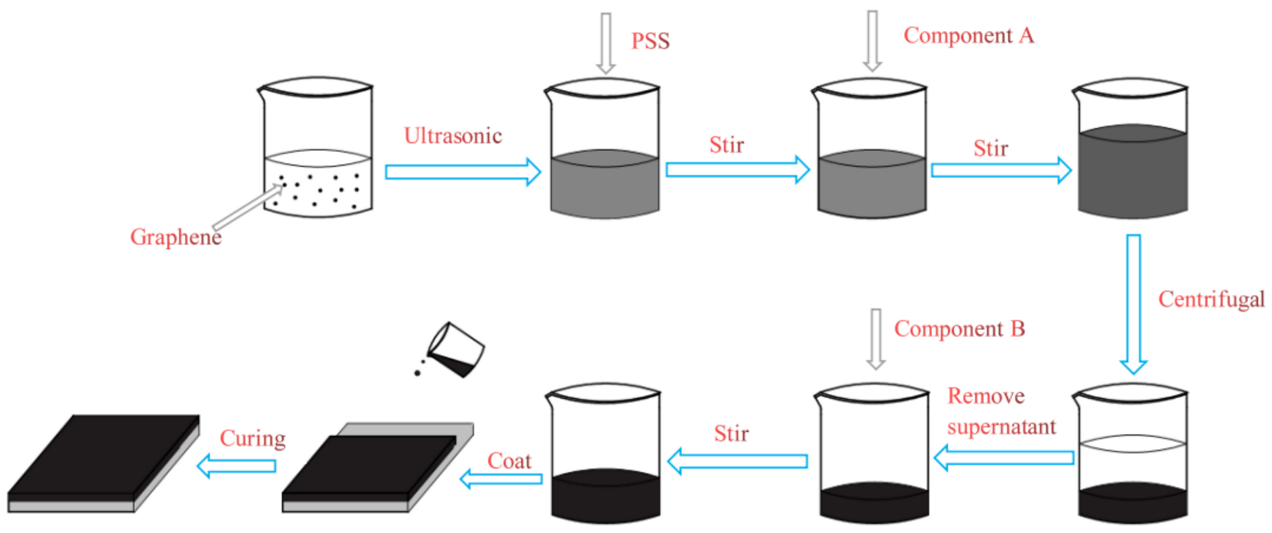
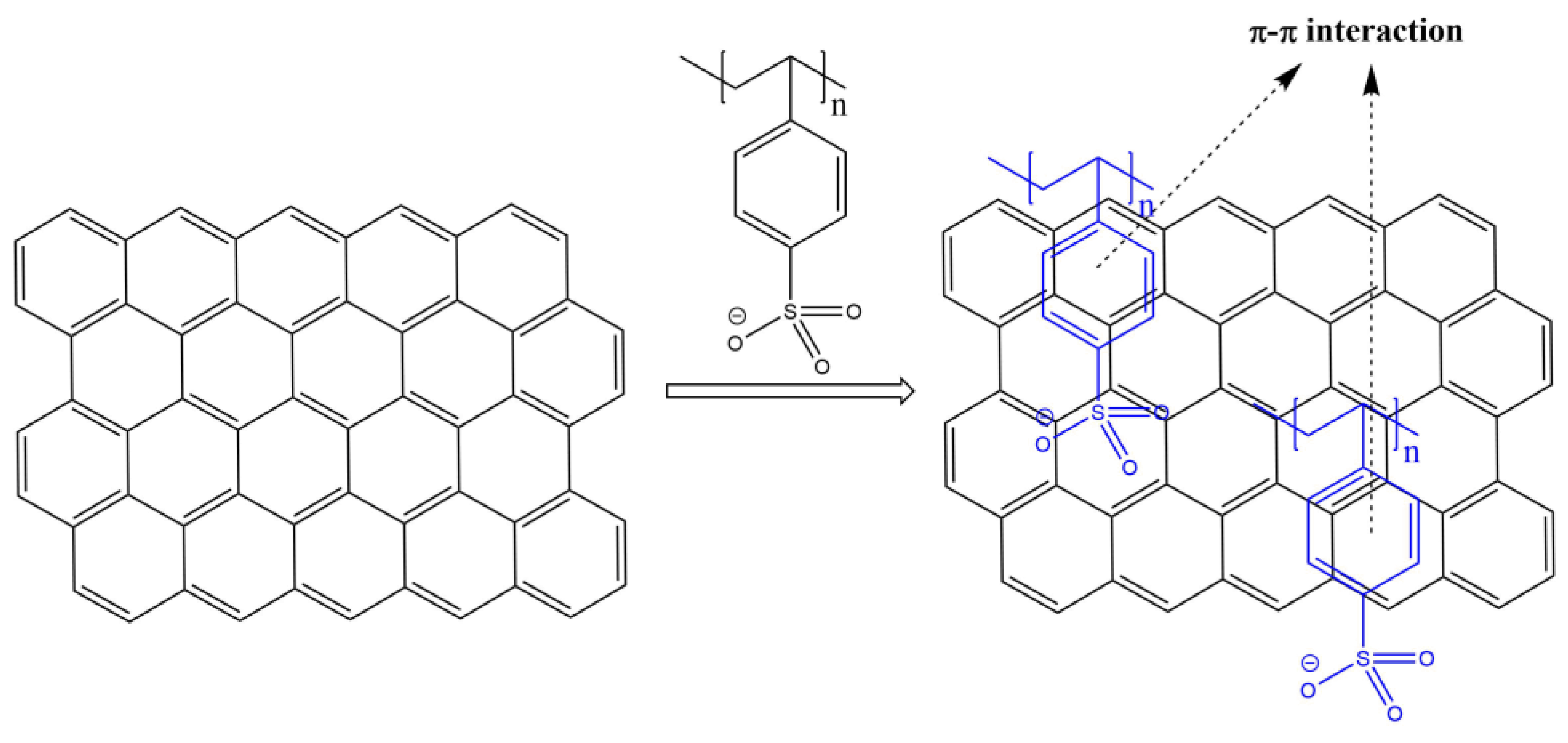
2.2. Preparation of Graphene Dispersion Modified by PSS

A 20 mg portion of graphene was dispersed in 20 mL of deionized water by cell grinder, and then the mixture was ultrasonicated for 1 h to obtain graphene dispersion solution (1 mg/mL). Then PSS was added to the mixture, the mass ratio of PSS to graphene was 20:1. The mixture was placed in a magnetic stirrer and stirred for 10 min to make the sodium polystyrene sulfonate be completely dissolved. Then the PSS-G dispersion was obtained.

2.3. Preparation of Composite Coatings

We firstly mixed PSS-G dispersion with component A of epoxy zinc-containing coating. The component A included epoxy resin, zinc powder, filler, xylene and butanol. After stirring uniformly, we put PSS-G in the centrifuge for centrifugation at a speed of 3000 rpm for 15 min. After centrifugation, mixture of the upper and lower layers was obtained, and then the transparent clarified liquid was extracted from the upper layer by disposable syringe to remove the water in the mixture. Component B of epoxy zinc-containing coating was added to the remaining substance, component B included polyamide and xylene, and then PSS-G modified epoxy zinc-containing coating was obtained by homogeneous stirring. The ratio of component A of epoxy zinc-containing coating to component B of epoxy zinc-containing coating was 10:1. The Q235 steel electrode surfaces were polished with 400/600/800/1000 mesh sandpaper before being used, then were washed with acetone and alcohol for 10 min, respectively, and then dried with clean, dust-free paper. The prepared epoxy zinc-containing coating was coated on the steel plate with wire rods. After natural air drying for 48 h, the coating with a thickness of about 20 µm was obtained. The preparation process of composite coatings is shown in Figure 1.

2.4. Characterization

Raman spectra were measured with HORIBA XpoloRA Plus (HORIBA, Paris, France ) using the wavelength of 532 nm to characterize the quality (defects and thicknesses, etc.) of graphene and PSS-G. The modification principle of PSS-G was determined by X-ray photoelectron spectroscopy (XPS, AXIS ULTRA DLD, KRATOS, Manchester, UK) with a monochromated Al Kα irradiation. Both Raman and XPS samples were prepared by depositing the corresponding dispersions on SiO2/Si substrates and drying in air. Transmission electron microscopy (TEM, JEOL JEM-2100, Tokyo, Japan) was performed to observe the morphology of PSS-G. The TEM sample was prepared by depositing the PSS-G dispersions on copper grids and drying in air. Tapping mode atomic force microscopy (AFM, Dimension, Icon-Bruker, Billerica, MA, USA) was performed to observe the morphology of PSS-G and characterize the thickness of PSS-G. The AFM samples were prepared by depositing the corresponding dispersions on glass substrates and drying in air.
The electrochemical corrosion test was performed in 3.5% NaCl solution on a PARSTAT MS electrochemical workstation. The potentiodynamic polarization curves and electrochemical impedance spectroscopy (EIS) were acquired by a classical three-electrode system at room temperature with platinum (Pt) plate, saturated calomel electrode (SCE) and coating/Q235 steel as counter electrode, reference electrode and working electrode, respectively. Potentiodynamic measurement of polarization curves was carried out within the potential range from −0.75 to 0.5 V, at a scan rate of 20 mV/s. The frequency range of EIS measurement was 1 × 10⁵ to 1 × 10⁻² Hz and the sinusoidal voltage signal amplitude was 20 mV. The test samples were prepared by encapsulating the coated Q235 steel with a mixture of paraffin and rosin, only 1cm2 of the sample surface was left for electrochemical test.
Two horizontal lines were scratched on the coated Q235 steels and the samples were exposed in the salt spray cabin for 1000 h according to GB/T 1771-2007 [18]. The salt water was sprayed on the surface of the samples in order to observe the corrosion of the samples. The salt spray cabin was purchased from Lixin Instrument Equipment Co., Ltd. (Dongguan, China), LX-6013.

3. Results and Discussion

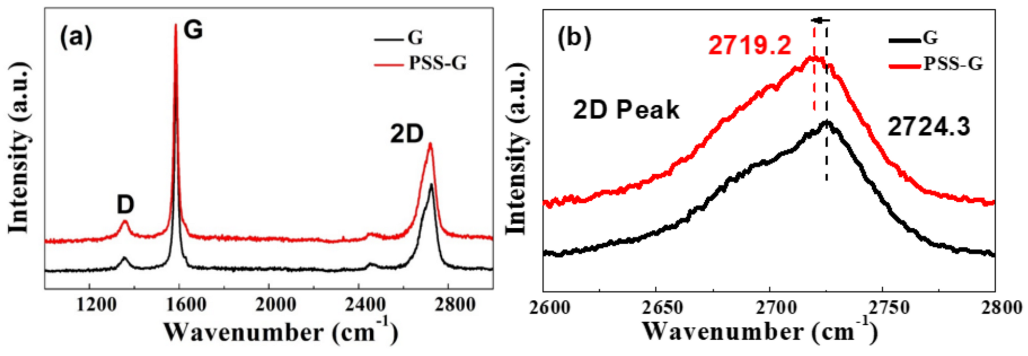
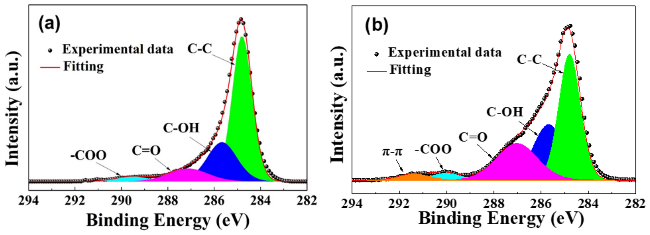
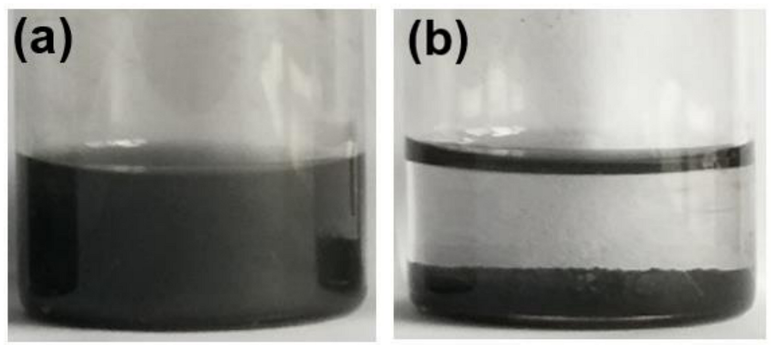
3.1. Characterization of PSS-G

The PSS-G and graphene (G) were both examined by Raman spectroscopy and the results were shown in Figure 2a, where black and red spectra show the Raman spectra of G and PSS-G, respectively. For the pure graphene (black curve), it can be seen that three characteristic peaks arose at 1356, 1582 and 2724 cm−1, which corresponded to D, G and 2D bands, respectively. The G peak was due to the in-plane bonding and contraction of carbon atoms in the sp2 orbital hybridization, indicating the symmetry and ordering of the reaction materials [19]. The D peak was the fracture mode corresponding to Brillouin Zone boundary K, which usually represents the defect of graphene [19]. Generally, the shape and position of the 2D peak can be used to judge whether graphene is single, double or multi-layered [20].
It was evident that PSS-G (red curve) indicated a quite similar feature with that of pure G. The D, G and 2D peaks also arose at 1358, 1583 and 2719 cm−1, respectively. In order to compare in more detail the two samples, Figure 2b shows the enlarged figure at the 2600–2800 cm−1 region of Figure 2a showing more detail of the 2D peaks. It can be clearly seen that the 2D peak PSS-G (red) had a red shift to 2719.2 cm−1, compared to that of pure graphene (black) at 2724.3 cm−1. Such a red shift of the 2D peak indicated that the stacking of G was weakened [20].
To further investigate the features of PSS-G, TEM and AFM characterization have been carried out. Figure 3a shows the TEM results. After depositing the PSS-G dispersions on copper grids and drying in air, it can be seen that the whole sheet of PSS-G was transparent suggesting very few layers feature of PSS-G. A few wrinkle areas (dark regions) can also be observed. Figure 3b shows a 2 × 2 µm2 AFM image of PSS-G on glass substrates, where two graphene sheets (brighter regions) can be found. Line profiles performed at the graphene vicinity, as shown in Figure 3c,d offer the direct evidence of the thickness of PSS-G sheets. It can be seen from the cross-section analysis that the thicknesses of both PSS-G sheets were about 2 nm, corresponding to about 2–3 monolayers [14,21,22]. This was consistent with the TEM result.
The results showed that PSS could be used as a dispersant to prepare high quality graphene nanoflakes with very few atomic layers.
It is significant to understand further the modification mechanism of PSS on graphene, therefore XPS experiments were performed on G and PSS-G. The C 1s XPS results are shown in Figure 4a,b for G and PSS-G, respectively. In Figure 4, black dots indicate the experimental data after subtracting a Shirley profile and the red line shows the fitting profile. Peaks with different colors reveal the fitting components. In Figure 4a for C 1s of pure graphene, the dominant peak centered at 284.8 eV (green) can be attributed to the C–C. The weak peak centered at 285.6 eV (blue), 287.2 eV (violet), 289.4 eV (cyan) correspond to the C–OH, C=O, –COO, respectively [16,23,24], which are produced in the catalytic exfoliation process of graphene. Figure 4b shows the XPS C 1s spectrum of the PSS-G. Similar to pure G, the C–C bond centered at 284.8eV dominates the spectrum. The shoulder peaks centered at 285.6 eV (blue), 287.0 eV (violet), 289.9 eV (cyan) corresponding to the C–OH, C=O, –COO are also shown. Interestingly and importantly, an additional component at 291.4 eV evidently appeared in PSS-G. This peak is related to the bond of the π−π interaction [11], which suggests that PSS modified graphene in a nonvalent manner.
As shown in Figure 5a, the PSS-G dispersion was in black solution state without agglomerated particles and the stability time of the modified graphene dispersion was 48 h, while direct dispersion of G (Figure 5b) in aqueous solution led to agglomeration and precipitation.
The stable aqueous dispersion of graphene was obtained by covalent modification of graphene. The reaction scheme between PSS and graphene is shown in Figure 6. Graphene nanosheets can be stably dispersed in water solvents with PSS as dispersant. π−π interactions are formed between the PSS and the graphene nanosheets, which prevents graphene from agglomeration.

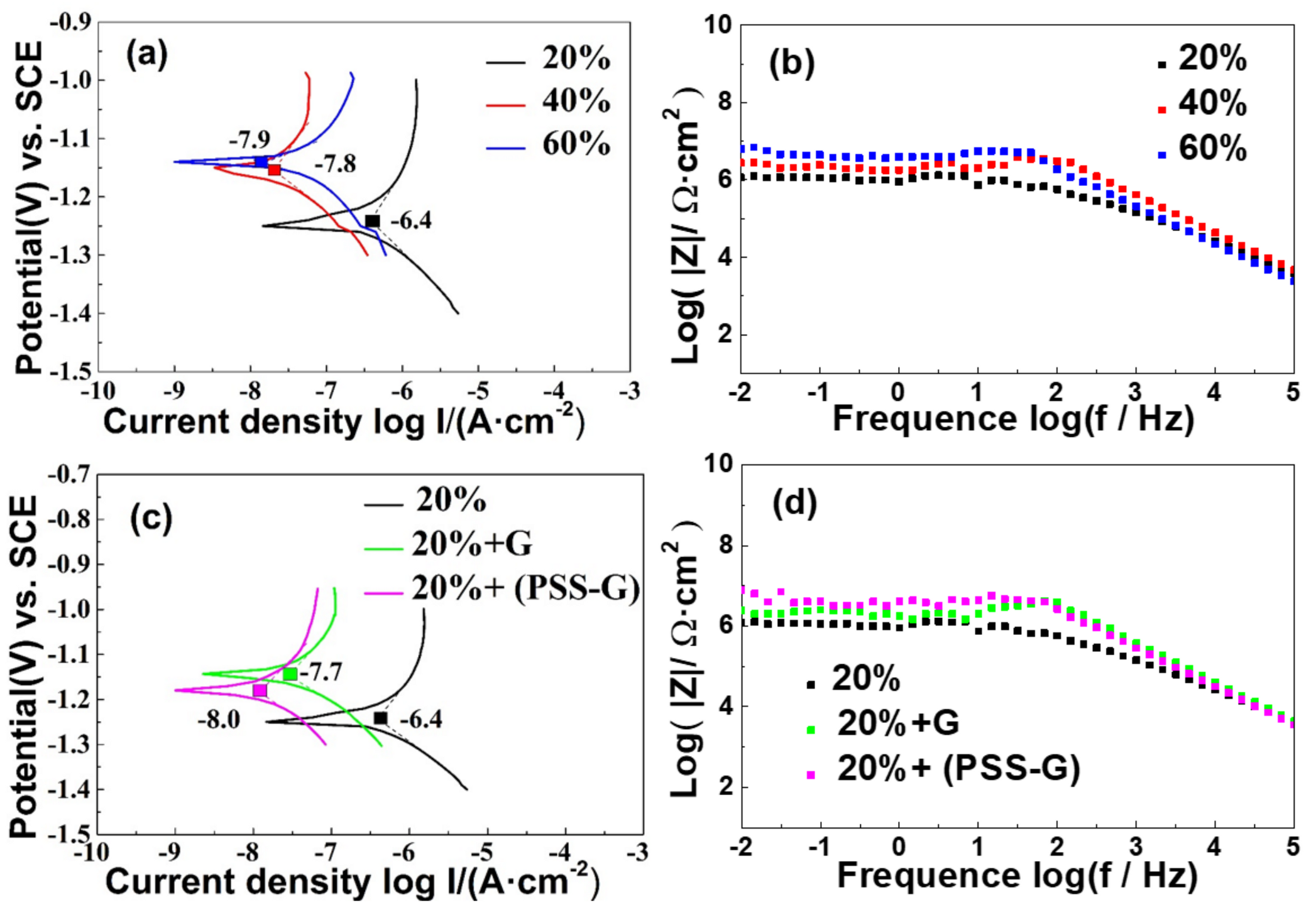
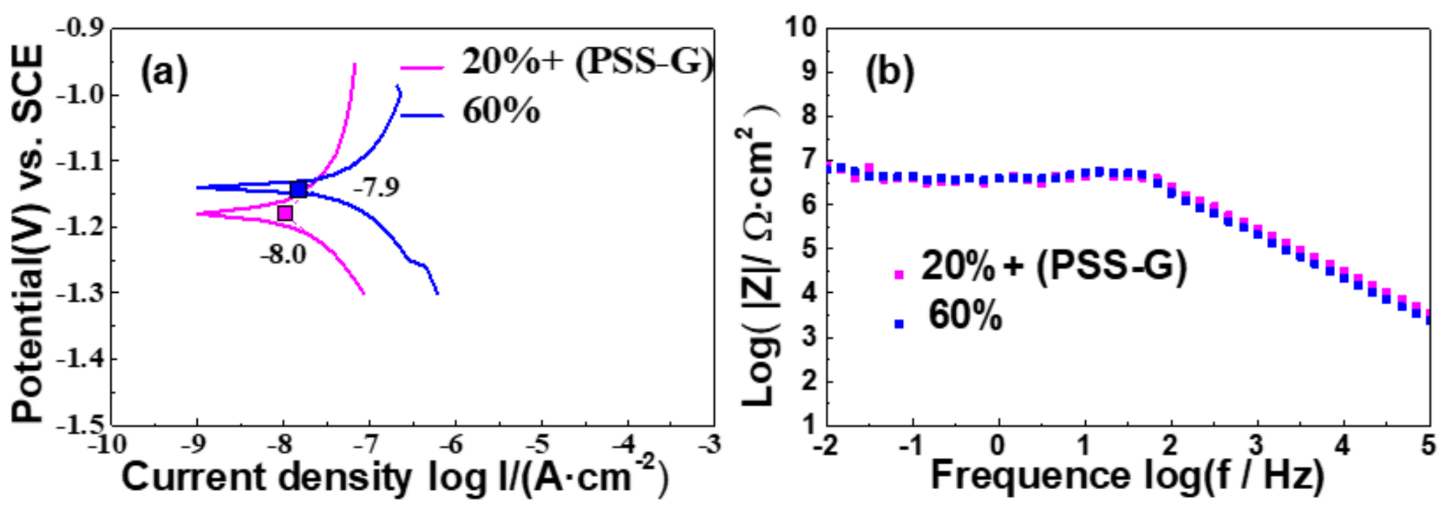
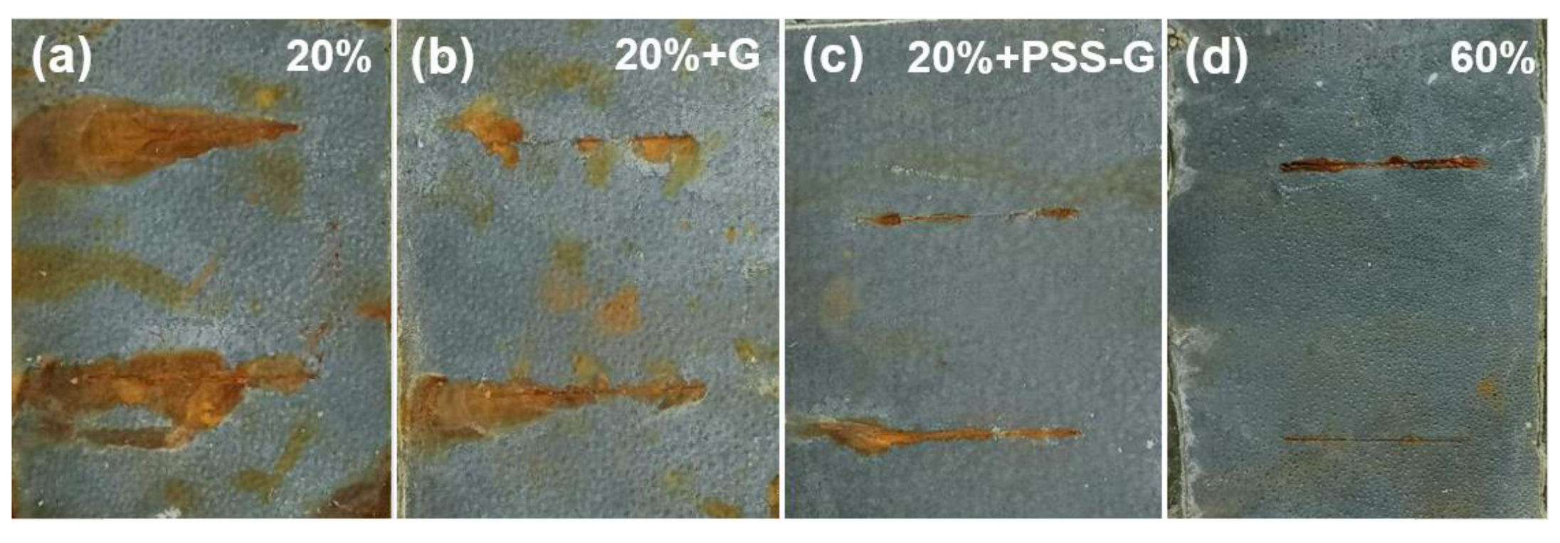
3.2. Anticorrosion Properties of PSS-G Coatings

In graphene composite epoxy zinc-containing coatings, the quality and the thickness of the graphene are important for the enhancement of anticorrosion performance. Therefore the obtained PSS-G dispersion was mixed with epoxy zinc-containing coatings to examine the impact on anticorrosion properties.
A series of zinc-containing coatings with a zinc content of 20%, 40% and 60% have been employed. In order to compare the impact of PSS-G with pure G, three types of samples, namely epoxy zinc-containing coatings, epoxy/G composite coatings, and epoxy/PSS-G composite coatings were investigated by electrochemical corrosion test. More details can be found in the Experimental section.
Figure 7a shows the potentiodynamic polarization curves of epoxy zinc-containing coatings with different zinc contents of 20% (black), 40%(red) and 60% (blue). The corrosion current density (the ratio of the self-corrosion current to the test area of the sample), Icorr, represents the intensity of the cathodic oxygen reduction and anodic dissolution of metal ions, which can represent the corrosion rate [4,25,26]. The corrosion current density of zinc-containing epoxy coatings with 20% zinc content was 3.98 × 10⁻⁷ A (log Icorr = −6.4), that of zinc-containing epoxy coatings with 40% zinc content was 1.58 × 10⁻⁸ A (log Icorr = −7.8), and that of zinc-containing epoxy coatings with 60% zinc content was 1.26 × 10⁻⁸ A (log Icorr = −7.9). It is evident that as the Zn content increases, the absolute value of corrosion current density continuously decreases, suggesting better anticorrosion performance.
EIS was carried out to further study the dielectric properties of the coatings. Figure 7b shows the Bode plots of samples exposed to 3.5 wt.% NaCl solution. Impedance modulus |Z| at low frequencies (f = 0.01Hz) can semiquantitatively characterize coating resistance [11]. The impedance modulus of zinc-containing epoxy coatings with 20% zinc content (black) was 1.17 × 10⁶ at 0.01 Hz (log |Z| = 6.07), that of zinc-containing epoxy coatings with 40% zinc content (red) was 2.75 × 10⁶ (log |Z| = 6.44), and that of zinc-containing epoxy coatings with 60% zinc content (blue) was 6.31 × 10⁶ (log |Z| = 6.80). Apparently, the impedance modulus increases as the zinc content increases.
The epoxy zinc-containing coatings with 60% zinc content had a lower corrosion current density Icorr and higher impedance modulus |Z| (f = 0.01 Hz) in comparison with the other zinc contents, indicating that the barrier properties of 60% epoxy zinc-containing coatings were better than its two counterparts.
To understand the impact of graphene dispersions on the anticorrosion performances of epoxy zinc-containing coatings, potentiodynamic polarization curves of pure epoxy zinc-containing coatings (black), epoxy/G (green) and epoxy/PSS-G coatings (violet) with 20% zinc content are shown and compared in Figure 7c. The corrosion current density Icorr of epoxy zinc-containing coatings with 20% zinc content was 3.98 × 10⁻⁷ A (log Icorr = − 6.4), that of epoxy/G coatings was 2.01 × 10⁻⁸ A (log Icorr = −7.7), and that of epoxy/PSS-G coatings was 1.00 × 10⁻⁸ A (log Icorr = −8.0). Figure 7d shows the Bode plots of the three samples. The impedance modulus |Z| of pure epoxy zinc-containing coatings (black) was 1.17 × 10⁶ (log |Z| = 6.07) at the frequency of 0.01 Hz, that of epoxy/G coat ings (green) was 2.51×10⁶ (log |Z| = 6.40) at the frequency of 0.01 Hz, and that of epoxy/PSS-G coatings (violet) was 7.94 × 10⁶ (log |Z| = 6.90) at the frequency of 0.01 Hz.
It was evident that the epoxy/PSS-G coating showed the largest impedance modulus at the lowest frequency and the lowest absolute value of self-corrosion current, suggesting that the coating had the best protection performance for metal substrate.
To further highlight the enhancement role of PSS-G dispersion on epoxy zinc-containing coatings, the properties of epoxy/PSS-G coatings with 20% zinc content (violet) and epoxy coatings with 60% zinc content (blue) are shown in Figure 8. Figure 8a reveals the potentiodynamic polarization curves of both samples. The corrosion current density of epoxy/PSS-G coatings with 20% zinc content was 1.21 × 10⁻⁸ A (log Icorr = −8.0), while that of epoxy coatings with 60% zinc content was 1.42 × 10⁻⁸ A (log Icorr = −7.9), which were very close to each other. The Bode plots in Figure 8b further illustrated that the anticorrosion properties of epoxy/PSS-G coatings with 20% zinc content and epoxy coatings with 60% zinc content were basically the same, with a very similar impedance modulus of log |Z| = 6.9.
In order to further confirm the impact of PSS-G, neutral salt spray tolerance tests for 1000 h were carried out on epoxy zinc-containing coatings with 20% zinc content, epoxy/G coatings, epoxy/PSS-G coatings and epoxy zinc-containing coatings with 60% zinc content, and the results are shown in Figure 9a–d, respectively. The salt spray tolerance of coatings could be judged by whether there were blisters or corrosion spots around the scratches on the coatings, which would reflect the corrosion resistance of the coatings [27]. There were obvious blisters, rust and corrosion spread in zinc-containing coatings with 20% zinc content (Figure 9a) and epoxy/G coatings (Figure 9b). Compared with them, the corrosion on epoxy/PSS-G coatings (Figure 9c) and epoxy zinc-containing coatings with 60% zinc content (Figure 9d) was significantly weaker. It further proved that the addition of PSS-G and the increase of zinc content could reduce corrosion from the aspect of salt spray tolerance.
Comparing epoxy/PSS-G coatings with epoxy zinc-containing coatings with 60% zinc content, there was no difference between the two samples in terms of blisters. The scratches on the top of the PSS-G/coating sample were corroded, but the spread to both sides was not obvious. The scratch on the bottom showed a slight corrosion spread of less than 1 cm. The scratch on the top of the 60% zinc content sample showed slight corrosion and spread less than 1 cm, while the scratch on the bottom showed corrosion spread, but there was no obvious spread on both sides. In conclusion, the corrosion resistance of the 60% zinc content coating sample and the PSS-G/coating sample was basically the same after 1000 h.

4. Conclusions

In conclusion, stable graphene solution was obtained by direct noncovalent modification using PSS. The 2D Raman peak of PSS modified graphene shifted from 2724.3 to 2719.2 cm−1, indicating that the number of graphene layers decreased after the modification. The whole sheet of PSS-G was transparent under TEM, which confirmed the Raman results. AFM results directly confirmed that the thickness of graphene was 2 nm, about 2–3 layers. The results of XPS showed that there were five peaks in PSS-G, which centered at 284.8, 285.6, 287.0, 289.9, and 291.4 eV corresponding to the C–C, C–OH, C=O, –COO and π–π bonds, respectively. The combination of Raman, TEM, AFM and XPS results showed that the PSS-G had a thickness of only 2–3 monolayers and strong π–π interaction between PSS and graphene sheets. According to the electrochemical results, the epoxy zinc coating with modified graphene had better corrosion resistance than the pure epoxy zinc coating, and the addition of graphene with 0.05% by weight can reduce the zinc content from 60% to 20% without degradation of anticorrosion performance, which was further confirmed by the neutral salt spray experiment after 1000 h. The addition of PSS directly modified graphene in an epoxy zinc coating can not only improve the anticorrosion performance, but also may have potential applications in other fields such as batteries.

Author Contributions

Conceptualization, G.N.; methodology, G.N. and W.B.; investigation, W.B., Y.M., J.L., C.Q. and R.A.; resources, Q.X. and J.Z.; data curation, J.L., W.B., Y.M., C.Q. and R.A.; writing—original draft preparation, J.L.; writing—review and editing, G.N.; visualization, J.L.; supervision, W.R.; project administration, W.R.; funding acquisition, G.N. and Q.X. All authors have read and agreed to the published version of the manuscript.

Funding

This research was funded by Key Research Project of Shaanxi Province of China, grant number 2018ZDXM-GY-150 and 2020GY-271; Natural Science Foundation of China, grant number 51602247; the Fundamental Research Funds for the Central Universities, the “111 Project” of China (B14040). The APC was funded by Key Research Project of Shaanxi Province of China (2018ZDXM-GY-150).

Conflicts of Interest

The authors declare no conflict of interest.

References

  1. Hayatdavoudi, H.; Rahsepar, M. A mechanistic study of the enhanced cathodic protection performance of graphene-reinforced zinc rich nanocomposite coating for corrosion protection of carbon steel substrate. J. Alloys Compd. 2017, 727, 1148–1156. [Google Scholar] [CrossRef]
  2. Marchebois, H.; Touzain, S.; Joiret, S.; Bernard, J.; Savall, C. Zinc-rich powder coatings corrosion in sea water: Influence of conductive pigments. Prog. Org. Coat. 2002, 45, 415–421. [Google Scholar] [CrossRef]
  3. Kirkland, N.T.; Schiller, T.; Medhekar, N.; Birbilis, N. Exploring graphene as a corrosion protection barrier. Corros. Sci. 2012, 56, 1–4. [Google Scholar] [CrossRef]
  4. Chang, C.-H.; Huang, T.-C.; Peng, C.-W.; Yeh, T.-C.; Lu, H.-I.; Hung, W.-I.; Weng, C.-J.; Yang, T.-I.; Yeh, J.-M. Novel anticorrosion coatings prepared from polyaniline/graphene composites. Carbon 2012, 50, 5044–5051. [Google Scholar] [CrossRef]
  5. Cui, G.; Bi, Z.; Zhang, R.; Liu, J.; Yu, X.; Li, Z. A comprehensive review on graphene-based anti-corrosive coatings. Chem. Eng. J. 2019, 373, 104–121. [Google Scholar] [CrossRef]
  6. Yu, Y.-H.; Lin, Y.-Y.; Lin, C.-H.; Chan, C.-C.; Huang, Y.-C. High-performance polystyrene/graphene-based nanocomposites with excellent anti-corrosion properties. Polym. Chem. 2014, 5, 535–550. [Google Scholar] [CrossRef]
  7. Sahu, S.C.; Samantara, A.K.; Seth, M.; Parwaiz, S.; Singh, B.P.; Rath, P.C.; Jena, B.K. A facile electrochemical approach for development of highly corrosion protective coatings using graphene nanosheets. Electrochem. Commun. 2013, 32, 22–26. [Google Scholar] [CrossRef]
  8. Allen, M.J.; Tung, V.C.; Kaner, R.B. Honeycomb carbon: A review of graphene. Chem. Rev. 2010, 110, 132–145. [Google Scholar] [CrossRef]
  9. Randviir, E.P.; Brownson, D.A.C.; Banks, C.E. A decade of graphene research: Production, applications and outlook. Mater. Today 2014, 17, 426–432. [Google Scholar] [CrossRef]
  10. Texter, J. Graphene dispersions. Curr. Opin. Colloid Interface Sci. 2014, 19, 163–174. [Google Scholar] [CrossRef]
  11. Chen, C.; Qiu, S.; Cui, M.; Qin, S.; Yan, G.; Zhao, H.; Wang, L.; Xue, Q. Achieving high performance corrosion and wear resistant epoxy coatings via incorporation of noncovalent functionalized graphene. Carbon 2017, 114, 356–366. [Google Scholar] [CrossRef]
  12. Shih, C.-J.; Lin, S.; Strano, M.S.; Blankschtein, D. Understanding the stabilization of liquid-phase-exfoliated graphene in polar solvents: Molecular dynamics simulations and kinetic theory of colloid aggregation. J. Am. Chem. Soc. 2010, 132, 14638–14648. [Google Scholar] [CrossRef] [PubMed]
  13. Hernandez, Y.; Nicolosi, V.; Lotya, M.; Blighe, F.M.; Sun, Z.; De, S.; McGovern, I.T.; Holland, B.; Byrne, M.; Gun’Ko, Y.K.; et al. High-yield production of graphene by liquid-phase exfoliation of graphite. Nat. Nanotechnol. 2008, 3, 563–568. [Google Scholar] [CrossRef] [PubMed] [Green Version]
  14. Bai, H.; Xu, Y.; Zhao, L.; Li, C.; Shi, G. Non-covalent functionalization of graphene sheets by sulfonated polyaniline. Chem. Commun. 2009, 13, 1667–1669. [Google Scholar] [CrossRef]
  15. Chang, H.; Wang, G.; Yang, A.; Tao, X.; Liu, X.; Shen, Y.; Zheng, Z. A transparent, flexible, low-temperature, and solution-processible graphene composite electrode. Adv. Funct. Mater. 2010, 20, 2893–2902. [Google Scholar] [CrossRef]
  16. Stankovich, S.; Piner, R.D.; Chen, X.Q.; Wu, N.Q.; Nguyen, S.T.; Ruoff, R.S. Stable aqueous dispersions of graphitic nanoplatelets via the reduction of exfoliated graphite oxide in the presence of poly(sodium 4-styrenesulfonate). J. Mater. Chem. 2006, 16, 155–158. [Google Scholar] [CrossRef]
  17. Kratochvílová, I.; Ashcheulov, P.; ÅkarohlÃd, J.; Škoda, R.; Kopeček, J.; Sajdl, P.; Macák, J.; Lajčinová, M.; Nováková, A.; Neethling, J.; et al. Zr alloy protection against high-temperature oxidation: Coating by a double layered structure with active and passive functional properties. Corros. Sci. 2020, 163, 108270. [Google Scholar] [CrossRef]
  18. GB/T 1771-2007. Paints and Varnishes-Determination of Resistance to Neutral Salt Spray(fog); Standardization Administration of China: Beijing, China, 2007. [Google Scholar]
  19. Ferrari, A.C.; Robertson, J. Interpretation of Raman spectra of disordered and amorphous carbon. Phys. Rev. B. 2000, 61, 14095–14107. [Google Scholar] [CrossRef] [Green Version]
  20. Ferrari, A.C.; Meyer, J.C.; Scardaci, V.; Casiraghi, C.; Lazzeri, M.; Mauri, F.; Piscanec, S.; Jiang, D.; Novoselov, K.S.; Roth, S.; et al. Raman spectrum of graphene and graphene layers. Phys. Rev. Lett. 2006, 97, 187401. [Google Scholar] [CrossRef] [Green Version]
  21. Xu, Y.; Bai, H.; Lu, G.; Li, C.; Shi, G. Flexible graphene films via the filtration of water-soluble noncovalent functionalized graphene sheets. J. Am. Chem. Soc. 2008, 130, 5856–5857. [Google Scholar] [CrossRef]
  22. Kuila, T.; Bose, S.; Mishra, A.K.; Khanra, P.; Kim, N.H.; Lee, J.H. Chemical functionalization of graphene and its applications. Prog. Mater. Sci. 2012, 57, 1061–1105. [Google Scholar] [CrossRef]
  23. Trung Dung, D.; Lee H-i Jeong, H.M.; Kim, B.K. Direct covalent modification of thermally exfoliated graphene forming functionalized graphene stably dispersible in water and poly(vinyl alcohol). Colloid Polym. Sci. 2013, 291, 2365–2374. [Google Scholar]
  24. Gao, J.; Liu, F.; Liu, Y.; Ma, N.; Wang, Z.; Zhang, X. Environment-friendly method to produce graphene that employs vitamin C and amino acid. Chem. Mater. 2010, 22, 2213–2218. [Google Scholar] [CrossRef]
  25. Kear, G.; Barker, B.D.; Walsh, F.C. Electrochemical corrosion of unalloyed copper in chloride media—A critical review. Corros. Sci. 2004, 46, 109–135. [Google Scholar] [CrossRef]
  26. Li, P.; He, X.; Huang, T.-C.; White, K.L.; Zhang, X.; Liang, H.; Nishimura, R.; Sue, H.J. Highly effective anti-corrosion epoxy spray coatings containing self-assembled clay in smectic order. J. Mater. Chem. A 2015, 3, 2669–2676. [Google Scholar] [CrossRef]
  27. Ramezanzadeh, B.; Niroumandrad, S.; Ahmadi, A.; Mahdavian, M.; Moghadam, M.H.M. Enhancement of barrier and corrosion protection performance of an epoxy coating through wet transfer of amino functionalized graphene oxide. Corros. Sci. 2016, 103, 283–304. [Google Scholar] [CrossRef]
Figure 1. Schematic illustration of the preparation process of the composite coatings.
Coatings 10 01150 g001
Figure 2. (a) Raman spectra of G, PSS-G hybrid; (b) the enlarged 2D-band regions; (the black line is for G, the red line is for PSS-G).
Coatings 10 01150 g002
Figure 3. Morphology of PSS-G. (a) TEM images of PSS-G; (b) AFM images of PSS-G; height profiles of the PSS-G in (c) the blue circled region and (d) the red circled region shown in (b).
Coatings 10 01150 g003
Figure 4. XPS spectra in the C 1s region of (a) G and (b) PSS-G.
Coatings 10 01150 g004
Figure 5. Optical images of 1mg/mL (a) PSS-G and (b) G dispersed in water after 48 h.
Coatings 10 01150 g005
Figure 6. Schematic diagram of the reaction process.
Coatings 10 01150 g006
Figure 7. (a,c) Tafel polarization curves and (b,d) Bode plots of coatings with different zinc contents, pure coating, G/coating and PSS-G/coating with 20% zinc content. (The black line, red line, blue line are for the zinc-containing coatings with zinc content of 20%, 40% and 60%, respectively. The green line is for epoxy/G coating, the violet line is for epoxy/PSS-G coating).
Coatings 10 01150 g007
Figure 8. (a) Tafel polarization curves and (b) Bode plots of the pure coating with 60% zinc contents and PSS-G/coating with 20% zinc contents. (The blue line is for zinc-containing coating with zinc content of 60%, the violet line is for epoxy/PSS-G coatings).
Coatings 10 01150 g008
Figure 9. Visual performance of the epoxy zinc-containing coatings with (a) 20% zinc content, (b) epoxy/G coatings, (c) epoxy/PSS-G coatings and (d) epoxy zinc-containing coatings with 60% zinc content exposed to neutral salt spray for 1000 h.
Coatings 10 01150 g009
Publisher’s Note: MDPI stays neutral with regard to jurisdictional claims in published maps and institutional affiliations.

