Article

Investigation of the Influence of Microdroplets on the Coatings Nanolayer Structure

1
VTO Department, Moscow State Technological University STANKIN, 127994 Moscow, Russia
2
IDTI RAS, 127994 Moscow, Russia
3
Materials Science and Metallurgy Shared Use Research and Development Center, National University of Science and Technology MISiS, 119049 Moscow, Russia
4
Department of Solid State Physics and Nanosystems, National Research Nuclear University MEPhI, 115409 Moscow, Russia
*
Author to whom correspondence should be addressed.
Coatings 2020, 10(12), 1204; https://doi.org/10.3390/coatings10121204
Submission received: 3 November 2020 / Revised: 2 December 2020 / Accepted: 8 December 2020 / Published: 10 December 2020
(This article belongs to the Special Issue Technologies of Coatings and Surface Hardening for Tool Industry)

Abstract

:
The paper presents the results of studies focused on the specific features typical for the formation of the shape and structure of microdroplets embedded into the structure of the Ti–TiN–(Ti,Cr,Mo,Al)N and Ti–TiN–(Ti,Al,Nb,Zr)N coatings during their deposition. Three main microdroplet shapes—a sphere, a tear, and a lens—have been considered. The specific features typical for the formation of secondary layered structures on the surface of some microdroplets have also been examined. As a result of the conducted investigations, with the use of scanning and transmission electron microscopy, the influence of microdroplets on the distortion of the nanolayer structure of the coatings was studied. A hypothesis has been proposed concerning a relationship between the microdroplet shape and the presence or absence of secondary structures and the microdroplet sizes and weight, as well as the conditions in the unit chamber during the movement of a microdroplet from a cathode to the deposition surface. Based on the study focused on the shape of the microdroplet core and the specific features typical for the formation of the secondary structure around it, a hypothesis has been proposed, according to which, for some microdroplets, it takes much more time than previously assumed for the movement from a cathode to the deposition surface.

1. Introduction

As is known, the formation of microdroplets and their penetration into the structures of modifying coatings are a significant problem, typical of the physical vapour deposition (PVD) method [1,2,3,4,5]. Technologies and equipment—from simple arrays to complex magnetic traps—are being actively developed and used to significantly reduce the number of microdroplets [6,7,8,9,10,11,12]. At the same time, the process of the formation of microdroplets and their influence on the coating structure are being studied. In particular, it has been found that the number and mean size of microdroplets increase simultaneously with an increase in the discharge current, the gas pressure, and temperature of the cathode surface [13,14,15,16]. In [13,16,17], it is noted that the microdroplet shapes vary, and microdroplets can be classified into three groups, defined as sphere-, lens-, and tear-shaped microdroplets. The number of microdroplets decreases with an increase in the temperature of the substrate [18]. The processes of microdroplet formation and penetration into the coating structure has been studied mainly by using mathematical modeling methods. In several papers, the studies were focused on the mechanism of microdroplet deformation upon hitting a substrate in various deposition conditions. In [19], the cooling of a liquid microdroplet is modeled using the laws of hydrodynamics and assuming an ideal interphase thermal contact. The Lagrangian concept and the hydrodynamic model of Fukai et al. [20] were used to simulate the heat transfer in a microdroplet and a substrate. Wadvogel et al. [21,22] expanded the specified model, taking into account the solidification process and the incomplete interphase thermal contact. Several studies separately consider the role of incomplete thermal contact between a substrate and a microdroplet, which is an essential parameter in the process of heat transfer. In particular, Liu et al. [23] suggest that no ideal thermal contact between a microdroplet and a substrate can be achieved because of the roughness of the substrate surface, the surface tension of the microdroplet, the presence of surface impurities, and gas entrapment. Heat transfer in the real area of contact between the droplet and the substrate surface occurs both due to thermal conductivity and, to some extent, radiation [24]. For microdroplets of molten lead and similar materials used for brazing, the incomplete thermal contact was investigated in [25,26,27] through experiments. In particular, it was found that the incomplete thermal contact affects the microdroplet shape, and their height relative to the substrate can change by 20% due to changes in the thermal contact resistance. Some values of the interphase heat transfer coefficients for specific pairs of materials were determined both by calculations and experiments in [28]. It was found that the interphase heat transfer coefficient noticeably influences the microdroplet solidification process. In [29], the study focused on the modeling of a liquid microdroplet with the diameter of 80 µm that moved with a velocity of 5 m/s and hit a flat solid surface. Given that the conditions under consideration differ from the coating deposition conditions, this model can be useful, since the general nature of the physical conditions (sizes of the microdroplet, its movement velocity, and penetration of the liquid microdroplet into the solid surface) correlates well with the challenge under consideration. In [29], the investigation also takes into account the possible variance of the heat transfer coefficient over time. In [30], the studies simulate a hollow microdroplet, consisting of a liquid shell enclosing a gas cavity and hitting a solid flat surface. The studies demonstrate that the deformation nature of a hollow microdroplet, upon impact with a solid flat surface, differs significantly from the deformation of a filled microdroplet. In [31], the studies simulate the influence of parameters—such as the microdroplet velocity on impact, the relative distances between two successive microdroplets of molten metal, the substrate temperature, and the microdroplet sizes—on the morphology of the final shape of a microdroplet solidified after the impact. The mechanisms of the microdroplet formation are also considered in detail in [1,32,33]. All the simulation results presented indicate that upon contact of a liquid or highly ductile microdroplet with the deposition surface, the microdroplet is subjected to deformation, and it forms a typical lens-shaped structure, sometimes with a torus-shaped formation along the microdroplet boundaries. All the above papers consider the microdroplet as a liquid or highly ductile substance which does not change during the process of movement from a source to the deposition surface. At the same time, the monitoring proves that a coating structure can include not only lens-shaped microdroplets, but also microdroplets of an almost ideal spherical shape. Such a microdroplet could form only during the cooling until it contacts the deposition surface, otherwise, the microdroplet would have been inevitably deformed.
In [34], Anders considered, in sufficient detail, the issues concerning the formation of microdroplets, their movement from a cathode to a deposition surface, and their effect on the coating structure. In particular, the paper notes that microdroplets can move along trajectories that are different from a simple rectilinear trajectory, and they can repeatedly bounce off the deposition surface. Meanwhile, only the trajectories of large (macro-) droplets of tens of µm can be visually traced. In [34], it is also noted that upon hitting a deposition surface, most of the microdroplets take a donut-like shape; however, some microdroplets (according to the author, the microdroplets with the diameter less than 0.5 µm) solidify before they hit the deposition surface and take a spherical shape. A microdroplet moves in the nitrogen environment, and accordingly, a nitride shell is formed on the microdroplet surface. This is one of the possible reasons for the formation of a solid microdroplet with a regular spherical shape. For example, while moving in the nitrogen environment, a liquid titanium microdroplet can form a shell of TiN, since the melting point of titanium nitride (2930 °C) is much higher than that of pure titanium (1668 °C). As a result, the microdroplet reaching the deposition surface can have a solid nitride shell.
Multicomponent coatings based on nitrides of metals such as Ti, Al, Cr, Mo, Nb, and Zr were analyzed in a large number of studies. In particular, a number of studies have focused on the properties of the (Zr,Nb)N coating, in which a cubic fcc-(Zr,Nb)N mixed crystal phase has been detected as the dominant one [35,36,37,38]. The (Ti,Zr)N coating has also been investigated in a number of papers [39,40,41,42,43,44,45,46,47]. In [39,40,41], the presence of two cubic phases of fcc-TiN and fcc-ZrN has been detected. Meanwhile, the phase of (Ti,Zr)N (solid solution of Zr in fcc-TiN) is dominating [42,43,44,45]. It should also be noted that the hardness and heat resistance of the (Ti,Zr)N coating are significantly higher than those of TiN or ZrN [43,46,47]. The (Ti,Mo)N and (Ti,Cr)N coatings have been studied in [48,49,50,51,52]. In particular, in [48,49], the studies have revealed that the phase of fcc-TiN with Mo dissolved in it dominates in the (Ti,Mo)N coating. An important advantage of the coatings containing Cr and Mo, is their ability to form the dense oxide films (based on Magneli phases) at elevated temperatures, and these films perform tribological and protective functions [50,51,52]. The studies focused on the (Cr,Mo)N coating have detected the formation of a solid solution of Mo in fcc-CrN [53,54]. In [55], the formation of the tribological films of MoO3 and Cr2O3 has been revealed, with the oxide of MoO3 having a key effect on the reduction in friction. The properties of four-component coatings based on metals of the indicated elements have also been investigated. In particular, the study focused on the properties of the (Ti,Al,Zr)N coating has found the presence of a multiphase structure with a dominant phase based on fcc-TiN with dissolved Al and Zr, but phases of Zr3A1N, Ti3A1N, and A1N have also been detected [56,57]. The coating of (Ti,Al,Mo)N has also been studied in [58,59,60,61,62], MoNAl and Mo in fcc-TiN with the presence of an insignificant amount of MoN phase. The results of the studies performed demonstrate that the multicomponent coatings based on a solid solution of such elements as Cr, Mo, Al, Nb, and Zr in fcc-TiN can significantly increase the hardness, wear and heat resistance.
This study deals with the formation of a microdroplet phase in the coatings of Ti–TiN–(Ti,Cr,Mo,Al)N and Ti–TiN–(Ti,Al,Nb,Zr)N. Earlier, other coatings with similar compositions, including Cr,Mo–(Cr,Mo,Zr,Nb)N–(Cr,Mo,Zr,Nb,Al)N, Cr,Mo–(Cr,Mo)N–(Cr,Mo,Al)N, and Zr,Nb–(Zr,Nb)N–(Zr,Nb,Al)N, had been considered, and they proved to have good mechanical properties, while cutting tools with these coatings demonstrated good cutting properties [60]. Meanwhile, the current study is focused on microdroplets embedded into the structure of the coatings under consideration. It should be noted that the investigation of microdroplets in their dynamic state (while they are moving from a cathode to the deposition surface) is a hard-hitting challenge due to their microscopic sizes, stochastic trajectory of motion, and difficulties in observing in conditions of plasma flow. Accordingly, there are two possible ways to study the above objects, that is, to study solidified microdroplets in the coating structure and to apply methods of mathematical modeling. It should be noted that the development of an adequate model for the motion of a microdroplet is another hard-hitting challenge, taking into account a number of stochastic factors affecting the process.

2. Materials and Methods

To deposit coatings, a VIT-2 unit (VIT—IDTI RAS, Moscow, Russia) was used, which implemented the filtered cathodic vacuum arc deposition (FCVAD) technology [5,63,64,65,66,67,68,69].
Three cathode systems were used, in which cathodes of Al 99.1 at.%, Ti 99.9 at.%, and, depending on the type of the coating to be deposited, Cr–Mo (50:50 at.%) or Zr–Nb (50:50 at.%) were installed, respectively. Cathodes of cylindrical shape with a diameter of 80 mm were used.
The parameters for the process of coating deposition are presented in Table 1.
Due to the fact that the VIT-2 unit uses a micro-droplet reduction system, the droplets in the coating stemming from the Al-cathode are reduced by up to 98% [5,70] and the droplets in the coating stemming from the other cathodes are reduced by up to 85% [71,72,73]. Microdroplets in the structure of the coatings under study are rather rare. The sizes of the detected microdroplets based on Mo, Cr, Ti, and Zr–Nb usually do not exceed 3 µm (individual microdroplets up to 12 µm in size are rarely observed), because larger microdroplets are separated and do not enter a product (several sources consider the mean microdroplet size of 10–25 µm [1,2]). Samples were subjected to the microstructural studies using an SEM FEI Quanta 600 FEG (SEM 1, Waltham, MA, USA) and a Carl Zeiss EVO 50 with a Bruker energy-dispersive spectrometer (SEM 2, Billerica, MA, USA). A high-resolution transmission electron microscope (HR TEM) JEM 2100 (JEOL, Tokyo, Japan) at an accelerating voltage of 200 kV was used to investigate the coating nanostructure. The analysis of the elemental composition of the coatings was conducted at TEM using the EDX system INCA Energy (OXFORD Instruments, Abingdon, UK) in STEM (scanning transmission electron microscopy) mode. A Strata FIB 205 (FEI) was used to prepare TEM samples.

3. Results and Discussion

The available results from studies of the microstructure of coatings of various compositions and architecture, show that the detected microdroplets can be classified by several parameters (for example, by the shape of a microdroplet and its position in the coating structure) [13,74,75,76]. Accordingly, the influence of various microdroplet types on the structure of the coating and its fracture pattern also differ. In particular, the stage of the coating deposition process, at which a microdroplet is embedded into the coating structure, has a significant effect. A microdroplet can be embedded at the initial stage of the deposition process, and in such case, it often directly adheres to the substrate surface. A microdroplet can be embedded into the coating structure during the formation of a sequence of nanolayers. Finally, a microdroplet can be formed at the finishing stage of the deposition process. In such case, it penetrates into the coating surface and, since the coating has not yet cooled down and stays considerably ductile, forms a crater around itself and thus, deforms the coating structure. It should be noted that it is very difficult to directly study the process of the formation of a microdroplet, its movement inside the chamber, and penetration into the coating structure because of the small sizes of the microdroplets, their high movement velocity (which varies in the range of 6–120 m/s [1] (according to other data, 100–1000 m/s, depending on the temperature and the evaporated material [16,17]) and the complicated monitoring in the conditions of a plasma flow. Thus, at present, there are only two available ways to study the dynamics of microdroplet development, i.e., mathematical modeling and the study of solidified microdroplets and their effect on the coating structure. Microdroplets can also be classified by their final shape, which may indicate their state at the moment of impact onto the coating. In particular, there are microdroplets of an almost ideal spherical shape, due to which it can be concluded that the microdroplets have been embedded into the coating structure in a solidified state, otherwise their noticeable deformation would be inevitable. At the same time, there are lens-shaped microdroplets. This shape is typical for a microdroplet hitting the surface in a molten (liquid) state. Finally, there are microdroplets of a transition shape, that is, with signs of noticeable deformation or drop-shaped, which may indicate that at the moment of its penetration into the coating, the microdroplet was no longer liquid, but still was considerably ductile. Let us consider in more detail the structure and shapes of microdroplets of various metals. Since microdroplets of Al are almost completely separated during the deposition process, they could not be detected in the structure of the coatings, despite the fact that Al is contained in the compositions of all the coatings under study.
The structure of a microdroplet embedded into the structure of the Ti–TiN–(Ti,Cr,Mo,Al)N coating was considered. The images reveal (Figure 1) the sections of several clearly pronounced areas with noticeably different crystal sizes, which can indicate the stages of the microdroplet structure formation during the cooling process. Their formation, presumably, occurred during the microdroplet movement from the cathode towards the deposition surface and during the penetration of the microdroplet into the coating structure. The microdroplet core is formed mainly by molybdenum and chromium (Figure 1c). Area I with grains of extremely small sizes (about 3–5 nm) was formed around the microdroplet core. Then areas II and III were formed, and the grain sizes in each new area were noticeably larger than in the previous one (of about 20–40 nm in area III). Presumably, all the three areas form around the core when a microdroplet is moving from the cathode towards the deposition surface, until it hits the surface. The cooling rate of the microdroplet substance is related to the thermal conductivity coefficient (see Table 2). Since aluminium Al and molybdenum Mo are characterized by the highest thermal conductivity, while titanium Ti and zirconium Zr by the lowest thermal conductivity, the probability of the solidification of a microdroplet before its contact with the surface is higher for microdroplets of Al and Mo than for microdroplets of Ti and Zr. The size of a microdroplet and the length of its trajectory from the cathode to the deposition surface are essential. In the microdroplet, the core is formed mainly by Mo and Cr (Figure 1d), while the microdroplet composition also includes Ti and Al. Since the composition of the Mo–Cr cathode does not include Ti and Al, their presence in the microdroplet can be explained by their deposition on the microdroplet surface during its movement from the cathode to the deposition surface.
Let us consider the differences in the selected area electron diffraction (SAED) pattern for the coating structure (Figure 1e) and the microdroplet structure (Figure 1f). The analysis of the SAED pattern for the Ti–TiN–(Ti,Cr,Mo,Al)N coating (Figure 1e) finds the presence of a basic phase of (Cr,Ti,Mo,Al)N with the space group of Fm 3 ¯ m and a small amount of AlN (given the intensity of the rings) with the space group of P6.3mc. The SAED pattern for the coating demonstrates the broadening of the rings, related to the (Cr,Ti,Mo,Al)N phase. This broadening apparently arises due to the presence of polycrystalline grains formed by several types of nitrides with the same space group Fm 3 ¯ m, but with slightly different interplanar spacings for the general interference indices (Miller indices, HKL). Table 3 contains the values of interplanar spacings d (for the first six HKL indices) for the nitrides forming the Ti–TiN–(Ti,Cr,Mo,Al)N coating under study.
Table 3 also contains the interplanar spacings calculated under the SAED pattern for area B of the microdroplet under the study (Figure 1f). The SAED pattern for the microdroplet (area B) exhibits two differences compared to the SAED pattern for area A of the coating. Firstly, the SAED pattern for the microdroplet includes no AlN phase reflections, and, secondly, there is no noticeable broadening of the SAED rings. No broadening indicates that ether a certain nitride phase dominates in amount, or there are several nitride phases with very close values of d. Table 3 demonstrates that the calculated interplanar spacings correspond most closely to Mo2N (Fm 3 ¯ m). During the comparison of the elemental compositions of the coating and of the microdroplet, it can be noticed that in the region of the microdroplet, the amount of titanium decreases, and the amount of molybdenum noticeably increases, while the amount of chromium remains approximately the same. Based on the data obtained during the study of the microdroplet (investigation of its interplanar spacings and elemental composition), it can be assumed that the two phases—chromium nitride and molybdenum nitride—with considerably close interplanar spacings most likely appear in this region.
Thus, the microdroplet consists of chromium and nitrogen nitrides and not of pure metals. The above may confirm the hypothesis about the formation of a hard shell of a microdroplet due to the formation of nitrides that are more refractory than pure metal [34]. However, in this case, not only the shell of the microdroplet, but almost the entire microdroplet consists of nitrides, since the SAED pattern exhibits no rings associated with Cr or Mo.
The study of other examples showing how microdroplets of nearly spherical shape penetrate into the coating structure (Figure 2) reveals certain consistent patterns. Like in the case considered earlier, there is a microdroplet core with a fairly regular spherical shape, and the secondary structures, clearly distinguishable in Figure 2a,b, are formed around the microdroplet core. It should be noted that such a secondary structure is being formed around the microdroplet core not only on the side facing the cathode, but also on the opposite side, which is also noticeable in the earlier considered example (Figure 1). The presence of such structure formed around the spherical core of the microdroplet is difficult to explain if it is assumed that the structure was formed after the microdroplet had hit the deposition surface. In such case, no secondary structure would be formed on the microdroplet side opposite to the source. However, Figure 2b exhibits the microdroplet of Nb surrounded by the secondary structure, consisting of six layers of (Ti,Al,Nb,Zr)N, and the thickness of these layers noticeably increases on the side facing the source (with a thickness of about 250 nm). Meanwhile, such layers are also formed on the reverse side of the microdroplet (with a thickness of about 25 nm). The deposition of the secondary structure layers on the reverse side of the microdroplet core is possible only in cases when a microdroplet did not hit the deposition surface, that is, during the movement of the microdroplet from the cathode to the deposition surface. However, all previously obtained data indicate that the velocity of a microdroplet is very high and that it passes the distance from the cathode to the deposition surface within fractions of a second [1,16,17]. It is clear that the microdroplet cannot solidify during the above time and form a regular sphere (especially taking into account the fact that the coating deposition takes place in a highly discharged medium), and all the more, several layers of the secondary structure cannot form on its surface. Given that the turntable rotation frequency was 0.7 rev/min, it takes 42 s to deposit one layer and 252 s, that is, over 4 min, to deposit six layers. Based on the available methods and models, it can be assumed that free movement of the microdroplet core during such a long time is not possible. However, it should be noted that a moving microdroplet is affected by multidirectional plasma flows and significant magnetic fields. While there are three sources of plasma located at an angle of 90° to each other, a microdroplet is simultaneously affected by three plasma flows, and as it approaches the chamber center, the effect of all three flows can be balanced and at a certain point, such equilibrium effect can keep the microdroplet in a free state (that is, with no contact with the deposition surface or chamber walls). Another source of influence on the microdroplet, is the powerful magnetic field generated by the separation system. The combined effect of the above factors can lead to an effect in which the microdroplet can stay in a free state for a relatively long time, sufficient for its cooling and deposition of a layered secondary structure on the microdroplet core.
Given the small size and weight of the microdroplet core in the cases under study (with microdroplet diameters from 100 to 1000 nm), the above suggests the possibility of its long persistence in a free state. Of course, this hypothesis requires further development, implying thorough mathematical modeling of the process. It should be taken into account that in order to build an adequate model for the movement of a microdroplet, it will be necessary to consider the influence of multidirectional plasma flows (given the presence of at least three plasma sources operating simultaneously, as well as the possibility for the formation of vortex-like plasma flows). The influence of the powerful magnetic field of the plasma flow separation system should also be taken into account, as well as the effect of the internal discharged medium of the chamber, which makes the development of such a model rather complicated.
When a microdroplet has a larger core (3–5 µm), its weight also increases significantly. Accordingly, such microdroplets reach the deposition surface relatively quickly, while there is not enough time for the formation of the secondary structures or an insignificant amount of them are formed only on the side facing the plasma source (Figure 3). However, it is clear that such microdroplets still have enough time to cool down and solidify, although they stay considerably ductile. When microdroplets hit the deposition surface, they undergo plastic deformation, and they become ellipse-shaped (Figure 3b,c) or tear-shaped (Figure 3a). After the penetration of microdroplets into the coating structure, their deposited nanolayers are distorted.
Microdroplets of even larger sizes (5–7 µm) also do not have enough time to form a secondary structure in the process of movement. When hitting the coating surface, the above microdroplets can form a crater and noticeably distort the nanolayer structure of the coating (Figure 4). It should be taken into account that immediately after the deposition, during the process of cooling, the coating layers retains their high ductility and when a considerably large object hits the freshly deposited coating layers, it can deform their structure (see Figure 4a, in this image, the very microdroplet was lost, possibly during the manufacturing of a section, but the trace of the microdroplet is clearly visible).
Finally, there are also lens-shaped microdroplets embedded into the coating structure, and their shape can be called “correct”, because it is fully consistent with the existing models [14,15,16,17,18,19]. Although most of the microdroplets of the above shape have considerably large sizes and, accordingly, weights (with a diameter of 7–10 µm and more, see Figure 5a,b), there are also microdroplets of smaller sizes, which took the shape of a lens when hitting the deposition surface (the microdroplets of Ti shown in Figure 5c,d). The microdroplets of such a shape have noticeably less effect on the distortion of the nanolayer structure of the coating. It can be assumed that the formation of lens-shaped microdroplets occurs in conditions when the microdroplet weight is large enough and the initial energy of the microdroplet movement allows it to move at a considerably high velocity. There are also cases when the interaction of plasma flows and magnetic fields does not have a significant influence on the velocity of the microdroplet movement or even contributes to the acceleration of such movement. A low thermal conductivity coefficient, which slows down the cooling of a microdroplet, can also play a certain role. In such case, a microdroplet does not have enough time to cool down and no secondary structures manage to form on its surface. Accordingly, when such a microdroplet (in liquid state) hits the deposition surface, it activates the mechanisms described in [14,15,16,17,18,19].

4. Conclusions

Thus, while considering the features typical for the formation of microdroplets embedded into the coating structure, it is possible to make the following conclusions:
There are microdroplets of three main types:
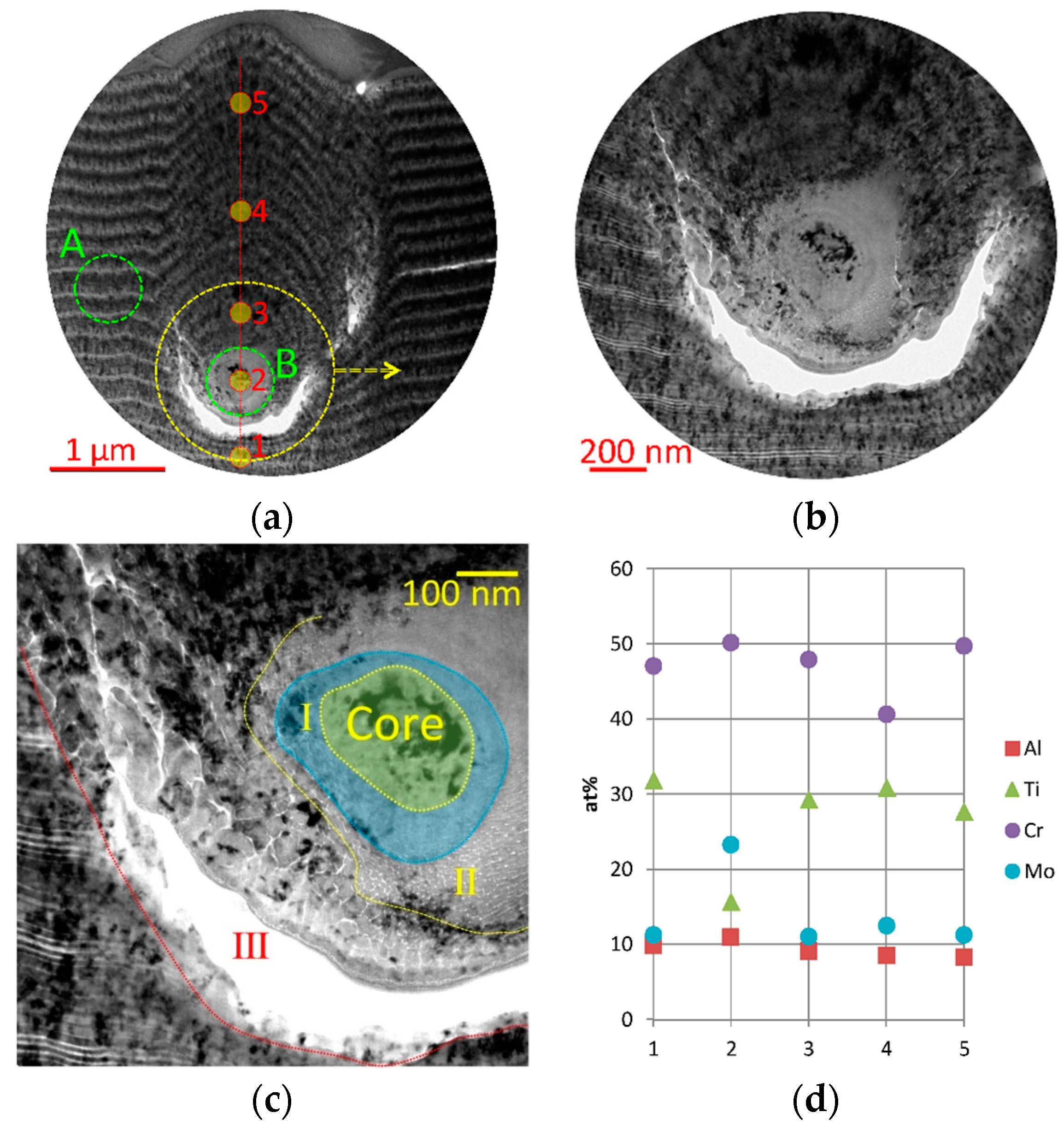
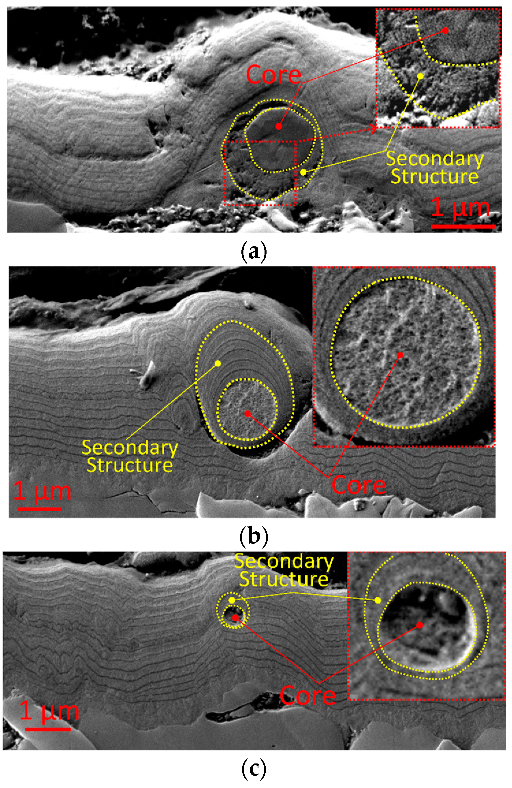
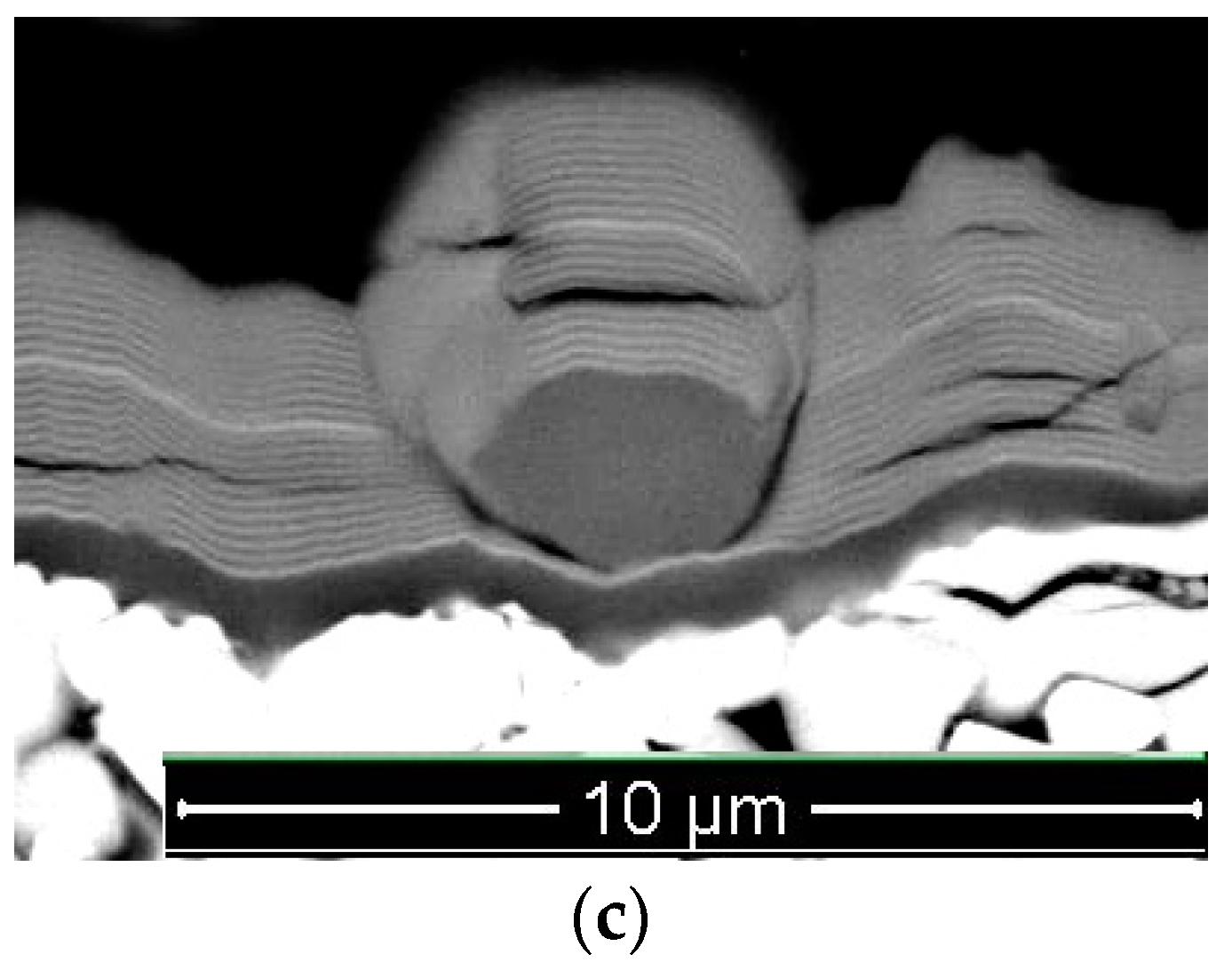
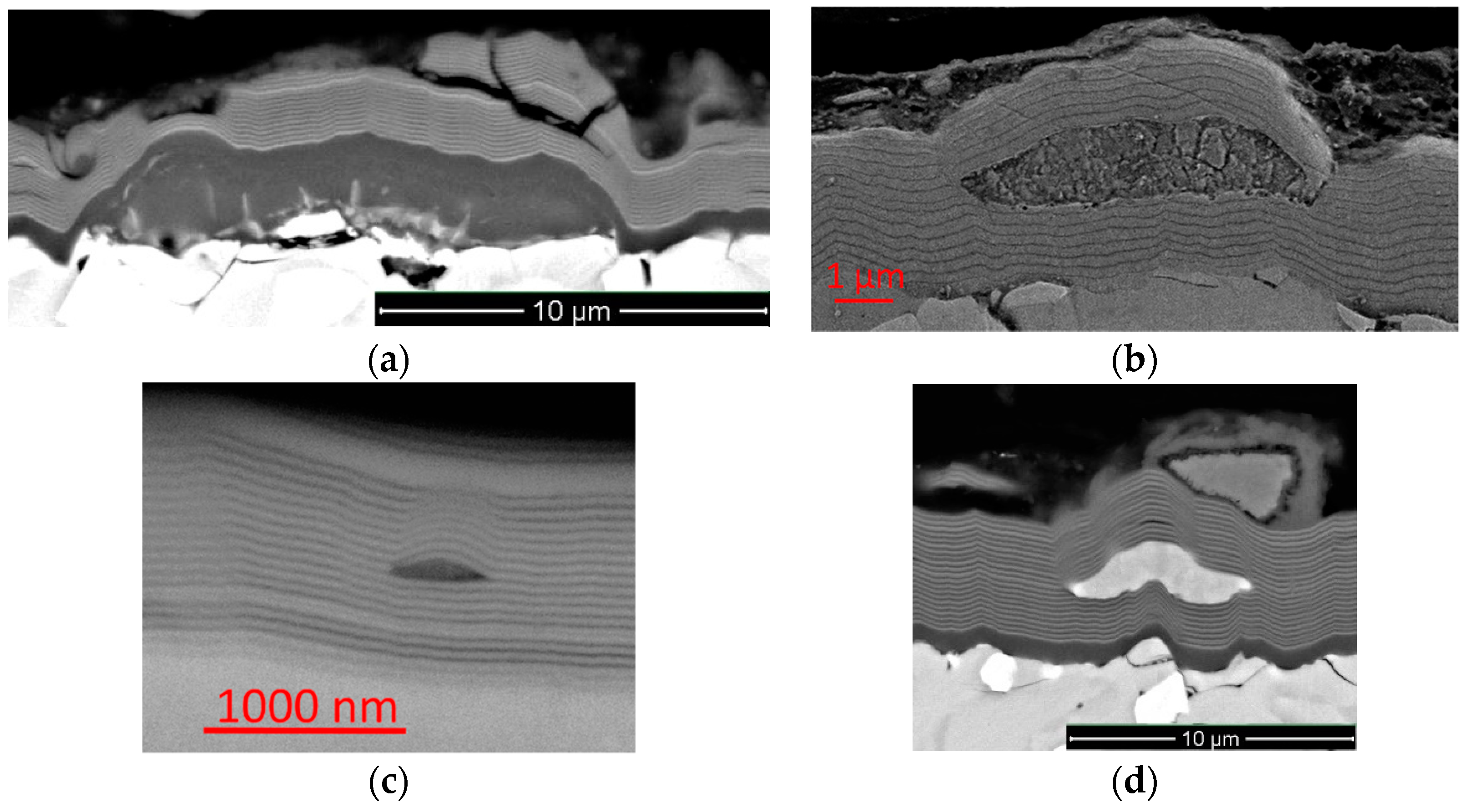
  • In the shape of a sphere with a secondary multilayered structure formed around the microdroplet core, and the sizes of such microdroplet cores are within the range of 100–1000 nm. The formation of such microdroplets can also be associated with the high thermal conductivity of the metals forming them;
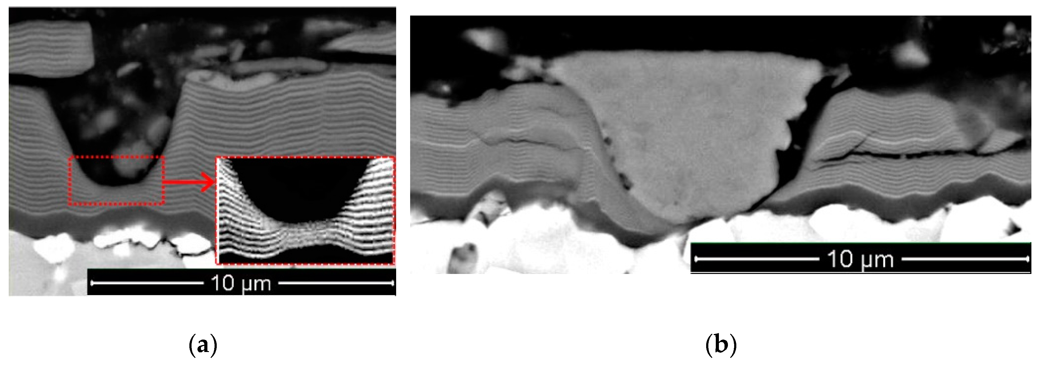
  • In the shape of an ellipse or a tear, when a secondary structure is not typical, and the microdroplet sizes usually stay within 3–5 µm;
  • In the shape of a lens, without a surrounding secondary structure, with either large (7–10 µm) or smaller sizes. The formation of such microdroplets can also be associated with the high thermal conductivity of the metals forming them, as well as the formation of nitride compounds that are more refractory compared to pure metal. Due to the above, the surface of the microdroplet solidifies when the microdroplet moves from the cathode to the deposition surface.
While penetrating into a coating, a microdroplet noticeably distorts its nanolayer structure. Such distortion occurs both due to the plastic deformation of nanolayers upon impact of the microdroplet and due to the effect of the microdroplet on the structure of nanolayers deposited after its penetration.
The shape of a microdroplet and the presence or absence of secondary structures, surrounding the microdroplet core, relates both to its size (and, accordingly, weight) and to the conditions affecting the process of the movement of the microdroplet in the unit chamber (the influence of multidirectional plasma flows and magnetic fields). It can be assumed that the movement of some microdroplets with the diameter of 100–1000 nm from the source to the deposition surface can be significantly slowed down (up to tens and even hundreds of seconds) under the influence of multidirectional plasma flows and magnetic fields.
Based on the study focused on the shape of a microdroplet core and the specific features typical for the formation of the secondary structure around it, a hypothesis has been proposed, according to which for some microdroplets, it takes much more time than previously assumed for the movement from a cathode to the deposition surface.
Comprehensive mathematical modeling of the processes under consideration is necessary for a detailed study of the causes and mechanisms typical for the formation of microdroplets of different shapes, as well as the mechanisms of the formation of secondary structures on their surface.

Author Contributions

Conceptualization, A.V. and S.G.; methodology, S.G. and A.V.; formal analysis, F.M., C.S., and I.S.; investigation, A.V., F.M., N.S., J.B., N.A., and I.S.; resources, S.G.; data curation, A.V. and J.B.; writing—original draft preparation, A.V.; writing—review and editing, A.V.; project administration, A.V. and S.G.; funding acquisition, S.G. All authors have read and agreed to the published version of the manuscript.

Funding

This research was funded by Ministry of Science and Higher Education of the Russian Federation, Grant No. 0707-2020-0025.

Conflicts of Interest

The authors declare no conflict of interest.

References

  1. Boxman, R.; Goldsmith, S. Macroparticle contamination in cathodic arc coatings: Generation, transport and control. Surf. Coat. Technol. 1992, 52, 39–50. [Google Scholar] [CrossRef]
  2. Steffens, H.-D.; Mack, M.; Moehwald, K.; Reichel, K. Reduction of droplet emission in random arc technology. Surf. Coat. Technol. 1991, 46, 65–74. [Google Scholar] [CrossRef]
  3. Akari, K.; Tamagaki, H.; Kumakiri, T.; Tsuji, K.; Koh, E.; Tai, C. Reduction in macroparticles during the deposition of TiN films prepared by arc ion plating. Surf. Coat. Technol. 1990, 1990, 312–323. [Google Scholar] [CrossRef]
  4. Sanders, D.M. Ion beam self-sputtering using a cathodic arc ion source. J. Vac. Sci. Technol. A 1988, 6, 1929–1933. [Google Scholar] [CrossRef]
  5. Vereshchaka, A.A.; Mgaloblishvili, O.; Morgan, M.; Batako, A.D.L. Nano-scale multilayered-composite coatings for the cutting tools. Int. J. Adv. Manuf. Technol. 2014, 72, 303–317. [Google Scholar] [CrossRef]
  6. Michalski, A. Structure and properties of coatings composed of TiN–Ti obtained by the reactive pulse plasma method. J. Mater. Sci. Lett. 1984, 3, 505–508. [Google Scholar] [CrossRef]
  7. Aksenov, I.I.; Bren’, V.G.; Osipov, V.A.; Padalka, V.G.; Khoroshikh, V.M. Plasma in a stationary vacuum-arc discharge. I. Plasma flux formation. High Temp. 1983, 21, 160–164. [Google Scholar]
  8. Metel, A.; Bolbukov, V.; Volosova, M.; Grigoriev, S.; Melnik, Y. Equipment for deposition of thin metallic films bombarded by fast argon atoms. Instrum. Exp. Tech. 2014, 57, 345–351. [Google Scholar] [CrossRef]
  9. Sobol’, O.V.; Andreev, A.A.; Grigoriev, S.N.; Stolbovoy, V.A. See more physical characteristics, structure and stress state of vacuum-arc tin coating, deposition on the substrate when applying high-voltage pulse during the deposition. Probl. At. Sci. Technol. 2011, 4, 174–177. [Google Scholar]
  10. Metel, A.S.; Grigoriev, S.N.; Melnik, Y.A.; Bolbukov, V.P. Broad beam sources of fast molecules with segmented cold cathodes and emissive grids. Instrum. Exp. Tech. 2012, 55, 122–130. [Google Scholar] [CrossRef]
  11. Metel, A.S.; Bolbukov, V.P.; Volosova, M.A.; Grigoriev, S.N.; Melnik, Y.A. Source of metal atoms and fast gas molecules for coating deposition on complex shaped dielectric products. Surf. Coat. Technol. 2013, 225, 34–39. [Google Scholar] [CrossRef]
  12. Metel, A.S.; Melnik, Y.; Metel, A. Broad fast neutral molecule beam sources for industrial-scale beam-assisted deposition. Surf. Coat. Technol. 2002, 156, 44–49. [Google Scholar] [CrossRef]
  13. Miernik, K.; Walkowicz, J. Spatial distribution of microdroplets generated in the cathode spots of vacuum arcs. Surf. Coat. Technol. 2000, 125, 161–166. [Google Scholar] [CrossRef]
  14. Anders, S.; Anders, A.; Yu, K.M.; Yao, X.; Brown, I. On the macroparticle flux from vacuum arc cathode spots. IEEE Trans. Plasma Sci. 1993, 21, 440–446. [Google Scholar] [CrossRef]
  15. Baouchi, A.W.; Perry, A.J. A study of the macroparticle distribution in cathodic-arc-evaporated TiN films. Surf. Coat. Technol. 1991, 41, 253–257. [Google Scholar] [CrossRef]
  16. Utsumi, T.; English, J.H. Study of electrode products emitted by vacuum arcs in form of molten metal particles. J. Appl. Phys. 1975, 46, 126. [Google Scholar] [CrossRef]
  17. Vyskočil, J.; Musil, J. Arc evaporation of hard coatings: Process and film properties. Surf. Coat. Technol. 1990, 43–44, 299–311. [Google Scholar] [CrossRef]
  18. Devia, A.; Benavides, V.; Restrepo, E.; Arias, D.; Ospina, R. Influence substrate temperature on structural properties of TiN/TiC bilayers produced by pulsed arc techniques. Vacuum 2006, 81, 378–384. [Google Scholar] [CrossRef]
  19. Zhao, Z.; Poulikakos, D.; Fukai, J. Heat transfer and fluid dynamics during the collision of a liquid droplet on a substrate: I—Modeling. Int. J. Heat Mass Transf. 1996, 39, 2771–2789. [Google Scholar] [CrossRef]
  20. Fukai, J.; Zhao, Z.; Poulikakos, D.; Megaridis, C.M.; Miyatake, O. Modeling of the deformation of a liquid droplet impinging upon a flat surface. Phys. Fluids A 1993, 5, 2588–2599. [Google Scholar] [CrossRef]
  21. Waldvogel, J.M.; Poulikakos, D.; Wallace, D.B.; Marušák, R. Transport phenomena in picoliter size solder droplet dispension. J. Heat Transf. 1996, 118, 148–156. [Google Scholar] [CrossRef]
  22. Waldvogel, J.; Poulikakos, D. Solidification phenomena in picoliter size solder droplet deposition on a composite substrate. Int. J. Heat Mass Transf. 1997, 40, 295–309. [Google Scholar] [CrossRef]
  23. Liu, W.; Wang, G.X.; Matthys, E.F. Determination of the thermal contact coefficient for a molten droplet impinging on a substrate. Transp. Phenom Mater. Process. Manuf. ASME HTD 1992, 196, 111–118. [Google Scholar]
  24. Attinger, D.; Haferl, S.; Zhao, Z.; Poulikakos, D. Transport phenomena in the impact of a molten droplet on a surface: Macroscopic phenomenology and microscopic considerations. Part II: Heat transferand solidification. Ann. Rev. Heat Transf. 2000, 11, 65–143. [Google Scholar]
  25. Bennett, T.; Poulikakos, D. Heat transfer aspects of splat-quench solidification: Modelling and experiment. J. Mater. Sci. 1994, 29, 2025–2039. [Google Scholar] [CrossRef]
  26. Pasandideh-Fard, M.; Mostaghimi, J. On the spreading and solidification of molten particles in a plasma spray process effect of thermal contact resistance. Plasma Chem. Plasma Process. 1995, 16, S83–S98. [Google Scholar] [CrossRef]
  27. Xiong, B.; Megaridis, C.M.; Poulikakos, D.; Hoang, H. An investigation of key factors affecting solder microdroplet deposition. J. Heat Transf. 1998, 120, 259–270. [Google Scholar] [CrossRef]
  28. Attinger, D.; Poulikakos, D. On quantifying interfacial thermal and surface energy during molten microdroplet surface deposition. J. Atom. Spray 2003, 13, 309–319. [Google Scholar] [CrossRef]
  29. Bhardwaj, R.; Longtin, J.P.; Attinger, D. A numerical investigation on the influence of liquid properties and interfacial heat transfer during microdroplet deposition onto a glass substrate. Int. J. Heat Mass Transf. 2007, 50, 2912–2923. [Google Scholar] [CrossRef] [Green Version]
  30. Kumar, A.; Gu, S. Modelling impingement of hollow metal droplets onto a flat surface International. Int. J. Heat Fluid Flow 2012, 37, 189–195. [Google Scholar] [CrossRef]
  31. Du, J.; Wei, Z.; Wu, H.; Zhao, G.; Wang, X. Numerical simulation of pileup process in metal microdroplet deposition manufacture. J. Enhanc. Heat Transf. 2016, 23, 413–430. [Google Scholar] [CrossRef]
  32. Muboyadzhyan, S.A.; Budinovskii, S.A.; Gorlov, D.S.; Doronin, O.N. Structure and microporosity of ion-plasma condensed coatings deposited from a two-phase vacuum-arc discharge plasma flow containing evaporated material microdroplets. Russ. Met. 2019, 2019, 52–62. [Google Scholar] [CrossRef]
  33. Kashkarov, E.B.; Nikitenkov, N.; Syrtanov, M.S.; Sutygina, A.N.; Gvozdyakov, D.V. Effect of bias potential on the structure and distribution of elements in titanium-nitride coatings obtained by cathodic-arc deposition. J. Surf. Investig. 2016, 10, 648–651. [Google Scholar] [CrossRef]
  34. Anders, A. Cathodic Arcs; Springer Science Business Media, LLC: New York, NY, USA, 2008. [Google Scholar] [CrossRef]
  35. Zhang, S.; Dong, L.; Dong, L.; Gu, H.; Wan, R. Influence of sputtering power on the structure and mechanical properties of Zr–Nb–N nanocomposite coatings prepared by multi-target magnetron Co-sputtering. Key Eng. Mater. 2013, 537, 307–310. [Google Scholar] [CrossRef]
  36. Klostermann, H.; Fietzke, F.; Labitzke, R.; Modes, T.; Zywitzki, O. Zr–Nb–N hard coatings deposited by high power pulsed sputtering using different pulse modes. Surf. Coat. Technol. 2009, 204, 1076–1080. [Google Scholar] [CrossRef]
  37. Blinkov, I.V.; Volkhonskii, A.O. The effect of deposition parameters of multilayered nanostructure Ti–Al–N/Zr–Nb–N/Cr–N coatings obtained by the arc-PVD method on their structure and composition. Russ. J. Non-Ferrous Met. 2012, 53, 163–168. [Google Scholar] [CrossRef]
  38. Makino, Y.; Saito, K.; Murakami, Y.; Asami, K. Phase change of Zr–Al–N and Nb–Al–N films prepared by magnetron sputtering method. Solid State Phenom. 2007, 127, 195–200. [Google Scholar] [CrossRef]
  39. Yang, G.; Etchessahar, E.; Bars, J.; Portier, R.; Debuigne, J. A miscibility gap in the FCC δ-nitride region of the ternary system titanium-zirconium-nitrogen. Scr. Met. Mater. 1994, 31, 903–908. [Google Scholar] [CrossRef]
  40. Duwez, P.; Odell, F. Phase Relationships in the Binary Systems of Nitrides and Carbides of Zirconium, Columbium, Titanium, and Vanadium. J. Electrochem. Soc. 1950, 97, 299. [Google Scholar] [CrossRef]
  41. Sridar, S.; Kumar, R.; Kumar, K.H. Thermodynamic modelling of Ti–Zr–N system. Calphad 2017, 56, 102–107. [Google Scholar] [CrossRef]
  42. Wang, D.-Y.; Chang, C.-L.; Hsu, C.-H.; Lin, H.-N. Synthesis of (Ti,Zr)N hard coatings by unbalanced magnetron sputtering. Surf. Coat. Technol. 2000, 130, 64–68. [Google Scholar] [CrossRef]
  43. Uglov, V.V.; Anishchik, V.M.; Zlotski, S.V.; Abadias, G.; Dub, S. Structural and mechanical stability upon annealing of arc-deposited Ti–Zr–N coatings. Surf. Coat. Technol. 2008, 202, 2394–2398. [Google Scholar] [CrossRef]
  44. Kuo, Y.-L.; Lee, C.; Lin, J.-C.; Yen, Y.-W.; Lee, W.-H. Evaluation of the thermal stability of reactively sputtered (Ti,Zr)Nx nano-thin films as diffusion barriers between Cu and Silicon. Thin Solid Films 2005, 484, 265–271. [Google Scholar] [CrossRef]
  45. Tonghe, Z.; Yuguang, W.; Zhiyong, Z.; Zhiwei, D. The ternary Ti (Zr, N) phases formation and modification of TiN coatings by Zr+ MEVVA ion implantation. Surf. Coat. Technol. 2000, 131, 326–329. [Google Scholar] [CrossRef]
  46. Niu, E.; Li, L.; Lv, G.; Chen, H.; Li, X.; Yang, X.; Yang, S. Characterization of Ti–Zr–N films deposited by cathodic vacuum arc with different substrate bias. Appl. Surf. Sci. 2008, 254, 3909–3914. [Google Scholar] [CrossRef]
  47. Uglov, V.V.; Anishchik, V.M.; Khodasevich, V.V.; Prikhodko, Z.L.; Zlotski, S.V.; Abadias, G.; Dub, S.N. Structural characterization and mechanical properties of Ti–Zr–N coatings, deposited by vacuum arc. Surf. Coat. Technol. 2004, 180–181, 519–525. [Google Scholar] [CrossRef]
  48. Regent, F.; Musil, J. Magnetron sputtered Cr–Ni–N and Ti–Mo–N films: Comparison of mechanical properties. Surf. Coat. Technol. 2001, 142–144, 146–151. [Google Scholar] [CrossRef]
  49. Kuleshov, A.; Uglov, V.V.; Chayevski, V.V.; Anishchik, V.M. Properties of coatings based on Cr, Ti, and Mo nitrides with embedded metals deposited on cutting tools. J. Frict. Wear 2011, 32, 192–198. [Google Scholar] [CrossRef]
  50. Hangwei, C.; Yuan, G.; Lin, Y.; Zhikang, M.; Chenglei, W. High-temperature oxidation behavior of (Ti,Cr)N coating deposited on 4Cr13 stainless steel by multi-arc ion plating. Rare Met. Mater. Eng. 2014, 43, 1084–1087. [Google Scholar] [CrossRef]
  51. Panjan, P.; Navinsek, B.; Cvelbar, A.; Zalar, A.; Milosev, I. Oxidation of TiN, ZrN, TiZrN, CrN, TiCrN and TiN/CrN multilayer hard coatings reactively sputtered at low temperature. Thin Solid Films 1996, 281, 298–301. [Google Scholar] [CrossRef]
  52. Caplan, D.; Cohen, M. The volatilization of chromium oxide. J. Electrochem. Soc. 1961, 108, 438. [Google Scholar] [CrossRef]
  53. Kim, K.H.; Choi, E.Y.; Hong, S.G.; Park, B.G.; Yoon, J.H.; Yong, J.H. Syntheses and mechanical properties of Cr–Mo–N coatings by a hybrid coating system. Surf. Coat. Technol. 2006, 207, 4068–4072. [Google Scholar] [CrossRef]
  54. Qi, D.; Lei, H.; Wang, T.; Pei, Z.; Gong, J.; Sun, C. Mechanical, microstructural and tribological properties of reactive magnetron sputtered Cr–Mo–N films. J. Mater. Sci. Technol. 2015, 31, 55–64. [Google Scholar] [CrossRef]
  55. Koshy, R.A.; Graham, M.E.; Marks, L.D. Temperature activated self-lubrication in CrN/Mo2N nanolayer coatings. Surf. Coat. Technol. 2010, 204, 1359–1365. [Google Scholar] [CrossRef]
  56. Liu, W.; Li, A.; Wu, H.; He, R.; Huang, J.; Long, Y.; Deng, X.; Wang, Q.; Wang, C.; Wu, S. Effects of bias voltage on microstructure, mechanical properties, and wear mechanism of novel quaternary (Ti, Al, Zr)N coating on the surface of silicon nitride ceramic cutting tool. Ceram. Int. 2016, 42, 17693–17697. [Google Scholar] [CrossRef]
  57. Liu, W.; Li, A.; Wu, H.; Long, Y.; Huang, J.; Deng, X.; Wang, C.; Wang, Q.; Wu, S. Effects of gas pressure on microstructure and performance of (Ti, Al, Zr)N coatings produced by physical vapor deposition. Ceram. Int. 2016, 42, 17436–17441. [Google Scholar] [CrossRef]
  58. Sergevnin, V.S.; Blinkov, I.V.; Belov, D.; Volkhonskii, A.O.; Skryleva, E.A.; Chernogor, A.V. Phase formation in the Ti–Al–Mo–N system during the growth of adaptive wear-resistant coatings by arc PVD. Inorg. Mater. 2016, 52, 735–742. [Google Scholar] [CrossRef]
  59. Tomaszewski, Ł.; Gulbiński, W.; Urbanowicz, A.; Suszko, T.; Lewandowski, A.; Gulbiński, W. TiAlN based wear resistant coatings modified by molybdenum addition. Vacuum 2015, 121, 223–229. [Google Scholar] [CrossRef]
  60. Yang, K.; Xian, G.; Zhao, H.; Fan, H.; Wang, J.; Wang, H.; Du, H. Effect of Mo content on the structure and mechanical properties of TiAlMoN films deposited on WC–Co cemented carbide substrate by magnetron sputtering. Int. J. Refract. Met. Hard Mater. 2015, 52, 29–35. [Google Scholar] [CrossRef]
  61. Sergevnin, V.S.; Anikin, V.N.; Volkhonskii, A.; Belov, D.; Kuznetsov, D.; Gorshenkov, M.; Skryleva, E. Wear behaviour of wear-resistant adaptive nano-multilayered Ti–Al–Mo–N coatings. Appl. Surf. Sci. 2016, 388, 13–23. [Google Scholar] [CrossRef]
  62. Grigoriev, S.; Vereschaka, A.; Milovich, F.; Tabakov, V.; Sitnikov, N.; Andreev, N.; Sviridova, T.; Bublikov, J. Investigation of multicomponent nanolayer coatings based on nitrides of Cr, Mo, Zr, Nb, and Al. Surf. Coat. Technol. 2020, 401, 126258. [Google Scholar] [CrossRef]
  63. Vereschaka, A.A. Development of assisted filtered cathodic vacuum arc deposition of nano-dispersed multi-layered composite coatings on cutting tools. Key Eng. Mater. 2013, 581, 62–67. [Google Scholar] [CrossRef]
  64. Vereschaka, A.A.; Grigoriev, S.N.; Sitnikov, N.N.; Oganyan, G.V.; Batako, A. Working efficiency of cutting tools with multilayer nano-structured Ti–TiCN–(Ti,Al)CN and Ti–TiCN–(Ti,Al,Cr)CN coatings: Analysis of cutting properties, wear mechanism and diffusion processes. Surf. Coat. Technol. 2017, 332, 198–213. [Google Scholar] [CrossRef]
  65. Grigoriev, S.N.; Sobol, O.V.; Beresnev, V.M.; Serdyuk, I.V.; Pogrebnyak, A.D.; Kolesnikov, D.A.; Nemchenko, U.S. Tribological characteristics of (TiZrHfVNbTa)N coatings applied using the vacuum arc deposition method. J. Frict. Wear 2014, 35, 359–364. [Google Scholar] [CrossRef]
  66. Vereschaka, A.; Tabakov, V.; Grigoriev, S.; Aksenenko, A.; Sitnikov, N.; Oganyan, G.; Seleznev, A.; Shevchenko, S. Effect of adhesion and the wear-resistant layer thickness ratio on mechanical and performance properties of ZrN–(Zr,Al,Si)N coatings. Surf. Coat. Technol. 2019, 357, 218–234. [Google Scholar] [CrossRef]
  67. Vereschaka, A.; Tabakov, V.; Grigoriev, S.; Sitnikov, N.; Milovich, F.; Andreev, N.; Sotova, C.; Kutina, N. Investigation of the influence of the thickness of nanolayers in wear-resistant layers of Ti–TiN–(Ti,Cr,Al)N coating on destruction in the cutting and wear of carbide cutting tools. Surf. Coat. Technol. 2020, 385, 125402. [Google Scholar] [CrossRef]
  68. Vereschaka, A.; Aksenenko, A.; Sitnikov, N.; Migranov, M.; Shevchenko, S.; Sotova, C.; Batako, A.D.L.; Andreev, N. Effect of adhesion and tribological properties of modified composite nano-structured multi-layer nitride coatings on WC–Co tools life. Tribol. Int. 2018, 128, 313–327. [Google Scholar] [CrossRef]
  69. Vereschaka, A. Improvement of working efficiency of cutting tools by modifying its surface properties by application of wear-resistant complexes. Adv. Mater. Res. 2013, 712, 347–351. [Google Scholar] [CrossRef]
  70. Volosova, M.A.; Grigor’ev, S.N.; Kuzin, V.V. Effect of titanium nitride coating on stress structural inhomogeneity in oxide-carbide ceramic. Part 4. Action of heat flow. Refract. Ind. Ceram. 2015, 56, 91–96. [Google Scholar] [CrossRef]
  71. Kuzin, V.V.; Grigor’ev, S.N.; Volosova, M.A. Effect of a TiC coating on the stress-strain state of a plate of a high-density nitride ceramic under nonsteady thermoelastic conditions. Refract. Ind. Ceram. 2014, 54, 376–380. [Google Scholar] [CrossRef]
  72. Kuzin, V.; Grigoriev, S.N.; Fedorov, M.Y. Role of the thermal factor in the wear mechanism of ceramic tools. Part 2: Microlevel. J. Frict. Wear 2015, 36, 40–44. [Google Scholar] [CrossRef]
  73. Vereschaka, A.A.; Grigoriev, S.N.; Volosova, M.A.; Batako, A.; Vereschaka, A.S.; Sitnikov, N.; Seleznev, A. Nano-scale multi-layered coatings for improved efficiency of ceramic cutting tools. Int. J. Adv. Manuf. Technol. 2016, 90, 27–43. [Google Scholar] [CrossRef]
  74. Vereschaka, A.; Tabakov, V.; Grigoriev, S.; Sitnikov, N.; Oganyan, G.; Andreev, N.; Milovich, F. Investigation of wear dynamics for cutting tools with multilayer composite nanostructured coatings in turning constructional steel. Wear 2019, 420–421, 17–37. [Google Scholar] [CrossRef]
  75. Vereschaka, A.; Grigoriev, S.; Sitnikov, N.; Milovich, F.; Aksenenko, A.; Andreev, N. Investigation of performance and cutting properties of carbide tool with nanostructured multilayer Zr–ZrN–(Zr0.5,Cr0.3,Al0.2)N coating. Int. J. Adv. Manuf. Technol. 2019, 102, 2953–2965. [Google Scholar] [CrossRef]
  76. Vereschaka, A.S.; Grigoriev, S.N.; Tabakov, V.P.; Sotova, E.S.; Vereschaka, A.A.; Kulikov, M.Y. Improving the efficiency of the cutting tool made of ceramic when machining hardened steel by applying nano-dispersed multi-layered coatings. Key Eng. Mater. 2014, 581, 68–73. [Google Scholar] [CrossRef]
  77. Engineering ToolBox. Thermal Conductivity of Metals, Metallic Elements and Alloys. 2005. Available online: https://www.engineeringtoolbox.com/thermal-conductivity-metals-d_858.html (accessed on 1 November 2020).
Figure 1. (ac) structure and (d) chemical composition of the microdroplet in the Ti–TiN–(Ti,Cr,Mo,Al)N coating (TEM), selected area electron diffraction (SAED) pattern for area A (e) and area B (f). The microdroplet core is surrounded by area I (crystal sizes are 3–5 nm), then by area II (crystal sizes are 8–15 nm), and then by area III (crystal sizes are 20–40 nm).
Coatings 10 01204 g001aCoatings 10 01204 g001b
Figure 2. (a) the microdroplet of Cr–Mo, embedded into the structure of the Ti–TiN–(Ti,Cr,Mo,Al)N coating, (b,c) the microdroplets of Nb–Zr, embedded into the structure of the Ti–TiN–(Ti,Al,Nb,Zr)N coating (SEM 2).
Coatings 10 01204 g002
Figure 3. Examples of the influence of microdroplets on the structure of the (a,b) Ti–TiN–(Ti,Cr,Mo,Al)N and (c) Ti–TiN–(Ti,Nb,Zr,Al)N coatings (SEM 1).
Coatings 10 01204 g003aCoatings 10 01204 g003b
Figure 4. Examples of the influence of microdroplets on the structure of (a) Ti–TiN–(Ti,Cr,Mo,Al)N and (b) Ti–TiN–(Ti,Nb,Zr,Al)N coatings (SEM 1).
Coatings 10 01204 g004
Figure 5. Examples of the influence of microdroplets on the structure of (a,b) Ti–TiN–(Ti,Nb,Zr,Al)N and (c,d) Ti–TiN–(Ti,Cr,Mo,Al)N coatings (a,c,d—SEM 1,b—SEM 2).
Coatings 10 01204 g005
Table 1. Parameters of stages of the technological process of the deposition of coatings.
ProcesspN (Pa)U (V)ITi (A)IAl (A)IZr–Nb (A)ICr–Mo (A)
Pumping and heating of vacuum chamber0.06+207512065
Heating and cleaning of products with gaseous plasma2.0100 DC/900 AC
f = 10 kHz, 2:1
8580
Deposition of coating0.42−800 DC751605573
Cooling of products0.06
Note: ITi = current of titanium cathode, IZr–Nb = current of Zr–Nb cathode, IAl = current of Al cathode, ICr–Mo = current of Cr–Mo cathode, pN = gas pressure in chamber, U = voltage on substrate. Table rotation frequency n = 0.7 rpm.
Table 2. Coefficients of thermal conductivity of metals depending on temperature, W⁄(m × K) [77].
Chemical Element127 °C527 °C727 °C
Al24022090
Ti20.419.720.7
Cr87.371.365.3
Mo134118112
Nb55.261.364.4
Zr21.621.623.7
Table 3. Values of the interplanar spacings d (for the first six HKL indices) for nitrides, forming the Ti–TiN–(Ti,Cr,Mo,Al)N coating.
PhaseCrNMo2N(Cr,Mo)NTiNHKL
Space Group Fm 3 ¯ m Fm 3 ¯ m Fm 3 ¯ m Fm 3 ¯ m
12.390 Å2.408 Å2.42 Å2.448 Å(111)
22.070 Å2.085 Å2.09 Å2.120 Å(002)
31.464 Å1.475 Å1.48 Å1.499 Å(202)
41.248 Å1.257 Å1.26 Å1.278 Å(113)
51.195 Å1.204 Å1.20 Å1.224 Å(222)
61.035 Å1.043 Å1.04 Å1.060 Å(004)
Publisher’s Note: MDPI stays neutral with regard to jurisdictional claims in published maps and institutional affiliations.

