Article

Understanding the Influence of High Velocity Thermal Spray Techniques on the Properties of Different Anti-Wear WC-Based Coatings

by
Andrea Garfias Bulnes
,
Vicente Albaladejo Fuentes
,
Irene Garcia Cano
* and
Sergi Dosta
Thermal Spray Centre, CPT, Departament CMiQF, Universitat de Barcelona, 08028 Barcelona, Spain
*
Author to whom correspondence should be addressed.
Coatings 2020, 10(12), 1157; https://doi.org/10.3390/coatings10121157
Submission received: 15 October 2020 / Revised: 20 November 2020 / Accepted: 24 November 2020 / Published: 26 November 2020
(This article belongs to the Special Issue Surface Modification of Metals and Alloys)

Abstract

:
This work analyzes the differences found in hard metal coatings produced by two high velocity thermal spray techniques, namely high velocity oxy-fuel (HVOF) and high velocity air-fuel (HVAF). Additionally, the effect of the metallic matrix and ceramic composition and the original carbide grain size on coating properties is compared to the most studied standard reference material sprayed by HVOF, WC-Co. For this evaluation, the physical properties of the coatings, including feedstock characteristics, porosity, thickness, roughness, hardness, and phase composition were investigated. Several characterization methods were used for this purpose: optical microscopy (OM), scanning electronic microscopy (SEM), Energy-dispersive X-ray spectroscopy (EDS), and X-ray Diffraction (XRD), among others. The final performance (abrasive wear and corrosion resistance) shown by the coatings obtained by these two methodologies was also analyzed. Thus, the abrasive wear resistance was analyzed by the rubber-wheel test, while the corrosion resistance was characterized with electrochemical methods. The characterization results obtained clearly showed that the coatings exhibit different microstructures according to feedstock powder characteristics (carbide grain size and/or composition) and the thermal spray process used for its deposition. Thus, the incorporation of WB to the cermet composition led to a high hardness coating, and the complementary hardness and toughness of the WC-Co coatings justify its better abrasion resistance. The presence of Ni on the metal matrix increases the free corrosion potential of the coating to more noble region. However, the WC-Co coatings show a lower corrosion rate and hence a higher protective performance than the rest of the coatings.

1. Introduction

In recent years, the technological demands of industry have exceeded the performance of traditional coatings. Therefore, new coatings that are capable of fulfilling these needs have attracted important attention.
One example of these materials are cemented carbides, which are commonly known as hard metals and represent a group of hard and resistant compounds. They are a mixture of metallic and ceramic particles that combine the hardness and resistance of carbides (WC, TiC, TaC) with the toughness and plasticity of a metallic binder (Co, Ni, Cr). The properties of the hard metal coatings depend mainly on its composition and on the physical characteristics of its raw materials, hence any variation in these two parameters represents a change in the final microstructure, making it possible to obtain final specific tailored properties for particular applications [1].
Specifically, tungsten carbides (WC) are commercially one of the most successful metallurgic products in industry because of their combination of physical, chemical, and mechanical properties, which make them useful for applications in cutting tools and machinery exposed to wear [2]. In this respect, different WC-based hard metals can be found on the market showing different properties according to the diverse metallic binder and metal/ceramic compositions, as mentioned above.
Among the different WC-based cermets, WC-Co (with cobalt percentage ranging from 5 wt.% to 25 wt.%) coatings remain the most studied materials for industrial applications. Because of the great cohesion between the tungsten carbide grains and the cobalt metallic binder, these are composite materials with a great hardness–toughness relation, which makes them one of the best wear resistant materials. Tungsten carbides with cobalt have excellent mechanical properties. However their poor corrosion resistance restricts the number of applications in which they may be used, especially in the chemical industry [3,4,5].
As an alternative, the cobalt metallic binder can be substituted by nickel and/or nickel alloys in order to enhance its anticorrosive and thermal crack resistance properties. Since cobalt is expensive and its accessibility is complicated, the use of nickel (WC-Ni-based) lowers the costs and facilitates the supplies [2]. With the partial or complete substitution of cobalt with nickel, a considerable improvement in resistance to corrosion while maintaining anti-wear properties is to be expected [2,6,7,8].
Another alternative for the improvement of the hard metal performance is the addition of tungsten boride to the matrix. The WB grains are hard ceramic particles that will likely improve the hardness of the coatings. It has been shown that the WB incorporation enhances the mechanical properties of the substrate, since it has a high thermal shock resistance, high conductivity, and high corrosion and wear resistance [9,10,11].
During the production processes of hard metals, the WC suffer decarburization and oxidation, reacting to form di-tungsten carbide (W2C), metallic tungsten (W) and oxy carbides. These reactions are inconvenient for the enhancement of the mechanical properties of the coatings, thus the subproducts formation must be reduced by controlling the process conditions. It has been found that the addition of chromium (WC-Co–Cr) somehow modifies the decomposition of the WC grains, preventing decarburization, while improving the matrix binding [12,13,14,15,16].
The final coating properties depend not only on its composition, but also on its lamellar microstructure. The formation of this lamellar microstructure depends on three main factors: the feedstock characteristics (material, size and morphology), the process method and parameters, and the substrate [17].
The feedstock material characteristics depend on their manufacturing process. Other than chemical composition, important factors are the size distribution, morphology, porosity bulk density, and grain size of the particles. Understanding the characteristics of the powder is crucial for the interpretation of the properties of the coating. Denser feedstock particles lead to coatings with better mechanical properties [17].
On the other hand, one method to deposit these types of materials in the form of coatings is by thermal spraying (TS). In general terms, in TS, the material feedstock is heated up in the form of powder using a hot gas stream until the melting or semi-melting of the particles. Then, they are accelerated to high velocities towards a substrate, leading to the adhesion of the semi-molten particles to the surface. From the TS technology arise several techniques, driven by combustion or electric discharge. Flame thermal spray, high velocity oxygen/air fuel (HVOF/HVAF), and detonation spraying (D-Gun) are based on combustion, while wire arc and plasma are based on electrical energy [18].
Among all the TS processes, HVOF/HVAF (high velocity oxygen/air fuel) are the most extended for obtaining coatings made of cemented carbides [19]. In these two processes (HVOF and HVAF), a mixture of gases is introduced into a combustion chamber. Inside this chamber, a spark generates a combustion reaction that heats the flowing gases to high temperatures. As the gases exit the chamber, powder particles are injected either axially or radially into the hot gases stream. This new outlet stream (heated mixture of gases and powder particles) flows into a De Laval type nozzle with a convergent-divergent structure that drastically reduces the flow area, leading to a considerable increase in the mixture flow velocity. As the gas velocity is increased at the outlet of the nozzle, the powder particles are ejected at supersonic speeds until they collide with a substrate and produce a coating [20].
The general equipment arrangement of the HVOF and HVAF processes is the same, however some important differences, summarized in Table 1, are to be noted regarding the operation conditions. In the case of HVOF, the gas mixture that is introduced into the combustion chamber consists of a fuel species (either hydrogen, propylene, methane, propane or heptane), nitrogen (inert gas) and oxygen (oxidizing component). In contrast, in the HVAF process, the oxygen of the gas mixture is replaced by dry air. This difference in the gas mixture composition has an impact on the flame temperature during the spraying process. HVOF jets show higher temperatures, in the range of 2700 and 3100 °C depending on the stoichiometry of the mixture, whilst HVAF operates at lower temperatures between 1900 and 2000 °C due to the higher ratio of N2 (inert component) in the gas flow.
The lower ratio of fuel/oxygen used in HVAF compared to HVOF, allows to introduce a higher total gas amount into the combustion chamber. Consequently, the gas flow inside the nozzle is choked, leading to an increase in pressure inside the equipment. When the pressured gas-particle mixture flows and expands through the convergent-divergent nozzle, this pressure decreases as the velocity increases continuously. Commonly, HVOF operates at pressures up to 1 MPa, that induce particle velocities from 600 to 750 m/s, whereas the HVAF spraying process can reach up to 2 MPa, leading to particle velocities in the range of 600–840 m/s [18].
An efficient way to control the flame temperature and the velocity of the particles is by decreasing the fuel/oxygen ratio of the gases, and by increasing the flow rate inside the chamber through the injection of inert components (such as N2). The control of these two variables is important, because at higher temperatures and lower particle velocities (which is the case of the HVOF process), the powder particles are more susceptible to undergo decarburization, resulting in undesired phases such as W2C and W [6]. In the case of HVAF, the powders do not suffer significant decarburization or oxidation, as they are subjected to lower temperatures and exit the equipment at higher velocities [21].
The final properties of the coatings not only depend on the TS process used, but on the feedstock material characteristics too. The chemical composition, particle size distribution, morphology, porosity bulk density, and grain size of the particles are important features that should be taken into account when spraying WC-based powders. Thus, understanding the characteristics of the powder is crucial for the interpretation of the properties of the coating. Denser feedstock particles lead to coatings with better mechanical properties [17].
Because of this dependence of the coatings properties on both the feedstock characteristics and thermal spray processes, comparative studies have gained a lot of interest over the last years. This work analyzes two different thermal spray methods for the production of hard metals, namely HVOF and HVAF, by comparing the most studied standard reference material, WC-Co, sprayed by HVOF, with (a) WC-cermet coatings with different metallic matrix/ceramic composition and (b) WC-cermet coatings with different carbide sizes. This comparison comprises a study of the physical properties that constitute the microstructure of the coatings (feedstock characteristics, porosity, thickness, roughness, hardness, and phase composition) and mechanical properties (wear and corrosion resistance).

2. Materials and Methods

2.1. Feedstock Powders

The sprayed coatings were made with six different commercial powders. A WC-Co powder (AMPERIT 518.074, Goslar, Germany) was selected as reference material for obtaining HVOF and HVAF coatings.
To reveal the effect of the metallic matrix and ceramic compositions, three other materials with micrometric WC-grain size were sprayed: WC-Co–Cr, WC-NiMoCrFeCo, and WC-WB-CoCr with the powders AMPERIT 556.074, AMPERIT-529.074, and AMPERIT-539.074, respectively.
The relevance of feedstock powder carbide grain size in the final coating performances was evaluated using two other coatings with nanometric WC-grain size were sprayed: WC-Co with the powder FUJIMI W555-20/5 (Kakamigahara, Japan) and WC-Co–Cr with FUJIMI W928-32/10.
Table 2 shows the commercial names of the powders along with their coating identification names for this work, in which the suffix -m is included in the label for powders produced by AMPERIT (micrometric WC grain size) or -n for powders produced by FUJIMI (nanometric WC grain size).

2.2. Thermal Spraying Conditions

All powders were sprayed on flat low carbon steel substrates (100 mm × 20 mm × 5 mm) and cylindrical low carbon steel substrates (φ = 25.4 mm × h = 25.4 mm), previously grit blasted with alumina. All blasted substrates had a mean roughness (Ra) greater or equal than 4μm.
All the coatings prepared by HVOF and HVAF methods were deposited in 15 layers sprayed at a 500 mm/s rate and at a distance of 250 mm, except for powders WC-Ni and WC-WB in the HVOF process which were sprayed at a distance of 300 mm. For the HVOF procedure was used a DJH 2600 gun (found in CPT facilities, Sultzer Metco, Pfäffikon, Switzerland) with a gas flow of hydrogen, oxygen, and air of 635, 267, and 344 L/min, respectively.

2.3. Powder and Coating Characterization

The size of the particles of the powders was analyzed in duplicate with a laser diffraction particle sizing analyzer LS 13 320 Model Dry Powder System (Beckman Coulter Inc., Indianapolis, IN, USA).
The metallographic preparation of the coatings was made according to the standards ASTM E1920-03(2014) [22]. Cross-sectional surface characteristics and the thickness of the coatings were analyzed with the optical microscope Leica DMI500M (Wetzlar, Germany) according to the standard ASTM E3-11(2017) [23].
Roughness was analyzed with 10 measures per coating with the profilometer SJ-210 Mitutoyo (Aurora, IL, USA). The mean porosity value was obtained from 30 measures with the software ImageJ (Version: 1.50i) from images at 20× magnification taken with the optical microscope according to standard ASTM E2109-01(2014) [24].
A Phenom ProX Desktop SEM (Waltham, MA, USA) was used in order to compare the superficial characteristics of the transversal side of the coatings and the feedstock powders. Elemental microanalysis of the composition of the samples was carried out with the equipment Quantax EDS Bruker Nano (Billerica, MA, USA) integrated to a SEM JEOL5310 (Akishima, Japan).
In order to analyze the phases and crystal structure of the coatings, the XRD equipment PANalytical X’Pert PRO MPD (PANalytical, Almelo, The Netherlands)was used with a radiation of Cu Kα (λ = 1.5418 Å) from 5 until 100° 2θ with a 0.017° step, measuring 100 s per step.
Vickers hardness and toughness were assessed according to the standard ASTM E384-17 [25] and following the work described by Lima, et al. [26], respectively. For each coating, 10 indentations were made with a force of 0.3 and 1 kgF respectively, with Matzuzawa MTZ-alfa equipment.
The adhesion of the coating to the steel substrate was measured with equipment SERVOSIS MCH-102ME (Madrid, Spain) according to the standard ASTM C633-13 [27]. Three samples of each coating were adhered to a non-sprayed counterpart with the adhesive HTK Ultrabond 100 (Hamburg, German). A tensile test was performed at a rate of 0.01 mm/s until cohesive, adhesive, or glue failure.
For the wear resistance to abrasion analysis, the Rubber Wheel method was tested with the tailored equipment CM4 OL-2000 (CM4, Cervelló, Barcelona, Spain) according to the standard ASTM G65-16e1 [28]. The test was performed at a velocity of 139 rpm, with a force of 50 N, a 22.6 cm diameter wheel, and Ottawa silica sand as the abrasive agent.
The corrosion resistance of the coatings was characterized with electrochemical experiments in 80 mL solution of NaCl 3.5%. The polarization curve was tested using the equipment VSP (Biologic Science Instruments Seyssinet-Pariset, Auvergne-Rhone-Alpes, France) at normal conditions in a potential range of 100 to +350 mV with respect to open circuit potential (Eopc) over 1 cm2 sample surface. The corrosion potential (Ecorr) and corrosion current (Icorr) were calculated with the software EC-Lab (V10.44). Ecorr was obtained from a Tafel Fit extrapolation, while Icorr was calculated according to the Stern–Geary Equation (1).
I corr = β a · β c ( 2.3 · ( β a   +   β c ) ) R p
where βa and βc are the anodic and cathodic currents, respectively, and Rp is the polarization resistance.

3. Results and Discussion

3.1. Powder Characterization

In thermal spraying technology, it is accepted that the microstructure of the coatings depends considerably on the characteristics of the powder particles at the point of collision with the substrate. In the HVOF/HVAF processes, the residence time of the particles inside the equipment, although minimal due to the high velocities (which depend on the gases flow rate) of the outlet flow of the gases, controls the heat transfer between the hot gases and the feedstock material and consequently determines its temperature at the point of impact with the substrate. At this point, the microstructure of the coating is influenced by the processes of deformation and solidification, caused by the high velocities and temperatures of the particles. These two factors are highly dependent on the size distribution of the powder particles, which is typically polydisperse. As a result, the particles of different sizes experience different momentum and thermal inertias, affecting the physical states of the particles during flight time and impact with the substrate [29,30]. Therefore, it is important to study the size distribution of the feedstock and adjust the process parameters accordingly. Hence, the characteristics and size distribution of the powders played an important role in the coatings microstructure, especially in terms of porosity and roughness.
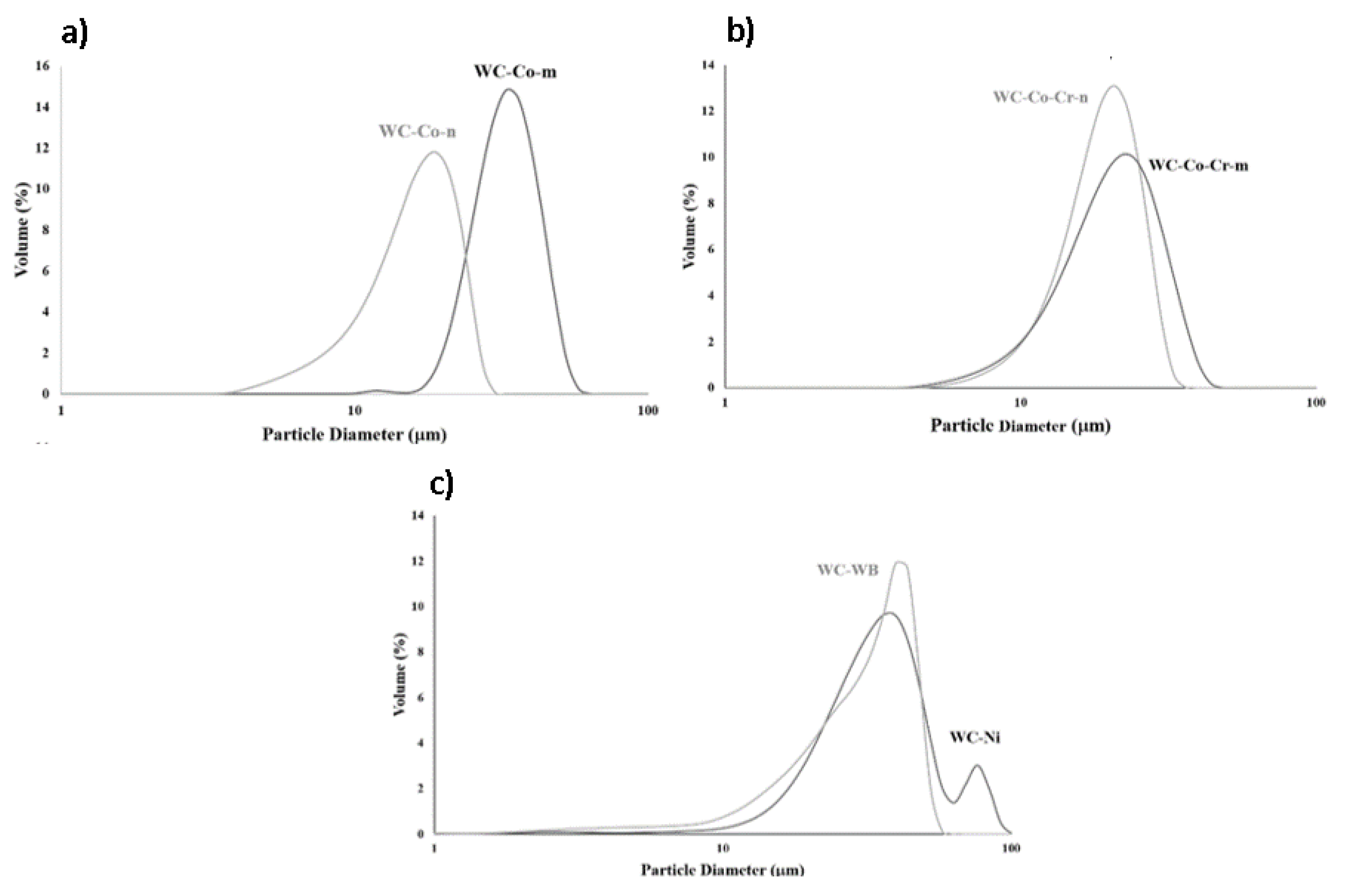
The statistical size distribution of the particles and the size distribution curves for all the powders under study in this work are reported in Table 3 and Figure 1, respectively. This comparison shows that the powders mainly resulted to have a homogeneous distribution, as expected for commercial feedstock materials. Nonetheless, some differences can be found regarding powder properties depending on the feedstock material composition. Thus, WC-Co (micro and nanometric) revealed a relevant difference in their mean particle size of these powders, which shows as the particles of the WC-Co-m powder are larger than that of the WC-Co-n material. In addition, the nanometric powder showed a narrower size distribution than the micrometric one. No relevant differences were observed between powders WC-Co–Cr-m and WC-Co–Cr-n, which resulted in almost equivalent distributions with similar mean particle size values, as it can be seen in Figure 1b. On the contrary, the powders WC-WB and WC-Ni presented heterogeneous distributions, where the former one showed a distorted distribution with a bump, and the last one a distribution with two groups of particles with different sizes, resulting in the highest mean size distribution of all powders, with 80% of the particles with a diameter of between 20 and 61 µm.
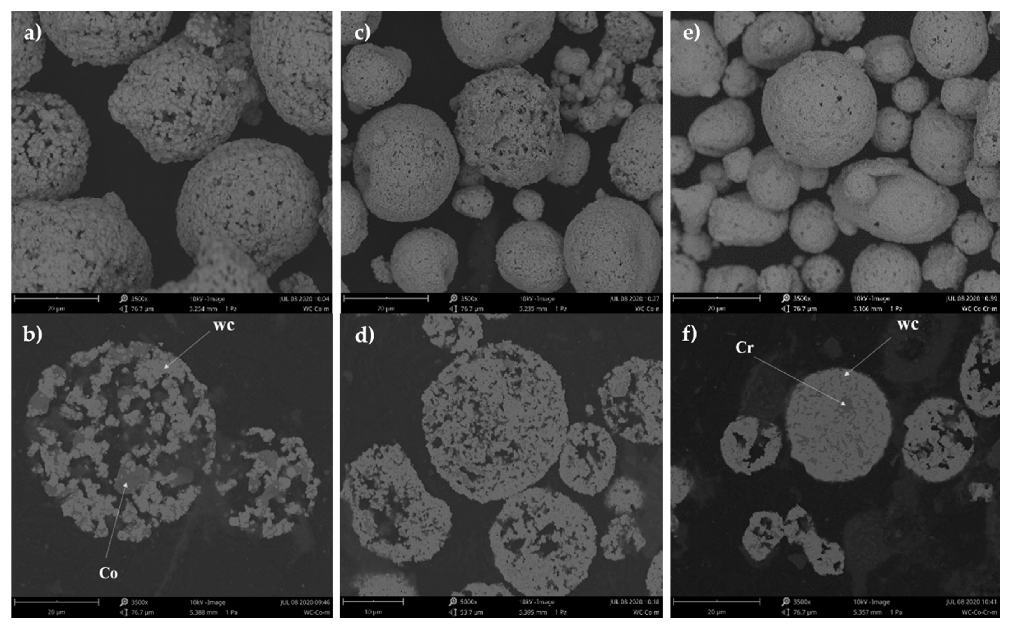
The spherical or irregular morphology of the powders and their microstructure was inspected by SEM. Figure 2 shows only the images recorded for the most representative powders (WC-Co-m, WC-Co-n, and WC-Co–Cr-m) for the sake of brevity. SEM images confirmed that all powders were composed of agglomerated particles and had a spherical morphology and were composed of WC grains embedded in a metallic binder: Co, Co–Cr (for WC-Co–Cr and WC-WB-Co–Cr powders), or NiMoCrFeCo, depending on the composition of the powder. Consistent with the particle size distribution results (Table 3), the free surface images showed the different sized particles of the powders. For instance, it is particularly interesting to observed the size diversity in the WC-Co-n powder (Figure 2c).
In contrast to the free surface images, that show the size difference of the agglomerated particles between all powders, in the cross-sectional images, the microstructure of the WC-based particles can be observed and analyzed [31]. Thus, the evaluation of the surface and core porosity level of the powders revealed that the WC-Co-m were slightly more porous than the WC-Co-n and WC-Co–Cr-n feedstock materials. Even though they are not shown, WC-Co–Cr-m powder presented similar porosity as WC-Co-m whilst powders WC-WB and WC-Ni were highly porous.
In order to identify the elements present in the powder composition, an EDS mapping analysis of the particles was performed and the images of this analysis are shown in Supplementary Figures S1–S3 of the supplementary information file of this manuscript. The results allow conclude that the dark regions of the particles microstructure (shown in Figure 2b,f) corresponded to the metallic binder of each powder, while the bright regions were ascribed to WC and/or WB grains. In this respect, in the powders with composition WC-Co, it was clearly identified that the metal matrix contained pure Co. Additionally, comparing their microstructure, in Figure 2b,d is confirmed that the powders labelled as micrometric showed higher size of the WC grains compared to the ones labelled as nanometric. Finally, in the case of the powders WC-Co–Cr and WC-WB, Cr predominated in the composition of the dark regions. In the same way, powder WC-Ni was mainly composed of Cr, Ni, and Mo.
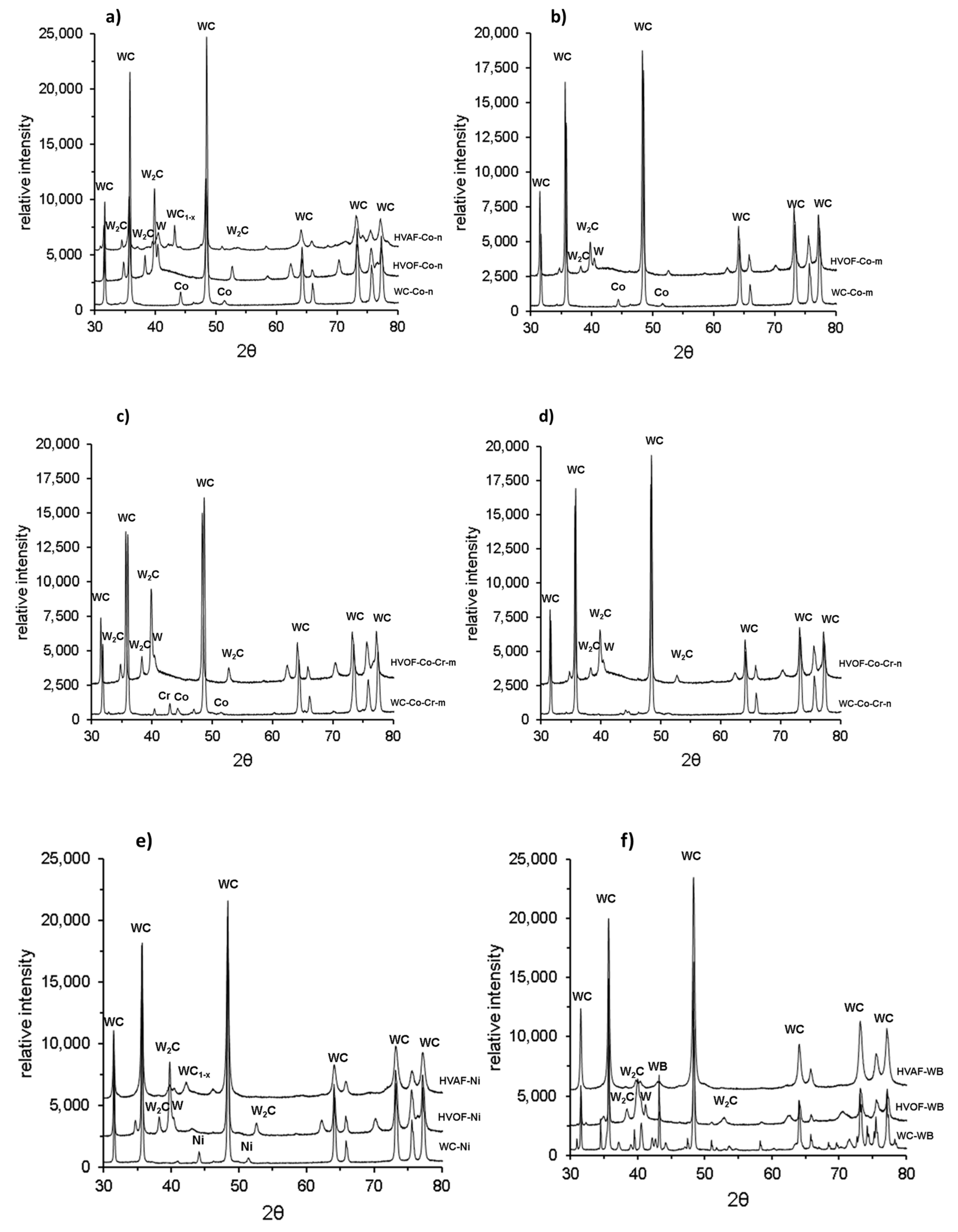
For corroborating the presence of these phases, the XRD diffractograms of the powders are shown in Figure 3 According to the patterns, all the powders were found to contain only WC as a ceramic component and pure phases (Co, Cr, Ni, Mo) as the metallic binder.
In summary, the comparative analysis of the powders characteristics allowed concluding that all the powders are composed of WC grains embedded in a metallic matrix formed by metallic pure phases. WC-Co-m and WC-Co–Cr-m are composed of larger particles showing higher porosity than their respective nanometric powders. In addition, WC-Ni and WC-WB powders showed a broad size distribution, with two peaks in the WC-Ni case. These powders showed a highly porous microstructure.

3.2. Microstructure of the TS Coatings

It is worth remembering that the objective of this work was to compare the final coatings properties regarding the thermal spray process and composition and particle characteristics of feedstock materials. For this reason, the same spraying parameters were used in HVOF and HVAF processes respectively, for all the powders, except for powders WC-Ni and WC-WB, which were sprayed at a higher distance in order to minimize high porosity values.
As expected, the coatings exhibited different microstructures according to their grain size, composition and thermal spray process used. Figure 4 shows representative polished cross-sectional recorded by optical microscopy (OM) (left) and SEM (right) images of the coatings, while Table 4 shows their thickness, porosity, roughness, and hardness values.
In general, from the results included in Table 4, it can be concluded that the coatings sprayed by HVAF were thicker, less porous and more homogeneous than the HVOF ones. Thus, the coatings sprayed by HVAF showed thickness values between 230 and 150 µm, against values between 133 and 113 µm. With the exception of the coating HVAF-WB, with a porosity value higher than 9%, all coatings had low porosity with values between <1% and 2%. In the case of the roughness of the coatings, it may be suggested that this is influenced by the cermet composition. In this respect, WC-Co coatings showed a smother surface than WC-Ni and WC-WB coatings. No clear differences are observed in the roughness values measured for the same coating compositions but obtained by HVOF or HVAF, with the exception of the coating HVAF-WB which presented a mean roughness Ra of 8.2 ± 0.6 µm, while the other HVOF coating presented Ra value of 5.3 ± 0.4 µm.
These data were found to be consistent with the porosity observed in the free surface and cross-sectional SEM images of the powders, as the powder used for preparing this coating also showed a high porosity. However, the coating porosity is not only dependent on the powders characteristics, but also on the final particle temperature during spraying process. When particles are heated up to higher temperatures, it is easier for them to melt on-flight before colliding with the substrate, resulting in denser coatings. Thus, despite the fact that WC-Co-m, WC-Co–Cr-m, and WC-Ni powders were very porous materials, the high density shown by their respective coatings allow for the conclusion that the spraying parameters used were aggressive enough for melting the particles.
Cross section images show that the particles that build up the coatings are strongly bonded to each other, since no cracks nor delamination areas were observed. Furthermore, the SEM images at high magnifications made it possible to observe the different phases in the microstructure of the coatings. All of them showed a homogenous distribution of the WC grains embedded into a darker metallic matrix along with some pores that might have been formed between particle splats. In Figure 4a,b the differences in the microstructure are clearly shown, especially regarding the WC grain size between micrometric and nanometric coatings. The WC grain size proved to be in the range of 1–4 µm for micrometric powders WC-Co-m and WC-Co–Cr-m, and 300–500 nm for nanometric powders WC-Co-n and WC-Co–Cr-n. Likewise powders WC-Ni and WC-WB had WC grains with sizes between <1–3 µm and <1–5 µm, respectively.
Looking at the coatings microstructure, it can be observed that those sprayed by HVOF showed some distinguished regions (darker than the WC grains), which might be attributed either to the metallic matrix or to the presence of undesired phases, difficultly distinguished in HVAF coatings. It is widely accepted that, in the thermal spraying methodology, the phase composition of a coating (WC-grains, metallic matrix and undesired phases) strongly depends on the flame temperature achieved. In this respect, the HVOF process leads to hotter and more oxidizing flame conditions than HVAF technique, which may explain these differences. In order to better identify these regions, the powders and coatings were further analyzed by EDS (Supplementary Figures S4–S6). This analysis confirmed the regions ascribed to the WC grains, W2C, and metallic matrix, as indicated in the labels of Figure 4a,c. The identification of W2C (lighter continuous regions surrounding WC grains with rounded shaped) allows concluding that certain processes of dissolution and decarburization of the WC grains occurred during spraying procedure. At high HVOF flame temperatures, the mechanism of decarburization starts with the melting of the metallic binder, since it has a lower melting point than the WC carbides. Afterwards, the WC grains begin to dissolve in the molten metal and, at the gas-liquid interface, carbon is released by its reaction with the oxygen of the gases. At the point of impact with the substrate, the particles are rapidly quenched and the dissolved WC grains become supersaturated, resulting in the formation of W2C [32]. In contrast, the W2C phase was not clearly observed in the microstructure of the HVAF coatings.
A microstructure comparison between HVOF and HVAF coatings can be observed in Figure 4c,d. In these images, it is shown that in the microstructure of the coating HVOF-Ni has a high presence of these lighter regions between different sized rounded grains, whereas coating HVAF-Ni only showed irregular grains embedded in the metallic matrix.
The XRD patterns of all the coatings were recorded for further support of the conclusion drawn from the visual inspection (Figure 3). As expected, all the coatings were composed mainly of the phases also identified in their respective powders, that is, WC as ceramic phase and their correspondent metallic pure phases as matrix. In agreement with previous results, HVAF coatings showed little or none undesired phases, while some HVOF coatings suffered relevant decarburization. Thus, in the case of the HVOF coatings patterns, the presence of W2C and W phases indicated that decarburization occurred. As above mentioned, since the HVOF process operates at higher temperatures, the coatings sprayed by this method were more likely to form undesired phases. This is clearly observed in coatings HVOF-Co-n and HVOF-Co–Cr-n, as they were the ones that showed more content of W2C and W. Among all the HVOF coatings, the HVOF-Co-m was the one that underwent less decarburization, since the sprayed conditions (used for all coatings) were the optimal ones for the size distribution of this conventional powder. For this reason, the nanostructured coating HVOF-Co-n showed more W2C phases in comparison to the HVOF-Co-m one, which can be understood regarding the smaller WC grain size for the nanometric powder that facilitates the dissolution of WC original grains and their final decarburization during fast solidification. Another factor that affected the presence of the undesired phases is the binder composition. As mentioned before, the addition of Cr to the matrix is known to prevent the WC grains decarburization. This explains that the XRD patterns of both coatings HVOF-Co–Cr-n and HVOF-Co–Cr-m feature few differences between them in terms of W2C presence and, for hence, it points out that less decarburization occurs than for the coating HVOF-Co-n. Coatings HVOF-Ni and HVOF-WB showed little decarburization, attributed to their composition and elevated mean particle size, as these bigger particles lightly experienced the elevated temperatures of the process.
Compared to HVOF methodology, during HVAF processes the powders are subjected to lower temperatures, therefore, except for the coating HVAF-Co-n which presented some W2C, WC1−x and W phases, most HVAF sprayed coatings showed practically no decarburization, meaning that the peaks corresponded in great part only to WC.
Finally, it is worth noting that the coatings HVOF-Co-n, HVOF-Co–Cr-m and HVOF-Co–Cr-n revealed one bump between 40°–45° indicating the presence of amorphous/nanochrystalline phases that were formed during the dissolution of the WC grains [15,33].
Thus, comparing the general microstructure of the coatings, it can be concluded that the ones sprayed by HVAF were thicker, less porous, and more homogeneous than the HVOF ones as they presented less roughness and practically no undesired phases due to the conservation of the WC grains during the TS process.

3.3. Mechanical and Anti-Wear Properties of the Coatings

The mechanical properties of the coatings are defined by its microstructure and composition. For instance, hardness values depend on several factors based on the microstructure of the coatings: (i) it increases as a function of cohesion between particles and coating porosity [34,35]; (ii) decarburization degree has an important impact on hardness since the higher amount of W2C, the higher the coating hardness [36]; (iii) it depends on the WC grain size, as a small carbide size leads to a high hardness [37]; and (iv) the presence of an amorphous/nanocrystalline phase results in an increased of cohesion between the carbide grain and the metallic matrix, that leads to an improvement of the hardness of the coating [9].
Taking into account the previous discussion about the coatings microstructure, it would be expected that HVOF coatings showed higher hardness than the HVAF coatings because of the presence of W2C in their composition. However, it becomes difficult to draw this conclusion looking at the Vickers hardness values (0.3 kgF) shown in Table 4. In general, these data revealed that all the coatings featured very high hardness, above 1500 HV0.3, independently of the TS process used for their preparation. This result suggests that the higher degree of amorphous/nanocrystalline phases identified in the HVAF coatings microstructure plays a key role and enhanced the cohesion between the carbide grains and the matrix, and as a result, increased the hardness of the coating.
Making a comparison based only on composition, both HVAF and HVOF coatings presented roughly the same trend in terms of hardness values. The coating with the WB in the ceramic phase resulted to have the greater hardness (this is not applicable for coating HVAF-WB since it showed very high porosity), which is followed, in order, by coatings with the binders Co–Cr, Co, and Ni-alloy. In the case of the micrometric and nanometric based coatings, the coating HVOF-Co-n resulted slightly harder than the conventional coating HVOF-Co-m, as the first one showed to have more W2C and phases than the former one. For this same reason, Co–Cr based coatings presented an inverse trend: the coating HVOF-Co–Cr-m resulted slighlty harder than the HVOF-Co–Cr-n.
Usually, high coating hardness is related to a decrease in its toughness, nonetheless hard metals have shown to maintain high toughness when having high hardness values [38]. This unique combination of properties makes them excellent materials for applications that require high resistance to wear. Toughness fracture resistance mainly depends on two factors in this kind of coating, namely the amount and characteristics of the binder phase present and the grain size of the carbide phase [39]. It is worth indicating that an attempt was made to measure the toughness of these coatings following the calculation method presented in the work of Lima et al. [22]. Nevertheless, it was not possible to obtain the toughness values since the maximum indentation force of the equipment was not strong enough to produce the adequate length of the cracks needed in order to fulfill one of the restrictions of the method. Despite the fact that the toughness was not analytically calculated, it may be suggested that all coatings presented very high fracture toughness due to the heavy load necessary for crack formation and propagation. In addition, this observation would point out that, in these HVOF and HVAF coatings, there exists a high cohesion strength among the splats forming the coating microstructure.
Another important property of hard metals is their adhesion with the substrate surface, which determines the actual utility of the coating. Nowadays, it is considered that coatings prepared by conventional TS techniques are mechanically anchored to the substrate. Thus, a perfectly controlled cleaning and grit blasting process of the substrate has a strong influence on the adhesion strength at the interface. However, the degree of fusion of the particles but also the interfacial bonding within the lamellar microstructure, which integrates the pores size and distribution [17] will be also crucial for a proper coating performance in terms of adhesion.
The adhesion strength of the coatings was measured by means of tensile tests and the results obtained are included in Table 4. In the case of the HVAF coatings, HVAF-Ni, HVAF-Co, and HVAF-WB failed by adhesion of the coating–substrate interface at 60.5 ± 8.0 MPa, 50.3 ± 6.0 MPa, and 48.2 ± 7.0 MPa values, respectively. This kind of failure indicated that, at these tensile strength values, the coating was not strong enough to maintain its bond with the substrate. Moreover, from the analysis of these values, it can be concluded that the metallic binder has a relevant role in the adhesion resistance of the coatings, since the HVAF coating showing the highest adhesion strength is that with the highest metal/ceramic ratio and also with the lowest melting point, HVAF-Ni.
On the contrary, all the HVOF coating were able to withstand a higher tensile force than that withstand by the adhesive, exceeding the 65 MPa. In such a case, this is consistent with the difference in flame temperature of both processes, and the high flame temperature reached in the HVOF process allows the particles to fuse together and leads to stronger bonds within the microstructure.
It is important to highlight that the high adhesion strength values reported for all the coatings is in agreement with previous analysis, and supports the suggestion that there is high cohesion between the particles in coating.
Rubber wheel experiments were performed for the HVAF sprayed coatings (HVAF-Co, HVAF-Ni, HVAF-WB), their respective HVOF coatings (HVOF-Co-n, HVOF-Ni, HVOF-WB), and the conventional coating (HVOF-Co-m) in order to evaluate their wear resistance to abrasive conditions. Wear behavior of the coatings during the experiments are shown in Figure 5. In this plot, it is observed, within the first minutes of the test, that the wear rate significantly dropped due to the rapid decrease of the roughness of the coatings. The ones that presented higher roughness values (HVAF-Ni and HVAF-WB) showed a steeper drop in the wear rate curve in comparison to HVAF-Co and the steel substrate. In general, after the point where the surface evened out, the wear rate followed a flatter behavior for all the coatings, indicating the hardening of the coatings and the substrate.
Abrasive wear is the main mechanism of wear when the surface of two materials are facing each other with the presence of a third body in between. Abrasion then causes the removal of particles from the softest material. It has been shown that the wear resistance of the hard metals coatings is highly dependent on its composition, carbide grain size, porosity, toughness and hardness values [39]. The degree of abrasive wear is defined by the hardness difference between the abrasive particles and the counter material, hence higher hardness values are desired to enhance the wear resistance of the coatings and ensure the protection of the coated surface. In the case of the cermets, both hardness and cohesion between the carbides are key properties to improve the abrasive wear resistance. It is clear that the WC particles contribute to the overall hardness, while the metallic matrix defines the cohesion of the WC grains. Therefore, it is important to consider the size of the carbide grains, the binder composition and the thermal sprayed conditions when analyzing the wear resistance of the coatings [39].
In Table 5 are shown the volume loss (measured at the end of the experiment) and the wear rate (final value in Figure 5 for each coating) calculated for all the TS coatings. As can be observed from these data, the coatings HVAF-Co-n and HVAF-Ni resulted to have higher resistance to wear than the other TS coatings with a similar volume loss. This result can be understood if it is considered that these coatings showed low roughness, the absence of undesired phases, and one of the highest thickness and hardness values of the analyzed coatings. HVAF-WB coating experienced a high volume loss value of 37.0 mm3, being even a greater value than the volume loss measured for the bare steel substrate, which can be explained because of its high porosity. For HVOF coatings, no clear differences in abrasive wear resistance were observed for the coatings HVOF-Co-m, HVOF-Co-n and HVOF-Ni as they showed practically identical wear rate values. In this case, HVOF-Co-n was expected to show the best performance (since nanostructured coatings are known to have enhanced mechanical properties), nevertheless this was not the case. As mentioned before, coating HVOF-Co-n suffered high decarburization, thus its abrasion resistance resulted degraded to slightly higher volume loss and wear rate values than coating HVOF-Co-m. In agreement with the results for HVAF technique, HVOF-WB coating also experienced a high volume loss, close to the value measure for the steel substrate (11.5 mm3 and 11.7 mm3, respectively). In this case, the HVOF-WB did not show a porosity that would explain the result, and for this reason, these volume loss and wear rates might be attributed to a poor cohesion between the WC/WB grains and the metallic matrix.
The corrosion behavior of the HVAF and HVOF coatings was evaluated and the resulting polarization curves are shown in Figure 6a,b. The actual values of Ecorr and Icorr inferred from the polarization curves and calculated with Equation (1), respectively, are shown in Table 5. According to this, a first differentiation can be made between coatings regarding the thermal spraying method used for its deposition, since, in general, the HVAF coatings show higher Ecorr and lower Icorr than the HVOF layers. This result can be clearly related to the differences found in the microstructure of coatings. It was demonstrated that HVAF coatings show higher compactness than HVOF coatings, that is a lower porosity and the presence of voids between splats, which is widely accepted in literature as a responsible of their better corrosion behavior [40].
When subjecting a coated material to corrosive conditions, it is expected for the coating to prevent the effects of corrosion and to ensure the correct operation of the substrate. In hard metals the Ecorr and Icorr values are intrinsic of the metallic matrix material. Taking into account the results shown in Figure 6, both HVOF and HVAF coatings can be classified as a function of their composition, from top to bottom, that is, from high to low Ecorr, as follows: Ni-based (HVOF-Ni & HVAF-Ni), Co-based (HVOF-Co & HVAF-Co) and WB-based (HVOF-WB & HVAF-WB). These data can be justified since Ni is a more noble metal than Co or Co–Cr alloys.
On the other hand, the comparison of the Icorr values between HVOF-Co & HVOF-Ni and HVAF-Co and HVAF-Ni shows that these coatings present similar corrosion rates under open circuit potentials. Despite of this, when the potential is shifted to the anodic region, these coatings clearly show a different behavior since HVOF-Co and HVAF-Co coatings show a lower current intensity value than the Ni-based coatings over a potential region approximately of −340 and −185 mV, respectively. This data suggests that under polarization conditions, the Co-based coatings will corrode more slowly than the Ni-based coatings. Considering that this kind of coating is supposed to act as a protective barrier between the environment and the substrate, this allows for the conclusion that the HVOF-Co and HVAF-Co coatings will show higher corrosion protective performance than the rest of the coatings studied.
Finally, low coating porosity is mandatory for good corrosion protection. In the case of the HVAF-WB coating, which showed very high porosity, it still shows a certain protective ability since its Ecorr is higher than that of the steel substrate. However, the high Icorr value measured for this material reveals that there is a severe rate of corrosion in this system which might be ascribed to steel corrosion, and hence it indicates that this is not a good protective coating.

4. Conclusions

The coatings exhibited different microstructures and mechanical properties according to their carbide size, composition, and the thermal spray process used. In general, all coatings showed a homogenous distribution of the WC grains embedded into a darker metallic matrix with strong cohesion between particles.
Different thermal spray methods, namely HVOF and HVAF, lead to coatings with different microstructures and mechanical properties. (a) Because of the higher flame temperature in HVOF, the coatings sprayed by this method were more likely to form undesired phases, resulting in the decarburization of the WC grains. (b) Due to the conservation of the WC grains during the TS process, HVAF coatings were thicker, less porous, and more homogeneous than the HVOF ones. (c) HVAF coatings were slightly more resistant to abrasive wear than HVOF coatings.
The metallic matrix, ceramic composition, and WC grain size were key factors in hardness and the mechanical properties of the coatings. (a) The coating with the WB matrix resulted to have the greater hardness, followed, in order, by coatings with the binders Co–Cr, Co, and Ni-alloy. (b) The WC-Co coating proved to be the one with higher resistance to abrasive wear and the one showing the higher corrosion protection to steel in NaCl media. (c) Coatings with a smaller grain lead to superior qualities of the coatings in terms of enhanced properties.

Supplementary Materials

The following are available online at https://www.mdpi.com/2079-6412/10/12/1157/s1, Figure S1: EDS mapping analysis of the WC-Co-m powder, (a) SEM image of the cross-section of the powder particle at 5000×, (b) Co-rich regions (blue) and (c) W-rich regions (red), Figure S2: EDS mapping analysis of the WC-Co-n powder, (a) SEM image of the cross-section of the powder particle at 5000×, (b) Co-rich regions (blue) and (c) W-rich regions (red), Figure S3: EDS mapping analysis of the WC-Co-Cr-n powder, (a) SEM image of the cross-section of the powder particle at 2000×, (b) Co-rich regions (blue), (c) W-rich regions (red) and (d) Cr-rich regions (yellow), Figure S4: EDS mapping analysis of the HVOF-Co-m coating, (a) SEM image of the cross-section of the coating at 5000×, (b) Co-rich regions (blue) and (c) W-rich regions (red), Figure S5: EDS mapping analysis of the HVOF-Co-n coating, (a) SEM image of the cross-section of the coating at 5000×, (b) Co-rich regions (blue) and (c) W-rich regions (red), Figure S6: EDS mapping analysis of the HVOF-Ni coating, (a) SEM image of the cross-section of the coating at 5000×, (b) Ni-rich regions (bright blue), (c) W-rich regions (red), (d) Cr-rich regions (yellow) and e) Mo-rich regions (pink).

Author Contributions

Conceptualization, A.G.B., V.A.F., I.G.C., and S.D.; methodology, A.G.B., V.A.F., and S.D.; software, A.G.B.; validation, A.G.B. and V.A.F.; formal analysis, A.G.B., V.A.F., I.G.C., and S.D.; investigation, A.G.B. and V.A.F.; writing—original draft preparation, A.G.B. and V.A.F.; writing—review and editing, I.G.C. and S.D.; supervision, I.G.C. and S.D.; project administration, V.A.F., I.G.C., and S.D.; funding acquisition, I.G.C. and S.D. All authors have read and agreed to the published version of the manuscript.

Funding

This research was funded by Programa Operatiu FEDER de Catalunya 2014–2020, Grant No. COMRDI16-1-0020.

Conflicts of Interest

The authors declare no conflict of interest.

References

  1. Lassner, E.; Schubert, W.-D. Tungsten; Springer: Boston, MA, USA, 1999; ISBN 978-1-4613-7225-7. [Google Scholar]
  2. Chang, S.H.; Chen, S.L. Characterization and properties of sintered WC-Co and WC-Ni-Fe hard metal alloys. J. Alloys Compd. 2014, 585, 407–413. [Google Scholar] [CrossRef]
  3. Stewart, D.A.; Shipway, P.H.; McCartney, D.G. Abrasive wear behaviour of conventional and nanocomposite HVOF-sprayed WC-Co coatings. Wear 1999, 225–229, 789–798. [Google Scholar] [CrossRef]
  4. Chivavibul, P.; Watanabe, M.; Kuroda, S.; Shinoda, K. Effects of carbide size and Co content on the microstructure and mechanical properties of HVOF-sprayed WC-Co coatings. Surf. Coat. Technol. 2007, 202, 509–521. [Google Scholar] [CrossRef]
  5. He, J.; Schoenung, J.M. A review on nanostructured WC-Co coatings. Surf. Coat. Technol. 2002, 157, 72–79. [Google Scholar] [CrossRef]
  6. Guilemany, J.M.; Sanchiz, I.; Mellor, B.G.; Llorca, N.; Miguel, J.R. Mechanical-property relationships of Co/WC and Co Ni Fe/WC hard metal alloys. Int. J. Refract. Met. Hard Mater. 1993, 12, 199–206. [Google Scholar] [CrossRef]
  7. Guilemany, J.M.; Nutting, J.; Miguel, J.R.; Dong, Z. Microstructure characterization of WC-Ni coatings obtained by HVOF thermal spraying. Scr. Met. Mater. 1995, 33, 55–61. [Google Scholar] [CrossRef]
  8. Testa, V.; Morelli, S.; Bolelli, G.; Benedetti, B.; Puddu, P.; Sassatelli, P.; Lusvarghi, L. Alternative metallic matrices for WC-based HVOF coatings. Surf. Coat. Technol. 2020, 402, 126308. [Google Scholar] [CrossRef]
  9. Bouaricha, S.; Legoux, J.-G.; Marple, B.R. HVOF Coatings Properties of the Newly Thermal Spray Composition WC-WB-Co. In Proceedings of the International Thermal Spray Conference 2005 (ITSC 2005), Basel, Switzerland, 2–4 May 2005; pp. 981–986. [Google Scholar]
  10. Brezinová, J.; Guzanová, A.; Draganovská, D.; Maruschak, P.O.; Landová, M. Study of selected properties of thermally sprayed coatings containing WC and WB hard particles. Acta Mech. Autom. 2016, 10, 296–299. [Google Scholar] [CrossRef] [Green Version]
  11. Brezinová, J.; Landová, M.; Guzanová, A.; Dulebová, L.; Draganovská, D. Microstructure, wear behavior and corrosion resistance of WC-FeCrAl and WC-WB-Co coatings. Metal 2018, 8, 399. [Google Scholar] [CrossRef] [Green Version]
  12. Murthy, J.K.N.; Rao, D.S.; Venkataraman, B. Effect of grinding on the erosion behaviour of a WC-Co-Cr coating deposited by HVOF and detonation gun spray processes. Wear 2001, 249, 592–600. [Google Scholar] [CrossRef]
  13. Perry, J.M.; Neville, A.; Hodgkiess, T. A comparison of the corrosion behavior of WC-Co-Cr and WC-Co HVOF thermally sprayed coatings by in situ Atomic Force Microscopy (AFM). J. Ther. Spray Technol. 2002, 11, 536–541. [Google Scholar] [CrossRef]
  14. Karimi, A.; Verdon, C.; Barbezat, G. Microstructure and hydroabrasive wear behaviour of high velocity oxy-fuel thermally sprayed WCCo(Cr) coatings. Surf. Coat. Technol. 1993, 57, 81–89. [Google Scholar] [CrossRef]
  15. Pulsford, J.; Kamnis, S.; Murray, J.; Bai, M.; Hussain, T. Effect of particle and carbide grain sizes on a HVOAF WC-Co-Cr coating for the future application on internal surfaces: Microstructure and wear. J. Ther. Spray Technol. 2018, 27, 207–219. [Google Scholar] [CrossRef] [Green Version]
  16. Wang, H.; Wang, X.; Song, X.; Liu, X.; Liu, X. Sliding wear behavior of nanostructured WC-Co-Cr coatings. Appl. Surf. Sci. 2015, 355, 453–460. [Google Scholar] [CrossRef]
  17. Ang, A.S.M.; Berndt, C.C. A review of testing methods for thermal spray coatings. Int. Mater. Rev. 2014, 59, 179–223. [Google Scholar] [CrossRef]
  18. Fauchais, P.L.; Heberlein, J.V.R.; Boulos, M.I. Thermal Spray Fundamentals; Springer: Boston, MA, USA, 2014; ISBN 978-0-387-28319-7. [Google Scholar]
  19. Fauchais, P.; Vardelle, A. Thermal Sprayed Coatings Used Against Corrosion and Corrosive Wear. In Advanced Plasma Spray Applications; IntechOpen: London, UK, 2012; pp. 3–39. ISBN 978-953-51-0349-3. [Google Scholar]
  20. Thorpe, M.L.; Richter, H.J. A pragmatic analysis and comparison of HVOF processes. J. Ther. Spray Technol. 1992, 1, 161–170. [Google Scholar] [CrossRef]
  21. Hulka, I.; Şerban, V.A.; Niemi, K.; Vuoristo, P.; Wolf, J. Comparison of structure and wear properties of fine-structured WC-CoCr coatings deposited by HVOF and HVAF spraying processes. Solid State Phenom. 2012, 188, 422–427. [Google Scholar] [CrossRef]
  22. ASTM E1920-03. Standard Guide for Metallographic Preparation of Thermal Sprayed Coatings; ASTM International: West Conshohocken, PA, USA, 2014. [Google Scholar]
  23. ASTM E3-11. Standard Guide for Preparation of Metallographic Specimens; ASTM International: West Conshohocken, PA, USA, 2017. [Google Scholar]
  24. ASTM E2109-01. Standard Test Methods for Determining Area Percentage Porosity in Thermal Sprayed Coatings; ASTM International: West Conshohocken, PA, USA, 2014. [Google Scholar]
  25. ASTM E384-17. Standard Test Method for Microindentation Hardness of Materials; ASTM International: West Conshohocken, PA, USA, 2017. [Google Scholar]
  26. Lima, M.M.; Godoy, C.; Avelar-Batista, J.C.; Modenesi, P.J. Toughness evaluation of HVOF WC-Co coatings using non-linear regression analysis. Mater. Sci. Eng. A 2003, 357, 337–345. [Google Scholar] [CrossRef]
  27. ASTM C633-13. Standard Test Method for Adhesion or Cohesion Strength of Thermal Spray Coatings; ASTM International: West Conshohocken, PA, USA, 2017. [Google Scholar]
  28. ASTM G65-16e1. Standard Test Method for Measuring Abrasion Using the Dry Sand/Rubber Wheel Apparatus; ASTM International: West Conshohocken, PA, USA, 2016. [Google Scholar]
  29. Li, M.; Christofides, P.D. Modeling and control of high-velocity oxygen-fuel (HVOF) thermal spray: A tutorial review. J. Ther. Spray Technol. 2009, 18, 753–768. [Google Scholar] [CrossRef] [Green Version]
  30. Li, M.; Christofides, P.D. Computational study of particle in-flight behavior in the HVOF thermal spray process. Chem. Eng. Sci. 2006, 61, 6540–6552. [Google Scholar] [CrossRef]
  31. Guilemany, J.M.; Dosta, S.; Miguel, J.R. The enhancement of the properties of WC-Co HVOF coatings through the use of nanostructured and microstructured feedstock powders. Surf. Coat. Technol. 2006, 201, 1180–1190. [Google Scholar] [CrossRef]
  32. Kear, B.; Skandan, G.; Sadangi, R. Factors controlling decarburization in HVOF sprayed nano-WC/Co hardcoatings. Scr. Mater. 2001, 44, 1703–1707. [Google Scholar] [CrossRef]
  33. Magnani, M.; Suegama, P.H.; Espallargas, N.; Dosta, S.; Fugivara, C.S.; Guilemany, J.M.; Benedetti, A.V. Influence of HVOF parameters on the corrosion and wear resistance of WC-Co coatings sprayed on AA7050 T7. Surf. Coat. Technol. 2008, 202, 4746–4757. [Google Scholar] [CrossRef]
  34. Celik, E.; Culha, O.; Uyulgan, B.; Ak Azem, N.F.; Ozdemir, I.; Turk, A. Assessment of microstructural and mechanical properties of HVOF sprayed WC-based cermet coatings for a roller cylinder. Surf. Coat. Technol. 2006, 200, 4320–4328. [Google Scholar] [CrossRef]
  35. Yang, Q.; Senda, T.; Ohmori, A. Effect of carbide grain size on microstructure and sliding wear behavior of HVOF-sprayed WC-12% Co coatings. Wear 2003, 254, 23–34. [Google Scholar] [CrossRef]
  36. Usmani, S.; Sampath, S.; Houck, D.L.; Lee, D. Effect of carbide grain size on the sliding and abrasive wear behavior of thermally sprayed WC-Co coatings. Tribol. Trans. 1997, 40, 470–478. [Google Scholar] [CrossRef]
  37. Ettmayer, P. Hardmetals and cermets. Annu. Rev. Mater. Sci. 1989, 19, 145–164. [Google Scholar] [CrossRef]
  38. Gahr, K.-H.Z. (Ed.) Chapter 2 Microstructure and Mechanical Properties of Materials. In Microstructure and Wear of Materials; Elsevier: Amsterdam, The Netherlands, 1987; Volume 10, pp. 8–47. ISBN 0167-8922. [Google Scholar]
  39. Liao, H.; Normand, B.; Coddet, C. Influence of coating microstructure on the abrasive wear resistance of WC/Co cermet coatings. Surf. Coat. Technol. 2000, 124, 235–242. [Google Scholar] [CrossRef]
  40. Liu, Y.; Liu, W.; Ma, Y.; Meng, S.; Liu, C.; Long, L.; Tang, S. A comparative study on wear and corrosion behaviour of HVOF- and HVAF-sprayed WC–10Co–4Cr coatings. Surf. Eng. 2017, 33, 63–71. [Google Scholar] [CrossRef]
Figure 1. Distribution size of the powders WC-Co-n and WC-Co-m (a), WC-Co–Cr-n and WC-Co–Cr-m and (b) WC-WB and WC-Ni (c).
Coatings 10 01157 g001
Figure 2. SEM images of the (a,b) WC-Co-m, (c,d) WC-Co-n and (e,f) WC-Co–Cr-m powders.
Coatings 10 01157 g002
Figure 3. XRD of the powders and HVOF/HVAF coatings obtained using: (a) WC-Co-n, (b) WC-Co-m, (c) WC-Co–Cr-m, (d) WC-Co–Cr-n, (e) WC-Ni and (f) WC-WB feedstock materials.
Coatings 10 01157 g003
Figure 4. Cross-sectional OM (left at 20× magnification) and SEM (right) images of the coatings (a) HVOF-Co-m (9100×), (b) HVOF-Co-n (16,000×), (c) HVOF-Ni (12,000×), (d) HVAF-Ni (12,000×). Labels: 1 = WC, 2 = Co, 3 = Co + W2C, 4 = pores, 5 = Ni + Cr + Mo and 6 = Ni + Cr + Mo + W2C.
Coatings 10 01157 g004
Figure 5. Wear rate results of the coatings HVAF-Co, HVAF-Ni, HVAF-WB, HVOF-Co-m, HVOF-Co-n, HVOF-Ni, HVOF-WB and the steel substrate.
Coatings 10 01157 g005
Figure 6. Polarization curves of the coatings by (a) HVOF and (b) HVAF and the steel substrate.
Coatings 10 01157 g006
Table 1. Operation conditions differences in HVOF and HVAF processes.
VariableHVOFHVAF
Gas mixtureFuel, nitrogen and oxygenFuel, nitrogen and dry air
Flame Temperature2700–3100 °C1900–2000 °C
Pressure<1 MPa<2 MPa
Particle velocity600–750 m/s600–840 m/s
Oxidizing powerHighLow
Table 2. Commercial Powder information and Coatings identification.
Coatings Identification Commercial NameParticle Size (µm)CompositionTS Method
HVOF-Co-m *AMPERIT 518−45 + 15WC-12CoHVOF
HVAF-CoFUJIMI W55520/5−45 + 15WC-12CoHVAF
HVOF-Co-n *FUJIMI W55520/5−20 + 5WC-12CoHVOF
HVOF-Co–Cr-m *AMPERIT 556−45 + 15WC-10Co-4CrHVOF
HVOF-Co–Cr-n *FUJIMI W9283210−32 + 10WC-10Co-4CrHVOF
HVOF-NiAMPERIT 529−45 + 15WC-15NiMoCrFeCoHVOF
HVAF-NiAMPERIT 529−45 + 15WC-15NiMoCrFeCoHVAF
HVOF-WBAMPERIT 539−45 + 15WC-30WB5Co5CrHVOF
HVAF-WBAMPERIT 539−45 + 15WC-30WB5Co5CrHVAF
* In these powders, the acronym -m and -n indicates the presence of micrometric and nanometric grain size of carbides in the powders microstructures respectively.
Table 3. Particles size distribution.
Powderd10 (µm) *d90 (µm) *Mean Particle Size (µm)
WC-Co-m254634
WC-Co-n92416
WC-Co–Cr-m122719
WC-Co–Cr-n123321
WC-Ni206135
WC-WB144827
* The particle size value in a dXX column indicates that the portion in percentage of particles with diameters smaller than that is XX%.
Table 4. Results of coating microstructure and physical properties.
CoatingThickness (μm)Porosity (%)RoughnessHardness (HV300)Tensile Strength (MPa)
Ra (μm)Rz (μm)
HVOF-Co-m133.9 ± 9.22 ± 0.74.0 ± 0.421.5 ± 1.91580 ± 183>65
HVOF-Co-n120.7 ± 10.6<12.3 ± 0.312.3 ± 1.01605 ± 157>65
HVAF-Co-n230.8 ± 7.7<12.6 ± 0.214.6 ± 1.11669 ± 12350.3 ± 6.0
HVOF-Co–Cr-m118.0 ± 7.11.3 ± 0.62.4 ± 0.113.2 ± 0.91662 ± 141>65
HVOF-Co–Cr-n113.3 ± 7.2<12.6 ± 0.314.4 ± 1.31630 ± 104>65
HVOF-Ni118.9 ± 11.01.8 ± 0.74.1 ± 0.323.1 ± 1.31508 ± 103>65
HVAF-Ni211.2 ± 5.3<14.5 ± 0.324.8 ± 1.91474 ± 17360.5 ± 8.0
HVOF-WB117.1 ± 8.51.8 ± 0.65.3 ± 0.430 ± 3.11709 ± 142>65
HVAF-WB153.8 ± 9.09.7 ± 2.58.2 ± 0.643.6 ± 3.6950 ± 10448.2 ± 7.0
Table 5. Data collected from abrasive wear and corrosion resistance experiments.
CoatingVolume Loss (mm3)Wear Rate (mm3/Nm)Ecorr (mV)Icorr (µA)
HVAF-Co6.24.21 × 10−5−447.70.8
HVAF-Ni7.34.93 × 10−5−369.90.2
HVAF-WB37.02.50 × 10−4−559.53.8
HVOF-Ni9.06.09 × 10−5−480.91.4
HVOF-Co-m9.46.35 × 10−5
HVOF-Co-n9.76.61 × 10−5−537.51.2
HVOF-WB11.57.75 × 10−5−576.51.4
Steel substrate11.72.20 × 10−4−726.51.4
Publisher’s Note: MDPI stays neutral with regard to jurisdictional claims in published maps and institutional affiliations.

