Article

Temperature Sensing Utilizing Stimulate Brillouin Scattering Fast Light in Liquid-Filled Photonic Crystal Fibers

School of Science, Lanzhou University of Technology, Lanzhou 730050, China
*
Author to whom correspondence should be addressed.
Coatings 2020, 10(11), 1123; https://doi.org/10.3390/coatings10111123
Submission received: 17 October 2020 / Revised: 17 November 2020 / Accepted: 18 November 2020 / Published: 20 November 2020
(This article belongs to the Special Issue Micro-Nano Optics and Its Applications)

Abstract

:
A novel temperature sensor designed on stimulate Brillouin scattering fast light in liquid-filled photonic crystal fibers is proposed. The time advancement and the Brillouin frequency shift of fast light are simulated according to the three-wave coupling equations of stimulate Brillouin scattering, and the temperature sensing characteristics of the fast light in liquid-filled hexagonal photonic crystal fibers with three different air filling factors are simulated from 20 °C to 70 °C by using the full-vector finite element method. The alcohol-filled photonic crystal fibers exhibit rather sensitive responses to temperature. With temperature varying from 20 °C to 70 °C, the variation of the effective mode area is 2.75 µm at the air filling factor of 0.6, the Brillouin frequency shift is about 11 GHz and its average modification is 1.15 MHz. The time advancement increases with the rise of temperature, its increment can reach up to 4.53 ns at the air filling factor of 0.6 and the pump power of 60 mW, the temperature sensitivity of the time advancement is 0.272 ns/°C.

1. Introduction

Stimulate Brillouin scattering (SBS), a nonlinear interaction between light wave and acoustic wave, can induce Stocks wave and anti-Stocks wave during transmission [1]. Controlling group velocity of the light wave via SBS has attracted much attention in optical societies during recent decades and much promising research has also been reported [2]. A series of applications in both academia and industry have been implemented, such as slow and fast light generator [3], fiber amplifier [4], optical fiber lasers [5] and special optical fiber sensors [6]. Meanwhile, compared with conventional optical fiber, photonic crystal fiber (PCF) [7] exhibits more flexibility on designing optical components or sensors because of its special structure, and PCF also exhibits unique optical features, such as adjustable dispersion, endless single mode transmission, large mode area and high nonlinearity. In recent years, various ways to realize the slow or fast light in optical fibers have been exploited at room temperature, for example, coherent population oscillation (CPO) [8], stimulated Raman scattering (SRS), stimulated Brillouin scattering (SBS), optical parametric amplification (OPA) [9], and fiber Bragg grating (FBG) [10]. The fast or slow light technology based on SBS has attracted more interest due to it occurring at room temperature, operating at any wavelength, having a simple compact structure and being compatible with the existing communication system.
Confining light into a tiny core of PCF enhances the interaction between the light wave and the acoustic wave. This leads to extremely high nonlinearity and the SBS occurs easily. So, the fast or slow light via SBS can be realized in a relative short fiber, which can be used for sensing by adjusting the structure or filling gas or liquid or solid into the air holes of the PCF. Steinvurzel et al. [11] filled acrylate liquid mixture into the fiber air holes to design an adjustable grate filter in 2005. In 2010, Han et al. [12] used liquid-filled PCF to design an intensity modulation temperature sensor. Geng et al. [13] used liquid-filled PCF to design a high-sensitivity temperature sensor based on a Mach–Zednder interferometer in 2014: the temperature sensitivity reached −1.83 nm/°C. Monfared Y.E. et al. [14] analyzed the SBS slow light by filling liquid into a PCF core in 2016. Sanggwon Song et al. [15] reported systematic experimental characterizations of the SBS in passive 1060 nm SMFs using a highly sensitive optical heterodyne method with a narrow linewidth CW (continuous wave) laser operating at a wavelength of 1064 nm. It can be seen from this literature that the research on SBS temperature sensing is mainly based on refractive index of PCF, because the transmission characteristics of light changes with the various refractive indexes of the filled liquid induced by varying temperature, and the previous research focused on SBS slow light. Up to now, the research on temperature sensing utilizing the SBS fast light in liquid-filled PCF has not been reported yet.
In this paper, we proposed an index-guided PCF filled with alcohol and an experimental configuration. The temperature-sensing characteristics of the SBS fast light were simulated by the full vector finite element method, and the dependence of temperature response of the SBS fast light on the effective mode area, the effective refractive index, the Brillouin frequency shift, the time advancement, the pulse broadening factor, the group velocity of signal light and the threshold pump power were investigated. This research will provide a valuable theoretical reference for designing novel temperature sensors based on fast light via SBS in optical fibers.

2. Theoretical Analysis

Generally, the dynamics of SBS can be described by the following Equations [16,17]:
{ E p z + n g c E p t = α 2 E p + i γ e ω p 2 n g c ρ 0 E s ρ E s z + n g c E s t = α 2 E s + i γ e ω p 2 n g c ρ 0 E p ρ ρ t + [ Γ B 2 i ( Ω B Ω ) ] ρ = i γ e q 2 ε 0 8 Ω B E p E s
where E p , E s and ρ are the amplitudes of the pump wave, the stokes wave and the acoustic wave respectively, n g is the group refractive index, c is the speed of light in vacuum, α is the attenuation coefficient of the PCF, γ e is the electrostriction constant, ω p and Ω are the angular frequencies of the pump wave and the acoustic wave respectively, Γ B is the full width at half maximum of Brillouin absorption spectra or gain spectra and is the reciprocal of the photon life, Ω B is the Brillouin frequency shift which is the frequency difference between the pump wave and the Stokes light, ε 0 is the dielectric constant in vacuum.
Under the condition of small signal steady-state solution, the Equation (1) can be solved to obtain the time advancement as follow
Δ T = G Γ B A e f f 1 [ 2 ( Δ ω Ω B ) / Γ B ] 2 { 1 + [ 2 ( Δ ω Ω B ) / Γ B ] 2 } 2
where Δ T is the time difference corresponding to the maximum point of the output signal shape with or without SBS, Δ ω is the frequency difference between the pump wave and the signal wave, G is the SBS loss and expressed as G = g B L e f f P , g B is the SBS absorption coefficient and which equals to the gain coefficient, L e f f is the effective fiber length and expressed as L e f f = ( 1 e ( α L ) ) / α , L is the fiber length and P is the pump power. A e f f is the effective mode field area and expressed as
A e f f = ( | E ( x , y ) | 2 d x d y ) 2 | E ( x , y ) | 4 d x d y
The phase relationship of the pump wave, the anti-Stokes wave and the acoustic wave is described as ω a s = ω p + Ω B , where ω a s is the anti-Stokes angular frequency. Because ω a s is at the range of the Brillouin absorption spectrum, the group velocity of the anti-Stokes wave is greater than the velocity of light in vacuum which is regarded as the fast light. When the center frequency of the signal wave is at the peek value of the absorption spectrum, the frequency difference between the signal wave and the pump wave equals to the Brillouin frequency shift ( Δ ω = Ω B ), then the signal pulse can be maximally advanced and the time advancement is expressed as follow
Δ T = g B L e f f P Γ B A e f f
The pulse broadening factor B is written as [18]
B = τ o u t τ i n = [ 1 16 ( ln 2 ) G τ i n 2 Γ B 2 A e f f ] 1 / 2
where τ i n and τ o u t are the full widths at half maximum of the input and output signal wave respectively.
Longitudinal acoustic waves in optical fibers contain many different modes, according to the phase matching condition, the Brillouin frequency shift takes the form
Ω B , i = ω a , i 2 π = 2 n e f f v i λ p
where ω a , i is the angular frequency of the i-order acoustic mode, v i is the effective sound velocity of the i-order acoustic mode and v i = ω a , i / β a , here β a is the longitudinal transmission constant of the acoustic wave and β a = 2 β o , here β o is the transmission constant of the optical wave and β o = 2 π n e f f / λ p , λ p is the wavelength of the pump wave.
The nonlinear coupling effect between the optical fundamental mode and the i-order acoustic mode can be expressed by the following overlap integral
I i = ( | E | 2 u i d x d y ) 2 | E | 4 d x d y | u i | 2 d x d y
The relationship between the Brillouin absorption spectrum and the absorption coefficient can be expressed as
g B , i ( Ω ) = g 0 , i I i ( Γ B / 2 ) 2 ( Ω Ω B ) 2 + ( Γ B / 2 ) 2
where g 0 , i is the absorption coefficient of the i-order acoustic mode.
The effective transmission length of the signal wave is L , and according to the Equation (4) the fast light group velocity can be figured out as
v g = L c L n eff c Δ T
where n eff is the effective refractive index of the fiber.
For simplicity, the main acoustic modes are taken into account and the Brillouin absorption coefficient of the i-order acoustic mode when Ω Ω B is expressed as [19,20]
g B , i = 4 π n e f f 8 p 12 2 c λ p 3 ρ 0 Γ B Ω B , i I i
where p 12 = 0.270 is the elasto-optical coefficient of the fiber and ρ 0 is the density of the medium. The full width at half maximum Γ B of acoustic modes approximately equals 20 MHz [21,22]. Then the Equation (10) is substituted into the Equation (4), and the relationship between the time advancement and the Brillouin absorption coefficient can be obtained.
When the value of the pump power is between the maximum pump power P max and the minimum pump power P min [23], the time advancement can be tailored by the pump power. P max and P min can be written as
P max = 21 A e f f g B L e f f
P min = α 21 A e f f g B L e f f
where the absorption coefficient approximately keeps constant of 0.2 dB/km because of the narrow temperature range.
The function of refractive index of liquid with temperature is
n ( T ) = n 0 β ( T T 0 )
where n 0 is the refractive index of liquid at temperature T 0 , β is the thermo-sensitivity coefficient of liquid and for alcohol β is 3.94 × 10⁻⁴/°C, the refractive index n 0 is 1.352 at the wavelength of 1550 nm and temperature T 0 = 20 °C, so the refractive index n ( T ) of alcohol for different temperature can be achieved.
The longitudinal sound velocity v l can be expressed as
v l = M ( 1 γ ) ( 1 + γ ) ( 1 2 γ ) ρ
where M and γ respectively are the Young modulus and the Poisson ratio of materials, ρ is the density of fiber, these parameters and the refractive index n both are relate to material and temperature. When temperature changes from 20 °C to 70 °C, the relationships between M , γ , ρ and T satisfy the following Equation set (15) [24]. According to Equations (14) and (15), the longitudinal sound velocity can be obtained.
{ ρ = ( 2200.1704 4.0358 × 10 3 T + 3.86 × 10 7 T 2 )     k g / m 3 M = ( 7.253 + 1.35 × 10 3 T ) × 10 10   Pa γ = 0.169 + 4.515 × 10 5 T 0.65 × 10 8 T 2 n = 1.4435 + 2.1233 × 10 5 T + 0.6 × 10 8 T 2

3. Proposed Experimental Setup

An experimental setup is proposed as shown in Figure 1. The distributed feedback laser (DFB) is modulated by an electro-optical modulator (EOM) which works at the modulating ratio-frequency signal produced by signal generator, then the modulated signal pulse is amplified by the erbium-doped fiber amplifier (EDFA) and filtered by the fiber Bragg grating (FBG). One thousand of the filtered signal pulses output as the reference light by the optical coupler (OC), and the residual signal pulse is rejected into the SBS oscillation cavity through the circulator and induces the occurring of SBS in liquid-filled PCF, then the backward Stokes light occurs and propagates counterclockwise in the oscillation cavity. Here the frequency of the signal light is higher than the that of Stokes light and matches with ω a s = ω p + Ω B , thus the Stokes light can be regarded as the pump light and the signal light acts as the anti-Stokes light whose pulse is advanced when transmitting along the liquid-filled PCF. The time advancement of the signal pulse can be obtained and measured by comparing the 10% output signal light from the OC-2 with the 1‰ input signal from the OC-1. The polarization of the signal light and the Stokes light are controlled by the polarization controller (PC) so as to achieve the maximum time advancement of the signal light. Due to the different refractive index of the liquid-filled PCF at different temperatures, the effective mode field areas and the Brillouin absorption coefficient are different, thus leading to the different time advancement of the signal light, so temperature sensing can be implemented by varying the time advancement of the signal light.

4. Numerical Simulation Results

This section may be divided by subheadings. It should provide a concise and precise description of the experimental results, their interpretation as well as the experimental conclusions that can be drawn.

4.1. The Mode Field Distribution

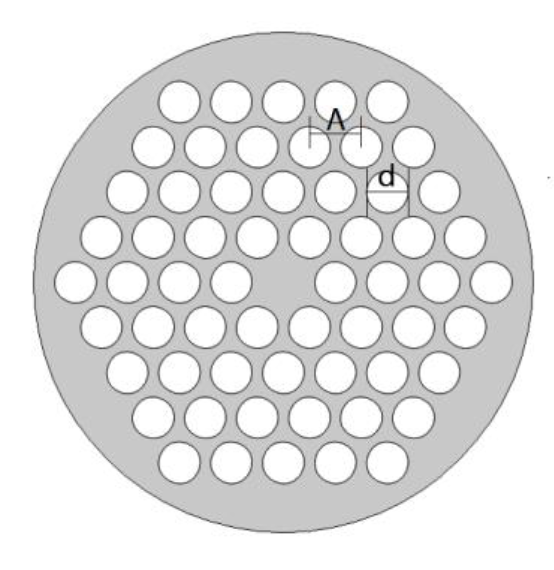
The cross profile of the PCF which has four hexagonal rings of air-holes is shown in Figure 2. d is the air-hole diameter, Λ is the distance between adjacent two air-holes and d / Λ is defined as the air filling factor (AFF). In this paper Λ is 2.3   μ m and d / Λ is set as 0.6, 0.7 and 0.8 respectively for different d. We set the pump power as 20 mW, the pulse width of the signal wave is 200 ns, and the wavelength of the pump wave is 1550 nm. Due to the melting point (−114.3 °C) and the boiling point (78.4 °C) of alcohol, the sensing temperature is set between 20 °C and 70 °C for this alcohol-filled fiber, and some key parameters for SBS fast light are described at this temperature range in this paper.
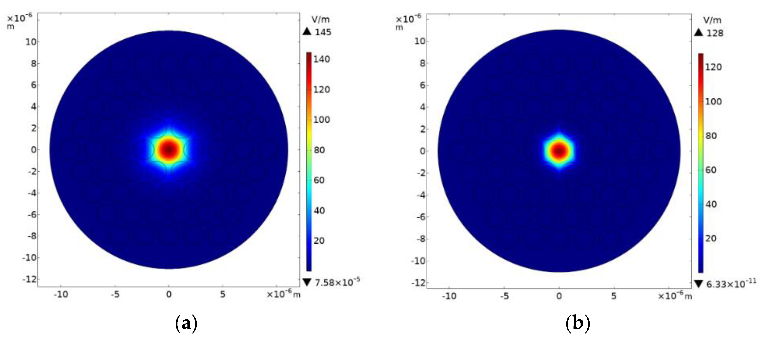
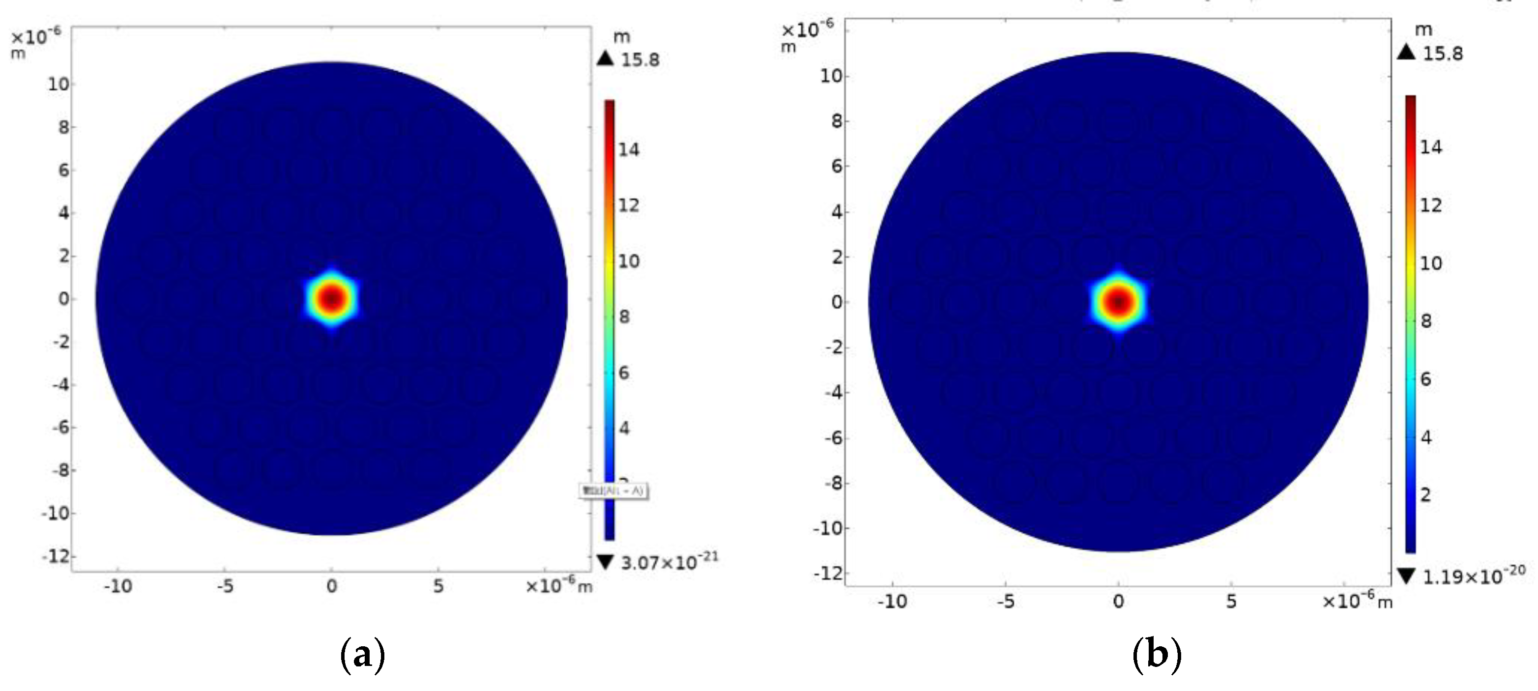
Figure 3 and Figure 4 depict the fundamental mode distribution of optical field and acoustic field in the filled and unfilled PCF when d / Λ is 0.8 and the sensing temperature is 20 °C. It can be seen that the filled and unfilled PCF have a greater difference on the distribution of the optical field and the acoustic field, this is because the optical field is confined in the core of the PCF due to the index difference with the air-holes. The acoustic field is confined in the core of the PCF. When the air-holes are filled with alcohol, the index of the air-holes increases so the index difference between the core and the cladding decreases, then the restrictions on the optical field is reduced, so the optical field distribution in filled PCF is larger than that of the unfilled PCF.
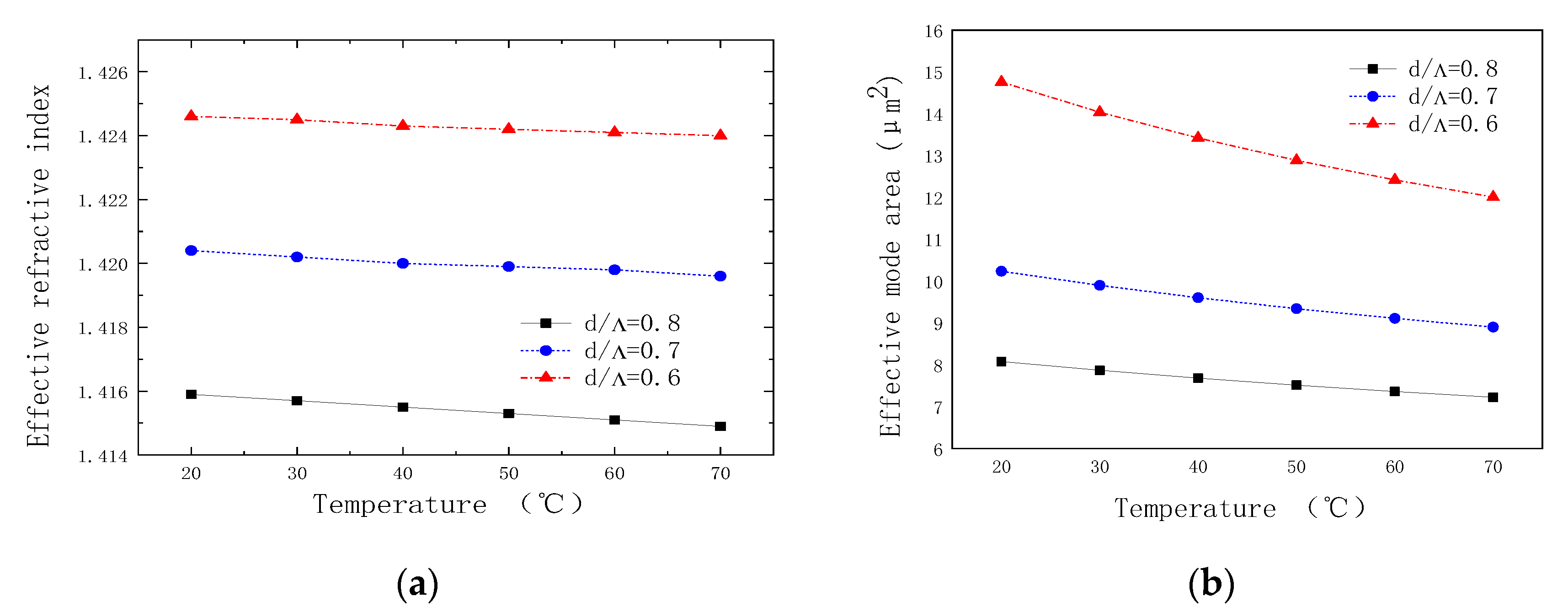
The variation of the effective refractive index of the PCF with different temperature and different AFF is shown in Figure 5a. The effective refractive index reduces when d / Λ increases at a given temperature. Compared to the change of quartz index with different temperature, the alcohol index changes largely and thus induces varying of the difference of the effective refractive index for the different temperatures. Figure 5b shows the effective mode field area varying with temperature in the filled PCF. It can be seen that the larger the d / Λ is, the smaller the effective mode field becomes, and when temperature goes up the effective mode field area gradually shrinks because of the reducing of the alcohol index with temperature rising. The effective mode field area variation reaches to 2.75   μ m while d / Λ is 0.6 at the temperature range of 20–70 °C.

4.2. The Brillouin Frequency Shift

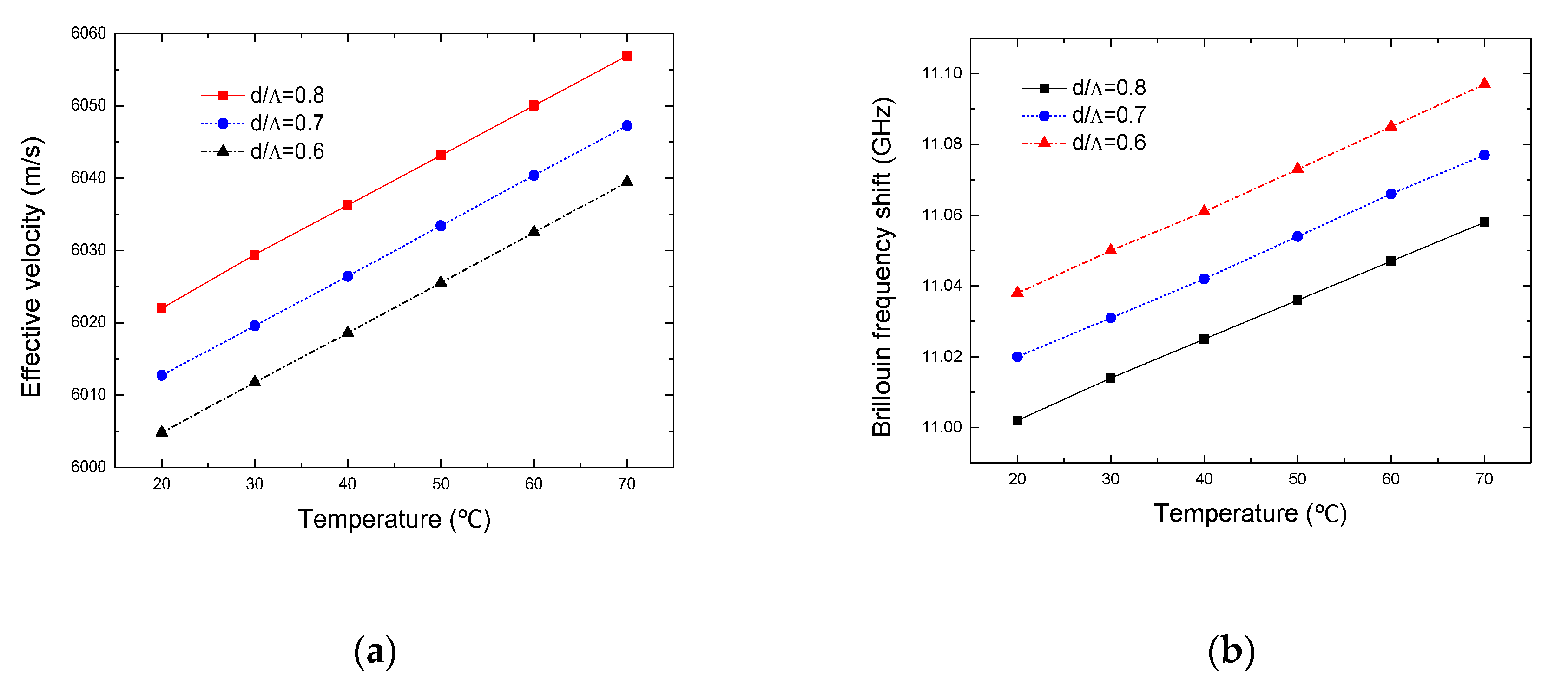
Figure 6 shows the variation of the effective acoustic velocity and the Brillouin frequency shift with temperature. It can be seen from Figure 6a that the effective acoustic velocity increases gradually with the rising of temperature, and there is a larger effective acoustic velocity corresponding with high d / Λ , this is because the effective refractive index decreases with the rising of temperature or with the increasing of d / Λ . Meanwhile these result in a small Brillouin frequency shift, which can also be seen from Figure 6b. The Brillouin frequency shift is different at about 11 GHz and the average difference per unit temperature is 1.15 MHz.

4.3. The Brillouin Threshold

Because the Brillouin absorption coefficient of the filled PCF is different at different temperatures, the Brillouin threshold value at different temperatures can be obtained from the Equations (11) and (12). Figure 7 depicts the changes of P max and P min at different d / Λ and temperature. When d / Λ increases, both P max , P min and their modifications reduce. Since larger d / Λ confine the transmission light into smaller regions to reduce SBS occurring in the area in the PCF, and for the same reason, the SBS occurs easily due to the shrinking of the effective mode field area as the temperature rises. The simulation result shows that the range of P max is from 913 mW to 1137 mW and the range of P min is from 0.18 mW to 0.23 mW while the effective transmission length is 10 m and d / Λ is 0.6.

4.4. The Temperature Response of the Fast Light

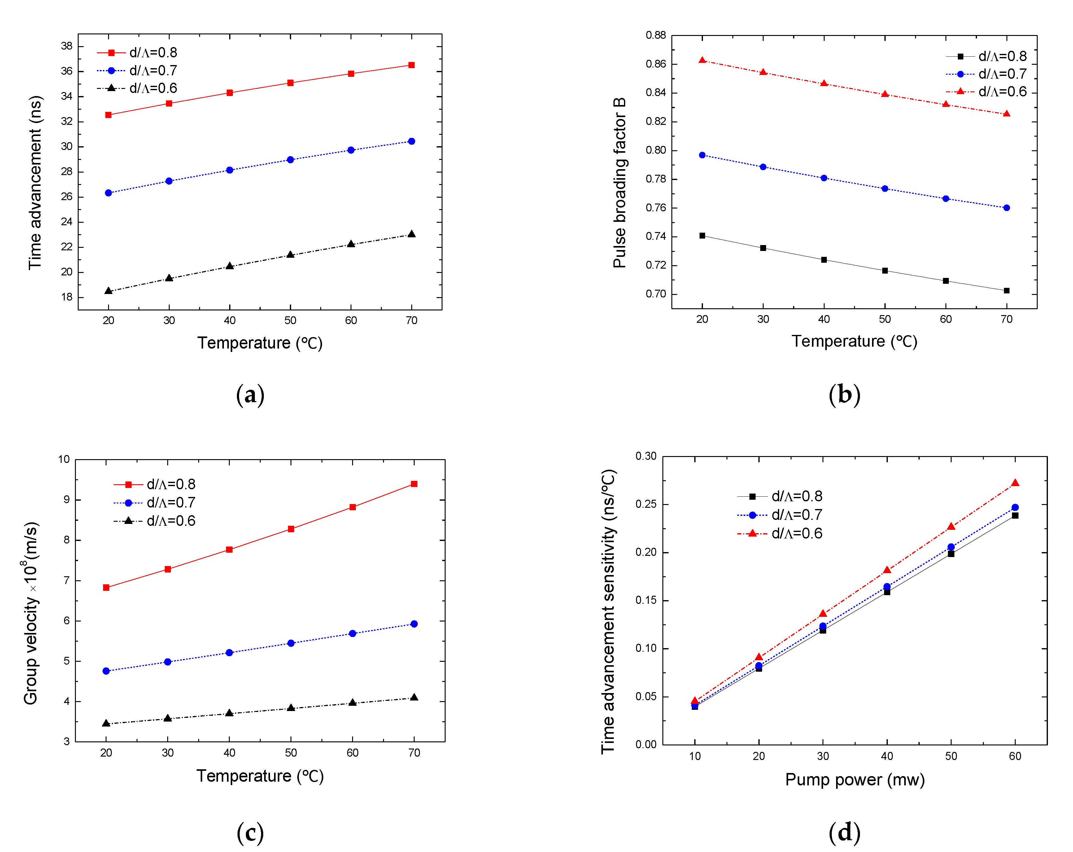
The variations of the time advancement, the pulse broadening factor, the velocity and the time advancement sensitivity of the signal light are shown in Figure 8. From Figure 8a it can be seen that the time advancement of the signal light increases with higher temperature and larger AFF. When temperature rises and AFF becomes larger, the effective mode field area shrinks, more light beams are confined in the fiber core, and then the SBS is enhanced. As d / Λ is 0.8, 0.7 and 0.6, the corresponding time advancement modifications of the signal light are 3.98 ns, 4.12 ns and 4.53 ns respectively. Obviously it is more sensitive for the time advancement modifications with the changes of temperature when the d / Λ is small, but the time advancement is inferior to that of the fast light for large d / Λ . The time advancement goes up to 36.52 ns at 70 °C while the d / Λ is 0.8. In Figure 8b, the pulse broadening factor decreases with temperature increasing. Fast light transmission means the attenuation of the signal pulse: the more obvious the fast light is, the greater the pulse attenuation becomes. Figure 8c shows the changes of the group velocity of the fast light with temperature. The group velocity gradually increases with the increase of temperature, and the variation range of the group velocity becomes larger for larger d / Λ . The figure shows the variation range is from 6.83 × 10⁸ m/s to 9.40 × 10⁸ m/s while the d / Λ is 0.8, and it is from 3.45 × 10⁸ m/s to 4.09 × 10⁸ m/s while the d / Λ is 0.6. This is because different d / Λ results in different effective refractive index and causes different group velocity. The sensitivity of the time advancement on temperature for different pump power is shown in Figure 8d. It can be seen that the time advancement is linearly related to pump power, and as mentioned above, the more sensitive the time advancement becomes, the smaller the d / Λ is, as well as the higher the pump power is. As shown in this figure, the sensitivity of the time advancement is only 0.045 ns/°C for the d / Λ of 0.6 and the pump power of 10 mW, but the sensitivity of the time advancement reaches to 0.272 ns/°C at a pump power of 60 mW, so it is feasible to enhance the sensitivity of the time advancement by increasing pump power.

4.5. The Shape of the Output Signal Pulse

Figure 9 describes the normalized signal pulse shape of the fast light. The black curve illustrates the pulse of the input signal light whose width is 200 ns. It can be seen that the shapes of the output signal pulses are narrower than the input pulse shape. Because the signal pulses are compressed in the fast light process, and the compression is more easily distinguished because of the larger time advancement due to higher temperature in alcohol-filled PCF. The signal pulses at different temperature are nearly overlapped in unfilled PCF as shown in Figure 9a, however they are clearly separated in the filled PCF as shown in Figure 9b.

5. Conclusions

The sensing characteristics of the SBS fast light in liquid-filled PCF for different temperatures (20–70 °C) are theoretically analyzed, an index-guided hexagonal PCF is proposed and an experimental setup is proposed to effectively realize temperature sensing. From simulated results we know that the liquid-filled PCF is more sensitive to temperature than the unfilled PCF. The main reason is the temperature sensitivity on the refractive index of liquid which causes remarkable changes of the effective refractive index of the whole PCF. Some parameters including the effective mode area, the Brillouin frequency shift, the SBS threshold value pump power and the SBS fast light parameters such as the time advancement, the pulse broadening factor and the group velocity are simulated for different temperature and different AFF in filled PCF. When the temperature rises from 20 °C to 70 °C, the Brillouin frequency shift, the time advancement and the group velocity of the signal light increase meanwhile the effective mode area and the pulse broadening factor decrease, and the variations of these parameters with temperature are similar to that with the AFF but opposite for the Brillouin frequency shift. The modification of the effective mode area with temperature is 2.72   μ m 2 when d / Λ is 0.6. The Brillouin frequency shift is about 11 GHz within the temperature range of 20–70 °C and the average difference per unit temperature is 1.15 MHz. The effective transmission length is 10 m and d / Λ is 0.6, the range of P max is from 913 mW to 1137 mW and the range of P min is from 0.18 mW to 0.23 mW, and the variation range of the group velocity is from 3.45 × 10⁸ m/s to 4.09 × 10⁸ m/s, meanwhile the modification of the time advancement is 4.53 ns, and while the d / Λ is 0.8 the time advancement reaches to 36.52 ns at 70 °C. These results are of importance for designing fast-light temperature sensors, and future work will be focused on the investigation of larger time advancement and more sensitive sensing efficiency of SBS fast light by optimizing the structure of PCF or by filling other liquids with a bigger temperature coefficient in PCF.

Author Contributions

Conceptualization, J.L., S.N. and S.H.; methodology, J.L. and S.N.; validation, J.L. and S.N.; formal analysis, J.L.; investigation, J.L., S.N. and D.W.; writing—original draft preparation, S.N.; writing—review and editing, J.L. and S.H.; supervision, S.H.; project administration, X.L.; funding acquisition, S.H. All authors have read and agreed to the published version of the manuscript.

Funding

This work was supported in part by the National Natural Science Foundation of China (No. 61665005) and the HongLiu First-class Disciplines Development Program of Lanzhou University of Technology.

Conflicts of Interest

The authors declare no conflict of interest.

References

  1. Hau, L.V.; Harris, S.E.; Dutton, Z.; Behroozi, C.H. Light speed reduction to 17 metres per second in an ultracold atomic gas. Nature 1999, 397, 594–598. [Google Scholar] [CrossRef]
  2. Kash, M.M.; Sautenkov, V.A.; Zibrov, A.S.; Hollberg, L.; Welch, G.R.; Lukin, M.D.; Rostovtsev, Y.; Fry, E.S.; Scully, M.O. Ultraslow group velocity and enhanced nonlinear optical effects in a coherently driven hot atomic gas. Phys. Rev. Lett. 1999, 82, 5229–5232. [Google Scholar] [CrossRef] [Green Version]
  3. Chu, S.; Wong, S. Linear pulse propagation in an absorbing medium. Phys. Rev. Lett. 1982, 48, 738–741. [Google Scholar] [CrossRef]
  4. Stenner, M.D.; Gauthier, D.J.; Neifeld, M.A. The speed of information in a ‘fast-light’optical medium. Nature 2003, 425, 695–698. [Google Scholar] [CrossRef]
  5. Sharping, J.E.; Okawachi, Y.; Gaeta, A.L. Wide bandwidth slow light using a Raman fiber amplifier. Opt. Express 2005, 13, 6092–6098. [Google Scholar] [CrossRef] [PubMed]
  6. Okawachi, Y.; Bigelow, M.S.; Sharping, J.E.; Zhu, Z.; Schweinsberg, A.; Gauthier, D.J.; Boyd, R.W.; Gaeta, A.L. Tunable All-Optical Delays via Brillouin Slow Light in an Optical Fiber. Phys. Rev. Lett. 2005, 94, 153902. [Google Scholar] [CrossRef]
  7. Dahan, D.; Eisenstein, G. Tunable all optical delay via slow and fast light propagation in a Raman assisted fiber optical parametric amplifier: A route to all optical buffering. Opt. Express 2005, 13, 6234–6249. [Google Scholar] [CrossRef] [Green Version]
  8. Sinha, R.K.; Kumar, A.; Saini, T.S. Analysis and Design of Single-Mode As2Se3-Chalcogenide Photonic Crystal Fiber for Generation of Slow Light with Tunable Features. IEEE J. Sel. Top. Quantum Electron. 2015, 22, 287–292. [Google Scholar] [CrossRef]
  9. Hassani, A.; Dupuis, A.; Skorobogatiy, M. Low loss porous terahertz fibers containing multiple subwavelength holes. Appl. Phys. Lett. 2008, 92, 071101. [Google Scholar] [CrossRef]
  10. Pisco, M.; Ricciardi, A.; Campopiano, S.; Caucheteur, C.; Mégret, P.; Cutolo, A.; Cusano, A. Fast and slow light in optical fibers through tilted fiber Bragg gratings. Opt. Express 2009, 17, 23502–23510. [Google Scholar] [CrossRef]
  11. Steinvurzel, P.; Eggleton, B.; De Sterke, C.M.; Steel, M.J. Continuously tunable bandpass filtering using high-index inclusion microstructured optical fibre. Electron. Lett. 2005, 41, 463. [Google Scholar] [CrossRef]
  12. Han, T.; Liu, Y.; Wang, Z.; Zou, B.; Tai, B.; Liu, B. Avoided-crossing-based ultrasensitive photonic crystal fiber refractive index sensor. Opt. Lett. 2010, 35, 2061–2063. [Google Scholar] [CrossRef]
  13. Geng, Y.; Li, X.; Tan, X.; Deng, Y.-L.; Hong, X. Compact and Ultrasensitive Temperature Sensor with a Fully Liquid-Filled Photonic Crystal Fiber Mach–Zehnder Interferometer. IEEE Sens. J. 2013, 14, 167–170. [Google Scholar] [CrossRef]
  14. Monfared, Y.E.; Ponomarenko, S.A. Slow light generation via stimulated Brillouin scattering in liquid-filled photonic crystal fibers. Optik 2016, 127, 5800–5805. [Google Scholar] [CrossRef]
  15. Song, S.; Jung, A.; Oh, K. High-Temperature Sensitivity in Stimulated Brillouin Scattering of 1060 nm Single-Mode Fibers. Sensors 2019, 19, 4731. [Google Scholar] [CrossRef] [Green Version]
  16. Kalosha, V.P.; Chen, L.; Bao, X. Slow and fast light via SBS in optical fibers for short pulses and broadband pump. Opt. Express 2006, 14, 12693–12703. [Google Scholar] [CrossRef]
  17. Kalosha, V.P.; Chen, L.; Bao, X. Slow light of subnanosecond pulses via stimulated Brillouin scattering in nonuniform fibers. Phys. Rev. A 2007, 75, 021802. [Google Scholar] [CrossRef]
  18. Qin, G.; Sotobayashi, H.; Tsuchiya, M.; Mori, A.; Suzuki, T.; Ohishi, Y. Stimulated Brillouin Scattering in a Single-Mode Tellurite Fiber for Amplification, Lasing, and Slow Light Generation. J. Lightwave Technol. 2008, 26, 492–498. [Google Scholar] [CrossRef]
  19. Cheng, T.; Liao, M.; Gao, W.; Duan, Z.; Suzuki, T.; Ohishi, Y. Suppression of stimulated Brillouin scattering in all-solid chalcogenide-tellurite photonic bandgap fiber. Opt. Express 2012, 20, 28846–28854. [Google Scholar] [CrossRef]
  20. Dasgupta, S.; Poletti, F.; Liu, S.; Petropoulos, P.; Richardson, D.J.; Grüner-Nielsen, L.; Herstrøm, S. Modeling Brillouin Gain Spectrum of Solid and Microstructured Optical Fibers Using a Finite Element Method. J. Light. Technol. 2010, 29, 22–30. [Google Scholar] [CrossRef]
  21. Hou, S.; Wen, B.; Li, H.; Liu, Y.; Wang, D.; Li, X.; Lei, J. Effects of SBS slow light on super-Gaussian pulses in fibers. Opt. Commun. 2014, 323, 13–18. [Google Scholar] [CrossRef]
  22. Huang, M.; Huang, J. Temperature Dependence of Brillouin Scattering Spectrum for High Nonlinear Photonic Crystal Fiber. Opto Electron. Eng. 2011, 38, 6–10. [Google Scholar]
  23. Jain, V.; Sharma, S.; Saini, T.S.; Kumar, A.; Sinha, R.K. Design and analysis of single-mode tellurite photonic crystal fibers for stimulated Brillouin scattering based slow-light generation. Appl. Opt. 2016, 55, 6791. [Google Scholar] [CrossRef] [PubMed]
  24. Zhao, L. Influence of environment temperature wide-range variation on Brillouin shift in optical fiber. Acta Phys. Sin. 2010, 59, 6219–6223. [Google Scholar]
Figure 1. The proposed experimental setup. DFB: distributed feedback laser; EDFA: erbium-doped fiber amplifier; OC: optical coupler.
Coatings 10 01123 g001
Figure 2. The cross profile of the photonic crystal fiber (PCF).
Coatings 10 01123 g002
Figure 3. Distribution of optical fundamental mode in the proposed (a) filled and (b) unfilled PCF at 20 °C.
Coatings 10 01123 g003
Figure 4. Distribution of acoustic fundamental mode in the proposed (a) filled and (b) unfilled PCF at 20 °C.
Coatings 10 01123 g004
Figure 5. (a) the effective refractive index and (b) the effective mode area vary with temperature.
Coatings 10 01123 g005
Figure 6. (a) the effective velocity (b) the Brillouin frequency shift vary with temperature.
Coatings 10 01123 g006
Figure 7. (a) P max and (b) P min vary with temperature.
Coatings 10 01123 g007
Figure 8. (a) Time advancement, (b) pulse broadening factor and (c) group velocity of signal light varies with temperature. (d) Time advancement sensitivity varies with pump power.
Coatings 10 01123 g008
Figure 9. The output waveform of pulse signal for different temperature in (a) ethanol-unfilled and (b) ethanol-filled PCF.
Coatings 10 01123 g009
Publisher’s Note: MDPI stays neutral with regard to jurisdictional claims in published maps and institutional affiliations.