Abstract
The electromagnetic rail catapult is a device that converts electrical energy into kinetic energy, which means that the strength of electrical energy directly affects the muzzle speed of armature. In addition, the electrical conductivity, electromagnetic rails and armature surface roughness, and the holding force of the rail are influencing factors that cannot be ignored. However, the electric ablation on the surface of the electromagnetic rails caused by high temperatures seriously affects the service life performance of the electromagnetic catapult system. In this study, electrochemically deposited nickel-phosphorus and nickel-molybdenum alloy coatings are plated on the surface of electromagnetic iron rails and their effects on the reduction of ablation are investigated. SEM (scanning electron microscopy) with EDS (energy dispersive spectroscopy) detector, XRD (X-ray diffraction), 3D optical profiler, and Vickers microhardness tester are used. Our results show that the sliding velocity of the armature decreases slightly with the increased roughness of the rail coating surface. On the other hand, the area of electric ablation on the rail surface is inversely related to the hardness of the rail material. The electrically ablated surface areas of the rails are in: annealed nickel–molybdenum < nickel–molybdenum < annealed nickel–phosphorus < nickel–phosphorus < iron material. Heat treatment at 400 and 500 °C, respectively for Ni–P and Ni–Mo alloys, significantly increases hardness due to the precipitation of intermetallic compounds such as Ni3P and Ni4Mo phases. Comprehensive data analysis shows that the annealed nickel–molybdenum coating has the best electrical ablation wear resistance. The possible reason for that might be attributed to the high hardness of the heat-treated nickel–molybdenum coating. In addition, the thermal resistance capability of molybdenum is better than that of phosphorus, which might also contribute to the high wear resistance to electric ablation.
1. Introduction
Recently, the electromagnetic rail catapult has shown its potential to replace traditional guns due to the fact that it can accelerate a projectile to its super high speed, has a simple design, and has good security [1]. The electromagnetic rail catapult is composed of control circuits, pulse power supplies, metal rails arranged in parallel, and armatures (including projectiles) [2]. A schematic diagram of the electromagnetic rail catapult is shown in Figure 1; when interacting with the currents passed through the rails and armature at that time, the magnetic fields were generated. The magnetic field line formed on a clockwise circle around the positive rail and on a counterclockwise circle around the negative rail, view from the leading edge. The net magnetic field between the rails is in the vertical direction. So, the Lorentz force is directed perpendicularly to the magnetic field and contributes to the direction of the armature movement. This system, which does not require chemical energy propellants and uses electrical energy as electro power, has been valued by many countries [3,4,5,6]. The Lorentz force will be increased by increasing the current. This means a large current is needed to accelerate the projectile to hypersonic velocities.
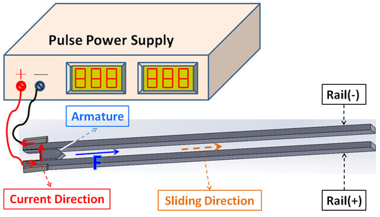
Figure 1.
Schematic diagram of electromagnetic rail catapult.
However, the large current high-speed electric sliding contact between the armature and the rails can lead to the problem of rail ablation. The rail’s electrical ablation is one of the most significant problems, needing to be solved urgently for rail catapult operation. The main reasons are that high temperature, large speed and high current lead to change the original smooth surface of the metal rail [7,8,9,10,11]. Seeking technology that can solve or improve the service life of electromagnetic catapult rails has become the key to whether electromagnetic rail catapult can be practically applied.
To endure severe environments such as extreme mechanical wear and high-temperature thermal shock during the high-velocity propulsion, rail materials should have high electrical conductivity, high hardness, high thermal conductivity and high resistance to wear [12]. The application of the appropriate coating on rail has been reported as an effective approach in reducing the degradation of rail [12,13,14,15]. Colombo et al. reported that the wear and spark erosion of the copper rails had been reduced after the rails were coated with TaN and TiN by Plasma Source Ion Implantation and Ion Beam Enhanced Deposition techniques [12]. Siopis et al. [13] performed a systematic investigation by the Ashby method to select a rail material that would maximize magnetic energy for performance and durability for economic viability. Their results suggested that a hybrid rail material with an electrically conductive substrate and a damage-resistant surface layer consisting of tungsten, chromium, nickel, or tantalum can accomplish these two contradictory goals. Watt electroplated Al on the surface of UNS C15725 Glidcop Al-25, an aluminum oxide (0.25 wt.%) dispersion-hardened copper alloy, and found that Al coating can effectively inhibit the occurrence of gouge and wear [14]. Due to its high hardness, hard chromium coatings were electroplated on the surface of rail materials to reduce the damage of the rails [15].
The core component of the pulse power supply in this study is the capacitor stack. Therefore, the life of the capacitor is the key component that determines whether the system is operating normally or not. According to the information provided by the capacitor supplier, the life of the capacitor is positively related to the operating temperature of the part. For the evaluation of the service life of the capacitor, if the capacitor has been kept operating at a temperature below 75 °C, the capacitor can maintain normal operation for at least 5 years (if it operates 1 cycle per day, it is estimated that it can operate at 1800 cycles). Another key component is the electromagnetic rail. If the rail is made of a single metal material, it cannot withstand the damage to the rail surface caused by high voltage (300 DCV) and the rail can be used only one to two times. Therefore, our team applied nickel-based coating processing to the rails, hoping to improve this puzzle.
For the deposition of coatings, electroless plating and electroplating offer many advantages such as low cost, versatility and the production of a wide range of metallic materials. Among various types of coatings fabricated through electroless plating and electroplating, nickel-based alloy coatings are widely employed owing to their remarkable properties which include good corrosion, low friction coefficient and good wear resistance. Moreover, with subsequent thermal treatment hardness of Ni-based coatings can be even higher than that of hard chromium coatings [16,17,18,19,20,21]. Ni-based alloy coatings are widely applied in various industries. However, the applications of Ni-based coatings in rail guns have rarely been studied. Based on our previous studies [22,23,24,25], electroless plated nickel-phosphorus coatings are characterized by good conductivity, good corrosion resistance, no pinholes, low friction coefficient, stable production and low price and the nickel-molybdenum electrodeposits are known for their high hardness, abrasion resistance and good thermal resistance. Therefore, in this study, nickel-phosphorus and nickel-molybdenum alloy coatings were plating on the surface of the iron rails of the electromagnetic rail and their effects on the reduction of ablation were investigated and compared.
2. Experimental Equipment and Planning
This study is divided into two parts, including the preparation of experimental equipment and the electromagnetic rail’s surface improvement plan. The first part is to build a small set of electromagnetic rail catapult experimental equipment to facilitate the valuation of the wear of the contact surface between the armature and the electromagnetic catapult conductive rails. The second part is the electrochemical deposition and modification of the surface of the electromagnetic catapult conductive rails. The nickel–phosphorus and nickel–molybdenum alloy is coated on the surface of the iron rail to evaluate the improvement of the electrical ablation on the conductive rail.
2.1. Preparation of Small Electromagnetic Catapult Experiment Equipment
Figure 2a is a function diagram of an electromagnetic catapult, which can be electro modulated according to the experimental requirements. This figure shows that the pulse power supply is modulated from 110 ACV to the experiment requires AC potential (0~600 ACV), then rectifies DCV, and then charges the capacitor stack. Regarding the function to provide pulse electricity power for the energizing section of the electromagnetic rail [26,27,28,29,30], in this study, the capacitor stack contained 42 capacitors (2200 μF/450 DCV) and was configured in parallel to obtain a total capacitance of 0.0924 F. In order to respond the electrical limitations of component, the operating voltage set in this experiment was 300 DCV. It can be calculated from Equation (1) that the output energy of the pulse power supply in this experiment is 4158 Joules.
where C is the total capacity (unit: Farad) and V is the pulse voltage (unit: Voltage).
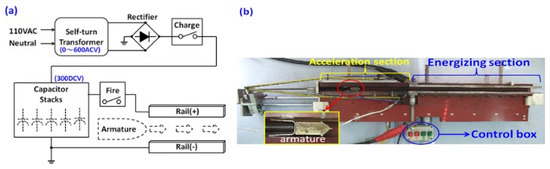
Figure 2.
Experimental device (a) control circuit; (b) electromagnetic rail catapult and armature.
This experimental device of electromagnetic rail catapult is shown in Figure 2b. The whole set of catapult length is 1m which is composed of an acceleration section and an energizing section. The length of the acceleration section is 0.4 m, the mechanical ejection equipment in this section is used to verify and compare the efficiency of the electromagnetic catapult. The muzzle velocity of the armature (27 g) obtained by pure mechanical ejection was about 7.6 m/s which was measured using an optical grid type speedometer (ProChrono Co., Rockford, IL, USA). The substrate of electromagnetic rails are made of medium carbon steel, its electrical conductive resistance is 0.224 Ω (Refer to Table 3). Each rail’s size is 0.6 × 0.035 × 0.01 m3. The support structure of the rail is made of bakelite to ensure good electrical insulation and operator safety. In order to have good contact between armature and rails, a U-shaped elastic tail with an outward angle of 3.5°, which was made from elastic steel sheet (used stainless steel model 304: Chromium 18%, Nickel 8%, Manganese 2%), was used as the armature carrier. The front arrow weight was made of non-conductive rubber. The armature is displayed in Figure 2b.
During the experimental operation, the capacitor stack was first charged to 300 DCV. When the fire button is pressed, it will provide the mechanical force to push the armature to generate initial speed, at the same time, 300 DCV from the capacitor stack is connected to the energizing section. When the armature enters the metal rail, the overall electrical circuit is fully connected by the physical contact between the armature and the rails. The capacitor stack begins to release current on the rails and at the same time generates Lorentz force, which promotes the acceleration of the armature. The capacity of the capacitor stack is gradually discharged until it is completely released (capacitor stack voltage drops to 0 DCV).
The sliding speed of the armature on the rail is measured with an electromagnetic field sensor (PASCO CI-6520A, Roseville, CA, USA) and dedicated software (PASCO Capstone, version: 1.12.0). The installation distance between these two electromagnetic sensors is fixed at 0.1 m. When the armature enters the detection range of the electromagnetic sensor, the screen on dedicated software will display a convex wave of the magnetic field strength. The muzzle velocity of the armature is calculated by simply dividing the distance between the two electromagnetic sensors by the time difference measured with the electromagnetic sensors. See Equation (2).
The definition of speed is the change in position (∆x, the last position minus the initial position,) divided by the time interval (∆t).
2.2. Deposition Process of Nickel–Phosphorus and Nickel–Molybdenum Coatings
Prior to each experiment, the rail was cleaned with acetone with ultrasonic agitation for 10 min, alkali washed in a 10% NaOH solution of 40 °C for 15 min, pickled with a 50% HCl solution for 30 s, and washed by deionized water.
Nickel–phosphorus alloy coatings were used with nickel sulfate electrolyte, electroless plated at 87 °C for 2 h from a bath containing nickel sulfate hexahydrate, sodium lactate, amino acid glycine, Sodium hypophosphite, potassium iodate and lead nitrate. The pH of the plating bath was adjusted to 4.7, and the volume flow rate was 3 L/min. The details of bath compositions can be seen in Table 1.

Table 1.
Nickel–phosphorus alloy plating solution composition.
Nickel–molybdenum alloy coatings were electroplated at 25 °C for 2 h from an electrolyte containing nickel sulfate hexahydrate, sodium molybdate dihydrate, and sodium citrate. The pH of the plating was adjusted to 9.5, the current density was 5 A/dm2, and the volume flow rate was 3 L/min. The details of bath compositions can be seen in Table 2.
Table 2.
Nickel–molybdenum alloy plating solution composition.
Heat treatment was operated at 400 and 500 °C in an argon atmosphere for nickel–phosphorus and nickel–molybdenum-coated rails, respectively. Heat treatment lasted for 1 h and then the samples were cooled to room temperature.
2.3. Characterization of Rails
The contact resistance between armature and rails was measured by a Digital Multi-meter (PICOTEST M3500A 6½ digit, Kaohsiung, Taiwan). The measurement method uses “4-wire” static measurement, sandwiching a copper piece between the armature and the rails, so that the test rod can be stably clamped.
The rail after the experiment was cut into test pieces of about 0.01 × 0.01 m2, which were placed in acetone and clean water for ultrasonic cleaning and drying. The surface microstructure and composition of the samples were observed using a JEOL JSM-F100 scanning electron microscopy (SEM) (Tokyo, Japan) with an energy dispersive spectroscopy (EDS) detector (Tokyo, Japan). Using Bruker D2 PHASER diffractometer (Karlsruhe, Germany), using CuKα radiation, X-ray diffraction (XRD) structure analysis was performed. The surface roughness was measured using a Chroma 7502 3D optical profiler (Taoyuan, Taiwan). The Digital microhardness tester (HVS-1000) (Taipei, Taiwan) was used to measure the hardness. Load at 300 gf, and calculate the average hardness after 9 tests (result in Table 3).
Table 3.
Material properties of the experimental rails.
3. Results and Discussion
The main objective of this study is to find coating materials that can reduce or prevent metal rail from ablation. The focus of the analysis is to confirm the properties of the coating materials before the catapult experiment. The velocity of the catapult is affected by the electrical energy, armature and rail material characteristics, and the analysis of the area and surface properties of the surface of the rail after electric catapult; in order to explore the optimal coating in the experiment and the possible cause analysis.
3.1. Rail Material/Coating Properties
A total of five types of rail surface materials was detected in this study, including iron rails, nickel–phosphorus-coated rails, heat-treated nickel–phosphorus-coated rails, nickel–molybdenum-coated rails, heat-treated nickel–molybdenum-coated rails. The nickel–phosphorus coating prepared in this study has a thickness of about 15~20 µm and a phosphorus content of about 8 to 12 wt.%. The nickel-molybdenum coating has a thickness of about 30~35 µm and a molybdenum content of about 28 to 31 wt.% (see Figure 3). Table 3 is a list of the results obtained for hardness, contact resistance and surface’s average roughness.
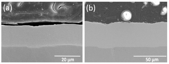
Figure 3.
SEM images of coating cross-section: (a) Ni–P Coating; (b) Ni–Mo Coating.
The heat treatment temperature is selected based on past research experience and literature that recommends the heat treatment temperature of nickel–phosphorus to be set at 400 °C/1 h and the heat treatment temperature of nickel–molybdenum to be set at 500 °C. It shows from Table 3 that the hardness (215 HV) of the pristine iron substrate is lowest among all tested samples. The hardness of nickel–phosphorus-coated and nickel–molybdenum-coated rail is 512 and 720 HV, respectively. After annealing at 400 °C for 1 h, the hardness of nickel–phosphorus-coated rail increased to 650 HV. On the other hand, the hardness of annealing nickel–molybdenum-coated rail increased to 1045 HV after heat treatment at 500 °C. It is believed that heating a Ni–P coating at temperatures of 400 °C for 1 h increases hardness which can be ascribed to the solid solution strengthening effect as a result of the precipitation of intermetallic compound Ni3P during the heat treatment period [31]. Similarly, the increase in hardness of the annealed nickel–molybdenum coating is attributed to the solid solution strengthening effect of Ni4Mo precipitation [18].
In catapult processes, the heat conduction between the armature and rails is an important factor for the temperature rise of rails. The ablation and wear caused by the rise of temperature would affect the performance and service life of the rail. A low contact resistance is thus important for selection of rail material. It shows from Table 3 that except for the annealed nickel–phosphorus-coated rail, contact resistance of all rails is slightly higher than 0.2 Ω. For the annealed nickel–phosphorus-coated rail it is about 0.186 Ω, which is lower than 0.2 Ω. The annealed nickel–phosphorus-coated rail has the lowest contact resistance might be ascribed to the fact that the grain size of nickel–phosphorus increases with the heat treatment temperature, resulting in the change of interface volume fraction and its properties [32]. The surface roughness is another factor that will influence the sliding contact between solid armature and rail. As shown in Table 3, the surface roughness of these rails is in the order: iron rail < Ni–P-coated rail < heat-treated Ni–P-coated rail < Ni–Mo-coated rail < heat-treated Ni–Mo-coated rail. The surface roughness is lowest for pristine iron rail (Ra 1.52 µm, Sa 4.41 µm). The surface roughness increases after coating which might be attributed to the surface after the coating is not ground and polished. The slight increase in surface roughness after heat treatment should be due to the effect of grain coarsening.
3.2. Influencing Factors of Muzzle Velocity of Armature
When the electric energy was fixed at 300 DCV, the muzzle velocity of the armature was measured, rails with or without different surface coatings were tested. Our results showed that the muzzle velocities of the armature vary from 84 to 91 m/s depending on the rail materials used (See Figure 4). The muzzle velocity of the armature obtained with different rails is in the following order: iron rail > Ni–P-coated rail > heat-treated Ni–P-coated rail > Ni–Mo-coated rail > heat-treated Ni–Mo-coated rail. It is evident that rail material will affect the muzzle velocity of the armature. As mentioned in the last section, the contact resistance and surface roughness of rail with different surface coatings are different. Figure 4 displays the variation of the muzzle velocity of the armature with a surface roughness of various rail materials. It appears that the muzzle velocity of armature decreases with the increasing surface roughness of the rails, while the contact resistance of the rails has an insignificant effect on muzzle velocity. The high value of surface roughness can increase the friction leading to energy loss, and as a result, the muzzle velocity decreases.
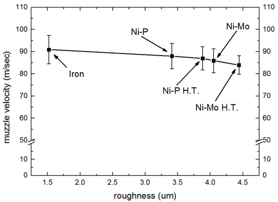
Figure 4.
Surface roughness against armature velocity.
3.3. Wear Analysis of the Rail’s Surface
After one shot, the rails were removed. A segment of removed rail was sectioned at a position 0.13 m from the beginning of the energizing section and a wear analysis was performed on this 0.13 m long rail to investigate the effect of rail material on electrical ablation shows the worn surfaces of various rails, as shown in Figure 5, the armature catapult was moving from left to the right.
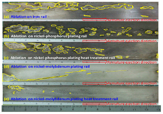
Figure 5.
Surface ablation morphology of different rail. (unit: cm).
As the armature contacted with rails that produced a discontinuous and rapid electrical friction and electrical ablation, the worn area, which was enclosed by a colored line, can be clearly seen on the surface of all rails. Figure 6 shows the ratio of the ablated area to the total area which was estimated using image J software (version: 1.53a) for five tested rail materials. It can be seen that the ablated ratio of the iron rail is 19.5%, Ni–P-coated rail is 12.9%, annealed Ni–P-coated rail is 11.6%, Ni–Mo-coated rail is 4.9% and annealed Ni–Mo-coated rail is 1.1%. It is clear that some rail materials resist ablation better than others. It is known that the better wear resistance is in accordance with Archard’s law wherein the wear resistance is directly proportional to the micro-hardness [33]. Calculated from the surface damage ratio of the rail, the ratio of nickel–molybdenum to iron is about 1:17.7 (refer to Figure 6); therefore, it is estimated that the nickel–molybdenum rail can use above 15 cycles. Therefore, the result that the heat-treated Ni–Mo-coated rail which has the highest hardness among all samples, and is expected to have the highest wear resistance in comparison with the other rail materials.
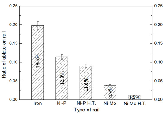
Figure 6.
Ratio of ablated area to the rail area after catapult test.
In Figure 7, 3D profiles show the annealed nickel–phosphorous coating rail before and after catapult. Table 4 shows the rail’s surface detected data by the 3D optical profiler. It shows the surface roughness of rails coated with annealed nickel–phosphorus is greater after catapulting (ΔRa = 5.67 µm, ΔSa = 6.32 µm); the surface roughness of annealed nickel–molybdenum-coated rail after catapult is smaller than before catapult. The possible reason for that can be explained as the annealed nickel–molybdenum-coated rail has the highest electrical resistance, resulting in less current appearing in the contact surface.
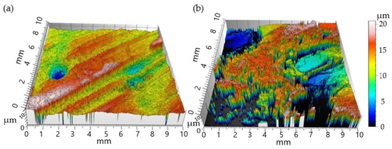
Figure 7.
The 3D profiles for annealed Ni–P plating rail surfaces (a) before catapult; (b) after catapult.
Table 4.
The surface roughness of various rails.
3.4. Analysis of Surface Morphology, Elements and Structure of the Electrical Ablation Zone
In order to analyze the microscopic condition of the rail surface after catapult, the ablated junction area of the rail after the experiment was appropriately sliced and cut into small test pieces of 15 × 15 × 5 mm3. SEM, EDS and XRD analyses were performed to observe the ablated rail surface. The ablation zone is divided into three grades from high to low: severe, moderate and light.
From the experimental results of ejecting the armature with the tension spring under the non-energized state and the observation and analysis of the surface morphology after catapult, it can be seen that the wear of the rail surface caused by the mechanical sliding friction after one ejection is almost non-existent. This is because the armature in this study is made of elastic spring steel into a U shape (the tail has an external opening angle of about 3.5°), and the clamping force applied to the armature by the movement of the rail during ejection is just sufficient to support the armature and the rail contact and maintain the ejection until it leaves the rail. Therefore, we can infer that in this study, in any rail surface, the surface wear caused by pure mechanical friction of the armature can be ignored.
We infer that the possible mechanism of rail sliding electric friction and wear is as follows: in the energized state of the armature ejection, the armature is pushed by the electromagnetic force and slides through the conductive rail at a large speed; the initial wear of the rail contact surface should be caused by the large current passing through the rail and the armature contact interface, leading to the contact area to be softened by large Joule heat, so that the material can possibly become half-melted-like and fluid as it encounters the frictional counter body and compresses; part of the softened and fluid material peels off and becomes the third body with metal lubricity. So, during the armature move on the metal rail, the contact area of the rail surface would be subjected to the interaction affected of current ablation, mechanical friction of the counter body, and the lubrication of the molten third body (debris). This results in the micro-morphology formation of irregular flaking pits, adhesions, and flow marks in the wear area. After ejection experiments, the EDS detect the worn area of the coating’s rail also shows that in addition to the nickel alloy coating’s original material elements, there also exist iron elements; this means that the armature iron material becomes the third body and transfers to the worn surface of the nickel alloy coating’s rail.
In addition, from the visual field of tribology; during the period of electromagnetic ejection armature analysis, part of the pulse electric energy released by the capacitor stack is disappeared, caused by the melting of the contact metal material, and the remaining energy is used to push the armature forward. If the ability of anti-thermal resistance of the coatings material is strong, it would be hard to soften and form a molten metal lubricity substance with fluidity, which makes the frictional resistance between the armature and the rail interface larger, resulting in a decrease in the armature speed. This also can be confirmed by the results of the Ni–Mo and annealed Ni–Mo coating rail in this study, which have a higher melting point, so that the ejection armature speed is slightly reduced than other rails. The damaged area on the surface of the annealed nickel–molybdenum coating rail is minimized.
Figure 8 shows the SEM photographs of various rail types of electric ablation areas and Table 5 is the EDX instrument analysis of all types of rails surface after catapult. All of the detection points are random. In addition, for convenience, the melting substance of the armature will be called the third substance.
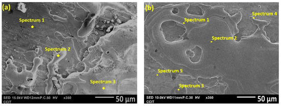
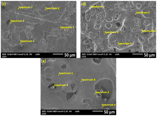
Figure 8.
The SEM photographs of various rail types of electric ablation areas after catapult: (a) iron rail; (b) Ni–P rail; (c) annealed Ni–P rail; (d) Ni–Mo rail; (e) annealed Ni–Mo rail.
Table 5.
The EDX instrument analysis of all type rails surface after catapult.
Figure 8a shows the ablated area of the iron rail surface. According to the proportion of elements analysis by the EDX instrument, ref to Table 5, the proportion of iron rail in spectrum 1 is as high as Fe at 95.2 wt.%, and the proportions of other elements (C, Co, Cr, Ni, Mn) are very low, and from the picture from SEM, it is observed in spectrum 1 that there is no obvious electric ablation on the surface of the iron rail, only slight scratches, which can prove that the surface of this area is not damaged. In contrast, the proportion of Fe in spectrum 2 and spectrum 3 decreased significantly, and the proportion of the remaining elements (C, Co, Cr, Ni, Mn) increased, and it is judged from the SEM pictures that the surface of the iron rail is covered or sticky with a third substance. It is sufficient to prove that the surface of this area has obvious electric ablation phenomena, indicating the degree of electric ablation is severe.
Figure 8b shows the electric ablation area on the nickel–phosphorus-coated rail after the catapult test. A large number of irregularly shaped craters on the surface can be clearly seen. As shown in Table 5, the EDS analysis of spectrum 2 revealed that Fe (95.5 wt.%) is the major element. It looks like the third substance, then transferred to and covered the surface of nickel–phosphorus-coated rail; Ni (40.7 wt.%) and Fe (35.9 wt.%), represents major elements in the spectrum 3 region, indicating that this area is only partially covered by the steel from the armature. Most of the accumulated material is iron. However, this indicates that the degree of electric ablation is moderate.
Figure 8c is the electric ablation area of the annealed nickel–phosphorus plated rail. Ref to Table 5 is EDS analysis, in spectrum 2, although there is irregular armature Fe transfer and coverage, shows that the Fe in this area is less than 65 wt.%, There is less Fe than the nickel–phosphorus rail ablation area, and there are more C elements up to 22.3 wt.%. This shows obvious fine molten fragments and less transfer material accumulation, and a relatively intermediate degree of ablation is moderate.
Figure 8d shows the nickel–molybdenum-coated rail after catapult. It belongs to light electric ablation. Although many pits can be observed from this image, there is still third substance transferred and covered on it. As shown in Table 5 for spectrum 5, high Fe up to 98.6 wt.% is detected by EDS. On the other hand, the presence of abundant Ni (81.4 wt.%), C (10.0 wt.%) and Fe (0.0 wt.%) is indicated within the spectrum 2 region.
Figure 8e is the annealed nickel–molybdenum-coated rail after catapult. This figure shows that there are only a few pits, most of the areas are very flat, and EDS elemental analysis in Table 5 shows that spectrum 1 has Fe (45.1 wt.%), Ni (37.0 wt.%), Mo (15.0 wt.%), and spectrum 2 has Ni (46.9 wt.%), Fe (23.7 wt.%), Mo (23.0 wt.%), C (6.4 wt.%). This shows that the material transferred from the armature was evenly mixed with the nickel–molybdenum heat-treatment rail, and it is a very light ablation, more so than the nickel–molybdenum coating. This should be a high strength rail. It is easier to scrape the armature material during the electric friction process and leave it on the plating film, so the annealed nickel–molybdenum rail is subject to the lowest area of electric ablation. This indicates that the degree of electric ablation is light.
The XRD patterns corresponding to nickel–phosphorus and annealed nickel–phosphorus-coated rail after the catapult test are provided in Figure 9. As seen in Figure 9a, the peak corresponding to the fcc nickel crystal lattice (111) can be observed at 2θ = 44° for both Ni–P coatings with and without annealing. In addition to the diffraction of Ni, there was clear diffraction around 2θ angle of 43.5° corresponding to Ni3P for both coatings. Duncan [34] indicated the nickel converted to Ni3P at 310~330 °C. This implies that the sliding contact between armature and rail causes the temperature of the ablation zone to rise to 310 °C or above. Thus, the melting of iron from armature material and its final deposition on the rail surface takes place easily when Ni–P-coated rail is used. From patterns shown in Figure 10a, it is evident that in the case of Ni–P coating, the peak intensity of iron (2θ = 52°) is much higher when compared to the annealed Ni–P coating. This indicates that the electrical ablation of annealed Ni–P-coated rail is less than that of Ni–P-coated rail. Figure 9b is the X-ray curve pattern of the ablation area of moderate wear, showing that the relative intensity of the diffraction peak of Ni3P is higher than that of the main peak of nickel, and the relative intensity of iron is also significantly reduced; this may be due to the energy of the passing current is used to heat the nickel–phosphorus coating, and only a smaller part is used to melt the armature.
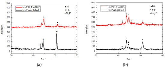
Figure 9.
X-ray diffraction (XRD) patterns of worn surfaces on Ni–P and annealed Ni–P coatings: (a) Ni–P wear region; (b) annealed Ni–P wear region.
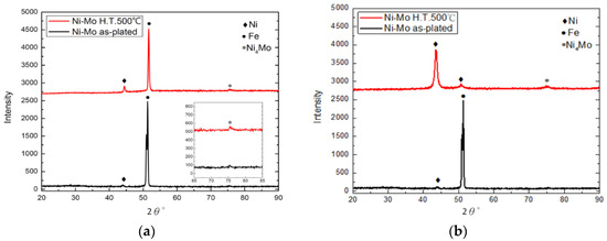
Figure 10.
XRD patterns of worn surfaces on Ni–Mo and annealed Ni–Mo coatings: (a) Ni–Mo wear region; (b) annealed Ni–Mo wear region.
The XRD patterns corresponding to nickel–molybdenum and annealed nickel–molybdenum-coated rail after the catapult test are provided in Figure 10. Figure 10a displays the XRD patterns from the light ablation region. As seen in Figure 10a, the intensity of the peak corresponding to iron is much higher than that of Ni for both Ni–Mo coating with and without heat treatment, indicating that more iron from the armature was melted by the current and transferred to the surface coating of rails during the sliding friction. Comparing the two XRD patterns in Figure 10a, it can be strongly suggested that more iron covered the surface of Ni–Mo coating than annealed Ni–Mo coating. However, the XRD patterns displayed in Figure 10b show that the intensity of peak corresponding to Ni crystal is higher than that of iron when the ablation is light for both Ni–Mo and annealed Ni–Mo coatings. Moreover, the Ni4Mo phase in the XRD profile can be seen at 2θ = 75° even for Ni–Mo coating without heat treatment. It has been reported that the precipitation of Ni4Mo initiates at a heat treatment temperature of 500 °C [24]. It is reasonable to think that most of the current passing through this ablation zone was used to heat the nickel–molybdenum coating to a temperature of 500 °C, and only a smaller part of heat was used to melt the armature. As a result, the obvious precipitation of the Ni4Mo phase is observed in the XRD patterns.
Through the above experimental analysis results, it can be clearly understood that part of the pulsed electrical energy released by the capacitor stack during the catapult experiment is consumed by the melting of the armature material, and the rest of the energy is used to propel the armature forward. The nickel–molybdenum and annealed nickel–molybdenum-coated rails used in this study have a higher melting point than nickel, iron, and phosphorus, resulting in the smallest area of electrical ablation on the surface of the rail. Although the armature catapult velocity is slightly reduced, the damaged area of the rail coated with annealed nickel–molybdenum is minimal. Reducing the surface roughness of the nickel–molybdenum coating will be an effective way to enhance the speed of armature ejection.
4. Conclusions
This study tested the rail surface materials of the electromagnetic rail catapult system, including five types of coatings—iron rail, nickel–phosphorus coating rail, nickel–phosphorus heat treatment coating rail, nickel–molybdenum coating rail and nickel–molybdenum heat treatment coating rail. This research obtained the following results:
- The hardness of these five tested materials is 215, 512, 650, 720 and 1045 HV for iron, nickel–phosphorus, annealed nickel–phosphorus, nickel–molybdenum, and annealed nickel–molybdenum, respectively. Heat treatment increases the hardness of the Ni–P and Ni–Mo coatings significantly, which can be ascribed to the precipitation of intermetallic compounds such as Ni3P precipitation for Ni–P and Ni4Mo precipitation for Ni–Mo coating.
- The contact resistance of the five rail-type materials is slightly higher than 0.2 Ω except for the annealed nickel–phosphorus-coated rail (0.186 Ω). However, its impact on the armature catapult velocity is not as obvious as the surface roughness of the rail. The sliding velocity of the armature decreases slightly with the increase in the surface roughness of the rail.
- During the catapult process, discontinuous and rapid electrical ablation on the rail surface was observed. The ratio of ablated area to the total area of these rails is: iron rail (19.5%) > Ni–P-coated rail (12.9%) > annealed Ni–P-coated rail (11.6%) > Ni–Mo-coated rail (4.9%) > annealed Ni–Mo-coated rail (1.1%). Our results show that the hardness of the rail material is an important factor for the resistance of electrical ablation.
- EDS analysis shows that there is more iron in the ablation area of nickel–phosphorus and annealed nickel–phosphorus-coated rails, indicating the iron from the armature material melted and transferred to nickel–phosphorus coating easily. On the contrary, the average value of iron in the ablation zone of annealed nickel–molybdenum coating is relatively small.
- XRD analysis of the ablation zone identifies the presence of Ni3P precipitation for nickel–phosphorus and annealed nickel–phosphorus-coated rails and Ni4Mo phase is observed for nickel–molybdenum and annealed nickel–molybdenum-coated rails. Therefore, it can be deduced that the rail surface of Ni–P and Ni–Mo systems can reach a high temperature that can induce the second phase precipitation. Most of the passing current is used for heating up the rail material and less energy can be used to melt the armature, resulting in a decrease in electrical ablation. Thus, the thermal conductivity should also be an important factor for the rail material to withstand the electrical ablation.
Author Contributions
Methodology, L.-S.H., P.-C.H., and C.-C.C.; investigation, L.-S.H., P.-C.H., and C.-C.C.; resources, K.-H.H. and M.-D.G.; writing—original draft preparation, L.-S.H.; writing—review and editing, P.-C.H., K.-H.H., and G.-L.W.; supervision, M.-D.G., and G.-L.W.; project administration, K.-H.H., M.-D.G., and G.-L.W. All authors have read and agreed to the published version of the manuscript.
Funding
This research was funded by Ministry of Science and Technology, Taiwan, Grant No. 108-2623-E-606 -004-D.
Acknowledgments
The supports of this work from MOST No. 108-2623-E-606-004-D is appreciated.
Conflicts of Interest
The authors declare no conflict of interest.
References
- Ma, W.; Lu, J. Thinking and study of electromagnetic launch technology. IEEE Trans. Plasma Sci. 2017, 45, 1071–1077. [Google Scholar] [CrossRef]
- Poltanov, A.; Jygailo, N.; Bykov, M.; Glinov, A.; Svobodov, A.; Belyakov, A.; Chernetskaya, N. Study of new materials for rail gun launchers. IEEE Trans. Magn. 1997, 33, 406–409. [Google Scholar] [CrossRef]
- An, S.; Kim, S.H.; Lee, Y.H.; Yang, K.S.; Jin, Y.S.; Kim, Y.B.; Kim, J.; Cho, C.; Yoon, S.H.; Koo, I.S. Operation of a 2.4-MJ Pulsed Power System for Rail gun. IEEE Trans. Plasma Sci. 2013, 42, 2886–2890. [Google Scholar]
- Andrianov, V.V.; Baev, V.P.; Kazantsev, N.A.; Ostashev, V.E.; Parizh, M.B.; Sheinkman, V.S. A Variable Inductor Circuit Design for Inductive Energy Storage Systems. Rev. Sci. Instrum. 1990, 61, 1537–1542. [Google Scholar] [CrossRef]
- Han, Y.; Lin, F.; Dai, L.; Zou, L.; Wang, L.; Liu, G.; Bo, L. Analysis of Electric Parameters of a PPS System and Their Influence on Muzzle Velocity in EMG. IEEE Trans. Magn. 2009, 45, 559–563. [Google Scholar]
- Stankevic, T.; Schneider, M.; Balevicius, S. Magnetic Diffusion inside the Rails of an Electromagnetic Launcher Experimental and Numerical Studies. IEEE Trans. Plasma Sci. 2013, 41, 2790–2795. [Google Scholar] [CrossRef]
- Tarcza, K.R.; Weldon, W.F. Metal Gouging at Low Relative Sliding Velocities. Wear 1997, 209, 21–30. [Google Scholar] [CrossRef]
- Aigner, S.; Igenbergs, E. Friction and Ablation Measurements in a Round Bore Rail Gun. IEEE Trans. Magn. 1989, 25, 33–39. [Google Scholar] [CrossRef]
- Persad, C.; Satapathy, S. Friction and Wear Sciences for a Highly Durable Rail Gun Weapon; Inst. Adv. Technol. Univ. Texas Austin: Austin, TX, USA, 2007; p. 512. [Google Scholar]
- Powell, J.; Zielinski, A. A Preliminary Study of Wear in the Solid-Armature Rail Gun; Inst. Adv. Technol. Univ. Texas Austin: Austin, TX, USA, 1997. [Google Scholar]
- Challita, A.; Chelluri, B.; Bauer, D.P. Minimizing Non-arcing Contact Material Deposition on Rails. IEEE Trans. Magn. 1995, 31, 134–137. [Google Scholar] [CrossRef]
- Colombo, G.R.; Otooni, M.; Evangelisti, M.P.; Colon, N.; Chu, E. Application of Coatings for Electromagnetic Gun Technology. IEEE Trans. Magn. 1995, 31, 704–708. [Google Scholar] [CrossRef]
- Siopis, M.J.; Neu, R.W. Materials Selection Exercise for Electromagnetic Launcher Rails. IEEE Trans. Magn. 2013, 49, 4831–4838. [Google Scholar] [CrossRef]
- Watt, T.; Motes, D.T. The Effect of Surface Coating on the Onset of Rail Gouging. IEEE Trans. Plasma Sci. 2011, 39, 168–173. [Google Scholar] [CrossRef]
- McNeal, C.J. Barrel Wear Reduction in Rail Guns: The Effects of Known and Controlled Rail Spacing on Low Voltage Electrical Contact and the Hard Chrome Plating of Copper-Tungsten Rail and Pure Copper Rails. Master’s Thesis, Naval Postgraduate School, Monterey, CA, USA, 2003. [Google Scholar]
- Fayyad, P.M.; Abdullah, A.M.; Hassan, M.K.; Mohamed, A.M.; Jarjoura, G.; Farhat, Z. Recent advances in electroless-plated Ni-P and its composites for erosion and corrosion applications: A review. Emergent Mater. 2018, 1, 3–24. [Google Scholar] [CrossRef]
- Zhang, H.; Zou, J.; Lin, N.; Tang, B. Review on electroless plating Ni–P coatings for improving surface performance of steel. Surf. Rev. Lett. 2014, 21, 1430002. [Google Scholar] [CrossRef]
- Lima-Neto, P.; Correia, A.N.; Vaz, G.L.; Casciano, P.N.S. Morphological, Structural, Microhardness and Corrosion Characterisations of Electrodeposited Ni–Mo and Cr Coatings. J. Braz. Chem. Soc. 2010, 21, 1968–1976. [Google Scholar] [CrossRef]
- Sanches, L.S.; Domingues, S.H.; Marino, C.E.B.; Mascaro, L.H. Characterisation of electrochemically deposited Ni–Mo alloy coatings. Electrochem. Commun. 2004, 6, 543–548. [Google Scholar] [CrossRef]
- Ma, C.; Wang, S.C.; Wang, L.P.; Walsh, F.C.; Woo, R.J. The electrodeposition and characterization of low-friction and wear-resistant Co–Ni–P coatings. Surf. Coat. Technol. 2013, 235, 495–505. [Google Scholar] [CrossRef]
- Chassaing, E.; Quang, K.V.; Wiart, R. Mechanism of Ni–Mo alloy electro deposition in citrate electrolytes. J. Appl. Electrochem. 1989, 19, 839–844. [Google Scholar] [CrossRef]
- Hou, K.H.; Jeng, M.C.; Ger, M.-D. A Study on the wear resistance characteristics of pulse electro forming Ni–P alloy coatings as plated. Wear 2007, 262, 833–844. [Google Scholar] [CrossRef]
- Hou, K.H.; Jeng, M.C.; Ger, M.D. The Heat Treatment Effects on the Structure and Wear Behavior of Pulse Electroforming Ni–P Alloy Coatings. J. Alloys Compd. 2007, 437, 289–297. [Google Scholar] [CrossRef]
- Huang, P.C.; Hou, K.H.; Sheu, H.H.; Ger, M.D.; Wang, G.L. Wear Properties of Ni–Mo Coatings Produced by Pulse Electroforming. Surf. Coat. Technol. 2014, 258, 639–645. [Google Scholar] [CrossRef]
- Huang, P.C.; Hou, K.H.; Wang, G.L.; Chen, M.L.; Wang, J.R. Corrosion Resistance of the Ni–Mo Alloy Coatings Related to Coating’s Electroplating Parameters. Int. J. Electrochem. Sci. 2015, 10, 4972–4984. [Google Scholar]
- Zhou, Y.; Yan, P.; Sun, Y.H.; Wang, J.; Li, M.T. A Simple Model of high-power thyristor and its application in Eml transient analysis. In Proceedings of the PPC 2009: IEEE Pulsed Power Conference, Washington, DC, USA, 28 June–2 July 2009; pp. 1299–1302. [Google Scholar]
- Zhou, Y.; Yan, P.; Sun, Y.; Zhang, D.; Li, M. Analysis on efficiency improvement with a distributed energy store rail gun. In Proceedings of the 2010 IEEE International Power Modulator and High Voltage Conference, Atlanta, GA, USA, 23–27 May 2010; pp. 587–589. [Google Scholar]
- Hoffman, D.J.; Borraccini, J.P.; Swindler, S.B.; Petersen, L.J. Next Generation Power and Energy: Maybe Not So Next Generation. Naval Eng. J. 2010, 122, 59–74. [Google Scholar]
- Dong, J.; Zhang, J.; Li, J.; Gui, Y.; Cui, Y.; Li, S.; Su, N. The 100 Kj modular pulsed power units for rail gun. IEEE Trans. Plasma Sci. 2011, 39, 275–278. [Google Scholar] [CrossRef]
- Liu, P.; Yu, X.; Li, J.; Li, S. Study on energy conversion efficiency of EM launcher with a capacitor based pulsed power system. IEEE Trans. Plasma Sci. 2013, 419, 1–4. [Google Scholar]
- Gao, J.; Liu, L.; Wu, Y.; Shen, B.; Hu, W. Electroless Ni–P–SiC composite coatings with superfine particles. Surf. Coat. Technol. 2006, 200, 5836–5842. [Google Scholar]
- Seo, M.H.; Kim, J.S.; Hwang, W.S.; Kim, D.J.; Hwang, S.S.; Chun, B.S. Characteristics of Ni–P alloy electrodeposited from a sulfamate bath. Surf. Coat. Technol. 2004, 176, 135–140. [Google Scholar] [CrossRef]
- Archard, J.F. Contact and Rubbing of Flat Surfaces. J. Appl. Phys. 1953, 24, 981–988. [Google Scholar] [CrossRef]
- Duncan, R.N. The metallurgical structure of electroless nickel deposits: Effect on coating properties. Plat. Surf. Finish. 1996, 83, 65–69. [Google Scholar]
Publisher’s Note: MDPI stays neutral with regard to jurisdictional claims in published maps and institutional affiliations. |
© 2020 by the authors. Licensee MDPI, Basel, Switzerland. This article is an open access article distributed under the terms and conditions of the Creative Commons Attribution (CC BY) license (http://creativecommons.org/licenses/by/4.0/).