Spin Coating Immobilisation of C-N-TiO2 Co-Doped Nano Catalyst on Glass and Application for Photocatalysis or as Electron Transporting Layer for Perovskite Solar Cells


 ,
,  , ,
, , .jpg) ,
,  ,
,  , and
, and
Abstract
1. Introduction
2. Materials and Methods
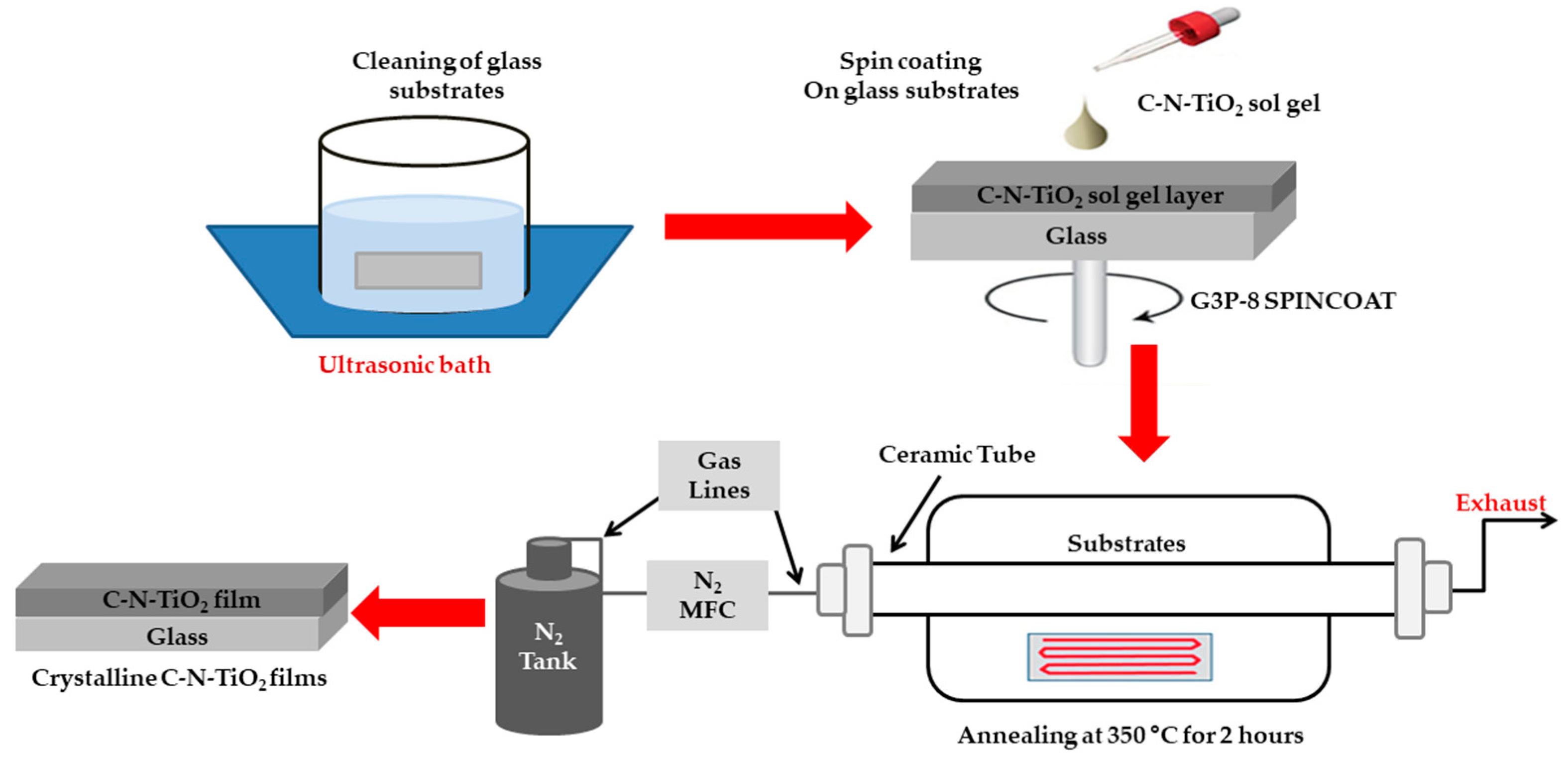
2.1. Preparation of C-N-TiO2 Sol-Gel
2.2. C-N-TiO2 Film Procedure
2.3. Effect of Spin Coating Speed and Sol-Gel Dilution on the Thickness of Thin Films
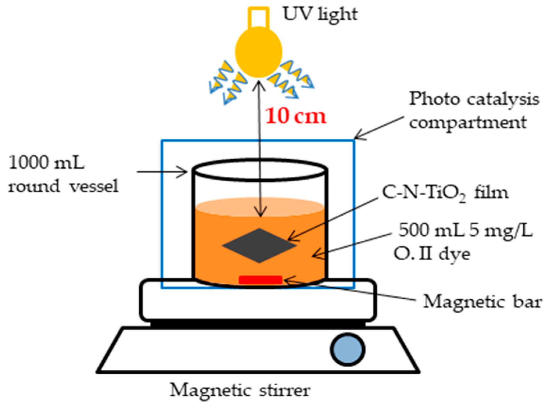
2.4. Application 1: Photo Catalysis Test
2.5. Perovskite Solar Cells Fabrication
2.6. Application 2: Perovskite Solar Cells
3. Results
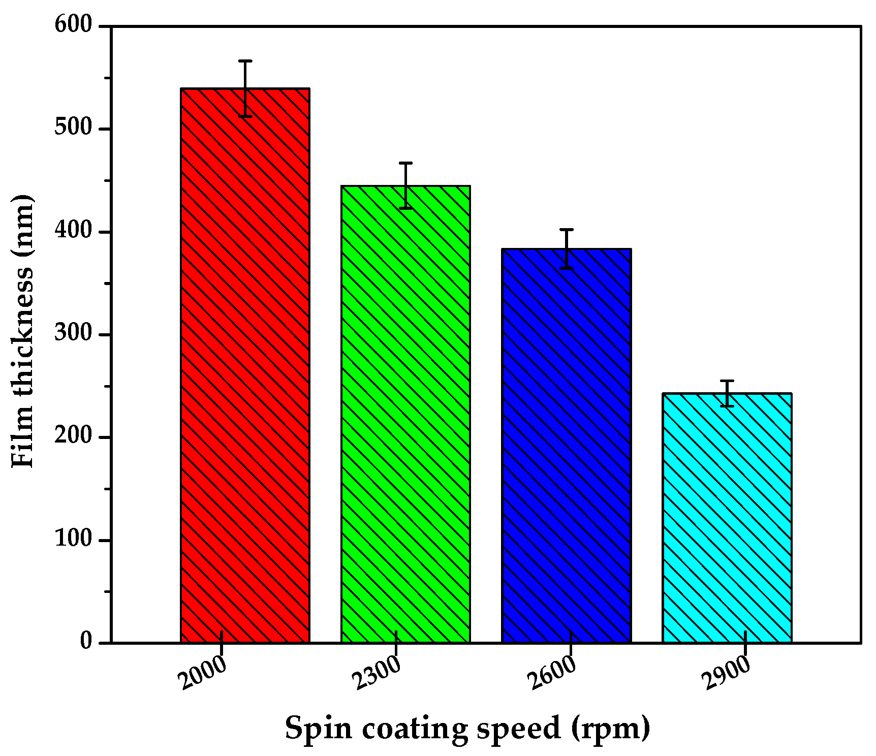
3.1. Effect of Spin Coating Speed on the Thickness of C-N-TiO2 Thin Films
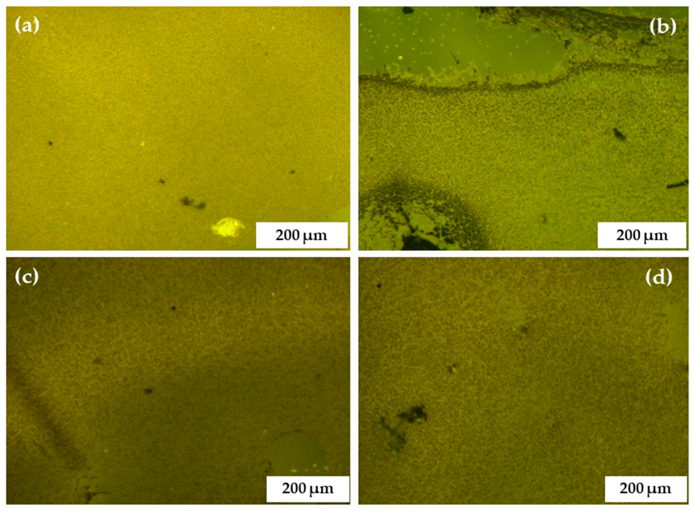
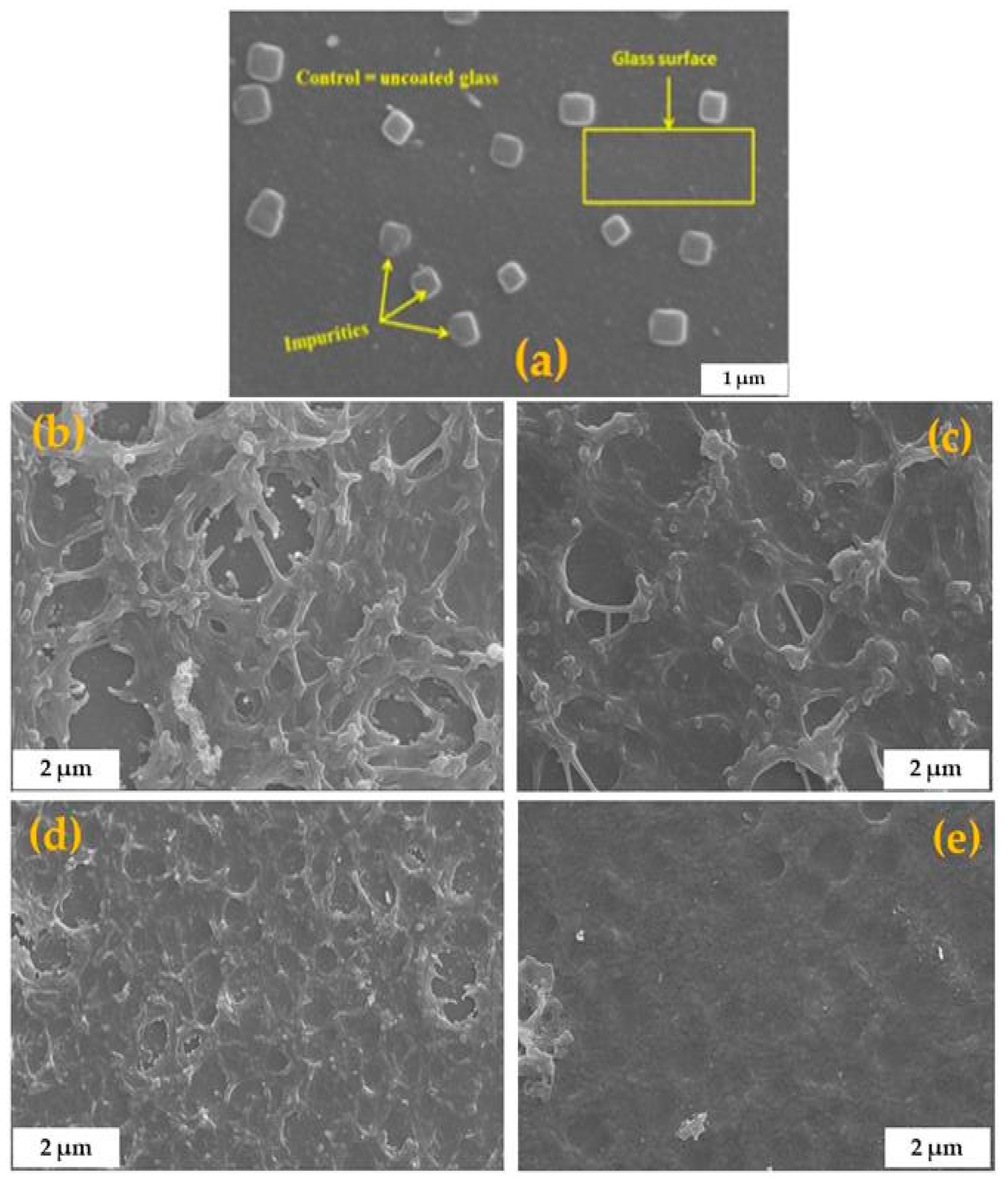
3.2. Light Microscopy, Scanning Electron Microscopy, and Energy Dispersive Spectroscopy
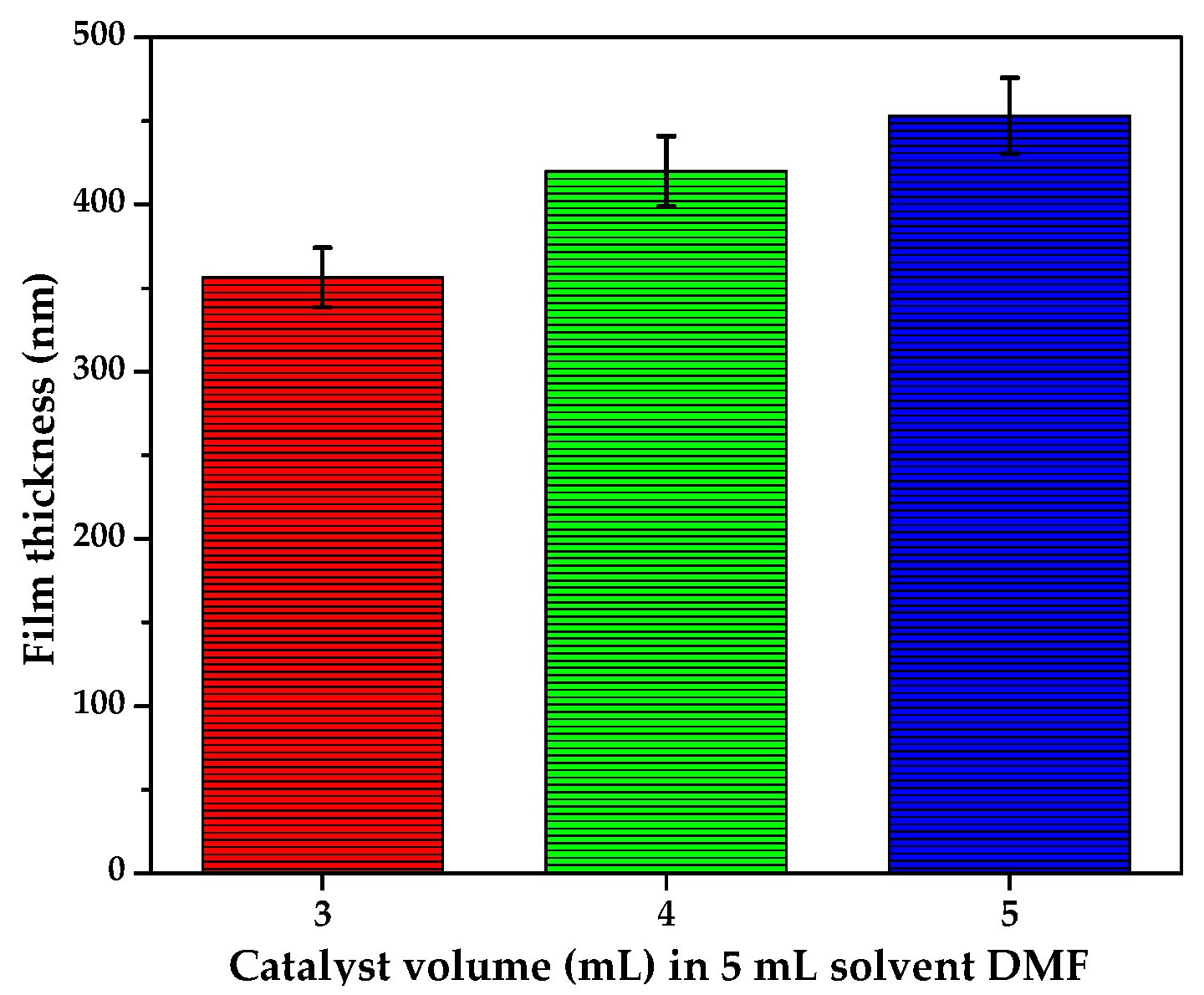
3.3. Effect of Sol Gel–Solvent Ratio on the Thickness of Thin Films
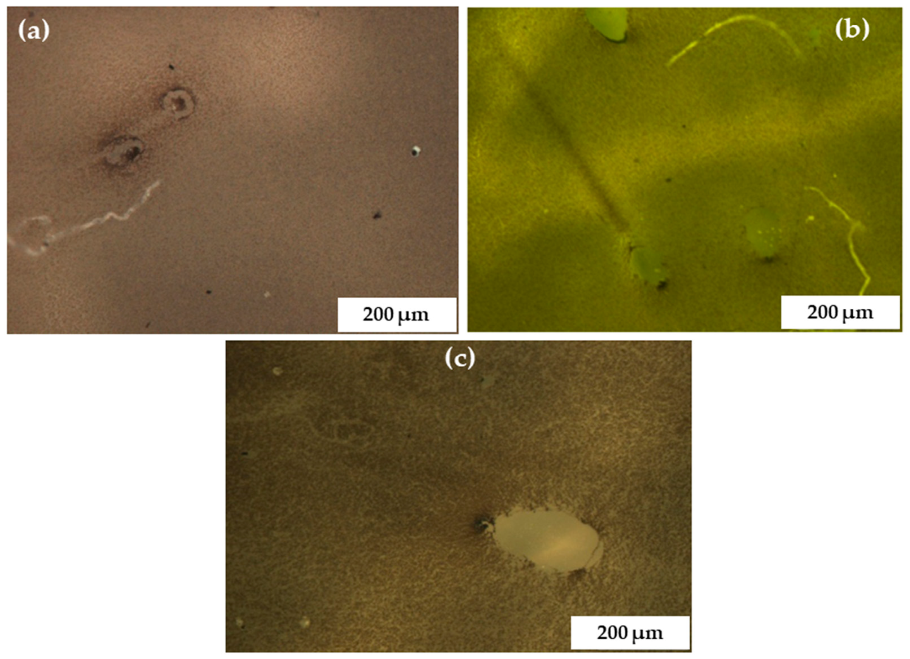
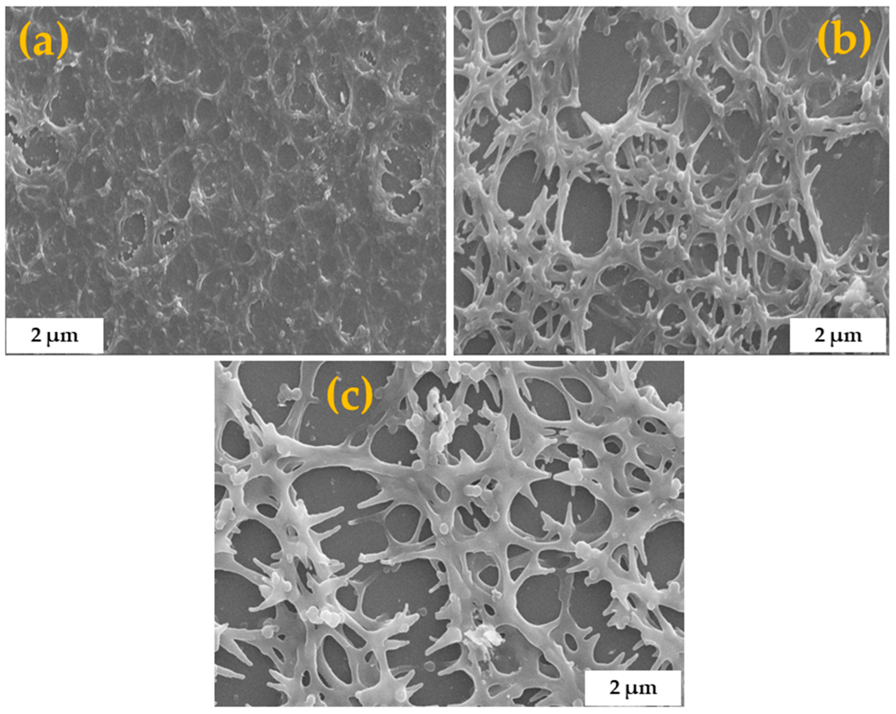
3.4. Light Microscopy, Scanning Electron Microscopy, and Energy Dispersive Spectroscopy
3.5. Application 1: Photo Catalysis Tests
3.5.1. Effect of Spin Coating Speed on the Degradation of Orange II Sodium Salt Dye
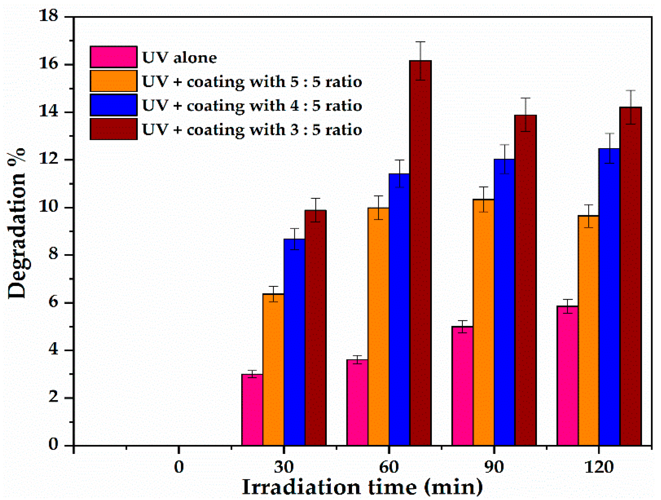
3.5.2. Effect of Sol Gel to Solvent Ratio on the Photocatalytic Activity of Coated Glass on Orange II Dye Removal
3.6. Application 2: Perovskite Solar Cells
Replacement of mTiO2 by C-N-TiO2
4. Discussion
5. Conclusions
6. Novelty
Author Contributions
Funding
Acknowledgments
Conflicts of Interest
References
- Trovó, A.G.; Nogueira, R.F.; Agüera, A.; Fernandez-Alba, A.R.; Sirtori, C.; Malato, S. Degradation of sulfamethoxazole in water by solar photo-Fenton. Chemical and toxicological evaluation. Water Res. 2009, 43, 3922–3931. [Google Scholar] [CrossRef] [PubMed]
- Magureanu, M.; Piroi, D.; Mandache, N.B.; David, V.; Medvedovici, A.; Parvulescu, V.I. Degradation of pharmaceutical compound pentoxifylline in water by non-thermal plasma treatment. Water Res. 2010, 44, 3445–3453. [Google Scholar] [CrossRef] [PubMed]
- Klavarioti, M.; Mantzavinos, D.; Kassinos, D. Removal of residual pharmaceuticals from aqueous systems by advanced oxidation processes. Environ. Int. 2009, 35, 402–417. [Google Scholar] [CrossRef] [PubMed]
- Haber, F.; Weiss, J. The catalytic decomposition of hydrogen peroxide by iron salts. Proc. R. Soc. Lond. 1934, 147, 332–351. [Google Scholar] [CrossRef]
- Stasinakis, A.S. Use of selected advanced oxidation processes (aops) for wastewater treatment-a mini review. Glob. NEST J. 2008, 10, 376–385. [Google Scholar]
- Bankole, M.T.; Tijani, J.O.; Mohammed, I.A.; AbdulKareem, A.S. A review on nanotechnology as a tool of change in Nigeria. Sci. Res. Essays 2014, 9, 213–223. [Google Scholar]
- Loures, C.C.; Alcântara, M.A.; Izário Filho, H.J.; Teixeira, A.C.; Silva, F.T.; Paiva, T.C.; Samanamud, G.R. Advanced Oxidative Degradation Processes: Fundamentals and Applications. Int. Rev. Chem. Eng. 2013, 5, 102–120. [Google Scholar] [CrossRef]
- Gupta, S.B. Investigation of a Physical Disinfection Process Based on Pulsed Underwater Corona Discharges. Ph.D. Thesis, Forschungszentrum Karlshrue, Karlsruhe, Germany, 2007. [Google Scholar]
- Esplugas, S.; Bila, D.M.; Krause, L.G.T.; Dezotti, M. Ozonation and advanced oxidation technologies to remove endocrine disrupting chemicals (EDCs) and pharmaceuticals and personal care products (PPCPs) in water effluents. J. Hazard. Mater. 2007, 149, 631–642. [Google Scholar] [CrossRef]
- Iqbal, M.; Bhatti, I.A.; Ahmad, I. Photo-degradation of the methyl blue: Optimization through response surface methodology using rotatable center composite design. Int. J. Basic Appl. Sci. 2013, 2, 145. [Google Scholar] [CrossRef][Green Version]
- Rizzo, L.; Meric, S.; Guida, M.; Kassinos, D.; Belgiorno, V. Heterogenous photocatalytic degradation kinetics and detoxification of an urban wastewater treatment plant effluent contaminated with pharmaceuticals. Water Res. 2009, 43, 4070–4078. [Google Scholar] [CrossRef]
- Soresa, M. Ayka Addis Textile Wastewater Treatment by the Fenton’s Reagent. Addis Ababa University Institute of Technology School of Graduate Studies, Department of Chemical and Engineering, A Thesis Submitted to the Graduate Studies of Addis Ababa University, in Partial Fulfillment of the Degree of Master of Science in Chemical Engineering (Process Engineering). 2011. Available online: http://localhost:80/xmlui/handle/123456789/8575 (accessed on 1 June 2011).
- Lin, Y.T.; Weng, C.H.; Chen, F.Y. Key operating parameters affecting photocatalytic activity of visible-light-induced C-doped TiO2 catalyst for ethylene oxidation. Chem. Eng. J. 2014, 248, 175–183. [Google Scholar] [CrossRef]
- Lazar, M.A.; Varghese, S.; Nair, S.S. Photocatalytic Water Treatment by Titanium Dioxide: Recent Updates. Catalysts 2012, 2, 572–601. [Google Scholar] [CrossRef]
- Klaysri, R.; Ratova, M.; Praserthdam, P.; Kelly, P. Deposition of Visible Light-Active C-Doped Titania Films via Magnetron Sputtering Using CO2 as a Source of Carbon. Nanomaterials 2017, 7, 113. [Google Scholar] [CrossRef]
- Schäffer, J. Immobilization of TiO2 Via Different Routes for Photocatalytic Reactions in a PDMS Based Microreactor. Bachelor’s Thesis, University of Twente, Enschede, The Netherlands, 2012. Available online: http://purl.utwente.nl/essays/62126 (accessed on 1 August 2012).
- Lindstrom, H.; Wootton, R.; Iles, A. High surface area titania photocatalytic microfluidic reactors. AIChE J. 2007, 53, 695–702. [Google Scholar] [CrossRef]
- Shan, A.Y.; Ghazi, T.I.; Rashid, S.A. Immobilisation of titanium dioxide onto supporting materials in heterogeneous photocatalysis: A review. Appl. Catal. A Gen. 2010, 389, 1–8. [Google Scholar] [CrossRef]
- Brinker, C.J.; Scherer, G.W. Solgel Science: The Physics and Chemistry of Solgel Processing; Academic Press Inc.: Cambridge, MA, USA, 1990; ISBN 0-12-134970-5. [Google Scholar]
- Mechiakh, R.; Sedrine, N.B.; Chtourou, R.; Bensaha, R. Correlation between microstructure and optical properties of nano-crystalline TiO2 thin films prepared by sol-gel dip coating. Appl. Surf. Sci. 2010, 15, 670–676. [Google Scholar] [CrossRef]
- Avci, N.; Smet, P.F.; Poelman, H.; Van de Velde, N.; De Buysser, K.; Van Driessche, I.; Poelman, D. Characterization of TiO2 powders and thin films prepared by non-aqueous sol-gel techniques. J. SolGel Sci. Technol. 2009, 52, 424–431. [Google Scholar] [CrossRef]
- Calderon-Moreno, J.M.; Preda, S.; Predoana, L.; Zaharescu, M.; Anastasescu, M.; Nicolescu, M.; Stoica, M.; Stroescu, H.; Gartner, M.; Buiu, O.; et al. Effect of polyethylene glycol on porous transparent TiO2 films prepared by sol-gel method. Ceram. Int. 2014, 40, 2209–2220. [Google Scholar] [CrossRef]
- Aksoy, S.; Caglar, Y. Structural transformations of TiO2 films with deposition temperature and electrical properties of nanostructure n-TiO2/p-Si heterojunction diode. J. Alloy. Compd. 2014, 613, 330–337. [Google Scholar] [CrossRef]
- Kumar, A.; Mondal, S.; Kumar, S.G.; Rao, K.K. High performance sol-gel spin-coated titanium dioxide dielectric based MOS structures. Mater. Sci. Semicond. Process. 2015, 40, 77–83. [Google Scholar] [CrossRef]
- Shu, H.; Yang, M.; Liu, Q.; Luo, M. Study of TiO2-Modified Sol Coating Material in the Protection of Stone-Built Cultural Heritage. Coatings 2020, 10, 179. [Google Scholar] [CrossRef]
- Molkenova, A.; Khamkhash, L.; Zhussupbekova, A.; Zhussupbekov, K.; Sarsenov, S.; Taniguchi, I.; Shvets, I.V.; Atabaev, T.S. Solution-Based Deposition of Transparent Eu-Doped Titanium Oxide Thin Films for Potential Security Labeling and UV Screening. Nanomaterials 2020, 10, 1132. [Google Scholar] [CrossRef]
- Saliba, M.; Matsui, T.; Seo, J.Y.; Domanski, K.; Correa-Baena, J.P.; Nazeeruddin, M.K.; Zakeeruddin, S.M.; Tress, W.; Abate, A.; Hagfeldt, A.; et al. Cesium-containing triple cation perovskite solar cells: Improved stability, reproducibility and high efficiency. Energy Environ. Sci. 2016, 9, 1989–1997. [Google Scholar] [CrossRef] [PubMed]
- Polyakov, A.Y.; Smirnov, N.B.; Shchemerov, I.V.; Saranin, D.S.; Le, T.S.; Didenko, S.I.; Kuznetsov, D.V.; Agresti, A.; Pescetelli, S.; Matteocci, F.; et al. Trap states in multication mesoscopic perovskite solar cells: A deep levels transient spectroscopy investigation. Appl. Phys. Lett. 2018, 113, 263501. [Google Scholar] [CrossRef]
- Agresti, A.; Pescetelli, S.; Najafi, L.; Castillo, A.D.; Oropesa-Nuñez, R.; Busby, Y.; Bonaccorso, F.; Di Carlo, A. Graphene and related 2D materials for high efficient and stable perovskite solar cells. In Proceedings of the IEEE 17th International Conference on Nanotechnology (IEEE-NANO), Pittsburgh, PA, USA, 25–28 July 2017; pp. 145–150. [Google Scholar] [CrossRef]
- Agresti, A.; Cinà, L.; Pescetelli, S.; Taheri, B.; Di Carlo, A. Stability of dye-sensitized solar cell under reverse bias condition: Resonance Raman spectroscopy combined with spectrally resolved analysis by transmittance and efficiency mapping. Vib. Spectrosc. 2016, 84, 106–117. [Google Scholar] [CrossRef]
- Busby, Y.; Agresti, A.; Pescetelli, S.; Di Carlo, A.; Noel, C.; Pireaux, J.J.; Houssiau, L. Aging effects in interface-engineered perovskite solar cells with 2D nanomaterials: A depth profile analysis. Mater. Today Energy 2018, 9, 1–10. [Google Scholar] [CrossRef]
- Zhuang, J.; Dai, W.; Tian, Q.; Li, Z.; Xie, L.; Wang, J.; Liu, P.; Shi, X.; Wang, D. Photocatalytic degradation of RhB over TiO2 bilayer films: Effect of defects and their location. Langmuir 2010, 26, 9686–9694. [Google Scholar] [CrossRef]
- Chen, Y.; Stathatos, E.; Dionysiou, D.D. Microstructure characterization and photocatalytic activity of mesoporous TiO2 films with ultrafine anatase nanocrystallites. Surf. Coat. Technol. 2008, 202, 1944–1950. [Google Scholar] [CrossRef]
- Pelaez, M.; Falaras, P.; Likodimos, V.; Kontos, A.G.; Armah, A.; O’shea, K.; Dionysiou, D.D. Synthesis, structural characterization and evaluation of sol-gel-based NF-TiO2 films with visible light-photoactivation for the removal of microcystin-LR. Appl. Catal. B Environ. 2010, 99, 378–387. [Google Scholar] [CrossRef]
- Han, C.; Pelaez, M.; Likodimos, V.; Kontos, A.G.; Falaras, P.; O’Shea, K.; Dionysiou, D.D. Innovative visible light-activated sulfur doped TiO2 films for water treatment. Appl. Catal. B Environ. 2011, 107, 77–87. [Google Scholar] [CrossRef]
- Lu, P.J.; Chien, C.W.; Chen, T.S.; Chern, J.M. Azo dye degradation kinetics in TiO2film-coated photoreactor. Chem. Eng. J. 2010, 163, 28–34. [Google Scholar] [CrossRef]
- Kenanakis, G.; Vernardou, D.; Dalamagkas, A.; Katsarakis, N. Photocatalytic and electrooxidation properties of TiO2 thin films deposited by sol-gel. Catalysis Today 2015, 240 Pt A, 146–152. [Google Scholar] [CrossRef]
- Zabihi, F.; Xie, Y.; Gao, S.; Eslamian, M. Morphology, conductivity, and wetting characteristics of PEDOT: PSS thin films deposited by spin and spray coating. Appl. Surf. Sci. 2015, 338, 163–177. [Google Scholar] [CrossRef]
- Clausi, M.; Santonicola, M.G.; Laurenzi, S. Fabrication of carbon-based nanocomposite films by spin-coating process: An experimental and modeling study of the film thickness. Compos. Part A Appl. Sci. Manuf. 2016, 88, 86–97. [Google Scholar] [CrossRef]
- Guillard, C.; Lachheb, H.; Houas, A.; Ksibi, M.; Elaloui, E.; Herrmann, J.M. Influence of chemical structure of dyes, of pH and of inorganic salts on their photocatalytic degradation by TiO2 comparison of the efficiency of powder and supported TiO2. J. Photochem. Photobiol. A Chem. 2003, 158, 27–36. [Google Scholar] [CrossRef]
- Danish, M.; Ambreen, S.; Chauhan, A.; Pandey, A. Optimization and comparative evaluation of optical and photocatalytic properties of TiO2 thin films prepared via sol-gel method. J. Saudi Chem. Soc. 2015, 19, 557–562. [Google Scholar] [CrossRef]
- Dijkstra, M.F.; Panneman, H.J.; Winkelman, J.G.; Kelly, J.J.; Beenackers, A.A. Modeling the photocatalytic degradation of formic acid in a reactor with immobilized catalyst. Chem. Eng. Sci. 2002, 57, 4895–4907. [Google Scholar] [CrossRef]
- Rajendran, K.; Kumar, V.S.; Rani, K.A. Synthesis and characterization of immobilized activated carbon doped TiO2 thin films. Optik Stuttgarter 2014, 125, 1993–1996. [Google Scholar] [CrossRef]
- Varshney, G.; Kanel, S.R.; Kempisty, D.M.; Varshney, V.; Agrawal, A.; Sahle-Demessie, E.; Varma, R.S.; Nadagouda, M.N. Nanoscale TiO2 films and their application in remediation of organic pollutants. Coord. Chem. Rev. 2016, 306 Pt 1, 43–64. [Google Scholar] [CrossRef]
- Arabatzis, I.M.; Antonaraki, S.; Stergiopoulos, T.; Hiskia, A.; Papaconstantinou, E.; Bernard, M.C.; Falaras, P. Preparation, characterization and photocatalytic activity of nanocrystalline thin film TiO2 catalysts towards 3,5-dichlorophenol degradation. J. Photochem. Photobiol. A Chem. 2002, 149, 237–245. [Google Scholar] [CrossRef]
- Jarka, P.; Tański, T.; Matysiak, W.; Krzemiński, Ł.; Hajduk, B.; Bilewicz, M. Manufacturing and investigation of surface morphology and optical properties of composite thin films reinforced by TiO2, Bi2O3 and SiO2 nanoparticles. Appl. Surf. Sci. 2017, 424 Pt 2, 206–212. [Google Scholar] [CrossRef]
- Agresti, A.; Pescetelli, S.; Palma, A.L.; Martín-García, B.; Najafi, L.; Bellani, S.; Moreels, I.; Prato, M.; Bonaccorso, F.; Di Carlo, A. Two-dimensional (2D) Material Interface Engineering for Efficient Perovskite Large-area Modules. ACS Energy Lett. 2019, 4, 1862–1871. [Google Scholar] [CrossRef]
- Palma, A.L.; Matteocci, F.; Agresti, A.; Pescetelli, S.; Calabrò, E.; Vesce, L.; Christiansen, S.; Schmidt, M.; Di Carlo, A. Laser-Patterning Engineering for Perovskite Solar Modules with 95% Aperture Ratio. IEEE J. Photovolt. 2017, 7, 1674–1680. [Google Scholar] [CrossRef]
- Zanotti, G.; Angelini, N.; Mattioli, G.; Paoletti, A.M.; Pennesi, G.; Caschera, D.; Sobolev, A.P.; Beverina, L.; Calascibetta, A.M.; Sanzone, A.; et al. [1]Benzothieno[3,2-b][1]benzothiophene-Phthalocyanine Derivatives: A Subclass of Solution-Processable Electron-Rich Hole Transport Materials. ChemPlusChem 2020. [Google Scholar] [CrossRef]
- Agresti, A.; Pescetelli, S.; Palma, A.L.; Del Rio Castillo, A.E.; Konios, D.; Kakavelakis, G.; Razza, S.; Cinà, L.; Kymakis, E.; Bonaccorso, F.; et al. Graphene Interface Engineering for Perovskite Solar Module: A Power Conversion Efficiency Exceeding 12.5% over 50 cm2 Active Area. ACS Energy Lett. 2017, 2, 279–287. [Google Scholar] [CrossRef]
- Taheri, B.; Nia, N.Y.; Agresti, A.; Pescetelli, S.; Ciceroni, C.; Castillo, A.E.; Cinà, L.; Bellani, S.; Bonaccorso, F.; Di Carlo, A. Graphene-engineered automated sprayed mesoscopic structure for perovskite device scaling-up. 2D Mater. 2018, 5, 045034. [Google Scholar] [CrossRef]
- O’keeffe, P.; Catone, D.; Paladini, A.; Toschi, F.; Turchini, S.; Avaldi, L.; Martelli, F.; Agresti, A.; Pescetelli, S.; Del Rio Castillo, A.E.; et al. Supporting information graphene-induced improvements of perovskite solar cell stability: Effects on hot-carriers. Nano Lett. 2019, 19, 684–691. [Google Scholar] [CrossRef]
- Agresti, A.; Pazniak, A.; Pescetelli, S.; Di Vito, A.; Rossi, D.; Pecchia, A.; der Maur, M.A.; Liedl, A.; Larciprete, R.; Kuznetsov, D.V.; et al. Titanium-carbide MXenes for work function and interface engineering in perovskite solar cells. Nat. Mater. 2019, 18, 1228–1234. Available online: www.nature.com/naturematerials (accessed on 14 October 2019). [CrossRef]
- Najafi, L.; Taheri, B.; Martín-García, B.; Bellani, S.; Di Girolamo, D.; Agresti, A.; Oropesa-Nunez, R.; Pescetelli, S.; Vesce, L.; Calabro, E.; et al. MoS2 Quantum Dot/Graphene Hybrids for Advanced Interface Engineering of CH3NH3 PbI3 Perovskite Solar Cell with Efficiency over 20%. ACS Nano 2018, 12, 10736–10754. [Google Scholar] [CrossRef]
- Wu, C.-Y.; Lee, Y.-L.; Lo, Y.-S.; Lin, C.-J.; Wu, C.-H. Thickness-dependent photocatalytic performance of nanocrystalline TiO2 thin films prepared by sol–gel spin coating. Appl. Surf. Sci. 2013, 280, 737–744. [Google Scholar] [CrossRef]
- Lin, H.-J.; Yang, T.-S.; Hsi, C.-S.; Wang, M.-C.; Lee, K.-C. Optical and photocatalytic properties of Fe3+-doped TiO2 thin films prepared by a sol–gel spin coating. Ceram. Int. 2014, 40, 10633–10640. [Google Scholar] [CrossRef]
- Bsiri, N.; Zrir, M.A.; Bardaoui, A.; Bouaїcha, M. Morphological, structural and ellipsometric investigations of Cr doped TiO2 thin films prepared by sol–gel and spin coating. Ceram. Int. 2016, 42, 10599–10607. [Google Scholar] [CrossRef]
- Bamoulid, L.; Benoit-Marquié, F.; Aries, L.; Guenbour, A.; Bachir, A.B.; Maurette, M.T.; Ansart, F.; El Hajjaji, S. Investigations on composition and morphology of electrochemical conversion layer/titanium dioxide deposit on stainless steel. Surf. Coat. Technol. 2006, 201, 2791–2795. [Google Scholar] [CrossRef]
- Chen, Y.; Dionysiou, D.D. Cor relation of structural properties and film thickness to photocatalytic activity of thick TiO2 films coated on stainless steel. Appl. Catal. B: Environ. 2006, 69, 24–33. [Google Scholar] [CrossRef]
- Khanna, S.; Marathey, P.; Chaliyawala, H.; Rajaram, N.; Roy, D.; Banerjee, R.; Mukhopadhyay, I. Fabrication of long-ranged close-packed monolayer of silica nanospheres by spin coating. Colloids Surf. A 2018, 553, 520–527. [Google Scholar] [CrossRef]
- Wang, Q.; Juarez-Perez, E.J.; Jiang, S.; Qiu, L.; Ono, L.K.; Sasaki, T.; Wang, X.; Shi, Y.; Zheng, Y.; Qi, Y.; et al. Spin-Coated Crystalline Molecular Monolayers for Performance Enhancement in Organic Field-Effect Transistors. J. Phys. Chem. Lett. 2018, 9, 1318–1323. [Google Scholar] [CrossRef] [PubMed]
- Wang, H.; Wang, Y.; Chen, X. Synthesis of uniform silver nanowires from AgCl seeds for transparent conductive films via spin-coating at variable spin-speed. Colloids Surf. A 2019, 565, 154–161. [Google Scholar] [CrossRef]
- Gültekin, A.; Karanfil, G.; Özel, F.; Kuş, M.; Say, R.; Sönmezoğlu, S. Synthesis and characterisations of Au-nanoparticle-doped TiO2 and CdO thin films. J. Phys. Chem. Solids 2014, 75, 775–781. [Google Scholar] [CrossRef]
- Manley, E.F.; Strzalka, J.; Fauvell, T.J.; Jackson, N.E.; Leonardi, M.J.; Eastham, N.D.; Marks, T.J.; Chen, L.X. In Situ GIWAXS Analysis of Solvent and Additive Effects on PTB7 Thin Film Microstructure Evolution during Spin Coating. Adv. Mater. 2017, 29, 1703933. [Google Scholar] [CrossRef]
- Chen, J.; Zhang, L.; Jiang, X.; Gao, K.; Liu, F.; Gong, X.; Chen, J.; Cao, Y. Using o-Chlorobenzaldehyde as a Fast Removable Solvent Additive during Spin-Coating PTB7-Based Active Layers: High Efficiency Thick-Film Polymer Solar Cells. Adv. Energy Mater. 2016, 7, 1601344. [Google Scholar] [CrossRef]
- Wang, Q.; Zheng, X.; Deng, Y.; Zhao, J.; Chen, Z.; Huang, J. Stabilizing the α-Phase of CsPbI3 Perovskite by Sulfobetaine Zwitterions in One-Step Spin-Coating Films. Joule 2017, 1, 371–382. [Google Scholar] [CrossRef]
- Deora, M.S.; Sharma, S.K. Effect of incorporation of sulphur on the structural, morphological and optical studies of CdSe thin films deposited by solution processed spin coating technique. Thin Solid Film. 2019, 670, 68–75. [Google Scholar] [CrossRef]
- Gültekin, A.; Karanfil, G.; Özel, F.; Kuş, M.; Say, R.; Sönmezoğlu, S. The influence of CdS quantum dots incorporation on the properties of CdO thin films. Eur. Phys. J. Appl. Phys. 2013, 64, 30303. [Google Scholar] [CrossRef]
- Pérez, J.B.; Courel, M.; Pal, M.; Delgado, F.P.; Mathews, N.R. Effect of ytterbium doping concentration on structural, optical and photocatalytic properties of TiO2 thin films. Ceram. Int. 2017, 43, 15777–15784. [Google Scholar] [CrossRef]
- Hassan, M.E.; Cong, L.; Liu, G.; Zhu, D.; Cai, J. Synthesis and characterization of C-doped TiO2 thin films for visible-light-induced photocatalytic degradation of methyl orange. Appl. Surf. Sci. 2014, 294, 89–94. [Google Scholar] [CrossRef]
- Massima Mouele, E.S.; Tijani, J.; Masikini, M.; Fatoba, O.; Eze, C.P.; Onwordi, C.T.; Zar Myint, M.T.; Kyaw, H.H.; Al-Sabahi, J.; Al-Abri, M.; et al. Spectroscopic Measurements of Dissolved O3, H2O2 and OH Radicals in Double Cylindrical Dielectric Barrier Discharge Technology: Treatment of Methylene Blue Dye Simulated Wastewater. Plasma 2020, 3, 59–91. [Google Scholar] [CrossRef]
- Boro, B.; Gogoi, B.; Rajbongshi, B.M.; Ramchiary, A. Nano-structured TiO2/ZnO nanocomposite for dye-sensitized solar cells application: A review. Renew. Sustain. Energy Rev. 2018, 81, 2264–2270. [Google Scholar] [CrossRef]
- Gupta, A.; Sahu, K.; Dhonde, M.; Murty, V.V. Novel synergistic combination of Cu/S co-doped TiO2 nanoparticles incorporated as photo anode in dye sensitized solar cell. Sol. Energy 2020, 203, 296–303. [Google Scholar] [CrossRef]
- Zhao, Y.; Han, Z.; Zhou, W.; Li, Q.; Fu, R.; Yu, D.; Zhao, Q. Water-Based TiO2 Nanocrystal as an Electronic Transport Layer for Operationally Stable Perovskite Solar Cells. Sol. RRL 2019, 3, 1900167. [Google Scholar] [CrossRef]
- Dubey, R.S.; Krishnamurthy, K.V.; Singh, S. Experimental studies of TiO2 nanoparticles synthesized by sol-gel and solvothermal routes for DSSCs application. Results Phys. 2019, 14, 102390. [Google Scholar] [CrossRef]
- Wannaborworn, M.; Praserthdam, P.; Jongsomjit, B. A comparative study of solvothermal and sol-gel-derived nanocrystalline alumina catalysts for ethanol dehydration. J. Nanomater. 2015, 2015, 519425. [Google Scholar] [CrossRef]
- Que, Y.P.; Weng, J.; Hu, L.H.; Wu, J.H.; Dai, S.Y. High open voltage and superior light-harvesting dye-sensitized solar cells fabricated by flower-like hierarchical TiO2 composed with highly crystalline nanosheets. J. Power Sources 2016, 307, 138–145. [Google Scholar] [CrossRef]
- Senthil, T.S.; Kim, D.; Muthukumarasamy, N.; Kang, M. Closely packed dense network rutile nanorods with gadolinium for efficient dye sensitized solar cells. Appl. Surf. Sci. 2014, 313, 858–863. [Google Scholar] [CrossRef]
- Li, J.; Zhang, H.; Wang, W.; Qian, Y.; Li, Z. Improved performance of dye-sensitized solar cell based on TiO2 photoanode with FTO glass and film both treated by TiCl4. Phys. B Condens. Matter 2016, 500, 48–52. [Google Scholar] [CrossRef]
- Dong, Y.X.; Wang, X.L.; Jin, E.M.; Jeong, S.M.; Jin, B.; Lee, S.H. One-step hydrothermal synthesis of Ag decorated TiO2 nanoparticles for dye-sensitized solar cell application. Renew. Energy 2019, 135, 1207–1212. [Google Scholar] [CrossRef]
- Ramakrishnan, V.M.; Natarajan, M.; Santhanam, A.; Asokan, V.; Velauthapillai, D. Size controlled synthesis of TiO2 nanoparticles by modified solvothermal method towards effective photo catalytic and photovoltaic applications. Mater. Res. Bull. 2018, 97, 351–360. [Google Scholar] [CrossRef]
- Gesesse, G.D.; Li, C.; Paineau, E.; Habibi, Y.; Remita, H.; Colbeau-Justin, C.; Ghazzal, M.N. Enhanced Photogenerated Charge Carriers and Photocatalytic Activity of Biotemplated Mesoporous TiO2 Films with a Chiral Nematic Structure. Chem. Mater. 2019, 31, 4851–4863. [Google Scholar] [CrossRef]
- Wu, M.; Lin, G.; Chen, D.; Wang, G.; He, D.; Feng, S.; Xu, R. Sol hydrothermal synthesis and hydrothermally structural evolution of nanocrystal titanium dioxide. Chem. Mater. 2002, 14, 1974–1980. [Google Scholar] [CrossRef]
- Wei, J.; Wen, X.; Zhu, F. Influence of surfactant on the morphology and photocatalytic activity of anatase TiO2 by solvothermal synthesis. J. Nanomater. 2018, 2018, 3086269. [Google Scholar] [CrossRef]


| Coating Speed (rpm) | Sol gel to DMF Solvent Volume Ratio (V:V) | Annealed C-N-TiO2 Film Thickness (nm) n = 1 | Annealed C-N-TiO2 Film Thickness (nm) n = 2 | Average Thickness (nm) | Standard Deviation | Mass (g) of C-N-TiO2 on Glass |
|---|---|---|---|---|---|---|
| 2000 | 3:5 | 539.4 | 564.3 | 551.7 | ±17.4 | 0.2329 |
| 2300 | 3:5 | 459.6 | 432.1 | 445.9 | ±19.4 | 0.2198 |
| 2600 | 3:5 | 383.4 | 329.4 | 356.4 | ±38.2 | 0.2197 |
| 2900 | 3:5 | 329.1 | 157.1 | 243.1 | ±21.6 | 0.2169 |
| Spinning Speed (rpm) | Average Mass of the C-N-TiO2 Film (g) | Average Mass of the Uncoated Glass (g) | Mass of C-N-TiO2 used (g) |
|---|---|---|---|
| 2000 | 1.044 | 0.812 | 0.233 |
| 2300 | 1.031 | 0.812 | 0.219 |
| 2600 | 1.031 | 0.812 | 0.219 |
| 2900 | 1.028 | 0.812 | 0.217 |
| Elemental Composition (w %) of Uncoated and C-N-TiO2 Coated Films | |||
|---|---|---|---|
| Samples | C | O | Ti |
| Uncoated glass | 19.30 | 80.70 | NA |
| Glass coated at 2000 rpm | 21.34 | 77.92 | 0.74 |
| Glass coated at 2300 rpm | 19.45 | 79.83 | 0.72 |
| Glass coated at 2600 rpm | 21.12 | 78.38 | 0.50 |
| Glass coated at 2900 rpm | 20.62 | 78.86 | 0.52 |
| Sol Gel to DMF Solvent Ratio (V:V) | Coating Speed (rpm) | Film Thickness (nm) n =1 | Film Thickness (nm) n = 2 | Average Thickness (nm) | Standard Deviation | Film Mass (g) n = 1 | Film Mass (g) n = 2 | Average Mass (g) of the Film | Mass (g) of the Uncoated Glass | Mass of C-N-TiO2 on Films |
|---|---|---|---|---|---|---|---|---|---|---|
| 3:5 | 2600 | 356.4 | 359.8 | 358.1 | ±24.8 | 0.8579 | 0.8577 | 0.8578 | 0.8118 | 0.0460 |
| 4:5 | 2600 | 420.0 | 423.0 | 421.5 | ±21.2 | 0.8224 | 0.8222 | 0.8223 | 0.8118 | 0.0105 |
| 5:5 | 2600 | 453.0 | 456.6 | 454.8 | ±25.7 | 1.048 | 1.048 | 1.048 | 0.8118 | 0.2365 |
| Sol gel to Solvent Ratio (V:V) | C | O | Ti |
|---|---|---|---|
| Uncoated glass | 19.13 | 80.87 | NA |
| 3:5 | 21.12 | 78.38 | 0.50 |
| 4:5 | 22.96 | 76.52 | 0.52 |
| 5:5 | 22.87 | 76.33 | 0.78 |
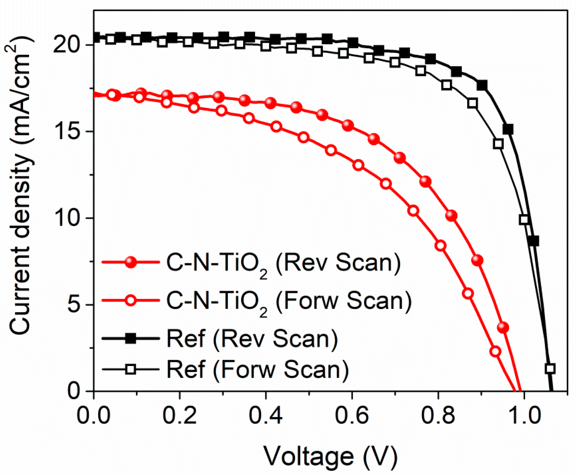
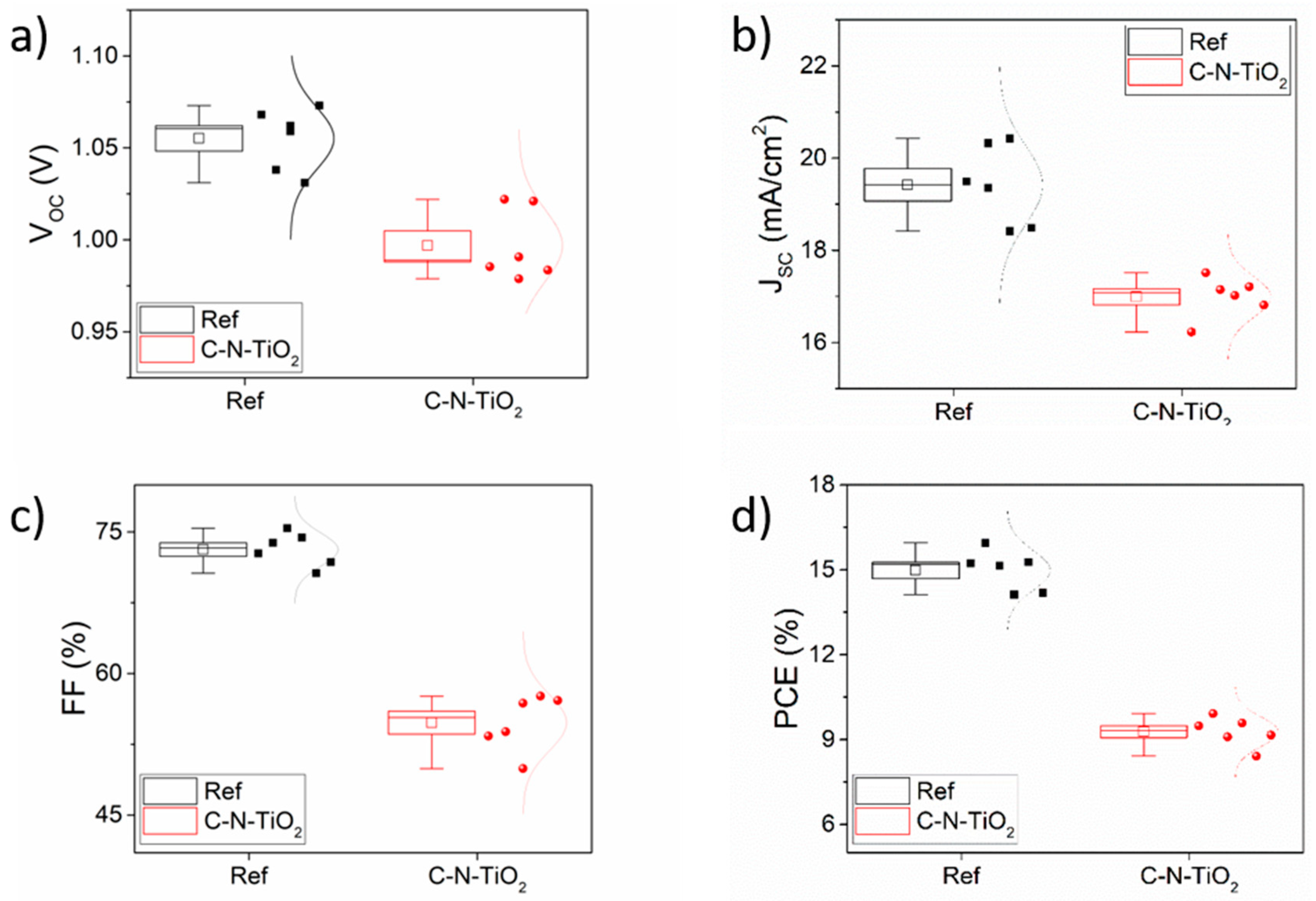
| Samples | Av VOC (V) | Av JSC (mA/cm2) | Av. FF (%) | Av. PCE (%) |
|---|---|---|---|---|
| Reference | 1.06 ± 0.02 | 19.42 ± 0.86 | 73.14 ± 1.76 | 14.98 ± 0.71 |
| C-N-TiO2 | 0.99 ± 0.02 | 16.99 ± 0.44 | 54.79 ± 2.98 | 9.28 ± 0.52 |
Publisher’s Note: MDPI stays neutral with regard to jurisdictional claims in published maps and institutional affiliations. |
© 2020 by the authors. Licensee MDPI, Basel, Switzerland. This article is an open access article distributed under the terms and conditions of the Creative Commons Attribution (CC BY) license (http://creativecommons.org/licenses/by/4.0/).
Share and Cite
Mouele, E.S.M.; Ngqoloda, S.; Pescetelli, S.; Di Carlo, A.; Dinu, M.; Vladescu, A.; Parau, A.C.; Agresti, A.; Braic, M.; Arendse, C.J.; et al. Spin Coating Immobilisation of C-N-TiO2 Co-Doped Nano Catalyst on Glass and Application for Photocatalysis or as Electron Transporting Layer for Perovskite Solar Cells. Coatings 2020, 10, 1029. https://doi.org/10.3390/coatings10111029
Mouele ESM, Ngqoloda S, Pescetelli S, Di Carlo A, Dinu M, Vladescu A, Parau AC, Agresti A, Braic M, Arendse CJ, et al. Spin Coating Immobilisation of C-N-TiO2 Co-Doped Nano Catalyst on Glass and Application for Photocatalysis or as Electron Transporting Layer for Perovskite Solar Cells. Coatings. 2020; 10(11):1029. https://doi.org/10.3390/coatings10111029
Chicago/Turabian StyleMouele, Emile Salomon Massima, Siphelo Ngqoloda, Sara Pescetelli, Aldo Di Carlo, Mihaela Dinu, Alina Vladescu, Anca Constantina Parau, Antonio Agresti, Mariana Braic, Christopher J. Arendse, and et al. 2020. "Spin Coating Immobilisation of C-N-TiO2 Co-Doped Nano Catalyst on Glass and Application for Photocatalysis or as Electron Transporting Layer for Perovskite Solar Cells" Coatings 10, no. 11: 1029. https://doi.org/10.3390/coatings10111029
APA StyleMouele, E. S. M., Ngqoloda, S., Pescetelli, S., Di Carlo, A., Dinu, M., Vladescu, A., Parau, A. C., Agresti, A., Braic, M., Arendse, C. J., & Petrik, L. F. (2020). Spin Coating Immobilisation of C-N-TiO2 Co-Doped Nano Catalyst on Glass and Application for Photocatalysis or as Electron Transporting Layer for Perovskite Solar Cells. Coatings, 10(11), 1029. https://doi.org/10.3390/coatings10111029