Service Behavior of Nitride Layers of Steels for Military Applications


Department of Mechanical Engineering, Faculty of Military Technology, University of Defence in Brno, Kounicova 65, 612 00 Brno, Czech Republic
*
Author to whom correspondence should be addressed.
Coatings 2020, 10(10), 975; https://doi.org/10.3390/coatings10100975
Submission received: 26 September 2020
/
Revised: 8 October 2020
/
Accepted: 12 October 2020
/
Published: 14 October 2020
Abstract
:Steels which are utilized in the manufacturing of specific parts of military technology such as crankshafts of engines in heavy-duty vehicles or barrels of guns must be subsequently modified by heat treatment according to the requirements of customers. Despite the hard surface of martensitic structure obtained by hardening process, steels have a low wear resistance and high values of coefficient of friction. To improve these parameters and due to the fact that many of steels which are utilized for manufacturing of mentioned parts are also categorized as Nitralloy steels, in this paper, the improvement in these properties of chosen steels by the application of plasma nitriding has been studied. The steel equivalent 17Ni4CrMo (i.e., CSN 41 6720) and equivalent 42CrMo4 (i.e., CSN 41 5142) were chosen for the study. The chemical composition of chosen steels was verified by optical emission spectrometry. The microstructure and the diffusion layer were observed by optical microscopy due to the evaluation of layer parameters important for the lifetime. ZWICK ZHU 2.5 was used for a measurement of the universal hardness of the surface and values of graphs of microhardness were obtained by the device LM 247AT LECO from a cross-section of samples. The coefficient of friction was determined by Bruker CERT-UMT-3 with a ball-on-disc method. The parameters of wear paths were obtained by Talysurf CLI 1000. After the application of plasma nitriding technology, the hardness of both steels was rapidly increased in comparison with non-nitrided samples. According to the comparison of coefficients of friction with respect to the parameters of the measurement, the coefficient of friction of nitrided samples decreases with increasing temperature, which is essential knowledge for the weapon industry, especially the construction of bore barrel.
1. Introduction
The contemporary trend in the automotive and weapon industry of constantly improving the performance of special parts of weapons and engines, while decreasing the weight and dimension of weapon and engines’ parts at the same time, has the effect of higher requirements for quality [1]. The mechanical parts of systems are innovating due to needs in the “army” area, especially in the sphere of the current trend of development of autonomous systems [2]. In these days, the industry of material technology has reached some limits of improvement in material properties. As a consequence of this fact, an effort is being made to find other materials with appropriate properties, or a combination of properties of known materials which are more suitable for special deployment in a military environment. The fundamental properties of parts are predetermined by the material from which they are made. A material is characterized by many properties which are significant for use. Some properties predetermine the material directly for some purposes, others only modify the behavior of the material a little, so these properties must be considered in cooperation with others [3,4]. While selecting a material, other non-technical properties such as economy and ecology must unfortunately be respected. The economy is huge reason for using surface technologies. In many cases, we are not able to select a perfect material that exactly meets our requirements. The technology of material development seems to be very expensive, therefore it is more effective and cheaper to use the available material with a combination of appropriate surface technologies [5]. Due to combined stresses, high pressure and also the abrasion, which must resist, the engine’s crankshaft and the barrel of the small arm weapon have been chosen as referential parts [6,7]. The quality of the face of crankshafts or barrels, specifically surface roughness and dimensional accuracy, is closely related to material characteristics. The knowledge in the sphere of material characteristics is really important for the judgement of the appropriateness of a material for its purpose. Apart from other material characteristics, the chemical composition and microstructure of the material also need to be mentioned, which influence the ability to follow chemical and thermal processing as well as the application of special surface technologies. However, care must be taken. Not all known surface technologies are suitable for application in a special environment. Nowadays, the most commonly used methods of modification of crankshaft’s and barrel surfaces are surface hardening and carburizing. A less commonly used method of surface modification is nitriding or ferritic nitocarburizing. A product of all these technologies is a modified part of the surface known as the surface layer. Methods such as surface hardening and carburizing are based on steel quenching from high temperatures (above critical temperature), whereby residual stress and geometrical deformations in the surface of the resulting products may occur. In case of nitriding, the temperature is significantly lower, generally in range of 490–560 °C, thereby a higher accuracy of product geometry can be achieved, and thus it can be also used in a combination of surface treatments called a duplex [8,9,10,11]. Moreover, nitriding is applicable for treating the outer surfaces of highly exposed parts of military technology as well as for the inner surfaces of barrel bores of small arms, where parameters such as resistance to wear and hardness are essential as well as in the case of cutting tools [12,13]. Due to these facts, in this paper, the improvement in the surface properties of chosen steels by the application of plasma nitriding is studied.
2. Materials and Methods
A measure of the benefits of an application of plasma nitriding on the chosen steels was experimentally investigated. For the investigation, methods including a microstructure assessment, microhardness and universal hardness measurements accompanied by measurements of coefficient of friction under different conditions were utilized. The connection of all results introduces the main characteristics of the material and the benefit of the suggested technology.
2.1. Materials
The selection of the material and subsequent technologies is dependent on a real working environment of parts. Materials and technologies, especially surface technologies, must be tailored, and even more so in the case of barrels of weapons or special parts of military vehicles. Suitable steels for the manufacturing of barrels and crankshafts are listed below in Table 1.
Many of the mentioned steels are categorized as heat-treatable or alloy structural steels. The steels, including the grey cells in Table 1, also belong to the list of Nitralloy steels. Finally, the steels 42CrMo4 (i.e., CSN 41 5142) and 17Ni4CrMo (i.e., CSN 41 6720) were chosen for the study due to their characteristics and suitability for special parts of vehicles and weapons [16]. These steels are used for barrels and crankshafts.
2.2. Chemical Composition
At first, the verification of a chemical composition of the chosen steels was performed on the advanced CCD optical emission spectrometer Tasman Q4 (Bruker, Billerica, MA, USA) and was evaluated as an average value of five measurements. For an analysis of the material, a glow discharge is used for an atoms’ excitation. The chemical composition is defined according to an electromagnetic radiation, which is emitted by an electron falling to lower energy levels, and which is unique for every element.
2.3. Specimen Preparation
From each steel, three disk-type specimens with diameter Ø70 mm and thickness h = 26 mm were made. All specimens were hardened and tempered. Specimens were heat-treated in the furnace for 20 min in 840 °C. Subsequently, the same specimens were quenched into the water. Hardening was followed by 60 min of tempering at 600 °C. One specimen of each steel was left in a heat-treated state. Two remaining specimens of each steel were exposed by plasma-nitriding technology for 30 h in a furnace with a carefully controlled atmosphere 3H2:1N2 in temperature 500 °C. Finally, all specimens were marked numerically, as listed in Table 2.
2.4. Microstructure Evaluation
For evaluation of a microstructure, metallographic specimens had to be prepared. Cross-sections were cut off from an outer edge of all disk-type specimens, as mentioned in Section 2.3. The cross-sections were molded into the thermoplastic powder subsequently. The samples were wet ground with a sandpaper and polished by a velvet with a diamond paste with grains of size 1 µm. The samples’ surface, thus prepared, was etched by 2% Nital. For an observation of a microstructure, the optical microscope Olympus DSX500i with magnifications 1000× and 600× was utilized.
2.5. Hardness Measurement
Microhardness was measured by LM247 AT LECO (Leco Corporation, 3000 Lakeview Ave, St. Joseph, MI, USA) equipped with AMH 55 and values were plotted as a function of a distance between indents and the surface of the nitride layer. In accordance with standards [17,18], it is possible to utilize the microhardness profile for determination of the thickness of the nitrided layer. Parameters of measurement were set to HV 0.05 (50 g load), 18 indents with feed 0.02–0.1 mm. Although the standard ISO 18203:2016(E) allows a utilizing load of 100 g as a minimum, according to the experiences of the department, a lower load was set [17]. By utilizing a load of 50 g, no significant changes in the curve of the microhardness profile in comparison with those where a 100 g load was used are visible, and moreover, the first indent can be performed at a lower distance from the surface. At first, the microhardness of non-nitrided specimens was measured. From five indents, an average value of core hardness rounded to tens was found. According to standards [17,18], a limit value of hardness is equal to an average value of a core hardness rounded to the nearest multiple of ten increased by 50 HV.
Generally, the hardness is defined as a resistance of the material to being penetrated by a foreign, harder material [19]. Unlike universal hardness, most of the tests of hardness measurement are based on an evaluation of hardness from the indents’ area after release of the loading force. Therefore, the elasticity of the material is ignored. The universal hardness measurement is different due to depth sensitive indentation instrument, which is able to continuously record the load and depth of indent during the measurement [19]. Due to this fact, the universal hardness is one of the parameters utilized for an assessment and comparison of the layers and surface’s properties [20]. The universal hardness measurement was performed by ZWICK ZHU 2.5 (ZWICK, Ulm, Germany).
2.6. Tribological Measurements
Tribological measurement was performed to check the behavior of the surface layers created by surface technology on both steels. The method called Ball-on-Disc was utilized for verification of surface parameters during friction. The output of this method is a coefficient of friction “COF”. An experimental comparison of surface of nitride and non-nitride steels was performed. The COF is dimensionless quantity which equals the quotient of normal and friction force [21]. The measurement was conducted on Bruker CERT UMT-3 TriboLab (Bruker, Billerica, MA, USA) in agreement with ASTM G99-95a [22]. Bruker’s TriboLab measurement method is based on indenting a ball by a predetermined force into the specimen’s surface. The specimen is rotatably attached to the device and the ball is fixed. At first, the following measurement parameters must be determined: radius, temperature, time of measurement, loading, number of rotations and angular speed. After switching on the device, the specimen starts to rotate, and the ball scratches a circle track to the specimen. The device continuously coevaluates the COF from the resisting force. The device provides the values of COF in dependence on time. On each, sample three or four measurements were performed. In one case of those measurements, the temperature was set to 80 °C. Other measurements were performed at 23 °C.
In general, it is possible to classify four phases of surface degradation within the measurement of COF:
- Initiation of wear;
- Mutual adaptation of contact surfaces and creation of the layer;
- Stabilization of the COF;
- Rupture of the layer and its destruction to the base material [23].
The first phase starts with a contact of the ball with the surface. For this phase, an intensive increase in COF is characteristic, caused by the interaction of the indenter with surface’s roughness. By the influence of wear, macroparticles form and are stuck in a track, which creates a thin layer [23]. In the second phase, the thickness of the layer increases, and the area of the track and its vicinity is heated. The increase in temperature is followed by oxidation. The values of COF are unstable in this phase due to ruptures, which are initialized in the layer created by macroparticles, followed by the formation of debris. The debris of a layer are moved around the wear track, which causes abrasive wear. Those two phases are characterized as “running–in” [24]. In the third phase, called “steady–state wear”, the surface of a wear track is coated by a thin layer of oxides, which causes stabilization of COF. In comparison with other phases, the third phase lasts a long time [24]. The fourth phase begins by the destruction of the wear-resistive layer and the COF increases rapidly. All measurements were ended during the steady-state wear phase, therefore the last phase is not visible in graphs of measurements. To compare the results measured with different pre-sets, the most important was to find out the dependence between pre-sets of parameters and the results of the measurement right at the beginning of the COF measurement. By this step, the comparison of incomparable results of measurements was eliminated. According to the analysis of the measurement’s results, the following dependence between pre-sets and results was found:
- Influence of circle path radius on results of COF was not confirmed;
- In this case, a change in an angular velocity affects results solely after an increase near to the value 1000 rpm and above;
- By an increase in the indenter’s load, the higher COF was detected;
- The effect of different temperatures on the results of the measurements is significant.
Note: A tungsten-carbide ball was used as an indenter in all measurements. The conclusions are drawn from a comparison of the results measured on the specimens of the same steel with an application of the same manufacturing technology.
Subsequently, based on the knowledge of the dependence of these parameters, it was possible to combine the results of measurements performed on different specimens. According to the bullet points above, the combined results were measured with pre-sets of the same load and temperature, optional radius and angular velocity, with values between 500 and 750 rpm.
2.7. Assessment of Wear
Due to a little uneven wear in a wear path, the formula for a calculation of a decrease in mass mentioned in standard ASTM G99-95a [22] was not utilized for assessment of the wear. The assessment was performed according to the results obtained by a measurement of the depth of wear paths on Talysurf CLI 1000 equipped with a program Talysurf Map. The program assessed the results of the paths’ profiles measurement, and removed errors and deviations of the results caused by a surface’s waviness. Three measurements on each path were performed. An average value of a depth of these three measurements was set as a comparative parameter.
3. Results and Discussion
By utilization of the results of experimental measurements, parameters of surfaces of nitrided specimens in comparison with non-nitrided specimens were evaluated.
3.1. Chemical Composition
The results of measurement of chemical composition obtained by the optical emission spectrometer Tasman Q4 Bruker are listed in Table 3 and Table 4.
The results confirmed that chemical composition of steels corresponds with their datasheets. Besides well-known factors such as the initial state of a steels’ microstructure after heat treatment, an exposition time, and the temperature and parameters of chemical-heat treatment atmosphere, according to the literature, a chemical composition also significantly influences the resulting properties of nitride layers [25,26]. Chemical composition measurements showed significant differences between the chemical compositions of the selected steels. Therefore, differences between the resulting nitride layers of chosen steels are also assumed. A purpose of nitriding is the achievement of better surface properties including an increase in hardness, fatigue, wear and corrosion resistance and a decrease in the value of COF and a sensitivity to a crack’s initiation within cyclic loading [25,26,27]. To obtain favorable surface properties, a sufficient depth of a nitride layer is also significant in the most cases of applications of nitriding. The depth of a layer is nearly connected with a concentration of nitrogen which depends on its diffusion rate [26]. Due to the high similarity of atomic radii of carbon (71 pm) and nitrogen (65 pm), these interstitial elements can occupy the same positions in a crystalline lattice. Therefore, an assumption is that a decrease in the content of carbon in a steel could induce an increase in the diffusion capability of nitrogen. Nevertheless, this phenomenon is hard to describe, and other alloying elements have an impact on resulting diffusion rate of nitrogen. In general, an increase in the content of substitutional alloying elements, including chromium, molybdenum, nickel, tungsten and manganese, causes a decrease in the diffusion rate of nitrogen [9,10]. Elements such as chromium, molybdenum and tungsten, contained in the selected steels, which retard the rate of nitrogen diffusion by a formation of hard nitrides and carbides, are involved in an increase in the surface’s hardness. Nickel, unlike the other mentioned substitutional elements, does not form nitrides. Thus, the nickel has the most negative impact on the diffusion of nitrogen [9,10]. According to the information about the impact of the alloying elements mentioned above, it is possible to assume that the positive effect of higher content of nitrides-forming elements on the increase in hardness in case of the steel equivalent 17Ni4CrMo (i.e., CSN 41 6720) will be compensated by a high content of nickel, exceeding 4 wt.%. Therefore, similar parameters of nitride layers of chosen steels are expected.
3.2. Microstructure Evaluation
The microstructure of the hardened and tempered steels equivalents 17Ni4CrMo (i.e., CSN 41 6720) and 42CrMo4 (i.e., CSN 41 5142), shown in Figure 1, was observed with magnification 1000×.
By the observation of microstructure of non- nitrided specimens after etching by 2% Nital, the presence of coarse-grained martensite with marks of sorbite and bainite was detected. Those structural phases are products of the heat treatment. Very brittle Martensitic structure, obtained by hardening, is partially formed to ferrite and cementite, which creates phases known as sorbite and bainite within tempering. The newly created structure has a lower hardness than martensite obtained by hardening, but it is tougher. The observed microstructures shown in Figure 1 correspond with heat treatment applied on the specimens.
3.3. Hardness
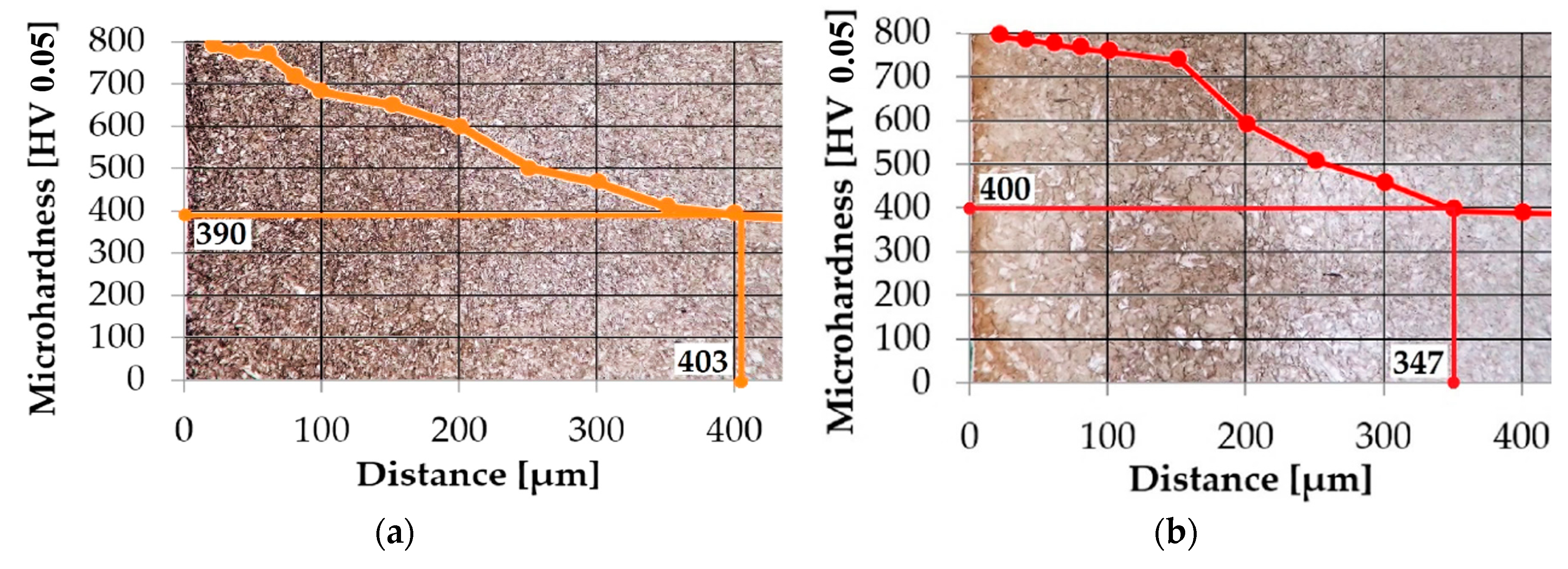
Two different methods, microhardness and universal hardness, were used for the hardness measurement of the steels. The measurement of the microhardness profiles was utilized for the determination of the depth of the diffusion layer. Figure 2 represents the profiles of microhardness, composed with an appropriate microstructure of the surface area of the nitrided steels in the background.
- Limit value of microhardness of steel equivalent 42CrMo4 (i.e., CSN 41 5142) as NHD 390 HV 0.05 = 403 µm was assessed;
- In case of steel equivalent 17Ni4CrMo (i.e., CSN 41 6720) the value was evaluated as NHD 400 HV 0.05 = 347 µm.
Figure 3 is focused on a comparison of microhardness profiles of the steels.
Although the thicknesses of layers assessed by the test of microhardness were different, Figure 3 shows that the microhardness of steels after plasma nitriding is almost the same until a depth of 500 µm. Close to the surface, a microhardness maximum was assessed in both cases as almost twice as high than the microhardness of the core.
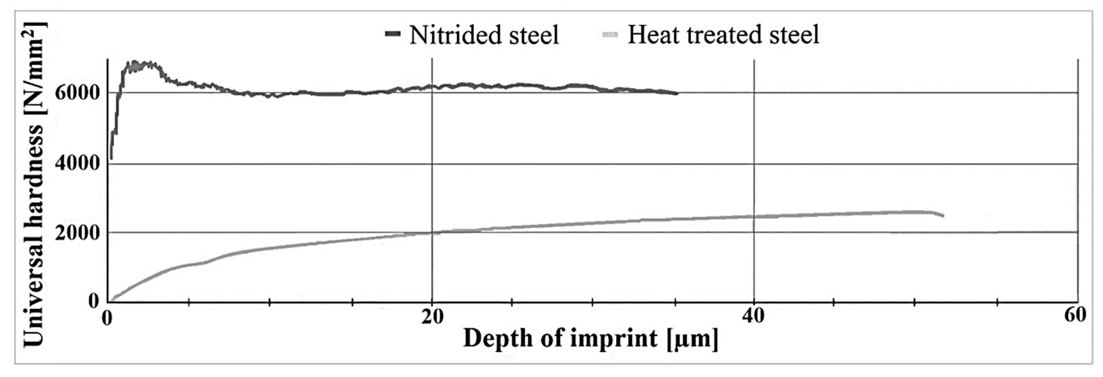
For a better perception of the resistance of the surface to be penetrated by a foreign harder material, the universal hardness was measured.
On Figure 4, a significant difference between the universal hardness of heat-treated steel with and without application of nitriding is visible. The bottom curve represents non-nitrided steel. It is evident that even a minimal load causes a permanent deformation. Over a value of 2000 N/mm2 the material is not able to resist a further loading, and the depth of the indent increases rapidly. An upper curve, which represents nitrided steel, implies that the surface of nitrided steel is able to resist much higher loading than the surface of solely heat-treated steel.
3.4. Coefficient of Friction
After the acceptance of the restrictions mentioned in Section 2.6, the first measurements at the room temperature were performed.
3.4.1. Influence of Plasma Nitriding on COF Measured at Room Temperature
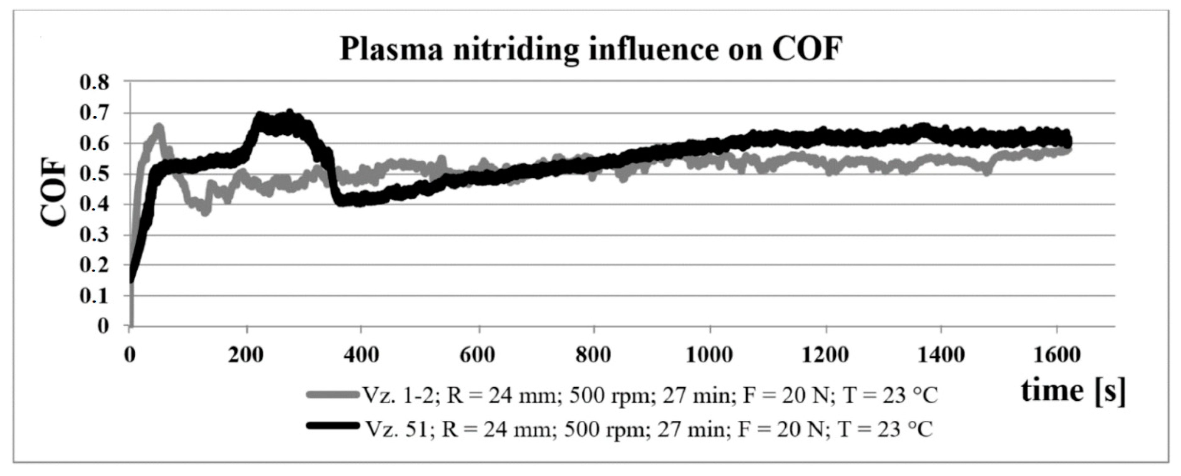
The plasma nitriding effect on values of the COF of steel equivalent 42CrMo4 (i.e., CSN 41 5142) is shown in Figure 5. By the application of PN, the running-in phase of COF was shortened from the original 350 s to approximately 100 s. Within the steady state wear, the graph of COF of nitrided specimen is smoother and more stable, unlike the specimen without PN. In spite of the previous description, the values of COF are very similar in the second half of the graph, so the improvement was not confirmed.
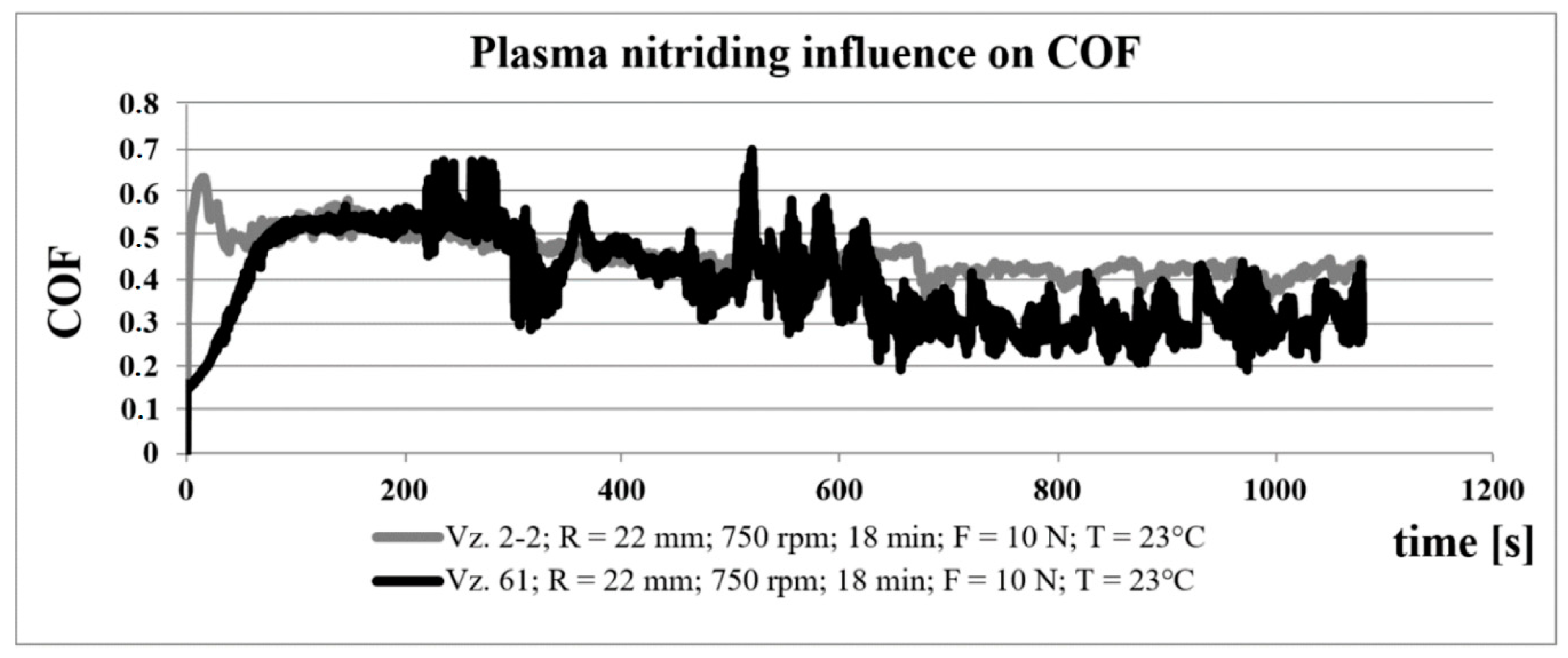
The Figure 6 shows the behavior of the COF after an application of PN on the steel equivalent 17Ni4CrMo (i.e., CSN 41 6720). The same as in a previous case, the graph is smoother, and the running-in phase is shortened. The values of COF of the nitrided specimen are greater in the second half of the measurement in comparison with the non-nitrided specimen.
3.4.2. Influence of Plasma Nitriding on COF Measured at Higher Temperatures
To approach the conditions of measurements to working conditions of crankshafts, the temperature in further measurements was set to 80 °C. This temperature is typical for the working temperature of engines.
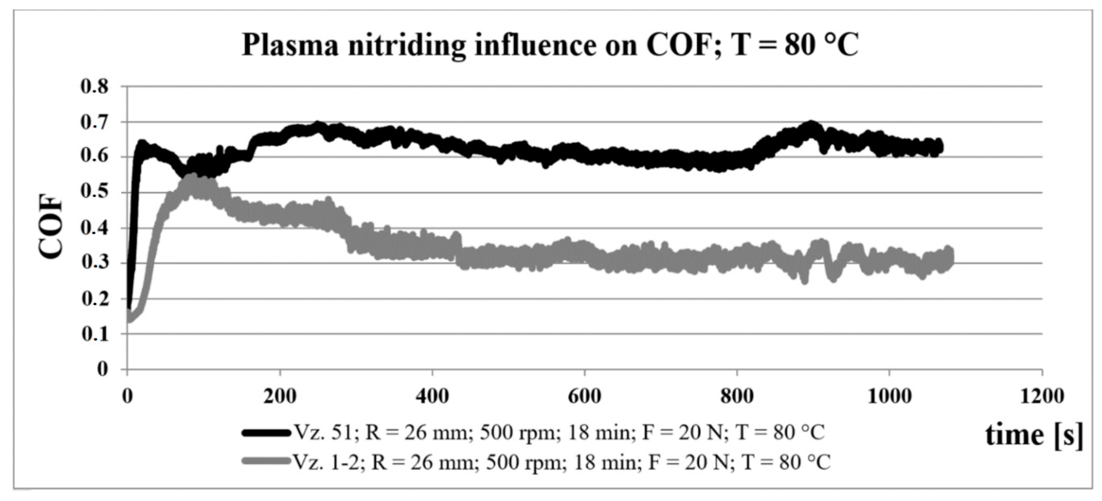
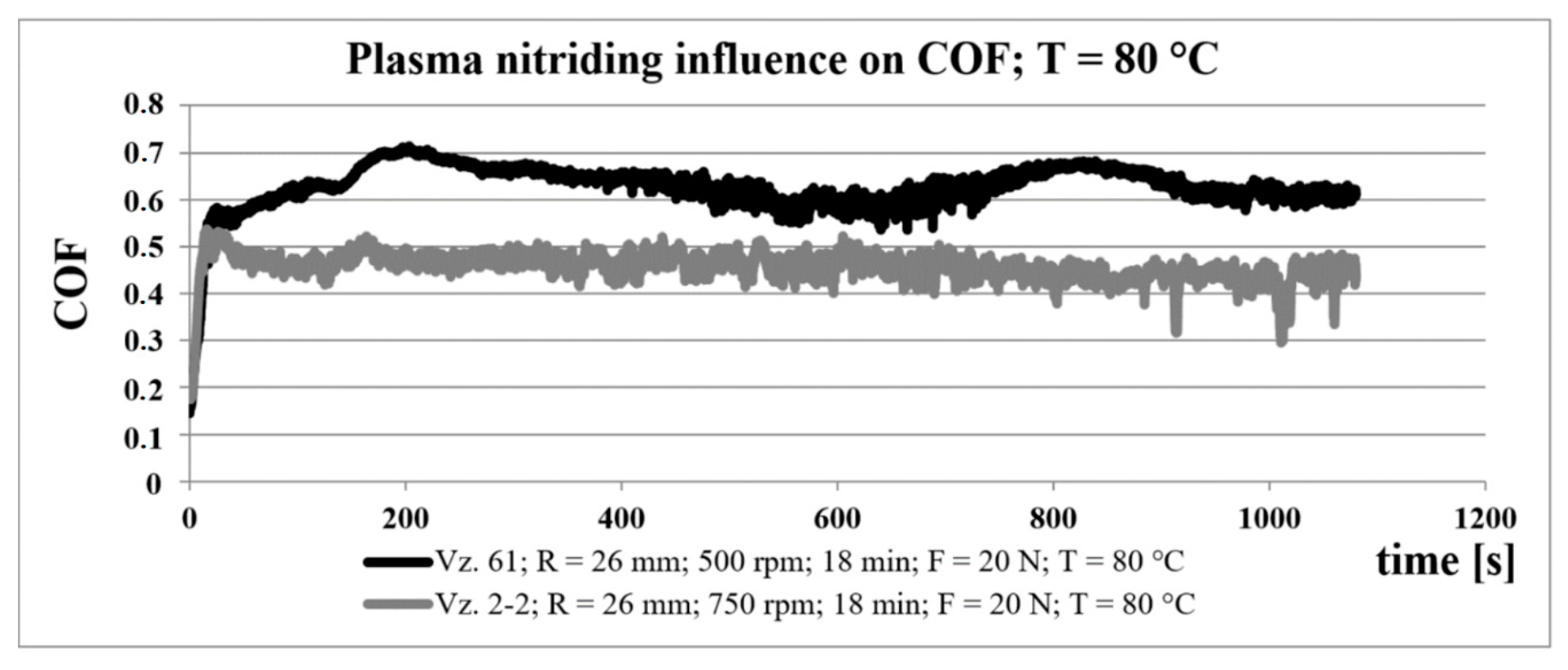
In comparison with the results obtained by measurements of COF at room temperature, which are mentioned in Section 3.4.1, the beneficial influence of plasma nitriding is much more visible in measurements at higher temperature. A decrease in the values of COF was observed in both cases of chosen steels. By observation of the COF of nitrided specimens of both steels shown in Figure 7 and Figure 8, significant differences in stable-state phase were detected. In case of nitrided steel equivalent 42CrMo4 (i.e., CSN 41 5142) a moderate decrease in COF until the value 0.3 appeared, whereas the values of COF of steel equivalent 17Ni4CrMo (i.e., CSN 41 6720) are constant for the whole duration of measurement.
The temperature-dependence of COF can be attributed to the creation of oxides in the wear trace. As is described in the literature [28,29], oxides created in contact surfaces act like a thin protective slide layer with a lower value of friction coefficient. In the process of wear, some macroparticles are ripped out of the surface of thin layers and cause the increase in surface degradation.
In comparison with heat-treated surfaces without surface technology, the nitrided surfaces are harder and more wear-resistive due to the presence of oxides and nitrides. The newly created compound layer composed of oxides and nitrides acts as a dry lubricant. Thus, in the case of nitrided surfaces, the positive effect of the compound layer at higher temperatures outweighs the abrasion caused by macroparticles, which is manifested by decreasing COF.
Differences between the COF of nitrided specimens manufactured from different steels are connected with differences in the content of alloying elements in their structure. Elements such as nickel and chromium significantly influence the creation of oxides on the surface.
3.5. Assessment of Wear
At the end of the experimental part, an average depth of a wear paths, as a referential parameter of a measure of wear, was assessed. The average values of wear paths’ depth with appropriate parameters of tribological measurements are listed in Table 5.
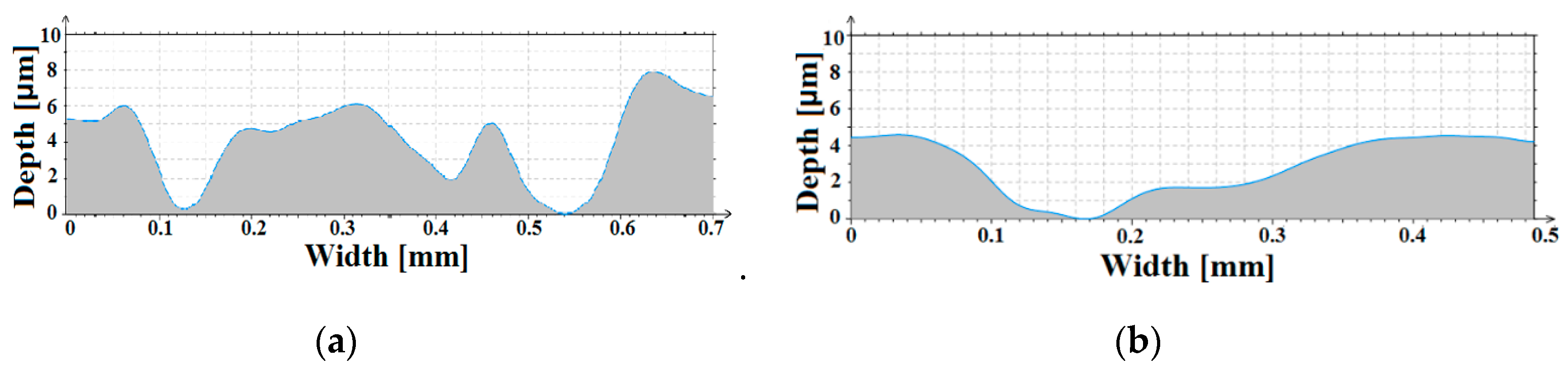
By comparison of nitrided specimens with non-nitrided specimens manufactured from steel equivalent 42CrMo4 (i.e., CSN 41 5142) a decrease in wear paths’ depth by the application of PN was found. The values of depth are lower in the case of measurement at room temperature as well as at higher temperature.
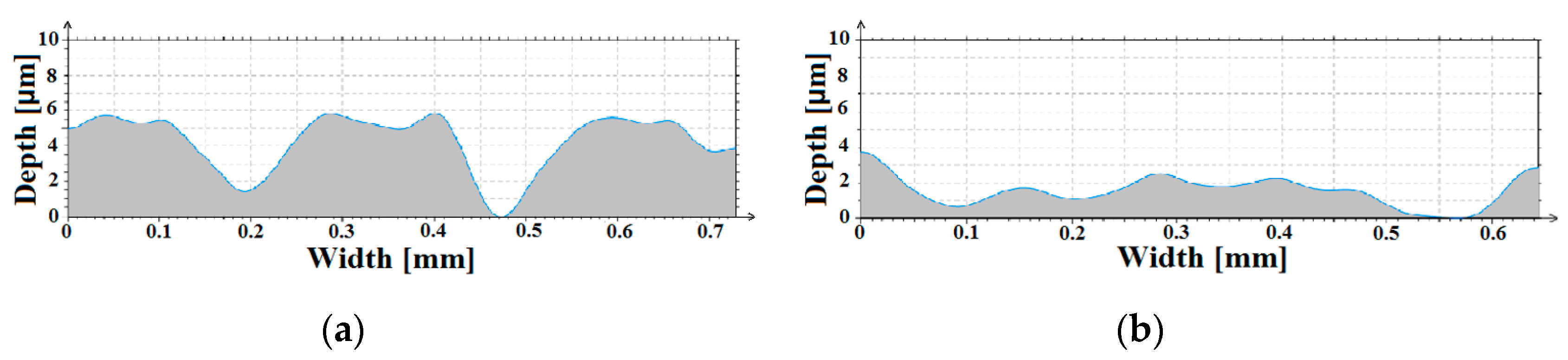
In case of steel equivalent 17Ni4CrMo (i.e., CSN 41 6720), differences between heat-treated and nitrided specimens are more evident. Whereas the depth of the wear path of nitrided steel equivalent 42CrMo4 (i.e., CSN 41 5142) increased a little at a higher temperature of measurement, in the case of nitrided steel equivalent 17Ni4CrMo (i.e., CSN 41 6720) the depth of wear path at higher temperature decreased.
4. Conclusions
This paper is devoted to an investigation of the possibilities of the surface property improvement of steels equivalent to 42CrMo4 (i.e., CSN 41 5142) and equivalent 17Ni4CrMo (i.e., CSN 41 6720) by an application of plasma nitriding. For the investigation, methods including a microstructure assessment, microhardness and universal hardness measurements, accompanied with measurements of wear and coefficient of friction under different conditions were utilized.
An increase in the surface microhardness by the application of plasma nitriding was proved. Maximums of surface microhardness were similar and achieved doubled values in comparison with the microhardness of the core in both cases of steels. The depth of the nitride layer was increased by approximately 50 μm in case of the steel equivalent 42CrMo4 (i.e., CSN 41 5142) in comparison with the steel equivalent 17Ni4CrMo (i.e., CSN 41 6720). With respect to the high similarity of microhardness profiles, the difference between the depths of nitride layers can be attributed to a difference in the microhardness of cores. The negative influence of nickel concentration for the diffusion process was proved [9].
The universal hardness measurement was also utilized for an evaluation of the beneficial impact of the application of plasma nitriding on the surface hardness. While the signs of a surface resistance to be penetrated without permanent deformation in the case of non-nitrided specimen almost did not appear, nitrided surface was able to be loaded by more over than 4000 N/mm2 without significant deformation.
By the tribological measurement, the impact of plasma nitriding on the values of COF was assessed. The beneficial effect of plasma nitriding on COF was proved by all measurements. The results showed that values of COF of nitride surface measured at temperatures similar to the working conditions of special military parts are much more favorable in comparison with the values measured at the lower temperature. The most favorable values were obtained with the steel equivalent 42CrMo4 (i.e., CSN 41 5142).
The assessment of wear subsequently showed the same phenomenon mentioned in the case of measurement of COF. The wear of nitride surfaces, assessed by using the average depths of wear tracks obtained by tribological measurement, was lower in all cases of measurement in comparison with the heat-treated ones. The largest differences between the wear of the nitrided and the non-nitrided surfaces were observed in the case of tracks obtained by tribological measurements at the higher temperature. The greatest improvement was achieved with the steel equivalent 17Ni4CrMo (i.e., CSN 41 6720).
From these results it can be seen that the application of plasma nitriding in the manufacturing of special high stressed parts is beneficial, and it is possible to recommend a wider utilization of plasma nitriding in the sphere of the manufacturing of military equipment, mainly in connection with small arm weapons, where nitriding represents an environmentally friendly substitution for chromium plating, a currently prohibited, but previously commonly utilized technology for the treatment of barrel bores.
Author Contributions
Conceptualization, J.P. and Z.P.; methodology, J.P., Z.P., and D.D.; formal analysis, J.P.; investigation, J.P.; resources, J.P., Z.P., and D.D.; writing—original draft preparation, J.P.; writing—review and editing, Z.P. and D.D.; supervision, Z.P. and D.D. All authors have read and agreed to the published version of the manuscript.
Funding
This research received no external funding.
Acknowledgments
The work presented in this paper has been supported by the specific research project 2020 “SV20-216” at the Department of Mechanical Engineering, University of Defence in Brno and the Project for the Development of the Organization “DZRO K201”.
Conflicts of Interest
The authors declare no conflict of interest.
References
- Barényi, I.; Majerík, J.; Pokorný, Z.; Sedlák, J.; Bezecný, J.; Dobrocký, D.; Jaroš, A.; Eckert, M.; Jambor, J.; Kusenda, R. Material and technological investigation of machined surfaces of the OCHN3MFA steel. Met. Mater. 2019, 57, 131–142. [Google Scholar] [CrossRef] [Green Version]
- Turo, T.; Neumann, V.; Krobot, Z. Aspects of Technical Requirements for the Future Autonomy of Military Vehicles. In Modelling and Simulation for Autonomous Systems; Mazal, J., Ed.; Lecture Notes in Computer Science; Springer International Publishing: Cham, Switzerland, 2018; pp. 374–380. ISBN 978-3-319-76071-1. [Google Scholar] [CrossRef]
- Hluchý, M.; Kolouch, J. Strojírenská Technologie 1; Scientia Publisher: Prague, Czech Republic, 2007. [Google Scholar]
- Macek, K. Strojírenské Materiály; ČVUT Publisher: Praha, Czech Republic, 2003. [Google Scholar]
- Klanica, O.; Svoboda, E.; Joska, Z. Changes of the surface texture after surface treatment HS6-5-2-5 steel. Manuf. Technol. 2015, 15, 47–53. [Google Scholar] [CrossRef]
- Hromádko, J. Spalovací Motory: Komplexní Přehled Problematiky Pro Všechny Typy Technických Automobilních Škol; Grada Publisher: Prague, Czech Republic, 2011. [Google Scholar]
- Fonte, M.; Freitas, M.; Reis, L. Failure analysis of a damaged diesel motor crankshaft. Eng. Fail. Anal. 2019, 102, 1–6. [Google Scholar] [CrossRef]
- Pišek, D. Chemicko-Tepelné Zpracování Ocelí. Bachelor’s Thesis, Vysoké učení technické v Brně, Brno, Czech Republic, 2015. [Google Scholar]
- Pokorny, Z.; Dobrocky, D.; Kadlec, J.; Studeny, Z. Influence of Alloying Elements on Gas Nitriding Process of High-Stressed Machine Parts of Weapons. Met. Mater. 2018, 56, 97–103. [Google Scholar] [CrossRef] [Green Version]
- Totten, G.E. Steel Heat Treatment: Metallurgy and Technologies, 2nd ed.; Taylor & Francis: Boca Raton, FL, USA, 2007. [Google Scholar]
- Dobrocky, D.; Pokorny, Z.; Studeny, Z.; Doan, T.V. Analyse of Tribological Properties of Layers Created by Plasma Nitriding + DLC. Manuf. Technol. 2018, 18, 379–386. [Google Scholar] [CrossRef]
- Pokorný, Z.; Hrubý, V.; Stránský, K.; Kadlec, J. Properties of plasma nitrided layers in deep cavities. In Proceedings of the METAL 2011, 20th Anniversary International Conference on Metallurgy and Materials, Brno, Czech Republic, 18–20 May 2011; TANGER Ltd.: Ostrava, Czech Republic, 2011; pp. 786–790. [Google Scholar]
- Jaros, A.; Sedlak, J.; Vondra, J. Investigation of the influence of PVD coatings for dry groove milling. Mm Sci. J. 2018, 2018, 2516–2520. [Google Scholar] [CrossRef]
- Arnošt, D. Tankové Spalovací Motory od Historie až po Současnost; Vysoké učení technické v Brně: Brno, Czech Republic, 2009. [Google Scholar]
- Bolek, A.; Kochman, J. Části Strojů: 2; SNTL Publisher: Prague, Czech Republic, 1990. [Google Scholar]
- Doan, T.V.; Dobrocky, D.; Pokorny, Z.; Kusmic, D.; Nguyen, V.T. Effect Of Plasma Nitriding On Mechanical And Tribological Properties Of 42CrMo4 Steel. In Proceedings of the ABAF 2016, 17th International Conference on Advanced Batteries, Accumulators and Fuel Cells, Brno, Czech Republic, 28–31 August 2016; ECS Transaction: Brno, Czech Republic, 2016; Volume 74, pp. 231–238. [Google Scholar]
- ISO 18203:2016. Steel–Determination of Thickness of Surface Hardened Layers; The International Organization for Standardization: Geneva, Switzerland, 2016. [Google Scholar]
- EN ISO 6507-1:2018. Metallic Materials-Vickers Hardness Test-Part 1: Test Method; The International Organization for Standardization: Geneva, Switzerland, 2018. [Google Scholar]
- EN ISO 14577-1:2015. Metallic Materials—Instrumented Indentation Test for Hardness and Materials Parameters–Part 1: Test Method; European Committee for Standardzation: Brussels, Belgium, 2015. [Google Scholar]
- Joska, Z.; Kadlec, J.; Hrubý, V.; Mrázková, T.; Maňas, K. Characteristics of Duplex Coating on Austenitic Stainless Steel. Key Eng. Mater. 2011, 465, 255–258. [Google Scholar] [CrossRef]
- Doan, T.V.; Kusmič, D.; Pospíchal, M.; Tran, Q.D.; Nguyen, V.T. Friction and Wear Behaviour of 42CrMo4 Steel Treated by Tenifer, Hard Chrome and Plasma Nitriding Technologies. Manuf. Technol. 2017, 17, 168–174. [Google Scholar] [CrossRef]
- ASTM. 99-95a Standard Test Method for Wear Testing with a Pin on Disc Apparatus; ASTM International: West Conshohocken, PA, USA, 2000. [Google Scholar]
- Kříž, A. Tribologická analýza PIN-ON-DISC. Metal 2004, pp. 1–8. Available online: https://opi.zcu.cz/TRIBOLOGICKA_ANALYZA_PIN-ON-DISC.pdf (accessed on 13 October 2020).
- Axén, N.; Hogmark, S.; Jacobson, S. Modern Tribology Handbook, Chapter 13: Friction and Wear Measurement Techniques; CRC Press: Boca Raton, FL, USA, 2001; pp. 493–510. [Google Scholar]
- Ptáček, L. Nauka o Materiálu II; CERM: Brno, Czech Republic, 1999; ISBN 80-7204-130-4. [Google Scholar]
- Peng, T.; Chen, Y.; Liu, X.; Wu, M.; Lu, Y.; Hu, J. Phase constitution control of plasma nitrided layer and its effect on wear behavior under different loads. Surf. Coat. Technol. 2020, 403. [Google Scholar] [CrossRef]
- Śnieżek, L.; Ślęzak, T.; Grzelak, K.; Hutsaylyuk, V. An experimental investigation of propagation the semi-elliptical surface cracks in an austenitic steel. Int. J. Press. Vessel. Pip. 2016, 144, 35–44. [Google Scholar] [CrossRef]
- Zhu, H.; Zhu, Q.; Tieu, A.K.; Kosasih, B.; Kong, C. A simulation of wear behaviour of high-speed steel hot rolls by means of high temperature pin-on-disc tests. Wear 2013, 302, 1310–1318. [Google Scholar] [CrossRef]
- Baccouch, Z.; Mnif, R.; Elleuch, R.; Richard, C. Analysis of friction, wear and oxidation behaviour of X40CrMoV5/Fe360B steel couple in an open-sliding contact. Proc. Inst. Mech. Eng. Part J J. Eng. Tribol. 2013, 228, 276–287. [Google Scholar] [CrossRef]
Publisher’s Note: MDPI stays neutral with regard to jurisdictional claims in published maps and institutional affiliations. |
Figure 1.
Microstructure of hardened and tempered material magnified 1000×; (a) steel equivalent 42CrMo4 (i.e., CSN 41 5142) on left; (b) 17Ni4CrMo (i.e., CSN 41 6720) on right.
Figure 1.
Microstructure of hardened and tempered material magnified 1000×; (a) steel equivalent 42CrMo4 (i.e., CSN 41 5142) on left; (b) 17Ni4CrMo (i.e., CSN 41 6720) on right.
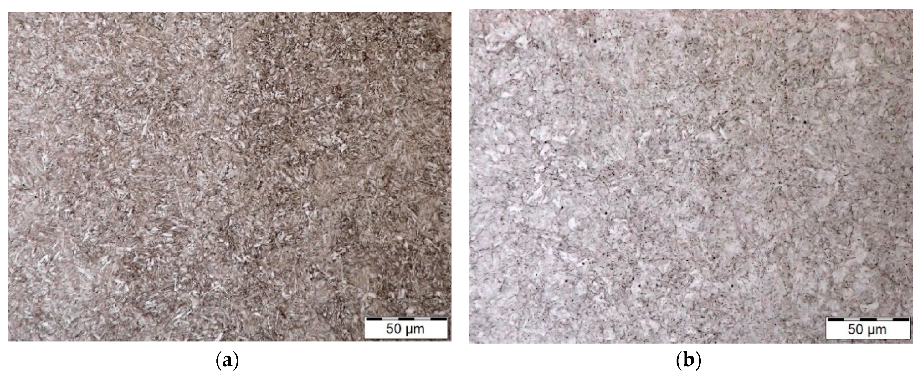
Figure 2.
Profiles of microhardness with appropriate microstructures in background; (a) steel equivalent 42CrMo4 (i.e., CSN 41 5142)–plasma nitrided on left; (b) steel equivalent 17Ni4CrMo (i.e., CSN 41 6720)—plasma nitrided on right; magnification of microstructure: 600×.
Figure 2.
Profiles of microhardness with appropriate microstructures in background; (a) steel equivalent 42CrMo4 (i.e., CSN 41 5142)–plasma nitrided on left; (b) steel equivalent 17Ni4CrMo (i.e., CSN 41 6720)—plasma nitrided on right; magnification of microstructure: 600×.

Figure 3.
Comparison of microhardness profiles of the steels after application of plasma nitriding.
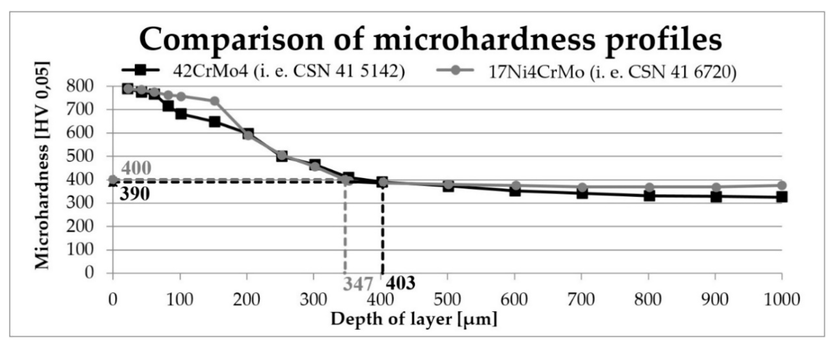
Figure 4.
Values of universal hardness depending on the depth of indent; instrumented hardness tester ZWICK ZHU 2.5; load: 196 N; time of measurement: 12 s; steel equivalent 42CrMo4 (i.e., CSN 41 5142).
Figure 4.
Values of universal hardness depending on the depth of indent; instrumented hardness tester ZWICK ZHU 2.5; load: 196 N; time of measurement: 12 s; steel equivalent 42CrMo4 (i.e., CSN 41 5142).

Figure 5.
Comparison of coefficient of friction (COF) of nitrided (vz. 1-2) and non-nitrided (vz. 51) specimens; steel equivalent 42CrMo4 (i.e., CSN 41 5142).
Figure 5.
Comparison of coefficient of friction (COF) of nitrided (vz. 1-2) and non-nitrided (vz. 51) specimens; steel equivalent 42CrMo4 (i.e., CSN 41 5142).

Figure 6.
Comparison of COF of nitride (vz. 2-2) and non-nitrided (vz. 61) specimens; steel equivalent 17Ni4CrMo (i.e., CSN 41 6720).
Figure 6.
Comparison of COF of nitride (vz. 2-2) and non-nitrided (vz. 61) specimens; steel equivalent 17Ni4CrMo (i.e., CSN 41 6720).

Figure 7.
Comparison of COF of nitrided (vz. 1-2) and non-nitrided (vz. 51) specimens; steel equivalent 42CrMo4 (i.e., CSN 41 5142); measured at higher temperature.
Figure 7.
Comparison of COF of nitrided (vz. 1-2) and non-nitrided (vz. 51) specimens; steel equivalent 42CrMo4 (i.e., CSN 41 5142); measured at higher temperature.

Figure 8.
Comparison of COF of nitrided (vz. 2-2) and non-nitrided (vz. 61) specimens; steel equivalent 17Ni4CrMo (i.e., CSN 41 6720); measured at higher temperature.
Figure 8.
Comparison of COF of nitrided (vz. 2-2) and non-nitrided (vz. 61) specimens; steel equivalent 17Ni4CrMo (i.e., CSN 41 6720); measured at higher temperature.

Figure 9.
Profiles of wear paths; steel equivalent 42CrMo4 (i.e., CSN 41 5142); performed by Talysurf CLI 1000. (a) Profile of wear path of non-nitrided specimen; vz. 51; R = 26 mm; 500 rpm; 18 min; F = 20 N; T = 80 °C—on left. (b) Profile of wear path of nitrided specimen; vz. 1-2; R = 26 mm; 500 rpm; 18 min; F = 20 N; T = 80 °C—on right.

Figure 10.
Profiles of wear paths; steel equivalent 17Ni4CrMo (i.e., CSN 41 6720); performed by Talysurf CLI 1000. (a) Profile of wear path of non-nitrided specimen; vz. 61; R = 26 mm; 500 rpm; 18 min; F = 20 N; T = 80 °C—on left. (b) Profile of wear path of nitrided specimen; vz. 2-2; R = 26 mm; 750 rpm; 18 min; F = 20 N; T = 80 °C—on right.


Table 1.
Materials used for manufacturing of crankshafts.
| Gasoline Engines | Gasoline and Diesel Engines | Diesel Engines (Alloyed Steels) | Diesel Engines (Upgraded Steel) | Diesel Engines (Hardened Steel) | Aircraft and Tank Engines |
|---|---|---|---|---|---|
| C35 | 34CrMo4 | 36Mn5 | C35 | 1.1191 | 30CrMoV9 |
| C45 | 34CrNiMo6 | 51CrV4 | 42CrMo4 | 35NiCr 6 | - |
| C55 | 17Ni4CrMo | 31NiCr 14 | 35NiCr 6 | - | - |
| 37MnSi5 | - | - | - | - | - |
| 36Mn5 | - | - | - | - | - |
| 1.7361 | - | - | - | - | - |
| 50CrV4 | - | - | - | - | - |
| 58CrV4 | - | - | - | - | - |
| 31NiCr14 | - | - | - | - | - |
Table 2.
Marking of specimens used in graphs.
| Steel | Applied Technology | |
|---|---|---|
| Heat Treatement (HT) | HT + Plasma Nitriding | |
| 42CrMo4 (i.e., CSN 41 5142) | Vz. 51 | Vz. 1-1, Vz. 1-2 |
| 17Ni4CrMo (i.e., CSN 41 6720) | Vz. 61 | Vz. 2-1, Vz. 2-2 |
Table 3.
Chemical composition of steel equivalent 42CrMo4 (i.e., CSN 41 5142) verified by Tasman Q4 Bruker (wt.%).
Table 3.
Chemical composition of steel equivalent 42CrMo4 (i.e., CSN 41 5142) verified by Tasman Q4 Bruker (wt.%).
| C | Mn | Si | P | S | Ni | Cr | Mo |
|---|---|---|---|---|---|---|---|
| OES/Bulk | |||||||
| 0.39 | 0.60 | 0.25 | 0.012 | 0.022 | 0.33 | 0.96 | 0.22 |
| Datasheet | |||||||
| 0.38–0.45 | 0.50–0.80 | 0.17–0.37 | <0.035 | <0.035 | <0.50 | 0.90–1.20 | 0.15–0.30 |
Table 4.
Chemical composition of steel equivalent 17Ni4CrMo (i.e., CSN 41 6720) verified by Tasman Q4 Bruker (wt.%).
Table 4.
Chemical composition of steel equivalent 17Ni4CrMo (i.e., CSN 41 6720) verified by Tasman Q4 Bruker (wt.%).
| C | Mn | Si | P | S | Ni | Cr | W |
|---|---|---|---|---|---|---|---|
| OES/Bulk | |||||||
| 0.15 | 0.398 | 0.25 | 0.013 | 0.025 | 4.118 | 1.542 | 0.82 |
| Datasheet | |||||||
| 0.14–0.21 | 0.25–0.55 | 0.17–0.37 | <0.035 | <0.035 | 4.00–4.50 | 1.35–1.65 | 0.80–1.20 |
Table 5.
Evaluation of wear.
| Specimen | Radius [mm] | Average Depth [μm] | Load [N] | Angular Velocity [rpm] | Initial Temperature [°C] |
|---|---|---|---|---|---|
| Vz.51 (CSN 41 5142) non-nitrided | 22 | 4.82 | 10 | 750 | 23 |
| 26 | 6.27 | 20 | 500 | 80 | |
| Vz.61 (CSN 41 6720) non-nitrided | 22 | 7.27 | 10 | 750 | 23 |
| 26 | 10.15 | 20 | 500 | 80 | |
| Vz.1-2 (CSN 41 5142) nitrided | 22 | 2.58 | 10 | 750 | 23 |
| 26 | 4.53 | 20 | 500 | 80 | |
| Vz.2-2 (CSN 41 6720) nitrided | 22 | 3.62 | 10 | 750 | 23 |
| 26 | 2.87 | 20 | 750 | 80 |
© 2020 by the authors. Licensee MDPI, Basel, Switzerland. This article is an open access article distributed under the terms and conditions of the Creative Commons Attribution (CC BY) license (http://creativecommons.org/licenses/by/4.0/).
Share and Cite
MDPI and ACS Style
Prochazka, J.; Pokorny, Z.; Dobrocky, D. Service Behavior of Nitride Layers of Steels for Military Applications. Coatings 2020, 10, 975. https://doi.org/10.3390/coatings10100975
AMA Style
Prochazka J, Pokorny Z, Dobrocky D. Service Behavior of Nitride Layers of Steels for Military Applications. Coatings. 2020; 10(10):975. https://doi.org/10.3390/coatings10100975
Chicago/Turabian StyleProchazka, Jiri, Zdenek Pokorny, and David Dobrocky. 2020. "Service Behavior of Nitride Layers of Steels for Military Applications" Coatings 10, no. 10: 975. https://doi.org/10.3390/coatings10100975
Note that from the first issue of 2016, this journal uses article numbers instead of page numbers. See further details here.