Electrochromic Properties of Li- Doped NiO Films Prepared by RF Magnetron Sputtering

Abstract
1. Introduction
2. Experimental
2.1. Preparation of NiO:Li Targets
2.2. Preparation of ECD s
2.3. Characteristics Analysis
3. Results and discussion
4. Conclusions
Author Contributions
Funding
Conflicts of Interest
References
- Lin, S.C. Low-E glass building materials market development. Materialsnet 2014, 332, 135–141. [Google Scholar]
- Alesanco, Y.; Viñuales, A.; Rodriguez, J.; Tena-Zaera, R. All-in-One Gel-Based Electrochromic Devices: Strengths and Recent Developments. Materials 2018, 11, 414. [Google Scholar] [CrossRef] [PubMed]
- Granqvist, C.G. Electrochromic devices. J. Eur. Ceram. Soc. 2005, 25, 2907–2912. [Google Scholar] [CrossRef]
- Sapp, S.A.; Sotzing, G.A.; Reynolds, J.R. High contrast ratio and fast-switching dual polymer electrochromic devices. Chem. Mater. 1998, 10, 2101–2108. [Google Scholar] [CrossRef]
- Platt, J.R. Electrochromism, a possible change of color producible in dyes by an electric field. J. Chem. Phys. 1961, 34, 862–863. [Google Scholar] [CrossRef]
- Moulki, H. Improved electrochromic performances of NiO based thin films by lithium doping: From single layers to devices. Electrochim. Acta 2012, 74, 46. [Google Scholar] [CrossRef]
- Jang, W.L. Electrical properties of Li-doped NiO films. J. Eur. Ceram. Soc. 2010, 30, 503. [Google Scholar] [CrossRef]
- Lu, H.W. The effects of UV-ozone treated ultra-thin Li2CO3-doped NiO film as the anode buffer layer on the electrical characteristics of organic light-emitting diodes. J. Alloy Compd. 2016, 682, 311. [Google Scholar] [CrossRef]
- Li, Y. One-step synthesis of Li-doped NiO as high-performance anode material for lithium ion batteries. Ceram. Int. 2016, 42, 14565. [Google Scholar] [CrossRef]
- Wei, L. Valence band edge shifts and charge-transfer dynamics in Li-Doped NiO based p-type DSSCs. Electrochim. Acta 2016, 188, 309. [Google Scholar] [CrossRef]
- Chang, J.Y.; Chen, Y.C.; Wang, C.M.; Wang, W.N.; Wen, C.-Y.; Lin, J.M. Electrochromic properties of lithium-doped tungsten oxide prepared by electron beam evaporation. Coatings 2019, 9, 191. [Google Scholar] [CrossRef]
- Inaba, H.; Iwaku, M.; Tatsuma, T.; Oyama, N. Electrochemical intercalation of cations into an amorphous WO3 film and accompanying changes in mass and surface properties. J. Electroanal. Chem. 1995, 387, 71–77. [Google Scholar] [CrossRef]
- Hercules, D.M. Electron spectroscopy: Applications for chemical analysis. J. Chem. Educ. 2004, 81, 1751–1766. [Google Scholar] [CrossRef]
- Chen, Y.C.; Wen, C.Y.; Wang, C.M.; Ho, C.W.; Lin, S.Y.; Chen, Y.L. Characterization of transition-metal oxide deposition on carbon electrodes for supercapacitor. Appl. Sci. 2016, 6, 413. [Google Scholar] [CrossRef]
- Avellaneda, C.O.; Bulhões, L.O.S. Intercalation in WO3 and WO3: Li films. Solid State Ion. 2003, 165, 59–64. [Google Scholar] [CrossRef]
- Yang, J.; Chen, R.; Fan, X.; Bao, S.; Zhu, W. Thermoelectric properties of silver-doped n-type Bi2Te3-based material prepared by mechanical alloying and subsequent hot pressing. J. Alloy Compd. 2006, 407, 330–333. [Google Scholar] [CrossRef]
- Stafström, S.; Brédas, J.L.; Epstein, A.J.; Woo, H.S.; Tanner, D.B.; Huang, W.S.; MacDiarmid, A.G. Polaron lattice in highly conducting polyaniline: Theoretical and optical studies. Phys. Rev. Lett. 1987, 59, 1464–1467. [Google Scholar] [CrossRef] [PubMed]
- Zhou, J.; Luo, G.; Wei, Y.; Zheng, J.; Xu, C. Enhanced electrochromic performances and cycle stability of NiO-based thin films via Li-Ti co-doping prepared by sol-gel method. Electrochim. Acta 2015, 186, 182–191. [Google Scholar] [CrossRef]


| Li2CO3 Amount. (wt%) | Name |
|---|---|
| 0 | NiO |
| 5 | LiNiO 5 |
| 10 | LiNiO 10 |
| 15 | LiNiO 15 |
| Target | NiO:Li |
|---|---|
| Substrate | ITO/Glass |
| Substrate rotation speed (rpm) | 40 |
| Base pressure (Pa) | <6.5 × 10⁻⁴ |
| Sputtering power (W) | 100 |
| Deposition pressure (Pa) | 1.7 |
| Deposition temperature (°C) | R.T. |
| Oxygen concentration (O2/Ar+O2, %) | 65 |
| Film thickness (nm) | 200 |
| Target | Li (at.%) | Ni (at.%) | O (at.%) | LiNiO Films |
|---|---|---|---|---|
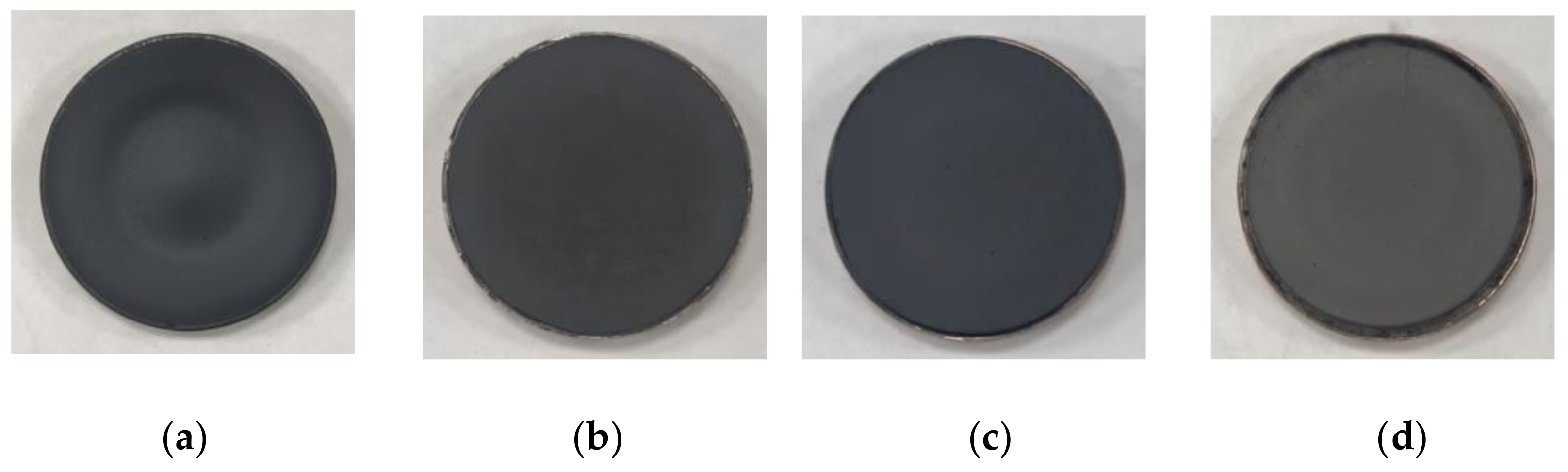
| NiO | - | 50.73 | 49.27 | Ni1.03O (denoted as Film A) |
| LiNiO 5 | 6.59 | 39.53 | 53.88 | Li0.12Ni0.73O (denoted as Film B) |
| LiNiO 10 | 9.39 | 33.11 | 57.5 | Li0.16Ni0.58O (denoted as Film C) |
| LiNiO 15 | 13.85 | 23.27 | 62.88 | Li0.22Ni0.37O (denoted as Film D) |
| Film | Bleaching Transmittance (Tb, %) | Coloring Transmittance (Tc, %) | Transmittance Change (ΔT, %) | Intercalation Charge (Q, mC/cm2) | Optical Density (ΔOD) | Coloration Efficiency (η, cm2/C) |
|---|---|---|---|---|---|---|
| Film A | 74.1 | 38.2 | 35.9 | 11.39 | 0.29 | 25.4 |
| Film B | 74.4 | 32.9 | 41.5 | 11.70 | 0.35 | 29.9 |
| Film C | 75.9 | 31.8 | 44.1 | 11.93 | 0.38 | 31.8 |
| Film D | 73.6 | 34.2 | 39.4 | 12.45 | 0.33 | 26.5 |
© 2020 by the authors. Licensee MDPI, Basel, Switzerland. This article is an open access article distributed under the terms and conditions of the Creative Commons Attribution (CC BY) license (http://creativecommons.org/licenses/by/4.0/).
Share and Cite
Chang, J.-Y.; Chen, Y.-C.; Wang, C.-M.; Chen, Y.-W. Electrochromic Properties of Li- Doped NiO Films Prepared by RF Magnetron Sputtering. Coatings 2020, 10, 87. https://doi.org/10.3390/coatings10010087
Chang J-Y, Chen Y-C, Wang C-M, Chen Y-W. Electrochromic Properties of Li- Doped NiO Films Prepared by RF Magnetron Sputtering. Coatings. 2020; 10(1):87. https://doi.org/10.3390/coatings10010087
Chicago/Turabian StyleChang, Jui-Yang, Ying-Chung Chen, Chih-Ming Wang, and You-Wei Chen. 2020. "Electrochromic Properties of Li- Doped NiO Films Prepared by RF Magnetron Sputtering" Coatings 10, no. 1: 87. https://doi.org/10.3390/coatings10010087
APA StyleChang, J.-Y., Chen, Y.-C., Wang, C.-M., & Chen, Y.-W. (2020). Electrochromic Properties of Li- Doped NiO Films Prepared by RF Magnetron Sputtering. Coatings, 10(1), 87. https://doi.org/10.3390/coatings10010087