Article

Corrosion and Wear Resistance of Fe-Based Amorphous Coatings

1
State Key Lab for Strength and Vibration of Mechanical Structures, Department of Engineering Mechanics, Xi’an Jiaotong University, Xi’an 710049, China
2
State Key Laboratory of Advanced Processing and Recycling of Non-ferrous Metal, Lanzhou University of Technology, Lanzhou 730050, China
3
Centre for Applied Dynamics Research, School of Engineering, University of Aberdeen, Aberdeen AB24 3UE, UK
*
Author to whom correspondence should be addressed.
Coatings 2020, 10(1), 73; https://doi.org/10.3390/coatings10010073
Submission received: 31 October 2019 / Revised: 31 December 2019 / Accepted: 10 January 2020 / Published: 14 January 2020
(This article belongs to the Special Issue Tribological Behavior of Functional Surface: Models and Methods)

Abstract

:
Fe-based amorphous coatings were prepared on the surface of 45 steel substrates via supersonic plasma spraying and laser cladding. The corrosion and wear behavior of the two different coatings were investigated. Compared with supersonic plasma spraying, laser cladding resulted in coatings with a relatively denser structure, lower porosity, less cracks, and a good metallurgical bond with the substrate. Thanks to these properties, coatings produced by laser cladding exhibit a higher ability to resist uniform corrosion and better friction and wear performance than plasma-sprayed coatings.

1. Introduction

Amorphous materials exhibit excellent properties compared to crystalline materials because they do not have crystal defects, such as grain boundaries and dislocations [1]. Among metallic glasses (MGs), Fe-based MGs have attracted worldwide interest since the discovery of their high strength and hardness, excellent corrosion resistance and wear resistance, and relatively low material cost [2]. However, their engineering application is limited by their brittleness at room-temperature, size impact, and limited amorphous forming ability [3,4,5]. Amorphous coatings based on Fe-based MGs systems prepared via different methods on substrates can overcome some drawbacks, especially improving corrosion resistance and wear resistance of some materials [6]. Compared with 316 stainless-steel and Ni-based super-alloys, Fe-based amorphous coatings display corrosion resistance in complex and harsh marine environments [7,8,9,10,11]. These studies clearly indicate that Fe-based amorphous coatings can provide a higher and broad resistance to both general and localized corrosion, which is promising for their applications in ships in a marine environment, in nuclear fuel containers, in the oil and gas industries, in power stations, etc. [12,13].
Fe-based amorphous coatings fabricated using the supersonic plasma spraying technology and laser cladding technology are promising materials because of their low cost, high hardness, and good abrasive wear and corrosion resistance and may thus be developed to provide both corrosion and wear protection [14]. However, Fe-based amorphous coatings prepared via these two methods have different properties. It has been found that the thickness of Fe-based amorphous coatings prepared via plasma spraying can reach 200 μm, the bonding strength can be 60 MPa, and the porosity, related to the flow of argon during spraying, can be 2%–3% [15,16,17]. Laser cladding as a method to prepare amorphous coating is characterized by laser energy concentration, low heat input, and rapid melting and cooling. It has been shown that laser cladding produces coatings with a complete amorphous structure in the middle of the cladding layer, hardness of 1270 HV, and good corrosion resistance. As the laser scanning speed increases, the cooling rate of the coating increases, and the amorphous content of the coating increases. When the scanning speed exceeds 45 mm/s, the amorphous content in the cladding layer reaches about 45% [18,19,20,21]. Ye et al. [22] used the laser cladding technology to prepare amorphous coatings on the surface of 304 stainless steel with high amorphous content. The wear resistance of the amorphous coatings was 10 times higher than that of crystalline materials.
In a previous study on corrosion and wear, some different properties of Fe-based amorphous coatings were reported. Amorphous coatings prepared via supersonic plasma spraying technology show higher amorphous content, but the bonding strength is low, and pores and microcracks are present inside the coatings, which seriously affect their application [15,16,17,23]. Preparing amorphous coatings with laser cladding can solve the problems of low bonding strength and high porosity. However, since laser cladding completely melts amorphous powders and then cools and solidifies them to form coatings, the amorphous content of the coatings is low, and thermal stress and residual stress present inside the coatings easily generate cracks during rapid cooling [24,25]. This affects the development and application of amorphous coatings.
In this paper, supersonic plasma spraying and laser cladding were used to prepare Fe-based amorphous composite coatings on the surface of 45 steel substrates. We studied the microstructure, corrosion resistance, and friction wear of the coatings and compared and analyzed the performances of the two processes. Our results provide a basic guide for their practical application.

2. Experimental Materials and Methods

The substrate material was 45 steel with gauge dimensions of 100 × 80 × 8 mm3. The composition of the 45 steel is shown in Table 1. The alloy powder was amorphous FeCrMoCB produced by Liquidmetal Company, Lake Forest, CA, USA, with a particle size of 26–70 μm. The nominal composition of the amorphous powder is shown in Table 2. The structures of the FeCrMoCB amorphous powder and the coatings were investigated via X-ray diffractometry (XRD, PHILIPS X’ Pert MPD, Amsterdam, The Netherlands) with Cu-Kα radiation. A continuous scan mode was used to scan in a 2θ range of 20°–80°. The morphologies of the samples were established via a Quanta450FEG scanning electron microscope (SEM, FEI Company, Hillsboro, OR, USA) equipped with an energy-dispersive spectroscope (EDS).
Figure 1 shows the particle size of the powder particles, and the diffuse peak (inset) represents the amorphous phase, indicating that the powder used in this experiment was completely amorphous.
Before plasma spraying, the substrate was smoothed with sandpaper, cleaned with acetone to remove oil pollution on the surface, and finally dried in air. DH-2080 supersonic plasma spraying equipment (Shanghai Dahao Dahao Company, Shanghai, China) was used for the experiment. Table 3 lists the plasma spraying parameters used in this study. After spraying, the sample was cut into a block with a size of 10 × 10 × 8 mm3.
The laser cladding heat source used a 4000 W high-power fiber-optic laser and a coaxial powder feeding method for single-layer single-pass cladding. Table 4 lists the laser cladding parameters. Argon protection was applied during the cladding process with a gas flow rate of 25 L/min. After completing the cladding, a 10 × 10 × 8 mm3 sample was cut along the laser scanning direction. The surface of each specimen was mechanically polished to a mirror finish. The morphology of the corrosion of the sample was analyzed with a Quanta450FEG SEM.
Electrochemical polarization was conducted in a three-electrode cell using a platinum counter electrode and a saturated calomel reference electrode (SCE). The specimens for the corrosion test were closely sealed with epoxy resin, leaving an end-surface (with a cross-sectional area of about 100 mm2) exposed for testing. The specimens were tested in a 3.5 wt % NaCl solution. Before testing, the testing surface of each specimen was mechanically polished to a mirror finish, then degreased in acetone, washed in distilled water, and dried in air. Electrochemical polarization curves were determined at a potential sweep rate of 2.0 mV/s in a potential range from −1.0 to 1.0 V, after holding the samples in the electrolyte at the steady open circuit potential (OCP) for a period of 600 s. Once the polarization tests were finished, the corroded samples were immediately taken out, cleaned in distilled water using ultrasonic treatment, and finally dried in air.
In this experiment, the UH4000 multifunctional hardness tester (ITM, Lake bluff, IL, USA) was used to measure the microhardness of the coatings obtained by plasma spray and laser cladding. The hardness tester used a conical diamond indenter with a loading load of 1 kgf and a loading residence time of 10 s.
Table 5 shows the parameters of the friction and wear test. The friction and wear test was carried out on the UMT-2MT universal friction and wear tester produced by CETR, USA. The friction data were determined via the reciprocating friction test method. During the test, the samples were fixed, and the friction pair reciprocated at a certain speed to achieve wear. Before the friction and wear test, the samples were cut into 19 × 12 × 5 mm3 specimens via wire cutting, carefully polished with SiC paper up to 2500 grit, and then ultrasonically cleaned with an acetone solution to remove impurities and oil stains from the surface. After the friction and wear test, the friction and wear morphology of the coatings were analyzed with a MiroXAM-800 non-contact optical profilometer (KLA-Tencor Company, Milpitas, CA, USA) and an SEM to explore the wear mechanism of the amorphous coatings.

3. Experimental Results and Analysis

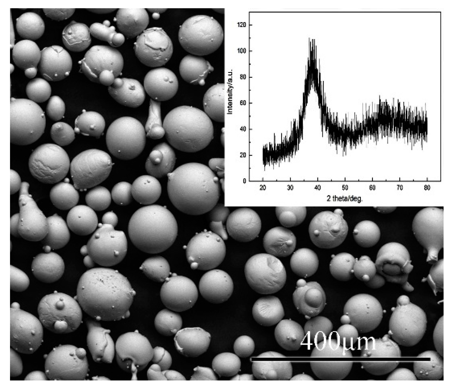
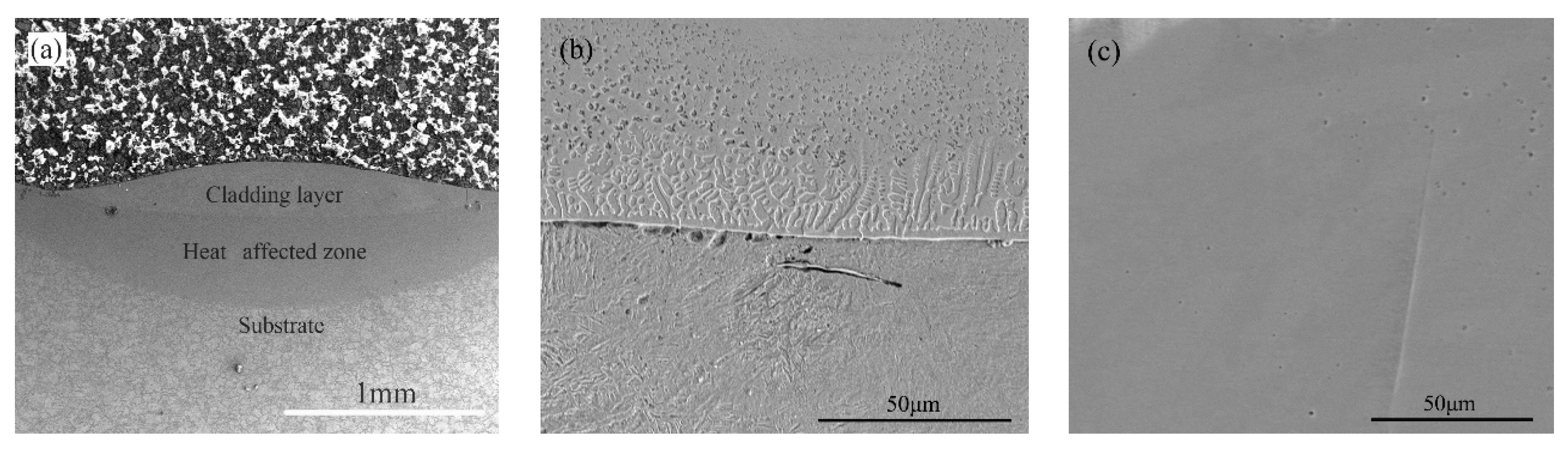
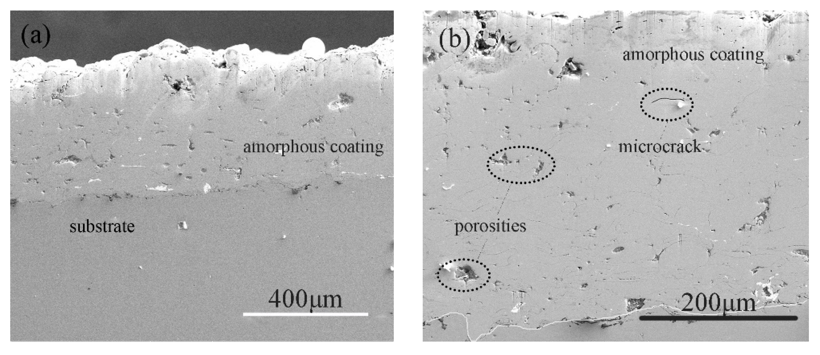
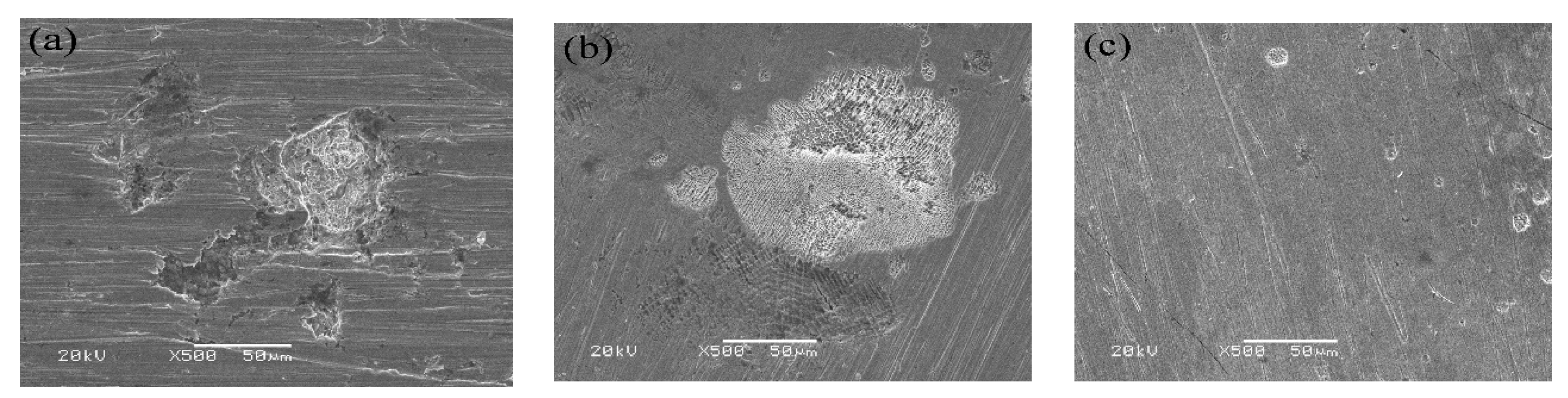
3.1. Structural Characterization of the Coatings

Figure 2a presents the cross-sectional microstructure of the laser cladding layer. It can be clearly seen that the coating consisted of a cladding layer, a heat-affected zone, and the substrate. The average thickness of the laser cladding coatings was about 150 μm. As shown, the coating did not have defects such as porosities and cracks and was well bonded to the substrate.
Figure 2b is an enlarged view of the bottom of the cladding layer in Figure 2a. It shows a dendrite region of about 20 μm at the junction of the coating and the substrate. This dendrite region is a columnar crystal that formed by propelling straight forward at a lower rate, as a consequence of the large temperature gradient between the substrate and the coating. The presence at the bottom of the coating of this typical epitaxial-growth columnar crystal region indicates that the coating and the substrate had a good metallurgical bond. According to the liquid solidification theory, a crystal growth morphology is mainly determined by the solid–liquid interface stability factor G/R (G is the temperature gradient, and R is the solidification rate). When the liquid phase begins to solidify, the temperature at the bottom of the molten pool differs greatly from the temperature of the substrate material, and the solidified structure grows along the maximum heat dissipation direction of the molten pool. Along the bottom of the molten pool to the surface of the coating, the temperature gradient G gradually decreases, and the solidification rate R gradually increases, which hampers the tendency of the columnar crystal to continue growing upward. The growth of the columnar crystal is interrupted, resulting in the formation of an equiaxed crystal region.
Figure 2c is a magnified image of the surface of the cladding layer in Figure 2a. It shows that hardly any dendritic crystal region with a finer grain size was present. This suggests that the surface of the cladding layer was still amorphous. The fast heat loss of the surface layer limited the growth of nucleation sites.
Figure 3a shows the cross-sectional morphology of a coating obtained by supersonic plasma spraying. It can be seen that the coating thickness was about 400 μm, and the coating was well formed.
Figure 3b is an enlarged view of the interface between coating and substrate. It can be observed that there was a mechanical bond between the coating and the substrate, and some pores were present at the bonding surface. A small number of unmelted particles, pores, and microcracks appeared in the coating due to the large Ar flow introduced into the air during the spraying process. On the other hand, pores and microcracks formed in a relatively loose layered structure when the particles hit the substrate at a high speed, which led to a severe splash phenomenon, so that the boundaries of some droplets could not be tightly fused together.

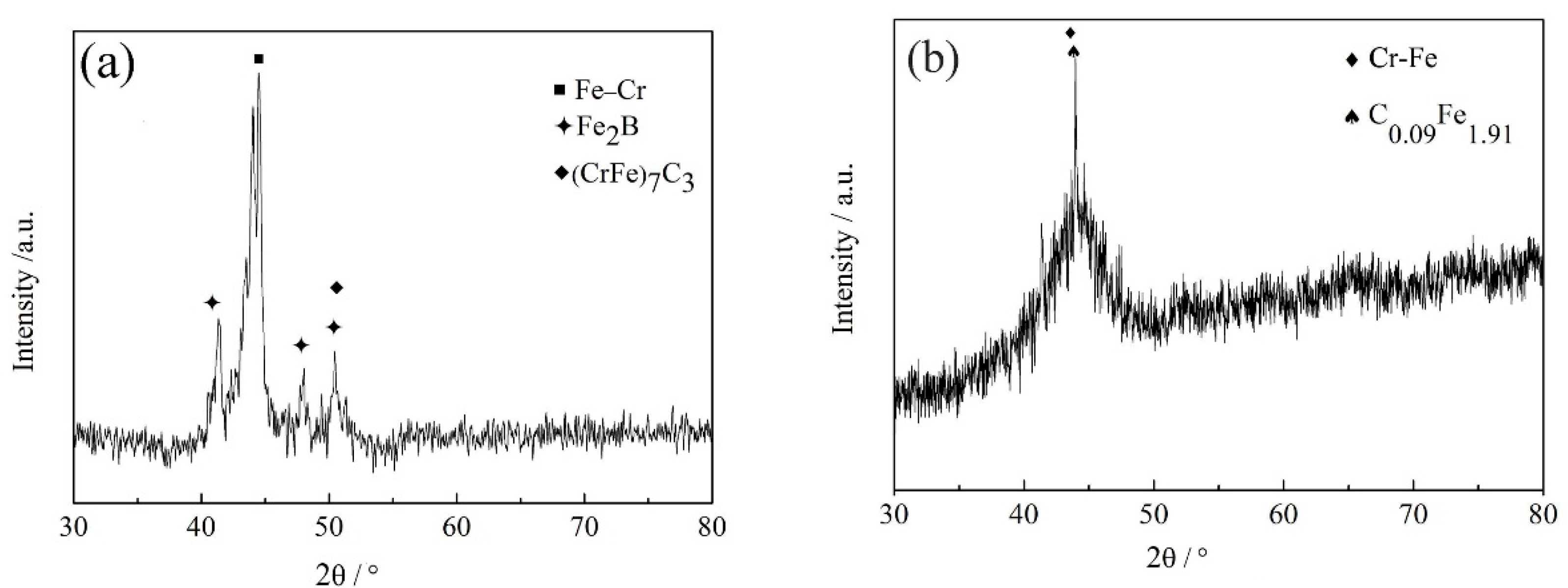
3.2. Phasse of the Coatings

Figure 4a shows the XRD pattern of the coating obtained by laser cladding. It consists of several sharp diffraction peaks appearing at approximately 40°–50°, which represent the crystalline phase, indicating that the coating contained a crystalline phase. After analyzing the results, these crystal phases appeared to consist mainly of Fe–Cr, Fe2B, (CrFe)7C3, and other compounds. These hard phases significantly increase the microhardness of the coating. Therefore, the coating was not composed of complete Fe-based amorphous materials but contained crystal phases.
Figure 4b shows the XRD pattern of the supersonic plasma-sprayed coating. It can be seen that a diffuse peak of the amorphous phase appeared between 40° and 50°, indicating that the coating had a higher amorphous content compared to the one produced by laser cladding. However, a distinct sharp peak appeared at 44°, which corresponded to a Cr–Fe and C0.09Fe1.91 compound. This could be due to the fact that the powder contained 3% of carbon, and the carbon atoms, characterized by a higher melting point than the Fe atoms, formed a compound with the Fe atoms in the coating.

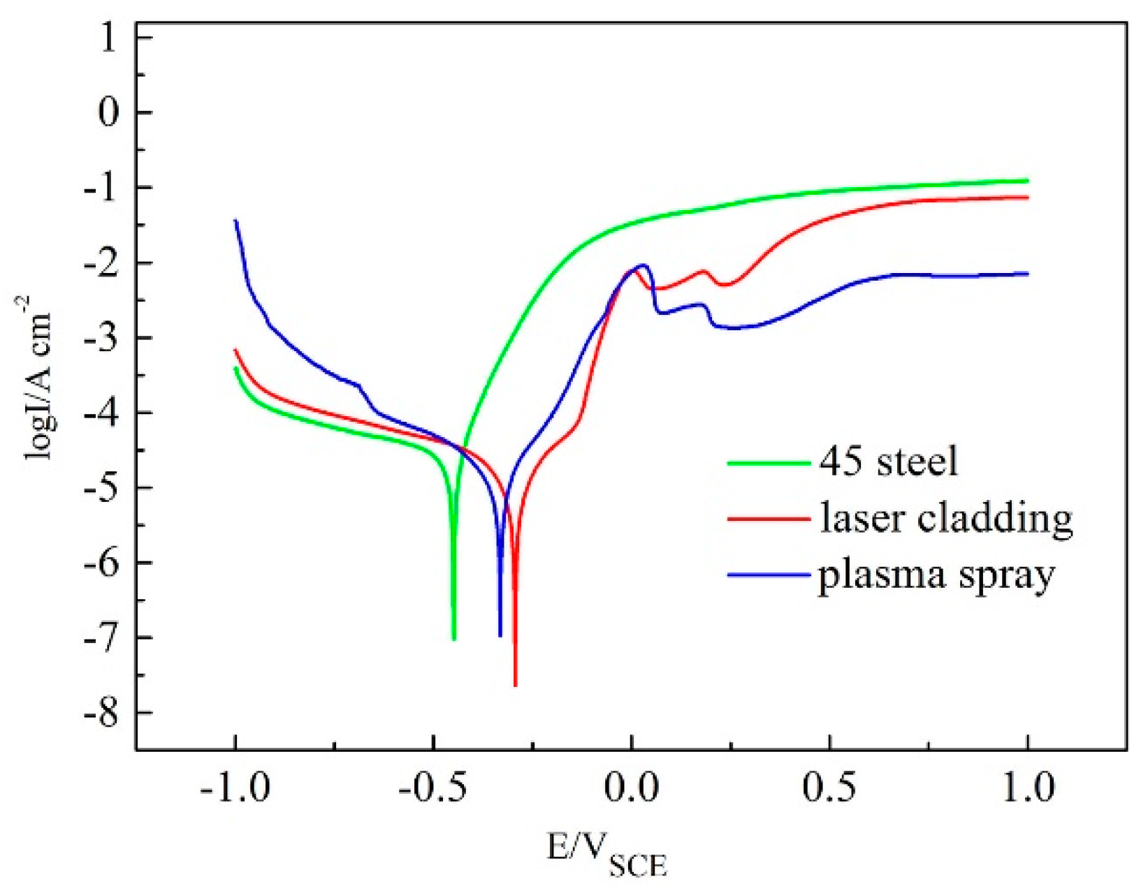
3.3. Corrosion Resistance of the Coatings

Figure 5 shows the electrochemical polarization curves of the 45 steel substrate, a coating produced by laser cladding, and a supersonic plasma-sprayed coating in a 3.5 wt % NaCl solution. Table 6 shows the fitting results of the polarization curves in Figure 6. Compared with the substrate, the corrosion potential (Ecorr) of the laser cladding-produced coating increased by about 148 mV, the corrosion potential (Ecorr) of the supersonic plasma-sprayed coating increased by about 115 mV, and the corrosion current density (Icorr) was reduced by an order of magnitude. Thus, corrosion resistance was significantly improved. Compared with supersonic plasma-sprayed coatings, coatings produced by laser cladding showed a higher corrosion potential and a smaller corrosion current density. Therefore, coatings produced by laser cladding have better corrosion resistance than supersonic plasma-sprayed coatings.
Although the amorphous content of the supersonic plasma-sprayed coatings is higher than that of the coating produced by laser cladding, the supersonic plasma-sprayed coatings contain pores and microcracks, which provides an erosion path for corrosive media and reduces the corrosion resistance performance of the coatings. The coatings produced by laser cladding have a dense structure with no cracks and other obvious defects and high corrosion resistance.
Figure 6 shows the characteristic morphologies of corrosion damages generated on the surface of the substrate and coatings. Figure 6a shows deep corrosion pits in the untreated 45 steel substrate, indicating that severe corrosion occurred on the surface of 45 steel. Compared with the 45 steel substrate, the coatings showed good corrosion resistance. Figure 6b shows the micromorphology of the surface of the supersonic plasma-sprayed coating. It can be observed that many small pores appeared in the corroded area. This suggests that the plasma-sprayed coating had a low density. Figure 6c shows the micromorphology of the surface of the coating produced by laser cladding. It can be observed that there were few pits on its surface, and the corroded area was small. This indicates that coatings produced by laser cladding have a better corrosion resistance than plasma-sprayed coatings.

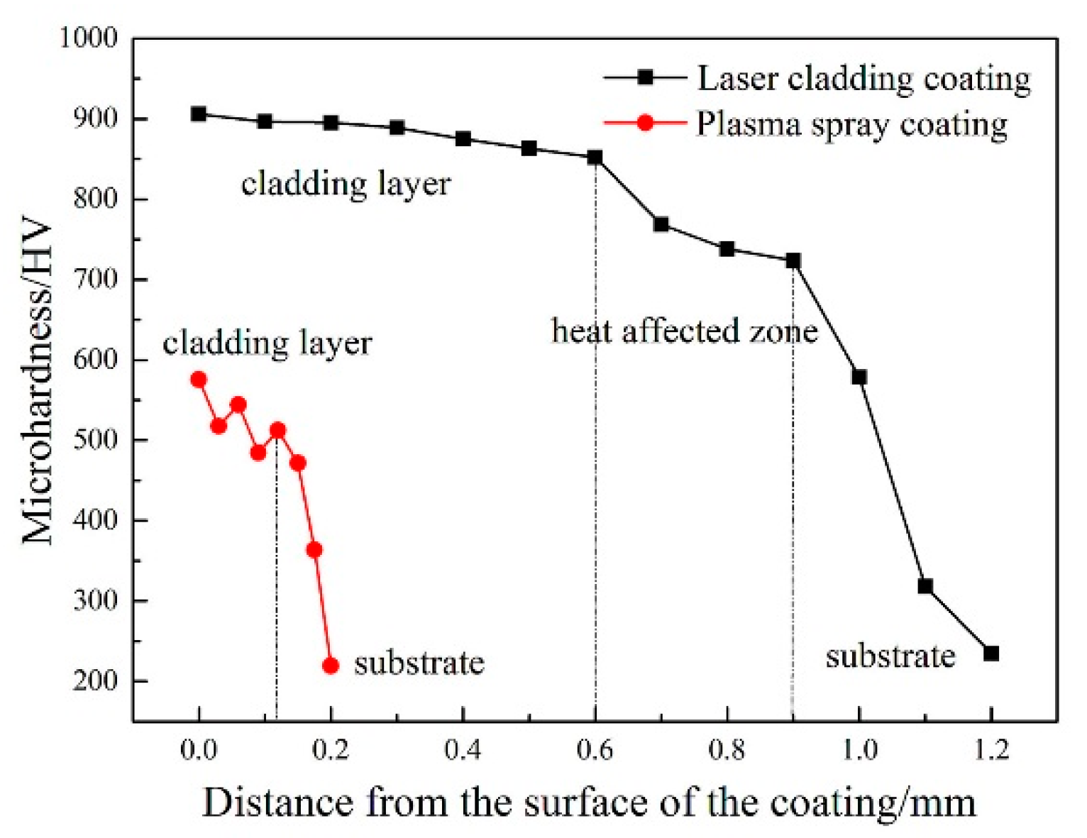
3.4. Microhardness of the Coatings

Figure 7 shows the microhardness of the laser cladding layer and supersonic plasma-sprayed coating at different depths of the coatings. It can be seen that microhardness of the laser cladding layer was significantly higher than that of the substrate and gradually decreased along the direction from the surface of the cladding layer to the substrate. The surface of the coating was relatively hard because small dendritic crystals and amorphous material coexist in this area. Near the fusion line, the hardness of the cladding layer was significantly reduced because of the penetration of the substrate into the cladding layer, which changed the composition of the cladding layer. This adversely affects the performance of coatings.
Compared with the coating produced by laser cladding, the supersonic plasma-sprayed coating has a lower hardness. This is because supersonic plasma-sprayed coatings are formed by molten or semimolten particles impacting on the surface of the substrate at high speed; this results in superimposed disc-shaped particles that combine with each other and solidify on the surface of the substrate. However, gaps remain between the particles, decreasing the hardness of the coating.

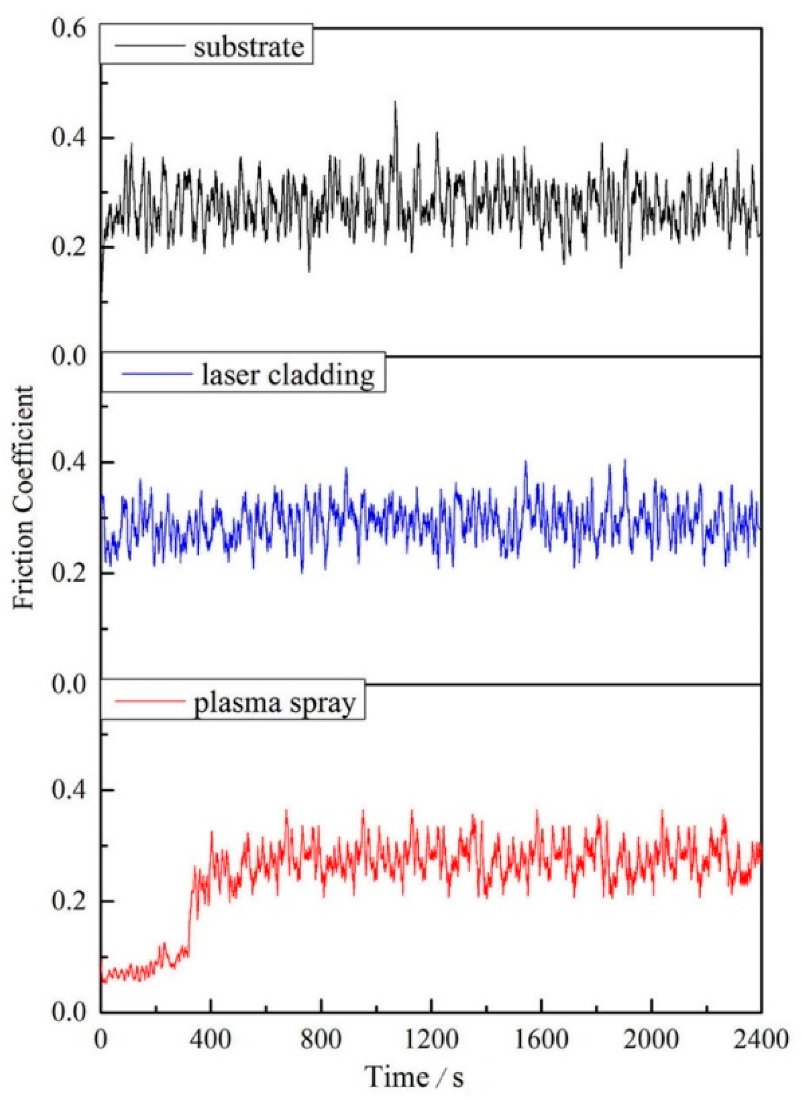
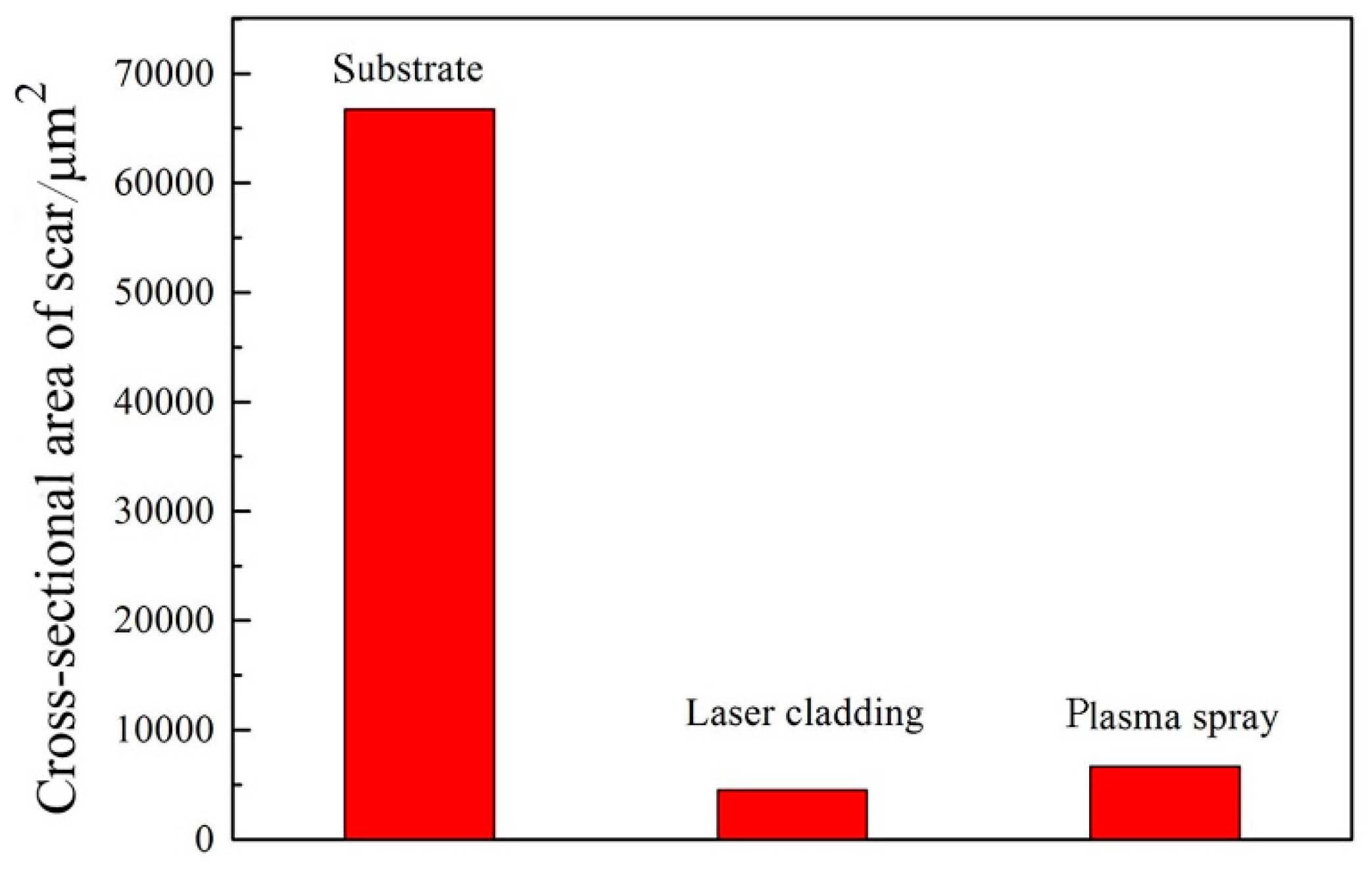
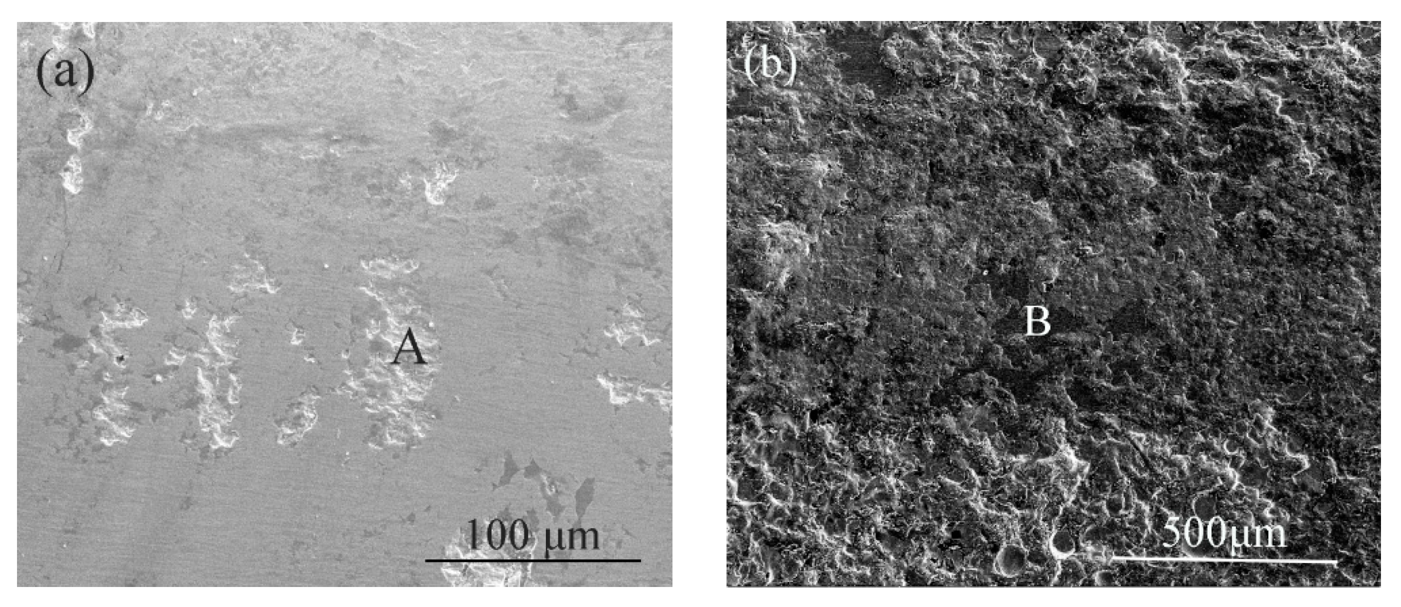
3.5. Wear Performance of the Coatings

Table 7 shows the average coefficient of friction for the 45 steel substrate, plasma-sprayed coatings, and coatings produced by laser cladding. It indicates that the average coefficients of friction of the amorphous coatings prepared by the two processes re smaller than that of the substrate. Therefore, the coatings have better wear resistance. The average coefficient of friction of the plasma-sprayed coating was lower than that of the coating produced by laser cladding because of a lower value of the coefficient of friction of the plasma-sprayed coating in the first 350 s.
Figure 8 shows the friction coefficients of the 45 steel substrate, plasma-sprayed coating, and coating produced by laser cladding. It shows that the friction coefficients of the coating produced by laser cladding and the plasma-sprayed coating were not much different from that of the substrate, but the fluctuation of the friction coefficient of the substrate was large, indicating that the amorphous composite coatings had better anti-wearing properties than the substrate. The friction coefficient curve of the coating produced by laser cladding did not show a wide range of pulsation, indicating that the coating did not show severe wear failure during the entire friction test. Therefore, coatings produced by laser cladding show excellent and stable friction and wear properties. The plasma-sprayed coating had a low coefficient of friction in the first 350 s, which then suddenly increased. The change of the friction coefficient was obvious, as indicated by the partial peeling of the coating after the first 350 s of friction.
Figure 9 shows the wear volumes of the 45 steel substrate, the coating produced by laser cladding, and the plasma-sprayed coating. Compared with the 45 steel substrate, the wear areas of the coatings prepared by the two processes were reduced by about 10 times. The wear volumes of the coatings were significantly reduced, suggesting that the abrasion resistance of the coatings was improved. The main reason for a higher wear resistance of the coating produced by laser cladding compared to the plasma-sprayed coating is that there pores and microcracks were present in the plasma-sprayed coating, which caused the coating to peel off during the friction and wear process and reduced the coating wear resistance.
Morphological observations on the wear of Fe-based amorphous coatings can provide useful information on the wear mechanisms; therefore, scanning and electron microscopy analysis of the friction and wear morphology of coatings produced by laser cladding and plasma spraying was carried out.
Figure 10 shows the wear profile of the coatings produced by laser cladding and plasma spraying. It can be seen from Figure 10a that there was a partial peeling pit in the wear region of the coating produced by laser cladding. This is because this coating contained a hard crystalline phase consisting of Fe2B and dendritic crystals. The anti-cutting ability of the coating was reduced during wear, which caused the formation of the peeling pits. In addition, there was a clear furrow in the non-flaking pit area, which was formed by the friction of the hard phase in the coating. It can be seen from Figure 10b that a large amount of flaking occurred on the surface of the plasma-sprayed coating. The reason is that this coating is a layered structure formed by particles are stacked on each other, which leave pores and microcracks inside the coating. As the wear process progresses, cracks will gradually expand, shearing the surface of the coating when they reach a critical dimension. The depth and width of the wear scar of the plasma-sprayed coating were significantly larger than those of the coating produced by laser cladding, indicating that the wear resistance of the latter is better. The reason is that the coating produced by laser cladding possesses a dense structure, characterized by metallurgical bonding between the coating and the substrate, high bonding strength, and cohesive bonding strength, in addition to amorphous and fine crystalline phases in its interior. These crystals promote fine-grain strengthening and dispersion strengthening. These factors improve the wear resistance of the coating produced by laser cladding.

4. Conclusions

Fe-based amorphous coatings produced by laser cladding and plasma-spraying were analyzed. Fe-based amorphous coating prepared by laser cladding presented better qualities than plasma-sprayed coatings.
The electrochemical behaviors of the coatings produced by laser cladding and plasma spraying in a 3.5 wt % NaCl solution were studied through electrochemical polarization. It was shown that Fe-based amorphous coatings prepared via the two processes have higher corrosion resistance than the 45 steel substrate, and the corrosion resistance of the coatings produced by laser cladding is superior to that of plasma-sprayed coatings. It was found that the corroded region in the plasma-sprayed coatings exposed many small pores, indicating that these coatings are not dense. Additionally, the supersonic plasma-sprayed coatings contain pores and microcracks, which affect their corrosion resistance. In contrast, the structure of coatings produced by laser cladding is dense and can thus protect the substrate from corrosive media.
The friction and wear properties of the coatings produced by laser cladding and plasma spraying were measured to analyze the friction coefficients and wear performances of the coatings. The wear resistances of Fe-based amorphous coatings prepared via the two processes were higher than that of the 45 steel substrate. The wear resistance of coatings produced by laser cladding is better than that of the plasma-sprayed coatings because the former are dense and contain several hard phases. In addition plasma-sprayed coatings more easily peel off during friction, because they form a mechanical bond with the substrate and have a layered structure. In contrast, coatings produced by laser cladding do not have many defects, have a dense structure, and contain some crystalline phases, all properties that improve their friction and wear resistance.

Author Contributions

Conceptualization, G.L. and Y.S.; Validation, G.L., Y.G., C.L., Y.S., Y.Z. and S.K.; Investigation, G.L. and Y.S.; Resources, G.L., Y.S., Y.Z., and S.K.; Data Curation, G.L. and Y.S.; Writing—Original Draft Preparation, Y.G., C.L. and G.L.; Writing—Review and Editing, G.L., Y.G. and C.L.; Supervision, G.L.; Project Administration, Y.S.; Funding Acquisition, G.L., Y.S., Y.Z. and S.K. All authors have read and agreed to the published version of the manuscript.

Funding

This work was supported by NSFC (Nos. 51961022, 51675256, 51661017, 51571105), China Postdoctoral Science Foundation (No. 2017M623153), and Basic Research of Gansu Province (No. 17JR5RA107).

Acknowledgments

Guang Li acknowledges the support from China Scholarship Council.

Conflicts of Interest

The authors declare no conflict of interest.

References

  1. Inoue, A. Stabilization and high strain-rate superplasticity of metallic supercooled liquid. Mater. Sci. Eng. A 1999, 267, 171–183. [Google Scholar] [CrossRef]
  2. Trexler, M.M.; Thadhani, N.N. Mechanical properties of bulk metallic glasses. Prog. Mater. Sci. 2010, 55, 759–839. [Google Scholar] [CrossRef]
  3. Gu, X.; Poon, S.J.; Shiflet, G.J. Mechanical properties of iron-based bulk metallic glasses. J. Mater. Res. 2007, 22, 344–351. [Google Scholar] [CrossRef]
  4. Gu, X.; Poon, S.J.; Shiflet, G.J.; Widom, M. Ductility improvement of amorphous steels: Roles of shear modulus and electronic structure. Acta Mater. 2008, 56, 88–94. [Google Scholar] [CrossRef]
  5. Keryvin, V.; Hoang, V.; Shen, J. Hardness, toughness, brittleness and cracking systems in an iron-based bulk metallic glass by indentation. Intermetallics 2009, 17, 211–217. [Google Scholar] [CrossRef]
  6. Inoue, A.; Kong, F.; Zhu, S.; Shalaan, E.-S.; Al-Marzouki, F. Production methods and properties of engineering glassy alloys and composites. Intermetallics 2015, 58, 20–30. [Google Scholar] [CrossRef]
  7. Zhou, H.; Zhang, C.; Wang, W.; Yasir, M.; Liu, L. Microstructure and mechanical properties of Fe-based amorphous composite coatings reinforced by stainless steel powders. J. Mater. Technol. 2015, 31, 43–47. [Google Scholar] [CrossRef]
  8. Zhu, Y.; Li, Z.; Li, R.; Li, M.; Daze, X.; Feng, K.; Wu, Y. Microstructure and property of Fe–Co–B–Si–C–Nb amorphous composite coating fabricated by laser cladding process. Appl. Surf. Sci. 2013, 280, 50–54. [Google Scholar] [CrossRef]
  9. Farmer, J.; Haslam, J.; Day, S.; Lian, T.; Saw, C.; Hailey, P.; Choi, J.-S.; Rebak, R.; Yang, N.; Payer, J.; et al. Corrosion resistance of thermally sprayed high-boron iron-based amorphous-metal coatings: Fe49.7Cr17.7Mn1.9Mo7.4W1.6B15.2C3.8Si2.4. J. Mater. Res. 2007, 22, 2297–2311. [Google Scholar] [CrossRef]
  10. Zhang, S.; Zhang, W.; Wang, S.; Gu, X.; Wang, J. Characterisation of three-dimensional porosity in an Fe-based amorphous coating and its correlation with corrosion behaviour. Corros. Sci. 2015, 93, 211–221. [Google Scholar] [CrossRef]
  11. Zhang, C.; Zhang, Z.-W.; Chen, Q.; Liu, L. Effect of hydrostatic pressure on the corrosion behavior of HVOF-sprayed Fe-based amorphous coating. J. Alloy. Compd. 2018, 758, 108–115. [Google Scholar] [CrossRef]
  12. Nie, G.M.; Huang, C.; Li, B.; Zhong, J.; Wang, S. Fabrication and application status of Fe-based amorphous alloy coatings. Surf. Technol. 2017, 46, 18–26. [Google Scholar]
  13. Zhang, C.; Guo, R.; Yang, Y.; Wu, Y.; Liu, L. Influence of the size of spraying powders on the microstructure and corrosion resistance of Fe-based amorphous coating. Electrochim. Acta 2011, 56, 6380–6388. [Google Scholar] [CrossRef]
  14. Stoica, M.; Eckert, J.; Roth, S.; Zhang, Z.; Schultz, L.; Wang, W. Mechanical behavior of Fe65.5Cr4Mo4Ga4P12C5B5.5 bulk metallic glass. Intermetallics 2005, 13, 764–769. [Google Scholar] [CrossRef]
  15. Zhou, Z.; Wang, L.; He, D.Y.; Wang, F.C.; Liu, Y.B. Microstructure and electrochemical behavior of Fe-based amorphous metallic coatings fabricated by atmospheric plasma spraying. J. Therm. Spray Technol. 2011, 20, 344–350. [Google Scholar] [CrossRef]
  16. Kobayashi, A.; Yano, S.; Kimura, H.; Inoue, A. Fe-based metallic glass coatings produced by smart plasma spraying process. Mater. Sci. Eng. B 2008, 148, 110–113. [Google Scholar] [CrossRef]
  17. Zhou, Y.-Y.; Ma, G.-Z.; Wang, H.-D.; Li, G.-L.; Chen, S.-Y.; Wang, H.-J.; Liu, M. Fabrication and characterization of supersonic plasma sprayed Fe-based amorphous metallic coatings. Mater. Des. 2016, 110, 332–339. [Google Scholar] [CrossRef]
  18. Zhu, Y.; Li, Z.; Li, R.; Li, M.; Feng, K.; Wu, Y.; Wada, T.; Kato, H. High power diode laser cladding of Fe–Co–B–Si–C–Nb amorphous coating: Layered microstructure and properties. Surf. Coat. Technol. 2013, 235, 699–705. [Google Scholar] [CrossRef]
  19. Katakam, S.; Kumar, V.; Santhanakrishnan, S.; Rajamure, R.; Samimi, P.; Dahotre, N.B. Laser assisted Fe-based bulk amorphous coating: Thermal effects and corrosion. J. Alloy. Compd. 2014, 604, 266–272. [Google Scholar] [CrossRef]
  20. Mojaver, R.; Mojtahedi, F.; Shahverdi, H.R.; Torkamany, M.J. Study on feasibility of producing an amorphous surface layer of Fe49Cr18Mo7B16C4Nb3 by pulsed Nd:YAG laser surface melting. Appl. Surf. Sci. 2013, 264, 176–183. [Google Scholar] [CrossRef]
  21. Wu, X.; Hong, Y. Fe-based thick amorphous-alloy coating by laser cladding. Surf. Coat. Technol. 2001, 141, 141–144. [Google Scholar] [CrossRef]
  22. Ye, X.; Shin, Y.C. Synthesis and characterization of Fe-based amorphous composite by laser direct deposition. Surf. Coat. Technol. 2014, 239, 34–40. [Google Scholar] [CrossRef]
  23. Koga, G.; Schulz, R.; Savoie, S.; Nascimento, A.; Drolet, Y.; Bolfarini, C.; Kiminami, C.; Botta, W. Microstructure and wear behavior of Fe-based amorphous HVOF coatings produced from commercial precursors. Surf. Coat. Technol. 2017, 309, 938–944. [Google Scholar] [CrossRef]
  24. Lu, Y.; Huang, G.; Wang, Y.; Li, H.; Qin, Z.; Lu, X. Crack-free Fe-based amorphous coating synthesized by laser cladding. Mater. Lett. 2017, 210, 46–50. [Google Scholar] [CrossRef]
  25. Chew, Y.; Pang, J.H.L.; Bi, G.; Song, B. Thermo-mechanical model for simulating laser cladding induced residual stresses with single and multiple clad beads. J. Mater. Process. Technol. 2015, 224, 89–101. [Google Scholar] [CrossRef]
Figure 1. Typical SEM image and XRD analysis (inset) of FeCrMoCB amorphous metallic alloy powder.
Coatings 10 00073 g001
Figure 2. Microstructure of a coating produced by laser cladding: (a) Morphology of the cladding cross section; (b) microstructure of the bottom of the cladding layer; (c) microstructure of the surface of the cladding layer.
Coatings 10 00073 g002
Figure 3. Microstructure of a coating produced by supersonic plasma spraying: (a) Morphology of a cross section of the plasma-sprayed coating; (b) magnified view of the coating.
Coatings 10 00073 g003
Figure 4. XRD diagram of the coatings. Coatings produced by (a) laser cladding; (b) supersonic plasma spraying.
Coatings 10 00073 g004
Figure 5. Polarization curves of the 45 steel substrate and the coatings produced by laser cladding and supersonic plasma spraying.
Coatings 10 00073 g005
Figure 6. SEM micrographs of corrosion damages: (a) 45 steel; (b) supersonic plasma-sprayed coating; (c) coating produced by laser cladding.
Coatings 10 00073 g006
Figure 7. Microhardness of the coatings.
Coatings 10 00073 g007
Figure 8. Coefficient of friction of the 45 steel substrate, the coating produced by laser cladding, and the plasma-sprayed coating.
Coatings 10 00073 g008
Figure 9. Wear scar volumes of the 45 steel substrate, the coating produced by laser cladding, and the plasma-sprayed coating.
Coatings 10 00073 g009
Figure 10. Wear scar morphology of coatings produced by laser cladding and plasma spraying: Coating produced by (a) laser cladding; (b) plasma spraying.
Coatings 10 00073 g010
Table 1. Chemical composition of the 45 stainless-steel substrate (wt %).
ElementCSiMnPCuNiCrSFe
wt %0.440.210.530.0280.020.010.030.007Bal.
Table 2. Chemical composition of the cladding material (wt %).
ElementCrMoCBFe
wt %252033Bal.
Table 3. Plasma spraying parameters.
Argon Flow (L/min)Hydrogen Flow (L/min)Voltage (V)Current
(A)
Powder Feed (g/min)Spray Distance (mm)Spray Thickness (mm)
16020140370301200.2
Table 4. Laser cladding parameters.
Laser Wavelength
(nm)
Laser Power
(W)
Scanning Speed
(mm/s)
Spot Diameter
(mm)
Argon Flow
(L/min)
1070250020325
Table 5. Friction and wear test parameters for the analysis of Fe-based amorphous coatings.
Loading Force
(N)
Sliding Speed
(m/s)
Sliding Frequency
(Hz/s)
Sliding Total Stroke
(m)
Friction Pair
(mm)
Friction Time
(s)
250.12025052400
Table 6. Polarization parameters of substrate and coatings.
Substrate and CoatingEcorr/mVIcorr/A·cm−2
45 steel−448.51.049 × 10−4
Laser cladding-produced coating−300.83.583 × 10−5
Plasma-sprayed coating−332.85.218 × 10−5
Table 7. Average friction coefficients of the 45 steel substrate, the coating produced by laser cladding, and the plasma-sprayed coating.
45 SteelLaser Cladding CoatingPlasma-Sprayed Coating
Average Friction Coefficient0.29920.29150.2778

