Multicellular Cell Seeding on a Chip: New Design and Optimization towards Commercialization

 ,
,  ,
,  , , and
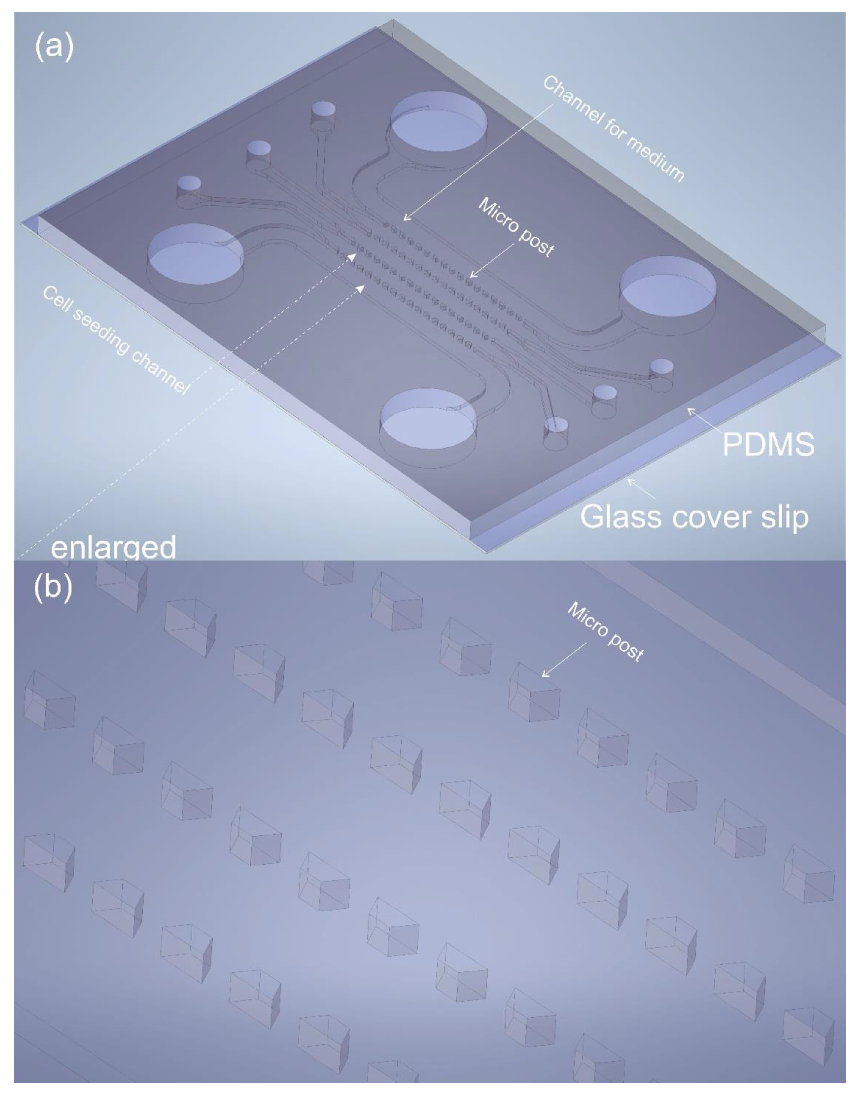
Abstract
:1. Introduction
2. Materials and Methods
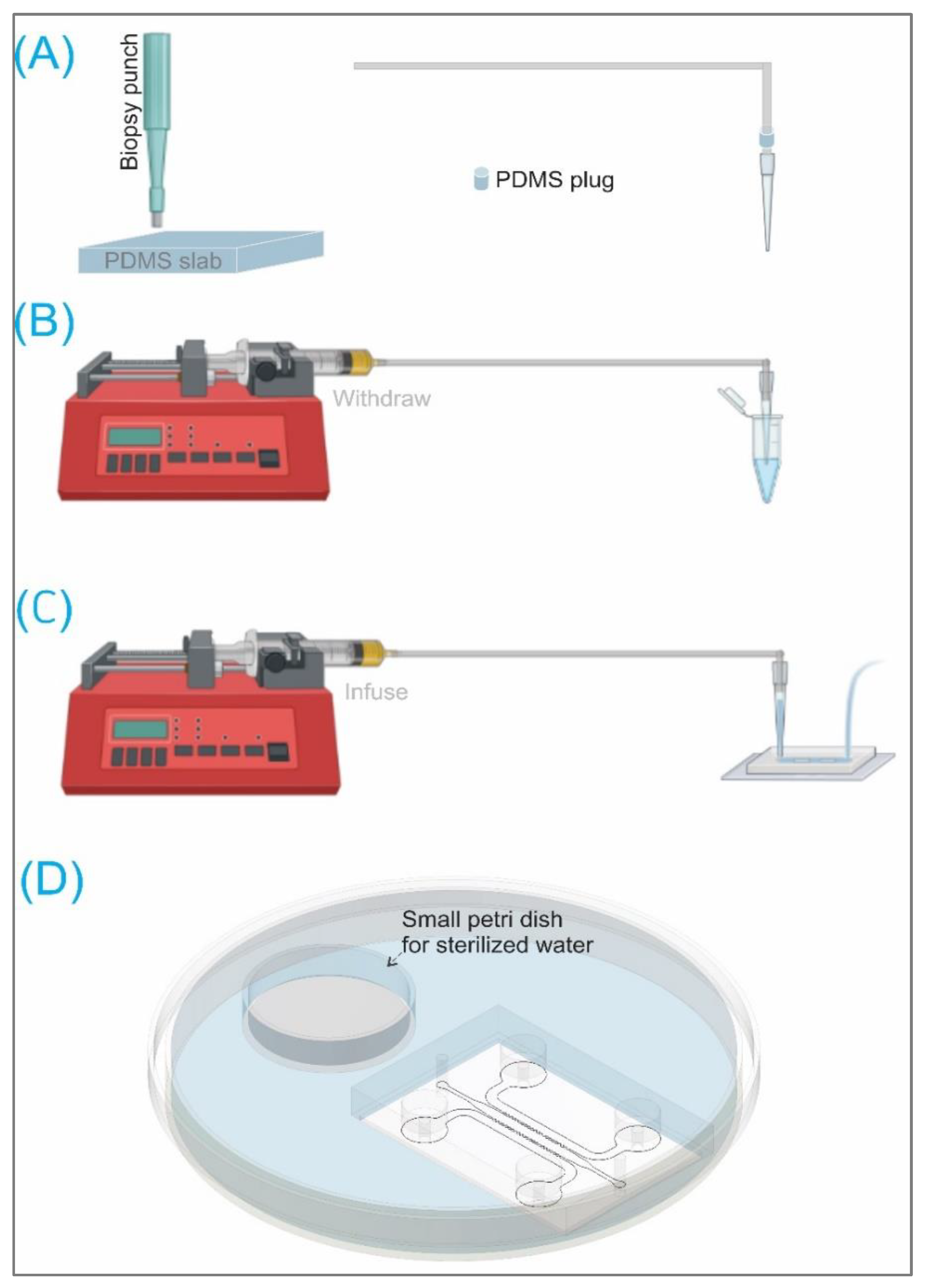
2.1. Chip Fabrication
2.2. Cell Seedings
2.3. COMSOL Multiphysics Simulation
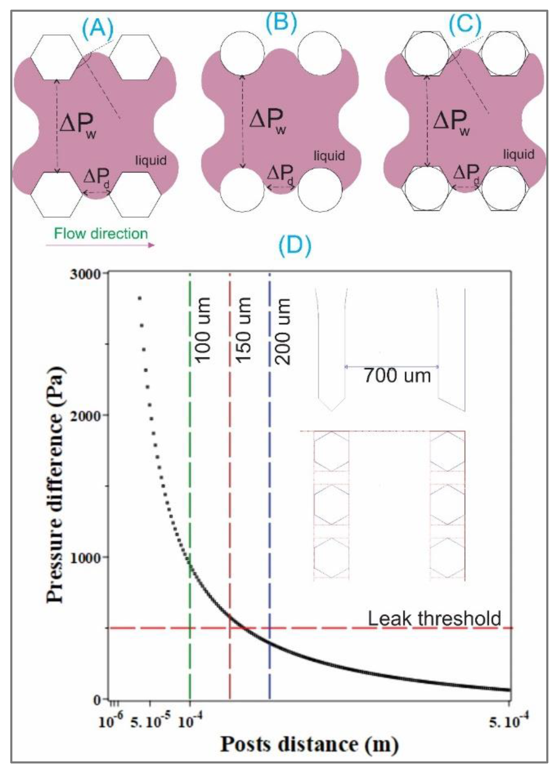
2.4. Analytical Solutions
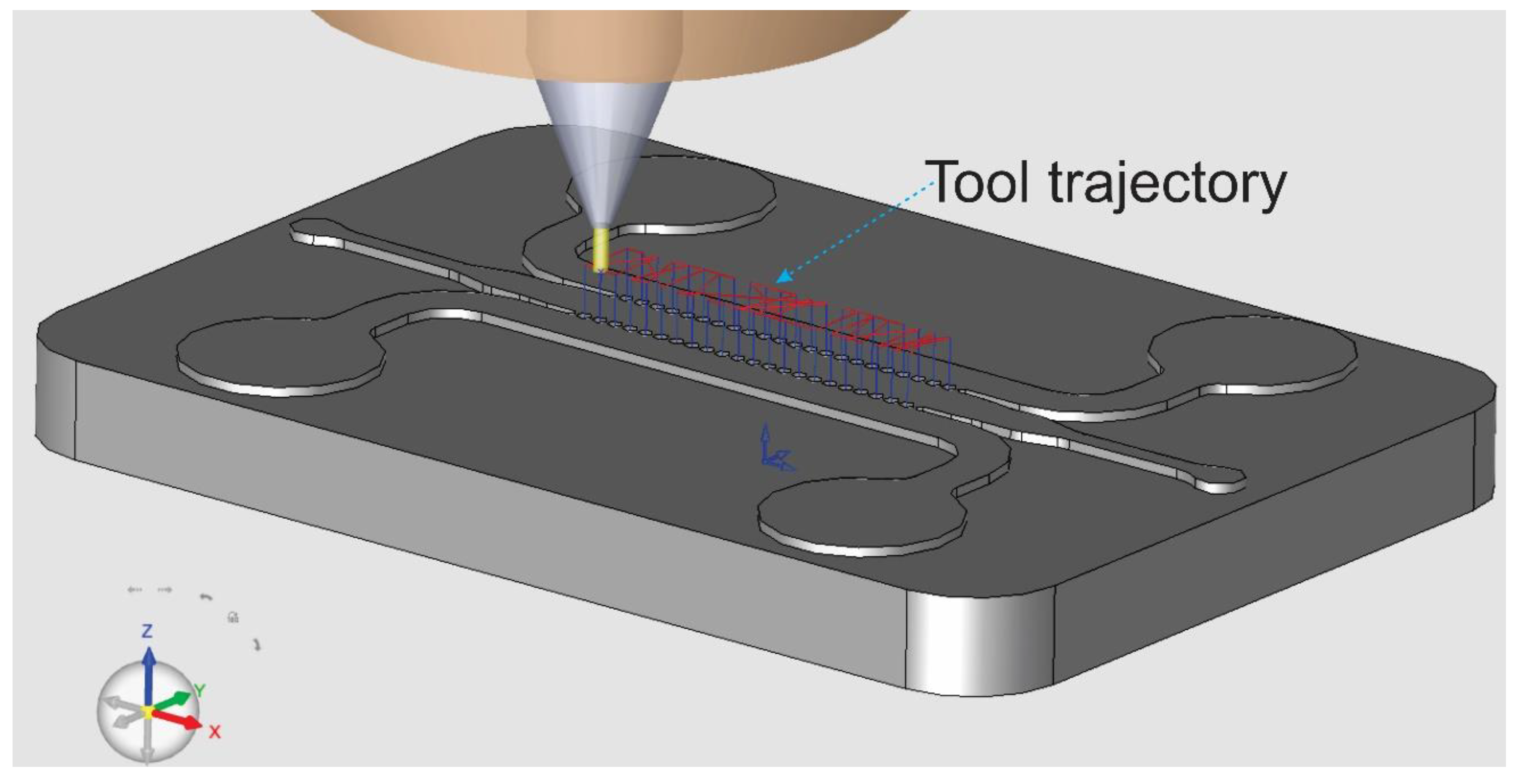
2.5. CAM Simulation
3. Results and Discussions
3.1. Analytical Solution
3.2. Chip Fabrications
3.3. COMSOL Simulations
3.4. CAM Simulations
4. Conclusions
Supplementary Materials
Author Contributions
Funding
Institutional Review Board Statement
Informed Consent Statement
Data Availability Statement
Conflicts of Interest
References
- Myers, D.R.; Sakurai, Y.; Tran, R.; Ahn, B.; Hardy, E.T.; Mannino, R.; Kita, A.; Tsai, M.; Lam, W.A. Endothelialized microfluidics for studying microvascular interactions in hematologic diseases. J. Vis. Exp. 2012, 10, 3958. [Google Scholar] [CrossRef] [PubMed] [Green Version]
- Xu, S.; Li, X.; Liu, Y.; He, P. Development and Characterization of In Vitro Microvessel Network and Quantitative Measurements of Endothelial [Ca2+]i and Nitric Oxide Production. J. Vis. Exp. 2016, 10, e54014. [Google Scholar] [CrossRef] [Green Version]
- Mannino, R.G.; Qiu, Y.; Lam, W.A. Endothelial cell culture in microfluidic devices for investigating microvascular processes. Biomicrofluidics 2018, 12, 042203. [Google Scholar] [CrossRef] [PubMed]
- Al-Hilal, T.A.; Keshavarz, A.; Kadry, H.; Lahooti, B.; Al-Obaida, A.; Ding, Z.; Li, W.; Kamm, R.; McMurtry, I.F.; Lahm, T.; et al. Pulmonary-arterial-hypertension (PAH)-on-a-chip: Fabrication, validation and application. Lab Chip 2020, 20, 3334–3345. [Google Scholar] [CrossRef] [PubMed]
- Huang, C.P.; Lu, J.; Seon, H.; Lee, A.P.; Flanagan, L.A.; Kim, H.Y.; Putnam, A.J.; Jeon, N.L. Engineering microscale cellular niches for three-dimensional multicellular co-cultures. Lab Chip 2009, 9, 1740–1748. [Google Scholar] [CrossRef] [PubMed] [Green Version]
- Kim, S.; Lee, H.; Chung, M.; Jeon, N.L. Engineering of functional, perfusable 3D microvascular networks on a chip. Lab Chip 2013, 13, 1489–1500. [Google Scholar] [CrossRef] [PubMed]
- Ko, J.; Lee, Y.; Lee, S.; Lee, S.R.; Jeon, N.L. Human Ocular Angiogenesis-Inspired Vascular Models on an Injection-Molded Microfluidic Chip. Adv. Healthc. Mater. 2019, 8, e1900328. [Google Scholar] [CrossRef] [PubMed]
- Shin, Y.; Han, S.; Jeon, J.S.; Yamamoto, K.; Zervantonakis, I.K.; Sudo, R.; Kamm, R.D.; Chung, S. Microfluidic assay for simultaneous culture of multiple cell types on surfaces or within hydrogels. Nat. Protoc. 2012, 7, 1247–1259. [Google Scholar] [CrossRef] [PubMed] [Green Version]
- Chung, S.; Sudo, R.; Mack, P.J.; Wan, C.-R.; Vickerman, V.; Kamm, R.D. Cell migration into scaffolds under co-culture conditions in a microfluidic platform. Lab Chip 2009, 9, 269–275. [Google Scholar] [CrossRef] [PubMed]
- Nguyen, T.; Chidambara, V.A.; Andreasen, S.Z.; Golabi, M.; Huynh, V.N.; Linh, Q.T.; Bang, D.D.; Wolff, A. Point-of-care devices for pathogen detections: The three most important factors to realise towards commercialization. TrAC Trends Anal. Chem. 2020, 131, 116004. [Google Scholar] [CrossRef]
- Nguyen, T.; Chidambara Vinayaka, A.; Duong Bang, D.; Wolff, A. A Complete Protocol for Rapid and Low-Cost Fabrication of Polymer Microfluidic Chips Containing Three-Dimensional Microstructures Used in Point-of-Care Devices. Micromachines 2019, 10, 624. [Google Scholar] [CrossRef] [PubMed] [Green Version]
- Hajal, C.; Offeddu, G.S.; Shin, Y.; Zhang, S.; Morozova, O.; Hickman, D.; Knutson, C.G.; Kamm, R.D. Engineered human blood-brain barrier microfluidic model for vascular permeability analyses. Nat. Protoc. 2022, 17, 95–128. [Google Scholar] [CrossRef] [PubMed]
- Hyung, S.; Lee, S.R.; Kim, J.; Kim, Y.; Kim, S.; Kim, H.N.; Jeon, N.L. A 3D disease and regeneration model of peripheral nervous system-on-a-chip. Sci. Adv. 2021, 7. [Google Scholar] [CrossRef] [PubMed]
- Farahat, W.A.; Wood, L.B.; Zervantonakis, I.K.; Schor, A.; Ong, S.; Neal, D.; Kamm, R.D.; Asada, H.H. Ensemble analysis of angiogenic growth in three-dimensional microfluidic cell cultures. PLoS ONE 2012, 7, e37333. [Google Scholar] [CrossRef] [PubMed] [Green Version]
- Ezra Tsur, E.; Zimerman, M.; Maor, I.; Elrich, A.; Nahmias, Y. Microfluidic Concentric Gradient Generator Design for High-Throughput Cell-Based Studies. Front. Bioeng. Biotechnol. 2017, 5, 21. [Google Scholar] [CrossRef] [PubMed] [Green Version]
- Manbachi, A.; Shrivastava, S.; Cioffi, M.; Chung, B.G.; Moretti, M.; Demirci, U.; Yliperttula, M.; Khademhosseini, A. Microcirculation within grooved substrates regulates cell positioning and cell docking inside microfluidic channels. Lab Chip 2008, 8, 747–754. [Google Scholar] [CrossRef] [PubMed] [Green Version]
- Cho, M.; Park, J.K. Modular 3D In Vitro Artery-Mimicking Multichannel System for Recapitulating Vascular Stenosis and Inflammation. Micromachines 2021, 12, 1528. [Google Scholar] [CrossRef] [PubMed]


Publisher’s Note: MDPI stays neutral with regard to jurisdictional claims in published maps and institutional affiliations. |
© 2022 by the authors. Licensee MDPI, Basel, Switzerland. This article is an open access article distributed under the terms and conditions of the Creative Commons Attribution (CC BY) license (https://creativecommons.org/licenses/by/4.0/).
Share and Cite
Nguyen, T.; Ho, L.; Moinuddin, S.M.; Sarkar, T.; Saha, D.; Ahsan, F. Multicellular Cell Seeding on a Chip: New Design and Optimization towards Commercialization. Biosensors 2022, 12, 587. https://doi.org/10.3390/bios12080587
Nguyen T, Ho L, Moinuddin SM, Sarkar T, Saha D, Ahsan F. Multicellular Cell Seeding on a Chip: New Design and Optimization towards Commercialization. Biosensors. 2022; 12(8):587. https://doi.org/10.3390/bios12080587
Chicago/Turabian StyleNguyen, Trieu, Linh Ho, Sakib M. Moinuddin, Tanoy Sarkar, Dipongkor Saha, and Fakhrul Ahsan. 2022. "Multicellular Cell Seeding on a Chip: New Design and Optimization towards Commercialization" Biosensors 12, no. 8: 587. https://doi.org/10.3390/bios12080587
APA StyleNguyen, T., Ho, L., Moinuddin, S. M., Sarkar, T., Saha, D., & Ahsan, F. (2022). Multicellular Cell Seeding on a Chip: New Design and Optimization towards Commercialization. Biosensors, 12(8), 587. https://doi.org/10.3390/bios12080587