Modular and Integrated Systems for Nanoparticle and Microparticle Synthesis—A Review

 ,
,  , , ,
, , , 
Abstract
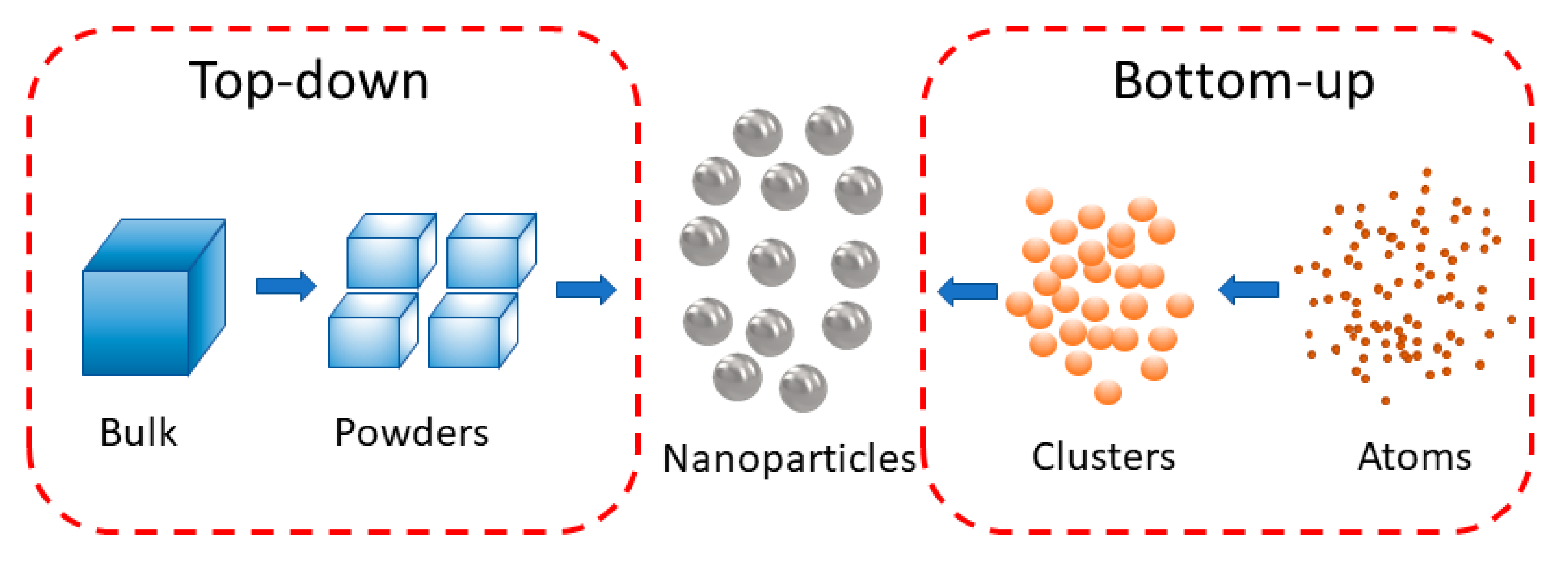
1. Introduction
2. Integrated Systems for Synthesising NPs
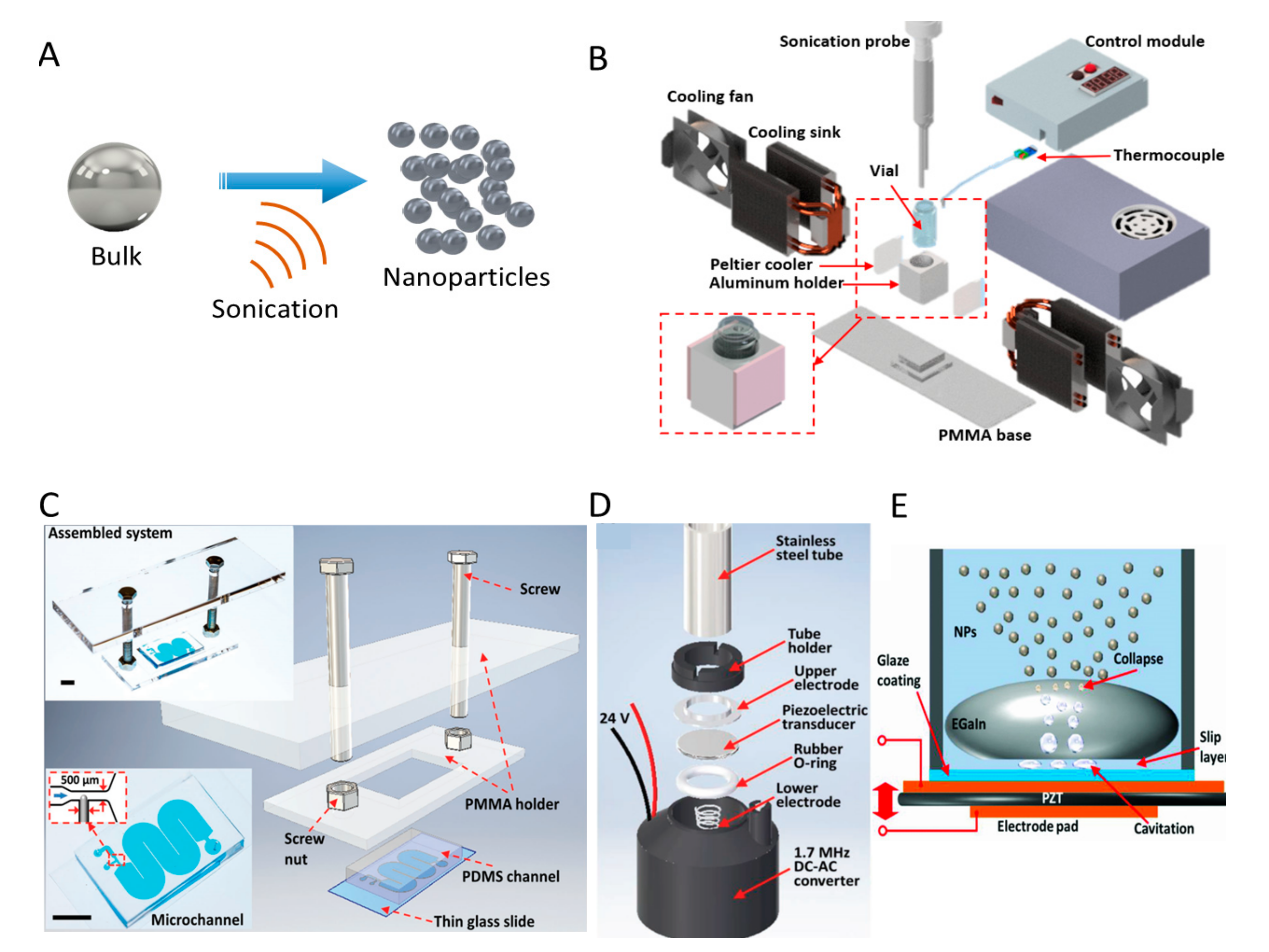
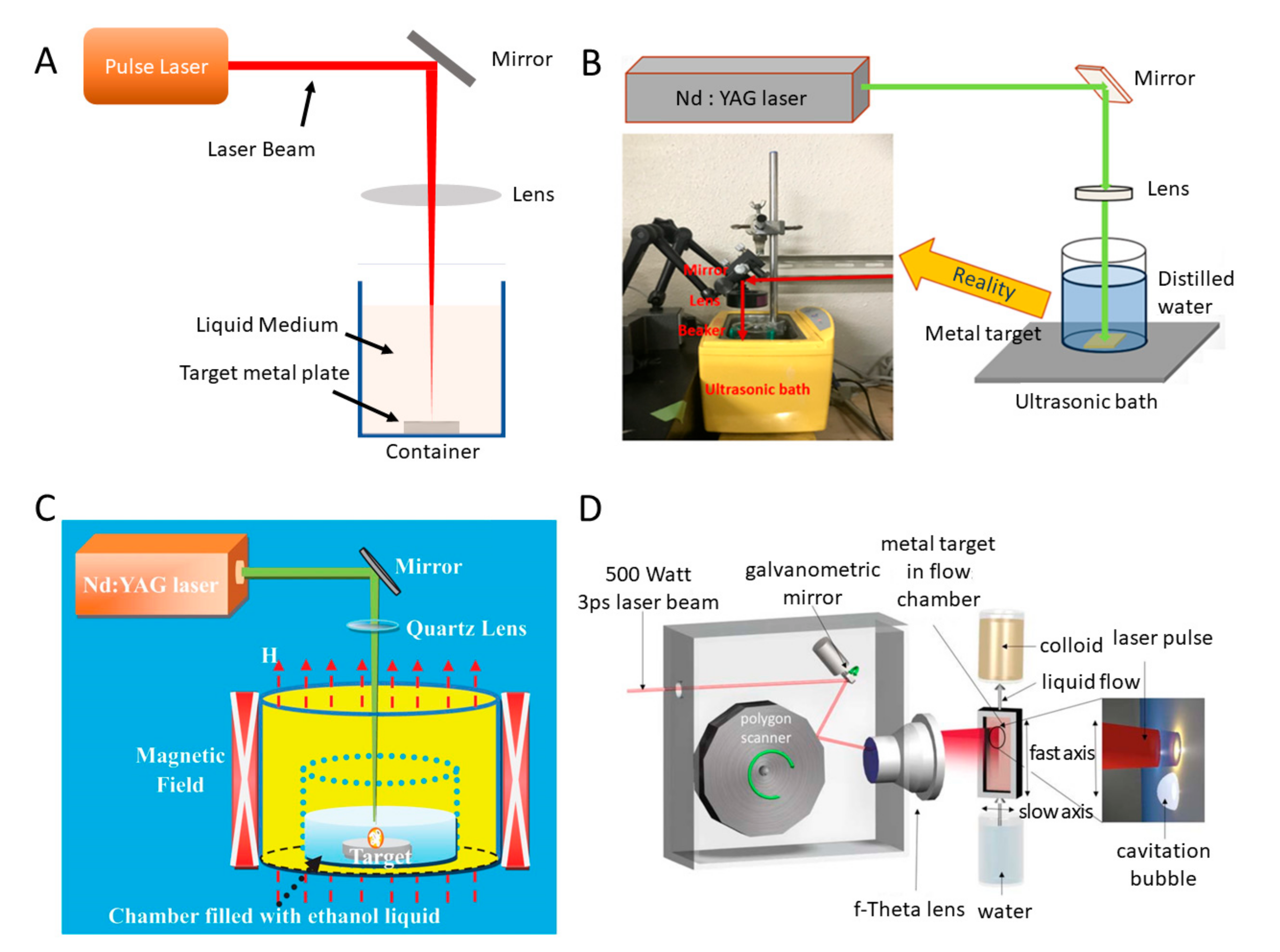
2.1. Systems Based on Top-Down Methods
2.1.1. Sonication Systems
2.1.2. Laser Ablation Systems
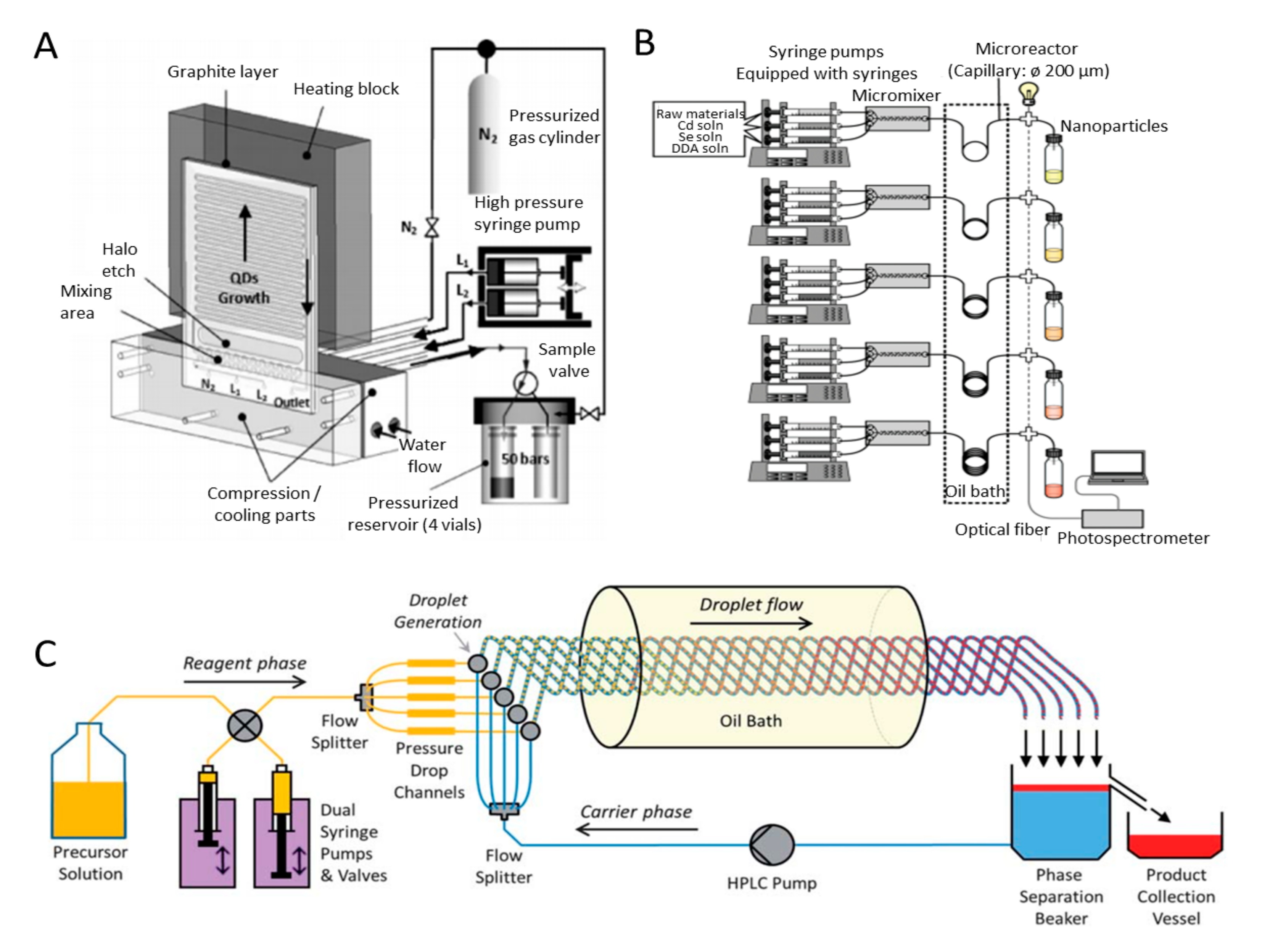
2.2. Systems Based on Bottom-Up Methods
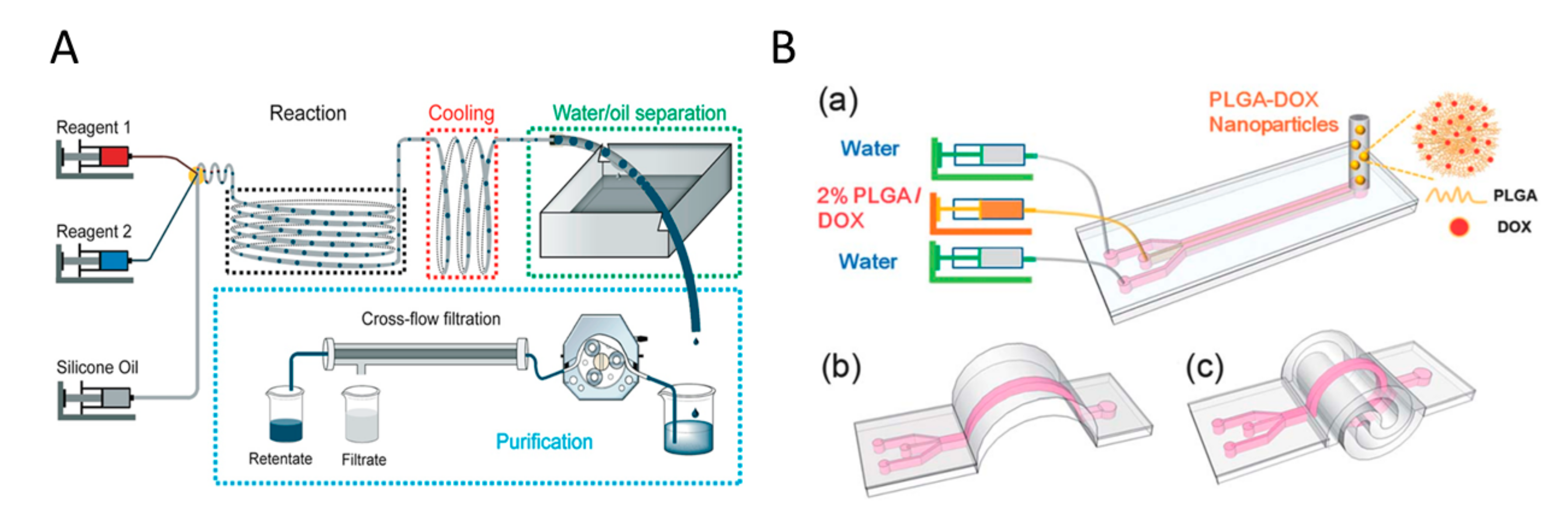
2.2.1. Microfluidic and Millifluidic Systems
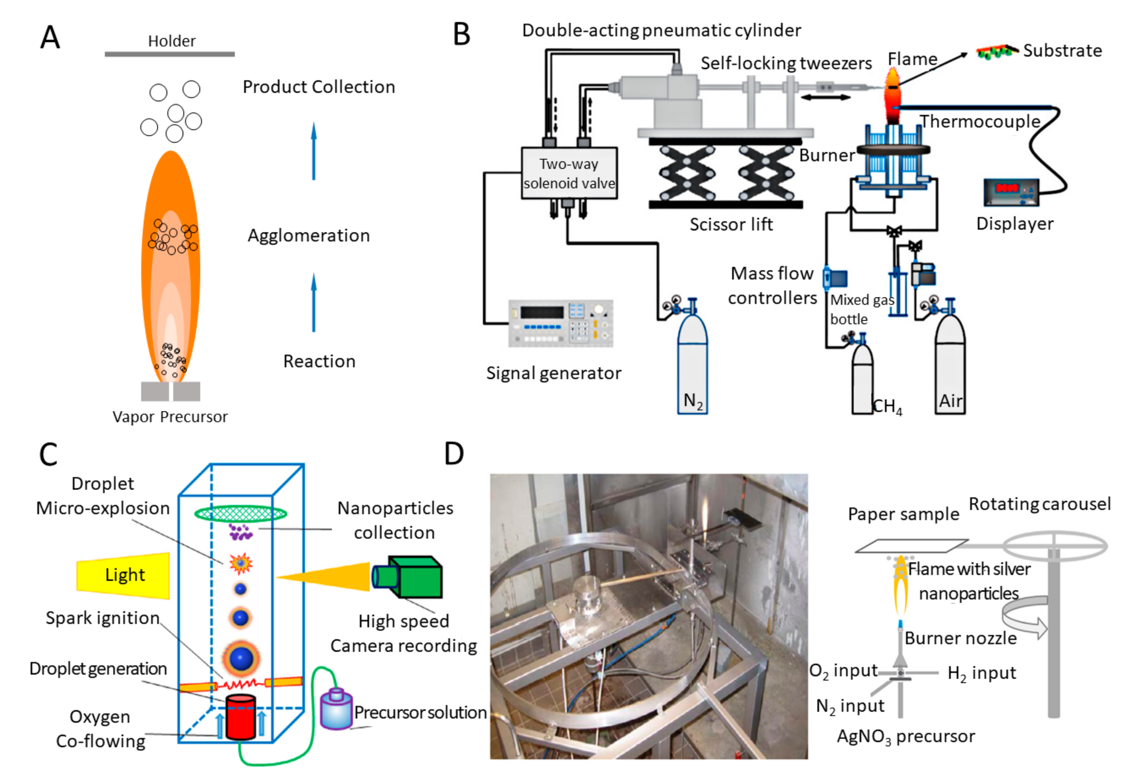
2.2.2. Flame Synthesis Systems
3. Integrated Systems for MPs Production
3.1. Microfluidic Systems
3.2. Acoustic Systems
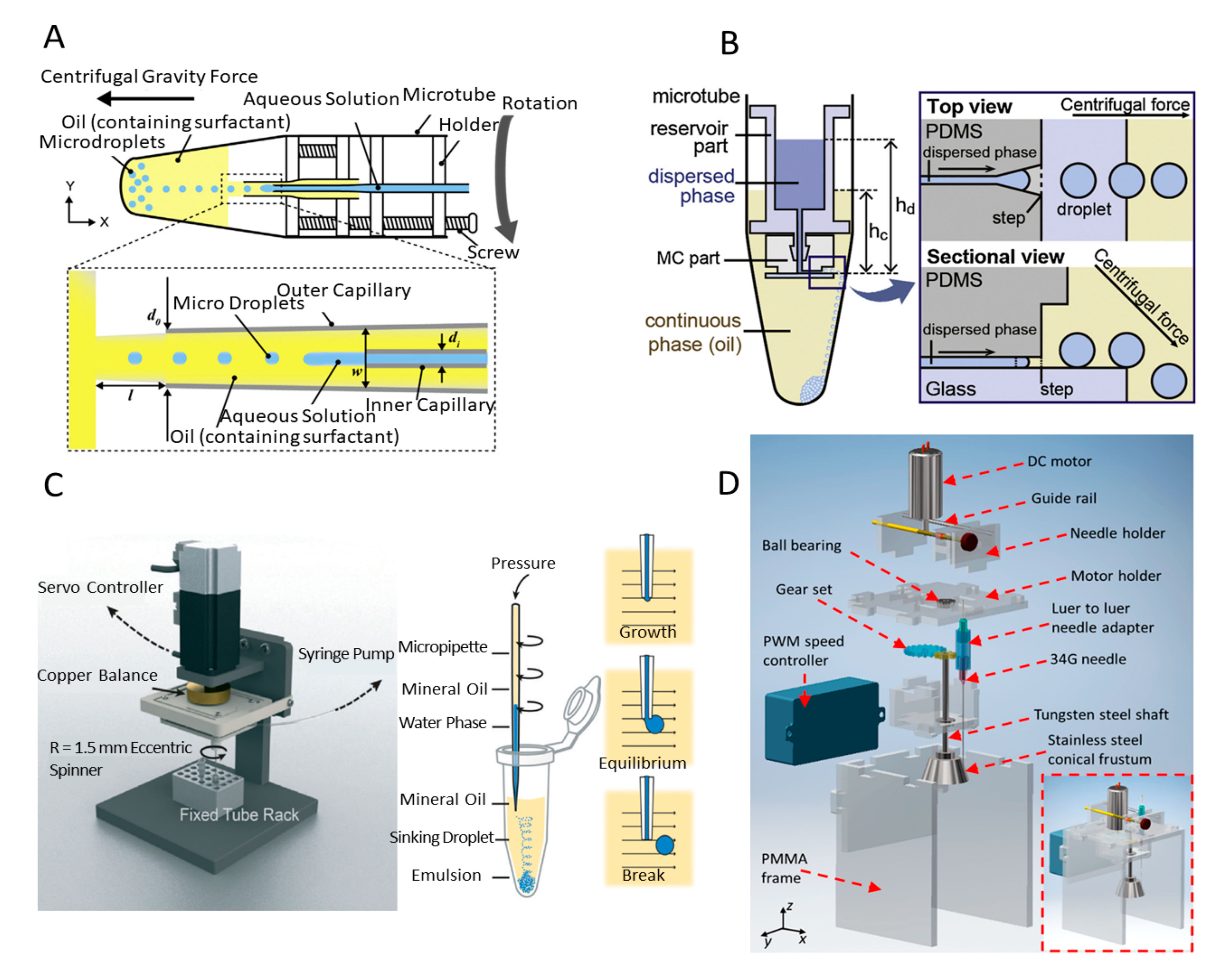
3.3. Centrifugal and Spinning Systems
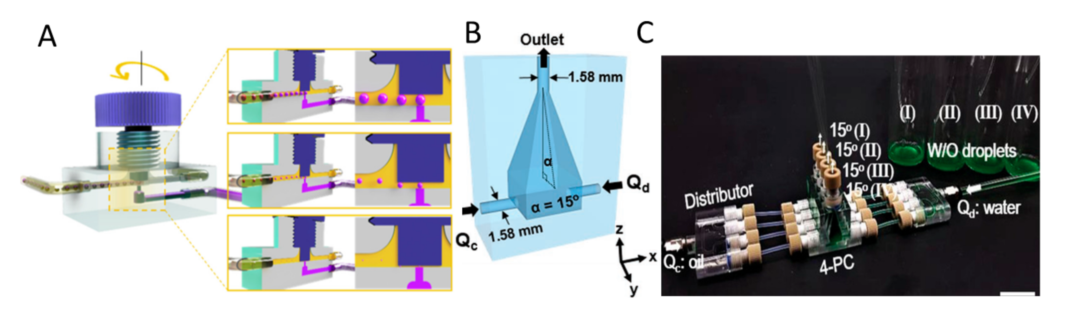
3.4. Jetting Systems

4. Conclusions and Outlook
Funding
Conflicts of Interest
References
- Singh, A.K.; Xu, Q. Synergistic Catalysis over Bimetallic Alloy Nanoparticles. Chemcatchem 2013, 5, 652–676. [Google Scholar] [CrossRef]
- Campelo, J.M.; Luna, D.; Luque, R.; Marinas, J.M.; Romero, A.A. Sustainable Preparation of Supported Metal Nanoparticles and Their Applications in Catalysis. Chemsuschem 2009, 2, 18–45. [Google Scholar] [CrossRef] [PubMed]
- Vairavapandian, D.; Vichchulada, P.; Lay, M.D. Preparation and modification of carbon nanotubes: Review of recent advances and applications in catalysis and sensing. Anal. Chim. Acta 2008, 626, 119–129. [Google Scholar] [CrossRef]
- Asadian, E.; Ghalkhani, M.; Shahrokhian, S. Electrochemical sensing based on carbon nanoparticles: A review. Sens. Actuators B Chem. 2019, 293, 183–209. [Google Scholar] [CrossRef]
- Krishna, V.D.; Wu, K.; Su, D.; Cheeran, M.C.J.; Wang, J.P.; Perez, A. Nanotechnology: Review of concepts and potential application of sensing platforms in food safety. Food Microbiol. 2018, 75, 47–54. [Google Scholar] [CrossRef]
- Moreira, A.F.; Rodrigues, C.F.; Reis, C.A.; Costa, E.C.; Correia, I.J. Gold-core silica shell nanoparticles application in imaging and therapy: A review. Microporous Mesoporous Mater. 2018, 270, 168–179. [Google Scholar] [CrossRef]
- Padmanabhan, P.; Kumar, A.; Kumar, S.; Chaudhary, R.K.; Gulyás, B. Nanoparticles in practice for molecular-imaging applications: An overview. Acta Biomater. 2016, 41, 1–16. [Google Scholar] [CrossRef]
- Daraee, H.; Eatemadi, A.; Abbasi, E.; Aval, S.F.; Kouhi, M.; Akbarzadeh, A. Application of gold nanoparticles in biomedical and drug delivery. Artif. Cells Nanomed. Biotechnol. 2016, 44, 410–422. [Google Scholar] [CrossRef]
- Elahi, N.; Kamali, M.; Baghersad, M.H. Recent biomedical applications of gold nanoparticles: A review. Talanta 2018, 184, 537–556. [Google Scholar] [CrossRef]
- Dickey, M.D. Emerging Applications of Liquid Metals Featuring Surface Oxides. Acs Appl. Mater. Interfaces 2014, 6, 18369–18379. [Google Scholar] [CrossRef]
- Khoshmanesh, K.; Tang, S.-Y.; Zhu, J.Y.; Schaefer, S.; Mitchell, A.; Kalantar-Zadeh, K.; Dickey, M.D. Liquid metal enabled microfluidics. Lab A Chip 2017, 17, 974–993. [Google Scholar] [CrossRef] [PubMed]
- Song, H.; Kim, T.; Kang, S.; Jin, H.; Lee, K.; Yoon, H.J. Ga-Based Liquid Metal Micro/Nanoparticles: Recent Advances and Applications. Small 2020, 16. [Google Scholar] [CrossRef] [PubMed]
- Ali, A.; Ahmed, S. A review on chitosan and its nanocomposites in drug delivery. Int. J. Biol. Macromol. 2018, 109, 273–286. [Google Scholar] [CrossRef]
- Yan, J.; Lu, Y.; Chen, G.; Yang, M.; Gu, Z. Advances in liquid metals for biomedical applications. Chem. Soc. Rev. 2018, 47, 2518–2533. [Google Scholar] [CrossRef]
- Wang, Q.; Yu, Y.; Liu, J. Preparations, Characteristics and Applications of the Functional Liquid Metal Materials. Adv. Eng. Mater. 2018, 20, 1700781. [Google Scholar] [CrossRef]
- Lin, Y.; Genzer, J.; Dickey, M.D. Attributes, Fabrication, and Applications of Gallium-Based Liquid Metal Particles. Adv. Sci. 2020, 7, 2000192. [Google Scholar] [CrossRef] [PubMed]
- Lee, S.H.; Jun, B.-H. Silver Nanoparticles: Synthesis and Application for Nanomedicine. Int. J. Mol. Sci. 2019, 20, 865. [Google Scholar] [CrossRef]
- Darabdhara, G.; Das, M.R.; Singh, S.P.; Rengan, A.K.; Szunerits, S.; Boukherroub, R. Ag and Au nanoparticles/reduced graphene oxide composite materials: Synthesis and application in diagnostics and therapeutics. Adv. Colloid Interface Sci. 2019, 271, 101991. [Google Scholar] [CrossRef]
- Jeyaraj, M.; Gurunathan, S.; Qasim, M.; Kang, M.-H.; Kim, J.-H. A Comprehensive Review on the Synthesis, Characterization, and Biomedical Application of Platinum Nanoparticles. Nanomaterials 2019, 9, 1719. [Google Scholar] [CrossRef]
- Azharuddin, M.; Zhu, G.H.; Das, D.; Ozgur, E.; Uzun, L.; Turner, A.P.; Patra, H.K. A repertoire of biomedical applications of noble metal nanoparticles. Chem. Commun. 2019, 55, 6964–6996. [Google Scholar] [CrossRef]
- Rafique, M.; Shaikh, A.J.; Rasheed, R.; Tahir, M.B.; Bakhat, H.F.; Rafique, M.S.; Rabbani, F. A review on synthesis, characterization and applications of copper nanoparticles using green method. Nano 2017, 12, 1750043. [Google Scholar] [CrossRef]
- Al-Hakkani, M.F. Biogenic copper nanoparticles and their applications: A review. Sn Appl. Sci. 2020, 2, 1–20. [Google Scholar] [CrossRef]
- Din, M.I.; Rehan, R. Synthesis, characterization, and applications of copper nanoparticles. Anal. Lett. 2017, 50, 50–62. [Google Scholar] [CrossRef]
- Cid, A.; Simal-Gandara, J. Synthesis, characterization, and potential applications of transition metal nanoparticles. J. Inorg. Organomet. Polym. Mater. 2020, 30, 1011–1032. [Google Scholar] [CrossRef]
- Abo-Zeid, Y.; Williams, G.R. The potential anti-infective applications of metal oxide nanoparticles: A systematic review. Wiley Interdiscip. Rev. Nanomed. Nanobiotechnol. 2020, 12, e1592. [Google Scholar] [CrossRef]
- George, J.M.; Antony, A.; Mathew, B. Metal oxide nanoparticles in electrochemical sensing and biosensing: A review. Microchim. Acta 2018, 185, 358. [Google Scholar] [CrossRef] [PubMed]
- Raghunath, A.; Perumal, E. Metal oxide nanoparticles as antimicrobial agents: A promise for the future. Int. J. Antimicrob. Agents 2017, 49, 137–152. [Google Scholar] [CrossRef]
- Wagner, A.M.; Knipe, J.M.; Orive, G.; Peppas, N.A. Quantum dots in biomedical applications. Acta Biomater. 2019, 94, 44–63. [Google Scholar] [CrossRef]
- Wu, H.-L.; Li, X.-B.; Tung, C.-H.; Wu, L.-Z. Semiconductor Quantum Dots: An Emerging Candidate for CO2 Photoreduction. Adv. Mater. 2019, 31, 1900709. [Google Scholar] [CrossRef]
- McHugh, K.J.; Jing, L.; Behrens, A.M.; Jayawardena, S.; Tang, W.; Gao, M.; Langer, R.; Jaklenec, A. Biocompatible Semiconductor Quantum Dots as Cancer Imaging Agents. Adv. Mater. 2018, 30, 1706356. [Google Scholar] [CrossRef]
- Owen, J.; Brus, L. Chemical synthesis and luminescence applications of colloidal semiconductor quantum dots. J. Am. Chem. Soc. 2017, 139, 10939–10943. [Google Scholar] [CrossRef] [PubMed]
- Boakye-Yiadom, K.O.; Kesse, S.; Opoku-Damoah, Y.; Filli, M.S.; Aquib, M.; Joelle, M.M.B.; Farooq, M.A.; Mavlyanova, R.; Raza, F.; Bavi, R. Carbon dots: Applications in bioimaging and theranostics. Int. J. Pharm. 2019, 564, 308–317. [Google Scholar] [CrossRef] [PubMed]
- Alim, S.; Vejayan, J.; Yusoff, M.M.; Kafi, A.K.M. Recent uses of carbon nanotubes & gold nanoparticles in electrochemistry with application in biosensing: A review. Biosens. Bioelectron. 2018, 121, 125–136. [Google Scholar] [CrossRef] [PubMed]
- Mazrad, Z.A.I.; Lee, K.; Chae, A.; In, I.; Lee, H.; Park, S.Y. Progress in internal/external stimuli responsive fluorescent carbon nanoparticles for theranostic and sensing applications. J. Mater. Chem. B 2018, 6, 1149–1178. [Google Scholar] [CrossRef]
- Muhulet, A.; Miculescu, F.; Voicu, S.I.; Schütt, F.; Thakur, V.K.; Mishra, Y.K. Fundamentals and scopes of doped carbon nanotubes towards energy and biosensing applications. Mater. Today Energy 2018, 9, 154–186. [Google Scholar] [CrossRef]
- Martins, C.; Sousa, F.; Araújo, F.; Sarmento, B. Functionalizing PLGA and PLGA derivatives for drug delivery and tissue regeneration applications. Adv. Healthc. Mater. 2018, 7, 1701035. [Google Scholar] [CrossRef]
- Li, J.; Rao, J.; Pu, K. Recent progress on semiconducting polymer nanoparticles for molecular imaging and cancer phototherapy. Biomaterials 2018, 155, 217–235. [Google Scholar] [CrossRef]
- Calzoni, E.; Cesaretti, A.; Polchi, A.; Di Michele, A.; Tancini, B.; Emiliani, C. Biocompatible polymer nanoparticles for drug delivery applications in cancer and neurodegenerative disorder therapies. J. Funct. Biomater. 2019, 10, 4. [Google Scholar] [CrossRef]
- Ealias, A.M.; Saravanakumar, M.P. A review on the classification, characterisation, synthesis of nanoparticles and their application. IOP Conf. Ser. Mater. Sci. Eng. 2017, 263, 032019. [Google Scholar]
- Xiao, J.; Liu, P.; Wang, C.X.; Yang, G.W. External field-assisted laser ablation in liquid: An efficient strategy for nanocrystal synthesis and nanostructure assembly. Prog. Mater. Sci. 2017, 87, 140–220. [Google Scholar] [CrossRef]
- Chan, H.-K.; Kwok, P.C.L. Production methods for nanodrug particles using the bottom-up approach. Adv. Drug Deliv. Rev. 2011, 63, 406–416. [Google Scholar] [CrossRef]
- Prow, T.W.; Grice, J.E.; Lin, L.L.; Faye, R.; Butler, M.; Becker, W.; Wurm, E.M.T.; Yoong, C.; Robertson, T.A.; Soyer, H.P.; et al. Nanoparticles and microparticles for skin drug delivery. Adv. Drug Deliv. Rev. 2011, 63, 470–491. [Google Scholar] [CrossRef]
- Wang, J.; Li, Y.; Wang, X.; Wang, J.; Tian, H.; Zhao, P.; Tian, Y.; Gu, Y.; Wang, L.; Wang, C. Droplet microfluidics for the production of microparticles and nanoparticles. Micromachines 2017, 8, 22. [Google Scholar] [CrossRef]
- Hao, N.; Nie, Y.; Zhang, J.X.J. Microfluidic synthesis of functional inorganic micro-/nanoparticles and applications in biomedical engineering. Int. Mater. Rev. 2018, 63, 461–487. [Google Scholar] [CrossRef]
- Ma, J.; Lee, S.M.-Y.; Yi, C.; Li, C.-W. Controllable synthesis of functional nanoparticles by microfluidic platforms for biomedical applications—A review. Lab A Chip 2017, 17, 209–226. [Google Scholar] [CrossRef]
- Zhang, H.; Tumarkin, E.; Sullan, R.M.A.; Walker, G.C.; Kumacheva, E. Exploring Microfluidic Routes to Microgels of Biological Polymers. Macromol. Rapid Commun. 2007, 28, 527–538. [Google Scholar] [CrossRef]
- Biswas, S.; Miller, J.T.; Li, Y.; Nandakumar, K.; Kumar, C.S. Developing a millifluidic platform for the synthesis of ultrasmall nanoclusters: Ultrasmall copper nanoclusters as a case study. Small 2012, 8, 688–698. [Google Scholar] [CrossRef] [PubMed]
- Tang, S.-Y.; Ayan, B.; Nama, N.; Bian, Y.; Lata, J.P.; Guo, X.; Huang, T.J. On-Chip Production of Size-Controllable Liquid Metal Microdroplets Using Acoustic Waves. Small 2016, 12, 3861–3869. [Google Scholar] [CrossRef]
- Chen, Z.; Fu, Y.; Zhang, F.; Liu, L.; Zhang, N.; Zhou, D.; Yang, J.; Pang, Y.; Huang, Y. Spinning micropipette liquid emulsion generator for single cell whole genome amplification. Lab A Chip 2016, 16, 4512–4516. [Google Scholar] [CrossRef]
- Choi, I.H.; Kim, J. A pneumatically driven inkjet printing system for highly viscous microdroplet formation. Micro Nano Syst. Lett. 2016, 4. [Google Scholar] [CrossRef]
- Tang, S.Y.; Qiao, R.; Yan, S.; Yuan, D.; Zhao, Q.; Yun, G.; Davis, T.P.; Li, W. Microfluidic mass production of stabilized and stealthy liquid metal nanoparticles. Small 2018, 14, 1800118. [Google Scholar] [CrossRef] [PubMed]
- Tang, S.-Y.; Joshipura, I.D.; Lin, Y.; Kalantar-Zadeh, K.; Mitchell, A.; Khoshmanesh, K.; Dickey, M.D. Liquid-Metal Microdroplets Formed Dynamically with Electrical Control of Size and Rate. Adv. Mater. 2016, 28, 604–609. [Google Scholar] [CrossRef] [PubMed]
- Zhang, W.; Ou, J.Z.; Tang, S.Y.; Sivan, V.; Yao, D.D.; Latham, K.; Khoshmanesh, K.; Mitchell, A.; O’Mullane, A.P.; Kalantar-zadeh, K. Liquid metal/metal oxide frameworks. Adv. Funct. Mater. 2014, 24, 3799–3807. [Google Scholar] [CrossRef]
- Lu, H.; Tang, S.-Y.; Dong, Z.; Liu, D.; Zhang, Y.; Zhang, C.; Yun, G.; Zhao, Q.; Kalantar-Zadeh, K.; Qiao, R. Dynamic Temperature Control System for the Optimized Production of Liquid Metal Nanoparticles. Acs Appl. Nano Mater. 2020, 3, 6905–6914. [Google Scholar] [CrossRef]
- Tang, S.Y.; Qiao, R.; Lin, Y.; Li, Y.; Zhao, Q.; Yuan, D.; Yun, G.; Guo, J.; Dickey, M.D.; Huang, T.J. Functional Liquid Metal Nanoparticles Produced by Liquid-Based Nebulization. Adv. Mater. Technol. 2019, 4, 1800420. [Google Scholar] [CrossRef]
- Sportelli, M.C.; Izzi, M.; Volpe, A.; Clemente, M.; Picca, R.A.; Ancona, A.; Lugarà, P.M.; Palazzo, G.; Cioffi, N. The Pros and Cons of the Use of Laser Ablation Synthesis for the Production of Silver Nano-Antimicrobials. J. Antibiot. 2018, 7, 67. [Google Scholar] [CrossRef]
- Asahi, T.; Mafuné, F.; Rehbock, C.; Barcikowski, S. Strategies to harvest the unique properties of laser-generated nanomaterials in biomedical and energy applications. Appl. Surf. Sci. 2015, 348, 1–3. [Google Scholar] [CrossRef]
- Wang, S.; Gao, L. Laser-driven nanomaterials and laser-enabled nanofabrication for industrial applications. In Industrial Applications of Nanomaterials; Elsevier: Amsterdam, The Netherlands, 2019; pp. 181–203. [Google Scholar]
- Hu, X.; Takada, N.; Machmudah, S.; Wahyudiono; Kanda, H.; Goto, M. Ultrasonic-Enhanced Fabrication of Metal Nanoparticles by Laser Ablation in Liquid. Ind. Eng. Chem. Res. 2020, 59, 7512–7519. [Google Scholar] [CrossRef]
- Liang, Y.; Liu, P.; Xiao, J.; Li, H.; Wang, C.; Yang, G. A general strategy for one-step fabrication of one-dimensional magnetic nanoparticle chains based on laser ablation in liquid. Laser Phys. Lett. 2014, 11, 056001. [Google Scholar] [CrossRef]
- Streubel, R.; Barcikowski, S.; Gökce, B. Continuous multigram nanoparticle synthesis by high-power, high-repetition-rate ultrafast laser ablation in liquids. Opt. Lett. 2016, 41, 1486–1489. [Google Scholar] [CrossRef]
- Yu, J.; Nan, J.; Zeng, H. Size control of nanoparticles by multiple-pulse laser ablation. Appl. Surf. Sci. 2017, 402, 330–335. [Google Scholar] [CrossRef]
- Mahdieh, M.H.; Fattahi, B. Effects of water depth and laser pulse numbers on size properties of colloidal nanoparticles prepared by nanosecond pulsed laser ablation in liquid. Opt. Laser Technol. 2015, 75, 188–196. [Google Scholar] [CrossRef]
- Kőrösi, L.; Rodio, M.; Dömötör, D.; Kovács, T.; Papp, S.; Diaspro, A.; Intartaglia, R.; Beke, S. Ultrasmall, ligand-free Ag nanoparticles with high antibacterial activity prepared by pulsed laser ablation in liquid. J. Chem. 2016, 2016, 4143560. [Google Scholar] [CrossRef]
- Herbani, Y.; Nasution, R.; Mujtahid, F.; Masse, S. Pulse laser ablation of Au, Ag, and Cu metal targets in liquid for nanoparticle production. J. Phys. Conf. Ser. 2018, 985, 012005. [Google Scholar] [CrossRef]
- Menazea, A. Femtosecond laser ablation-assisted synthesis of silver nanoparticles in organic and inorganic liquids medium and their antibacterial efficiency. Radiat. Phys. Chem. 2020, 168, 108616. [Google Scholar] [CrossRef]
- Liu, P.; Wang, C.; Chen, X.; Yang, G. Controllable fabrication and cathodoluminescence performance of high-index facets GeO2 micro-and nanocubes and spindles upon electrical-field-assisted laser ablation in liquid. J. Phys. Chem. C 2008, 112, 13450–13456. [Google Scholar] [CrossRef]
- Serkov, A.; Rakov, I.; Simakin, A.; Kuzmin, P.; Shafeev, G.; Mikhailova, G.; Antonova, L.K.; Troitskii, A.; Kuzmin, G. Influence of external magnetic field on laser-induced gold nanoparticles fragmentation. Appl. Phys. Lett. 2016, 109, 053107. [Google Scholar] [CrossRef]
- Shafeev, G.; Rakov, I.; Ayyyzhy, K.; Mikhailova, G.; Troitskii, A.; Uvarov, O. Generation of Au nanorods by laser ablation in liquid and their further elongation in external magnetic field. Appl. Surf. Sci. 2019, 466, 477–482. [Google Scholar] [CrossRef]
- Liu, P.; Liang, Y.; Lin, X.; Wang, C.; Yang, G. A general strategy to fabricate simple polyoxometalate nanostructures: Electrochemistry-assisted laser ablation in liquid. Acs Nano 2011, 5, 4748–4755. [Google Scholar] [CrossRef]
- Liang, Y.; Liu, P.; Li, H.; Yang, G. ZnMoO4 micro-and nanostructures synthesized by electrochemistry-assisted laser ablation in liquids and their optical properties. Cryst. Growth Des. 2012, 12, 4487–4493. [Google Scholar] [CrossRef]
- Liang, Y.; Liu, P.; Li, H.; Yang, G. Synthesis and characterization of copper vanadate nanostructures via electrochemistry assisted laser ablation in liquid and the optical multi-absorptions performance. CrystEngComm 2012, 14, 3291–3296. [Google Scholar] [CrossRef]
- Streubel, R.; Bendt, G.; Gökce, B. Pilot-scale synthesis of metal nanoparticles by high-speed pulsed laser ablation in liquids. Nanotechnology 2016, 27, 205602. [Google Scholar] [CrossRef] [PubMed]
- Guo, J.; Cheng, J.; Tan, H.; Sun, Q.; Yang, J.; Liu, W. Constructing a novel and high-performance liquid nanoparticle additive from a Ga-based liquid metal. Nanoscale 2020, 12, 9208–9218. [Google Scholar] [CrossRef] [PubMed]
- Palazzo, G.; Valenza, G.; Dell’Aglio, M.; Giacomo, A.D. On the stability of gold nanoparticles synthesized by laser ablation in liquids. J. Colloid Interface Sci. 2017, 489, 47–56. [Google Scholar] [CrossRef] [PubMed]
- Affandi, S.; Bidin, N. Pulse laser ablation in liquid induce gold nanoparticle production. J. Teknol. 2015, 74, 41–43. [Google Scholar] [CrossRef]
- Valverde-Alva, M.A.; García-Fernández, T.; Villagrán-Muniz, M.; Sánchez-Aké, C.; Castañeda-Guzmán, R.; Esparza-Alegría, E.; Sánchez-Valdés, C.F.; Llamazares, J.L.S.; Herrera, C.E.M. Synthesis of silver nanoparticles by laser ablation in ethanol: A pulsed photoacoustic study. Appl. Surf. Sci. 2015, 355, 341–349. [Google Scholar] [CrossRef]
- Tomko, J.; Naddeo, J.J.; Jimenez, R.; Tan, Y.; Steiner, M.; Fitz-Gerald, J.M.; Bubb, D.M.; O’Malley, S.M. Size and polydispersity trends found in gold nanoparticles synthesized by laser ablation in liquids. Phys. Chem. Chem. Phys. 2015, 17, 16327–16333. [Google Scholar] [CrossRef]
- Bharati, M.S.S.; Chandu, B.; Rao, S.V. Explosives sensing using Ag–Cu alloy nanoparticles synthesized by femtosecond laser ablation and irradiation. Rsc Adv. 2019, 9, 1517–1525. [Google Scholar] [CrossRef]
- Al-Antaki, A.H.M.; Luo, X.; Duan, X.; Lamb, R.N.; Hutchison, W.D.; Lawrance, W.; Raston, C.L. Continuous Flow Copper Laser Ablation Synthesis of Copper(I and II) Oxide Nanoparticles in Water. ACS Omega 2019, 4, 13577–13584. [Google Scholar] [CrossRef]
- Khashan, K.S.; Sulaiman, G.M.; Abdulameer, F.A. Synthesis and Antibacterial Activity of CuO Nanoparticles Suspension Induced by Laser Ablation in Liquid. Arab. J. Sci. Eng. 2016, 41, 301–310. [Google Scholar] [CrossRef]
- Mostafa, A.M.; Yousef, S.A.; Eisa, W.H.; Ewaida, M.A.; Al-Ashkar, E.A. Synthesis of cadmium oxide nanoparticles by pulsed laser ablation in liquid environment. Optik 2017, 144, 679–684. [Google Scholar] [CrossRef]
- Mostafa, A.M.; Yousef, S.A.; Eisa, W.H.; Ewaida, M.A.; Al-Ashkar, E.A. Au@CdO core/shell nanoparticles synthesized by pulsed laser ablation in Au precursor solution. Appl. Phys. A 2017, 123. [Google Scholar] [CrossRef]
- Hu, S.; Melton, C.; Mukherjee, D. A facile route for the synthesis of nanostructured oxides and hydroxides of cobalt using laser ablation synthesis in solution (LASIS). Phys. Chem. Chem. Phys. 2014, 16, 24034–24044. [Google Scholar] [CrossRef]
- Ma, R.; Kim, Y.-J.; Reddy, D.A.; Kim, T.K. Synthesis of CeO2/Pd nanocomposites by pulsed laser ablation in liquids for the reduction of 4-nitrophenol to 4-aminophenol. Ceram. Int. 2015, 41, 12432–12438. [Google Scholar] [CrossRef]
- Guo, Y.; Yang, X.; Li, G.; Dong, B.; Chen, L. Effect of ultrasonic intensification on synthesis of nano-sized particles with an impinging jet reactor. Powder Technol. 2019, 354, 218–230. [Google Scholar] [CrossRef]
- Ismail, R.A.; Sulaiman, G.M.; Abdulrahman, S.A.; Marzoog, T.R. Antibacterial activity of magnetic iron oxide nanoparticles synthesized by laser ablation in liquid. Mater. Sci. Eng. C 2015, 53, 286–297. [Google Scholar] [CrossRef]
- Pandey, B.K.; Shahi, A.K.; Shah, J.; Kotnala, R.K.; Gopal, R. Optical and magnetic properties of Fe2O3 nanoparticles synthesized by laser ablation/fragmentation technique in different liquid media. Appl. Surf. Sci. 2014, 289, 462–471. [Google Scholar] [CrossRef]
- Chrzanowska, J.; Hoffman, J.; Małolepszy, A.; Mazurkiewicz, M.; Kowalewski, T.A.; Szymanski, Z.; Stobinski, L. Synthesis of carbon nanotubes by the laser ablation method: Effect of laser wavelength. Phys. Status Solidi B Basic Solid State Phys. 2015, 252, 1860–1867. [Google Scholar] [CrossRef]
- Kazemizadeh, F.; Malekfar, R.; Parvin, P. Pulsed laser ablation synthesis of carbon nanoparticles in vacuum. J. Phys. Chem. Solids 2017, 104, 252–256. [Google Scholar] [CrossRef]
- Nightingale, A.M.; Bannock, J.H.; Krishnadasan, S.H.; O’Mahony, F.T.; Haque, S.A.; Sloan, J.; Drury, C.; McIntyre, R.; deMello, J.C. Large-scale synthesis of nanocrystals in a multichannel droplet reactor. J. Mater. Chem. A 2013, 1, 4067–4076. [Google Scholar] [CrossRef]
- Brobbey, K.J.; Haapanen, J.; Gunell, M.; Mäkelä, J.M.; Eerola, E.; Toivakka, M.; Saarinen, J.J. One-step flame synthesis of silver nanoparticles for roll-to-roll production of antibacterial paper. Appl. Surf. Sci. 2017, 420, 558–565. [Google Scholar] [CrossRef]
- Mohapatra, D.; Badrayyana, S.; Parida, S. Facile wick-and-oil flame synthesis of high-quality hydrophilic onion-like carbon nanoparticles. Mater. Chem. Phys. 2016, 174, 112–119. [Google Scholar] [CrossRef]
- Marre, S.; Park, J.; Rempel, J.; Guan, J.; Bawendi, M.G.; Jensen, K.F. Supercritical continuous-microflow synthesis of narrow size distribution quantum dots. Adv. Mater. 2008, 20, 4830–4834. [Google Scholar] [CrossRef]
- Toyota, A.; Nakamura, H.; Ozono, H.; Yamashita, K.; Uehara, M.; Maeda, H. Combinatorial synthesis of CdSe nanoparticles using microreactors. J. Phys. Chem. C 2010, 114, 7527–7534. [Google Scholar] [CrossRef]
- Vikram, A.; Kumar, V.; Ramesh, U.; Balakrishnan, K.; Oh, N.; Deshpande, K.; Ewers, T.; Trefonas, P.; Shim, M.; Kenis, P.J. A Millifluidic Reactor System for Multistep Continuous Synthesis of InP/ZnSeS Nanoparticles. ChemNanoMat 2018, 4, 943–953. [Google Scholar] [CrossRef]
- Lignos, I.; Stavrakis, S.; Kilaj, A.; deMello, A.J. Millisecond-Timescale Monitoring of PbS Nanoparticle Nucleation and Growth Using Droplet-Based Microfluidics. Small 2015, 11, 4009–4017. [Google Scholar] [CrossRef]
- Huang, X.; Neretina, S.; El-Sayed, M.A. Gold Nanorods: From Synthesis and Properties to Biological and Biomedical Applications. Adv. Mater. 2009, 21, 4880–4910. [Google Scholar] [CrossRef]
- Duraiswamy, S.; Khan, S.A. Droplet-based microfluidic synthesis of anisotropic metal nanocrystals. Small 2009, 5, 2828–2834. [Google Scholar] [CrossRef]
- Lohse, S.E.; Eller, J.R.; Sivapalan, S.T.; Plews, M.R.; Murphy, C.J. A simple millifluidic benchtop reactor system for the high-throughput synthesis and functionalization of gold nanoparticles with different sizes and shapes. Acs Nano 2013, 7, 4135–4150. [Google Scholar] [CrossRef]
- Zhang, L.; Niu, G.; Lu, N.; Wang, J.; Tong, L.; Wang, L.; Kim, M.J.; Xia, Y. Continuous and scalable production of well-controlled noble-metal nanocrystals in milliliter-sized droplet reactors. Nano Lett. 2014, 14, 6626–6631. [Google Scholar] [CrossRef] [PubMed]
- Cattaneo, S.; Althahban, S.; Freakley, S.J.; Sankar, M.; Davies, T.; He, Q.; Dimitratos, N.; Kiely, C.J.; Hutchings, G.J. Synthesis of highly uniform and composition-controlled gold–palladium supported nanoparticles in continuous flow. Nanoscale 2019, 11, 8247–8259. [Google Scholar] [CrossRef] [PubMed]
- Thiele, M.; Knauer, A.; Csáki, A.; Mallsch, D.; Henkel, T.; Köhler, J.M.; Fritzsche, W. High-Throughput Synthesis of Uniform Silver Seed Particles by a Continuous Microfluidic Synthesis Platform. Chem. Eng. Technol. 2015, 38, 1131–1137. [Google Scholar] [CrossRef]
- Kwak, C.H.; Kang, S.-M.; Jung, E.; Haldorai, Y.; Han, Y.-K.; Kim, W.-S.; Yu, T.; Huh, Y.S. Customized microfluidic reactor based on droplet formation for the synthesis of monodispersed silver nanoparticles. J. Ind. Eng. Chem. 2018, 63, 405–410. [Google Scholar] [CrossRef]
- Niu, G.; Zhang, L.; Ruditskiy, A.; Wang, L.; Xia, Y. A droplet-reactor system capable of automation for the continuous and scalable production of noble-metal nanocrystals. Nano Lett. 2018, 18, 3879–3884. [Google Scholar] [CrossRef] [PubMed]
- Sun, J.; Xianyu, Y.; Li, M.; Liu, W.; Zhang, L.; Liu, D.; Liu, C.; Hu, G.; Jiang, X. A microfluidic origami chip for synthesis of functionalized polymeric nanoparticles. Nanoscale 2013, 5, 5262–5265. [Google Scholar] [CrossRef]
- Liu, D.; Cito, S.; Zhang, Y.; Wang, C.F.; Sikanen, T.M.; Santos, H.A. A versatile and robust microfluidic platform toward high throughput synthesis of homogeneous nanoparticles with tunable properties. Adv. Mater. 2015, 27, 2298–2304. [Google Scholar] [CrossRef]
- Liu, D.; Zhang, H.; Cito, S.; Fan, J.; Mäkilä, E.; Salonen, J.; Hirvonen, J.; Sikanen, T.M.; Weitz, D.A.; Santos, H.l.A. Core/shell nanocomposites produced by superfast sequential microfluidic nanoprecipitation. Nano Lett. 2017, 17, 606–614. [Google Scholar] [CrossRef]
- Kelesidis, G.A.; Goudeli, E.; Pratsinis, S.E. Flame synthesis of functional nanostructured materials and devices: Surface growth and aggregation. Proc. Combust. Inst. 2017, 36, 29–50. [Google Scholar] [CrossRef]
- Mädler, L.; Kammler, H.; Mueller, R.; Pratsinis, S.E. Controlled synthesis of nanostructured particles by flame spray pyrolysis. J. Aerosol Sci. 2002, 33, 369–389. [Google Scholar] [CrossRef]
- Chu, H.; Han, W.; Ren, F.; Xiang, L.; Wei, Y.; Zhang, C. Flame synthesis of carbon nanotubes on different substrates in methane diffusion flames. ES Energy Environ. 2018, 2, 73–81. [Google Scholar] [CrossRef]
- Li, H.; Pokhrel, S.; Schowalter, M.; Rosenauer, A.; Kiefer, J.; Mädler, L. The gas-phase formation of tin dioxide nanoparticles in single droplet combustion and flame spray pyrolysis. Combust. Flame 2020, 215, 389–400. [Google Scholar] [CrossRef] [PubMed]
- Esmeryan, K.D.; Castano, C.E.; Bressler, A.H.; Fergusson, C.P.; Mohammadi, R. Single-step flame synthesis of carbon nanoparticles with tunable structure and chemical reactivity. RSC Adv. 2016, 6, 61620–61629. [Google Scholar] [CrossRef]
- Kathirvel, P.; Chandrasekaran, J.; Manoharan, D.; Kumar, S. Preparation and characterization of alpha alumina nanoparticles by in-flight oxidation of flame synthesis. J. Alloy. Compd. 2014, 590, 341–345. [Google Scholar] [CrossRef]
- Hafshejani, L.D.; Tangsir, S.; Koponen, H.; Riikonen, J.; Karhunen, T.; Tapper, U.; Lehto, V.-P.; Moazed, H.; Naseri, A.A.; Hooshmand, A. Synthesis and characterization of Al2O3 nanoparticles by flame spray pyrolysis (FSP)—Role of Fe ions in the precursor. Powder Technol. 2016, 298, 42–49. [Google Scholar] [CrossRef]
- Hirano, T.; Nakakura, S.; Rinaldi, F.G.; Tanabe, E.; Wang, W.-N.; Ogi, T. Synthesis of highly crystalline hexagonal cesium tungsten bronze nanoparticles by flame-assisted spray pyrolysis. Adv. Powder Technol. 2018, 29, 2512–2520. [Google Scholar] [CrossRef]
- Thiele, M.; Knauer, A.; Malsch, D.; Csáki, A.; Henkel, T.; Köhler, J.M.; Fritzsche, W. Combination of microfluidic high-throughput production and parameter screening for efficient shaping of gold nanocubes using Dean-flow mixing. Lab A Chip 2017, 17, 1487–1495. [Google Scholar] [CrossRef]
- Xu, L.; Peng, J.; Yan, M.; Zhang, D.; Shen, A.Q. Droplet synthesis of silver nanoparticles by a microfluidic device. Chem. Eng. Process. Process Intensif. 2016, 102, 186–193. [Google Scholar] [CrossRef]
- Santana, J.S.; Gamler, J.T.L.; Skrabalak, S.E. Integration of Sequential Reactions in a Continuous Flow Droplet Reactor: A Route to Architecturally Defined Bimetallic Nanostructures. Part. Part. Syst. Charact. 2019, 36, 1900142. [Google Scholar] [CrossRef]
- Du, L.; Li, Y.; Gao, R.; Yin, J.; Shen, C.; Wang, Y.; Luo, G. Controllability and flexibility in particle manufacturing of a segmented microfluidic device with passive picoinjection. Aiche J. 2018, 64, 3817–3825. [Google Scholar] [CrossRef]
- Duong, A.D.; Ruan, G.; Mahajan, K.; Winter, J.O.; Wyslouzil, B.E. Scalable, semicontinuous production of micelles encapsulating nanoparticles via electrospray. Langmuir 2014, 30, 3939–3948. [Google Scholar] [CrossRef]
- Xu, L.; Srinivasakannan, C.; Peng, J.; Zhang, D.; Chen, G. Synthesis of nickel nanoparticles by aqueous reduction in continuous flow microreactor. Chem. Eng. Process. 2015, 93, 44–49. [Google Scholar] [CrossRef]
- Jiao, M.; Zeng, J.; Jing, L.; Liu, C.; Gao, M. Flow Synthesis of Biocompatible Fe3O4 Nanoparticles: Insight into the Effects of Residence Time, Fluid Velocity, and Tube Reactor Dimension on Particle Size Distribution. Chem. Mater. 2015, 27, 1299–1305. [Google Scholar] [CrossRef]
- Paseta, L.; Seoane, B.; Julve, D.; Sebastián, V.; Téllez, C.; Coronas, J. Accelerating the Controlled Synthesis of Metal–Organic Frameworks by a Microfluidic Approach: A Nanoliter Continuous Reactor. Acs Appl. Mater. Interfaces 2013, 5, 9405–9410. [Google Scholar] [CrossRef] [PubMed]
- Bomhard, S.V.; Schramm, J.; Bleul, R.; Thiermann, R.; Höbel, P.; Krtschil, U.; Löb, P.; Maskos, M. Modular Manufacturing Platform for Continuous Synthesis and Analysis of Versatile Nanomaterials. Chem. Eng. Technol. 2019, 42, 2085–2094. [Google Scholar] [CrossRef]
- Gerdes, B.; Jehle, M.; Domke, M.; Zengerle, R.; Koltay, P.; Riegger, L. Drop-on-demand generation of aluminum alloy microdroplets at 950 °C using the StarJet technology. In Proceedings of the International Conference on Solid-State Sensors, Actuators and Microsystems, Kaohsiung, Taiwan, 1 June 2017; pp. 690–693. [Google Scholar]
- Lee, S.W.; Choi, J.S.; Cho, K.Y.; Yim, J.-H. Facile fabrication of uniform-sized, magnetic, and electroconductive hybrid microspheres using a microfluidic droplet generator. Eur. Polym. J. 2016, 80, 40–47. [Google Scholar] [CrossRef]
- Jeyhani, M.; Gnyawali, V.; Abbasi, N.; Hwang, D.K.; Tsai, S.S.H. Microneedle-assisted microfluidic flow focusing for versatile and high throughput water-in-water droplet generation. J. Colloid Interface Sci. 2019, 553, 382–389. [Google Scholar] [CrossRef] [PubMed]
- Tang, S.-Y.; Wang, K.; Fan, K.; Feng, Z.; Zhang, Y.; Zhao, Q.; Yun, G.; Yuan, D.; Jiang, L.; Li, M.; et al. High-Throughput, Off-Chip Microdroplet Generator Enabled by a Spinning Conical Frustum. Anal. Chem. 2019, 91, 3725–3732. [Google Scholar] [CrossRef] [PubMed]
- Kahkeshani, S.; Di Carlo, D. Drop formation using ferrofluids driven magnetically in a step emulsification device. Lab A Chip 2016, 16, 2474–2480. [Google Scholar] [CrossRef]
- Lapierre, F.; Cameron, N.R.; Zhu, Y. Ready… set, flow: Simple fabrication of microdroplet generators and their use in the synthesis of PolyHIPE microspheres. J. Micromech. Microeng. 2015, 25, 035011. [Google Scholar] [CrossRef][Green Version]
- Varshney, R.; Sharma, S.; Prakash, B.; Laha, J.K.; Patra, D. One-Step Fabrication of Enzyme-Immobilized Reusable Polymerized Microcapsules from Microfluidic Droplets. Acs Omega 2019, 4, 13790–13794. [Google Scholar] [CrossRef]
- Kim, C.M.; Kim, G.M. Fabrication of 512-Channel Geometrical Passive Breakup Device for High-Throughput Microdroplet Production. Micromachines 2019, 10, 709. [Google Scholar] [CrossRef] [PubMed]
- Han, T.; Zhang, L.; Xu, H.; Xuan, J. Factory-on-chip: Modularised microfluidic reactors for continuous mass production of functional materials. Chem. Eng. J. 2017, 326, 765–773. [Google Scholar] [CrossRef]
- Amstad, E.; Chemama, M.; Eggersdorfer, M.; Arriaga, L.R.; Brenner, M.P.; Weitz, D.A. Robust scalable high throughput production of monodisperse drops. Lab A Chip 2016, 16, 4163–4172. [Google Scholar] [CrossRef]
- Kim, C.M.; Choi, H.J.; Kim, G.M. 512-Channel Geometric Droplet-Splitting Microfluidic Device by Injection of Premixed Emulsion for Microsphere Production. Polymers 2020, 12, 776. [Google Scholar] [CrossRef] [PubMed]
- Ofner, A.; Moore, D.G.; Rühs, P.A.; Schwendimann, P.; Eggersdorfer, M.; Amstad, E.; Weitz, D.A.; Studart, A.R. High-Throughput Step Emulsification for the Production of Functional Materials Using a Glass Microfluidic Device. Macromol. Chem. Phys. 2017, 218. [Google Scholar] [CrossRef]
- Mohamed, M.G.A.; Kheiri, S.; Islam, S.; Kumar, H.; Yang, A.; Kim, K. An integrated microfluidic flow-focusing platform for on-chip fabrication and filtration of cell-laden microgels. Lab A Chip 2019, 19, 1621–1632. [Google Scholar] [CrossRef] [PubMed]
- Goff, G.C.L.; Lee, J.; Gupta, A.; Hill, W.A.; Doyle, P.S. High-Throughput Contact Flow Lithography. Adv. Sci. 2015, 2, 1500149. [Google Scholar] [CrossRef]
- Wang, J.; Chao, P.H.; Slavik, R.; Dam, R.M.V. Multi-GBq production of the radiotracer [18F]fallypride in a droplet microreactor. RSC Adv. 2020, 10, 7828–7838. [Google Scholar] [CrossRef]
- Zeng, W.; Jacobi, I.; Li, S.; Stone, H.A. Corrigendum: Variation in polydispersity in pump- and pressure-driven micro-droplet generators (Zeng et al. 2015 J. Micromech. Microeng. 25 115015). J. Micromech. Microeng. 2016, 26, 039501. [Google Scholar] [CrossRef]
- Zeng, W.; Li, S.; Fu, H. Modeling of the pressure fluctuations induced by the process of droplet formation in a T-junction microdroplet generator. Sens. Actuators A Phys. 2018, 272, 11–17. [Google Scholar] [CrossRef]
- Crawford, D.F.; Smith, C.A.; Whyte, G. Image-based closed-loop feedback for highly mono-dispersed microdroplet production. Sci. Rep. 2017, 7, 10545. [Google Scholar] [CrossRef] [PubMed]
- Fu, H.; Zeng, W.; Li, S.; Yuan, S. Electrical-detection droplet microfluidic closed-loop control system for precise droplet production. Sens. Actuators A Phys. 2017, 267, 142–149. [Google Scholar] [CrossRef]
- Mahdi, Y.; Daoud, K. Microdroplet size prediction in microfluidic systems via artificial neural network modeling for water-in-oil emulsion formulation. J. Dispers. Sci. Technol. 2017, 38, 1501–1508. [Google Scholar] [CrossRef]
- Zhang, J.M.; Aguirre-Pablo, A.A.; Li, E.Q.; Buttner, U.; Thoroddsen, S.T. Droplet generation in cross-flow for cost-effective 3D-printed “plug-and-play” microfluidic devices. RSC Adv. 2016, 6, 81120–81129. [Google Scholar] [CrossRef]
- Nguyen, H.V.; Nguyen, H.Q.; Nguyen, V.D.; Seo, T.S. A 3D printed screw-and-nut based droplet generator with facile and precise droplet size controllability. Sens. Actuators B Chem. 2019, 296. [Google Scholar] [CrossRef]
- Hwang, Y.H.; Um, T.; Hong, J.; Ahn, G.N.; Qiao, J.; Kang, I.S.; Qi, L.; Lee, H.; Kim, D.P. Robust Production of Well-Controlled Microdroplets in a 3D-Printed Chimney-Shaped Milli-Fluidic Device. Adv. Mater. Technol. 2019, 4. [Google Scholar] [CrossRef]
- He, X.; Wu, J.; Hu, T.; Xuan, S.; Gong, X. A 3D-printed coaxial microfluidic device approach for generating magnetic liquid metal droplets with large size controllability. Microfluid. Nanofluidics 2020, 24. [Google Scholar] [CrossRef]
- Kishi, T.; Kiyama, Y.; Kanda, T.; Suzumori, K.; Seno, N. Microdroplet generation using an ultrasonic torsional transducer which has a micropore with a tapered nozzle. Arch. Appl. Mech. 2016, 86, 1751–1762. [Google Scholar] [CrossRef]
- Fujimoro, N.; Yamada, T.; Murakami, T.; Kanda, T.; Mori, K.; Suzumori, K. Micro Droplets Generation in a Flowing Continuous Liquid Using an Ultrasonic Transducer. In Proceedings of the 2018 International Conference on Manipulation, Automation and Robotics at Small Scales (MARSS), Nagoya, Japan, 4–8 July 2018; p. 8481146. [Google Scholar] [CrossRef]
- Maeda, K.; Onoe, H.; Takinoue, M.; Takeuchi, S. Controlled synthesis of 3D multi-compartmental particles with centrifuge-based microdroplet formation from a multi-barrelled capillary. Adv. Mater. 2012, 24, 1340–1346. [Google Scholar] [CrossRef]
- Hayakawa, M.; Onoe, H.; Nagai, K.H.; Takinoue, M. Complex-shaped three-dimensional multi-compartmental microparticles generated by diffusional and Marangoni microflows in centrifugally discharged droplets. Sci. Rep. 2016, 6, 20793. [Google Scholar] [CrossRef]
- Yamashita, H.; Morita, M.; Sugiura, H.; Fujiwara, K.; Onoe, H.; Takinoue, M. Generation of monodisperse cell-sized microdroplets using a centrifuge-based axisymmetric co-flowing microfluidic device. J. Biosci. Bioeng. 2015, 119, 492–495. [Google Scholar] [CrossRef]
- Shin, D.-C.; Morimoto, Y.; Sawayama, J.; Miura, S.; Takeuchi, S. Centrifuge-based Step Emulsification Device for Simple and Fast Generation of Monodisperse Picoliter Droplets. Sens. Actuators B Chem. 2019, 301, 127164. [Google Scholar] [CrossRef]
- Chen, Z.; Liao, P.; Zhang, F.; Jiang, M.; Zhu, Y.; Huang, Y. Centrifugal micro-channel array droplet generation for highly parallel digital PCR. Lab Chip 2017, 17, 235–240. [Google Scholar] [CrossRef] [PubMed]
- Zhang, Y.; Tang, S.-Y.; Zhao, Q.; Yun, G.; Yuan, D.; Li, W. High-throughput production of uniformly sized liquid metal microdroplets using submerged electrodispersion. Appl. Phys. Lett. 2019, 114. [Google Scholar] [CrossRef]
- Gao, Q.; He, Y.; Fu, J.-Z.; Qiu, J.-J.; Jin, Y.-A. Fabrication of shape controllable alginate microparticles based on drop-on-demand jetting. J. Sol Gel Sci. Technol. 2016, 77, 610–619. [Google Scholar] [CrossRef]
- Zhao, L.; Yan, K.C.; Yao, R.; Lin, F.; Sun, W. Alternating Force Based Drop-on-Demand Microdroplet Formation and Three-Dimensional Deposition. J. Manuf. Sci. Eng. Trans. Asme 2015, 137. [Google Scholar] [CrossRef]
- Ma, M.; Wei, X.; Shu, X.; Zhang, H. Producing solder droplets using piezoelectric membrane-piston-based jetting technology. J. Mater. Process. Technol. 2019, 263, 233–240. [Google Scholar] [CrossRef]
- Zenou, M.; Sa’ar, A.; Kotler, Z. Supersonic laser-induced jetting of aluminum micro-droplets. Appl. Phys. Lett. 2015, 106. [Google Scholar] [CrossRef]
- Liu, M.; Sun, X.-T.; Yang, C.-G.; Xu, Z.-R. On-chip preparation of calcium alginate particles based on droplet templates formed by using a centrifugal microfluidic technique. J. Colloid Interface Sci. 2016, 466, 20–27. [Google Scholar] [CrossRef]
- Tsuchiya, M.; Kurashina, Y.; Heo, Y.J.; Onoe, H. One-Step Fabrication of Multi-Functional Core-Shell Janus Microparticles for Theranostics Application. In Proceedings of the International Conference on Micro Electro Mechanical Systems, Vancouver, BC, Canada, 18–22 January 2020. [Google Scholar]
- Zou, W.; Yu, H.; Zhou, P.; Liu, L. Tip-assisted electrohydrodynamic jet printing for high-resolution microdroplet deposition. Mater. Des. 2019, 166. [Google Scholar] [CrossRef]
- Zhong, S.-Y.; Qi, L.-H.; Xiong, W.; Luo, J.; Xu, Q.-X. Research on mechanism of generating aluminum droplets smaller than the nozzle diameter by pneumatic drop-on-demand technology. Int. J. Adv. Manuf. Technol. 2017, 93, 1771–1780. [Google Scholar] [CrossRef]
- Wang, F.; Li, J.; Wang, Y.; Bao, W.; Chen, X.; Zhang, H.; Wang, Z. Feedback control of ejection state of a pneumatic valve-controlled micro-droplet generator through machine vision. In Proceedings of the International Conference on Machine Vision (ICMV 2018), Munich, Germany, 1–3 November 2018. [Google Scholar]
- Sadeghian, H.; Hojjat, Y.; Ghodsi, M.; Sheykholeslami, M.R. An approach to design and fabrication of a piezo-actuated microdroplet generator. Int. J. Adv. Manuf. Technol. 2014, 70, 1091–1099. [Google Scholar] [CrossRef]
- López-Iglesias, C.; Barros, J.; Ardao, I.; Gurikov, P.; Monteiro, F.J.; Smirnova, I.; Alvarez-Lorenzo, C.; García-González, C.A. Jet Cutting Technique for the Production of Chitosan Aerogel Microparticles Loaded with Vancomycin. Polymers 2020, 12, 273. [Google Scholar] [CrossRef]
- Zhao, L.; Yan, K.C.; Yao, R.; Lin, F.; Sun, W. Modeling on Microdroplet Formation for Cell Printing Based on Alternating Viscous-Inertial Force Jetting. J. Manuf. Sci. Eng. Trans. Asme 2017, 139. [Google Scholar] [CrossRef]


| Type to NPs | Applications | Reference |
|---|---|---|
| Liquid metal (EGaIn, Galinstan, other Ga-based alloys) | Soft/flexible/wearable electronics Biomedical applications (e.g., drug delivery, medical imaging, therapeutics, and antimicrobial activities) | [12,14,15,16] |
| Nobel metal (Au, Ag, platinum group of metals) | Antimicrobial activities Optoelectronics Catalysis Biomedical applications (e.g., drug delivery, medical imaging, and photothermal therapeutics) | [17,18,19,20] |
| Transition metal (Cu, Ni, etc.) | Wastewater treatment Antimicrobial and anticancer activities Catalysis Biomedicine Energy storage | [21,22,23,24] |
| Oxides of metals (Fe2O3, SnO2, Al2O3, etc.) | Anti-infective applications Electrochemical sensing and biosensing Catalysis Optoelectronics Medical imaging | [25,26,27] |
| Semiconductor quantum dots (CdSe, CdTe, CdSeTe, etc.) | Catalysis Solar concentrators Medical imaging Cellular imaging | [28,29,30,31] |
| Carbon-based materials (CNTs, graphene, CB, etc.) | Electrochemical sensing Energy storage Catalysis Cellular imaging Biomedical applications (e.g., bioimaging, biosensors, drug delivery, theranostics, and tissue engineering) | [4,32,33,34,35] |
| Organic polymer (PLGA, PLGA@HF, PEG, etc.) | Mostly biomedical applications (e.g., drug delivery, tissue regeneration, molecular imaging, and cancer phototherapy) | [36,37,38] |
| NPs Type | Enabling Technologies/Modules | Crucial Parameters | NP Size (nm) | Costs 1 | Year | Reference |
|---|---|---|---|---|---|---|
| EGaIn | Microfluidics Ultrasonic bath | Dimension of microchannel s Centrifugal force | 200–700 (peak) | ★★ | 2018 | Tang [51] |
| EGaIn | Liquid-based nebulization | Input voltage | ~160–200 | ★ | 2019 | Tang [55] |
| EGaIn additive | Ultrasonic bath Cooling water machine | 286 ± 21 | ★★★ | 2020 | Guo [74] | |
| Au | Laser ablation | Subpulse number in an envelope | ~4–120 | ★★★ | 2017 | Yu [62] |
| Ag | Laser ablation | Liquid medium | 3.4–15.4 | ★★★ | 2020 | Menazea [66] |
| Au, Ag | Laser ablation Ultrasonic bath | Ultrasonic field | 5.4–7.8 (Au)/7.9–12.1 (Ag) | ★★★★ | 2020 | Hu [59] |
| Au | Laser ablation | pH | 13 ± 3 | ★★★ | 2017 | Palazzo [75] |
| Au | Laser ablation | 14 ± 2.1 | ★★★ | 2015 | Affandi [76] | |
| Au | Laser ablation Magnetic field | Field tensity | ~3–8 | ★★★★ | 2016 | Serkov [68] |
| Au | Laser ablation Magnetic field | Residence time in the external magnetic field | ~20 | ★★★★ | 2019 | Shafeev [69] |
| Ag | Laser ablation | Laser pulse energy | ~10 | ★★★ | 2015 | Valverde-Alva [77] |
| Au | Laser ablation | Laser fluence Liquid media | ~3.16 (average) | ★★★ | 2015 | Tomko [78] |
| Ag | Laser ablation | Laser wavelength | 3 and 20 | ★★★ | 2016 | Kőrösi [64] |
| Ag, Cu, Ag-Cu alloy | Femtosecond laser ablation Laser irradiation | ~33.4(Ag)/~22.7(Cu)/~23.8(Ag-Cu alloy) | ★★★ | 2019 | Bharati [79] | |
| Copper (I and II) oxide | Continuous flow Laser ablation | ~14 | ★★★ | 2019 | Al-Antaki [80] | |
| Pt, Au, CuO | High-speed pulsed laser ablation | Laser fluences Repetition rates Ablation time | 4–7 | ★★★ | 2016 | Streubel [73] |
| Al, Ti | Laser ablation | Laser pulse number Water depth | 19–38 (Ti)/29–41 (Al) | ★★★ | 2015 | Mahdieh [63] |
| Pt, Au, Ag, Al, Cu, Ti | Laser ablation Two scanning systems | Repetition rate of laser | 7 | ★★★★ | 2016 | Streubel [61] |
| CuO | Laser ablation in liquid | Laser energy | 3–40 | ★★★ | 2016 | Khashan [81] |
| Cu3Mo2O9 nanorods | Laser ablation Electrochemistry | ~100 (diameter) ~3 μm (length) | ★★★ | 2011 | Liu [70] | |
| CdO | Pulsed laser ablation | ~47 | ★★★ | 2017 | Mostafa [82] | |
| Au@CdO | Pulsed laser ablation | ~11.35 | ★★★ | 2017 | Mostafa [83] | |
| Transition metal vanadates nanostructures | Laser ablation Electrochemistry | Applied voltage | ~300 (diameter) ~100–140 (thickness) | ★★★ | 2012 | Liang [72] |
| Cobalt oxide/hydroxide | Laser ablation | Laser wavelength Laser fluence | ~10–22 (average) | ★★★ | 2014 | Hu [84] |
| CeO2/Pd | Pulse laser ablation | ~20(CeO2)/~9(Pd) | ★★★ | 2015 | Ma [85] | |
| GeO2 nanotubes/spindles | Laser ablation Electrical field Ultrasonic vibrator | Applied electrical field | ~200–500 (nanotube) ~200–400 (spindle) | ★★★★ | 2008 | Liu [67] |
| FePO4 | Ultrasonic intensification Impinging jet reactor | Ultrasonic power | 107–191 | ★★★★ | 2019 | Guo [86] |
| α-Fe2O3 | laser ablation | Laser fluencies | 50–110 | ★★★ | 2015 | Ismail [87] |
| Fe2O3 | Laser ablation/fragmentation technique | Liquid media | 50–200 | ★★★ | 2014 | Pandey [88] |
| Magnetic NPs | Laser ablation Magnetic field | ~200–500 | ★★★★ | 2014 | Liang [60] | |
| Carbon nanotube | Laser ablation | Laser wavelength | 1.3 | ★★★ | 2015 | Chrzanowska [89] |
| Carbon | Pulsed laser ablation in vacuum | ~33 | ★★★ | 2017 | Kazemizadeh [90] |
| NPs Type | Enabling Technologies/Modules | Crucial Parameters | NP Size (nm) | Costs 1 | Year | Reference |
|---|---|---|---|---|---|---|
| CdSe | Continuous-microflow synthesis High-pressure microreactor | Solvent phase Concentration Temperature Residence time | ~3–6 | ★★★★ | 2008 | Marre [94] |
| CdSe | Combinational microreactors | Temperature Reaction time Reaction additive concentration | ~2–4.5 | ★★★★ | 2010 | Toyota [95] |
| CdTe, CdSe, alloy CdSeTe | Multichannel droplet reactor | ★★★★ | 2013 | Nightingale [91] | ||
| InP/ZnSeS | Millifluidic reactor system | Flow rate Reactor temperature Shell precursor concentration | 5.9 ± 1.2 | ★★★ | 2018 | Vikram [96] |
| PbS | Droplet-based microfluidic | Temperature Flow rate | 2–6 | ★★ | 2015 | Lignos [97] |
| Au | Millifluidic benchtop reactor system “Y” mixer Flow synthesis | Concentration | ~2–40 | ★★★ | 2013 | Lohse [100] |
| Au | Zigzag micromixer | Seeds volume Residence channel length | 75 ± 6 | ★★★ | 2017 | Thiele [117] |
| Au, bimetallic AuPd | Millifluidics Continuous flow | Flow rate Reactor geometry | 6.4 ± 1.5 (I-shape connection)/6.3 ± 1.3 (helical reactor) | ★★ | 2019 | Cattaneo [102] |
| Ag | Droplet-based microfluidic reactor | Static mixing Temperature Flow rate | 4.37–11.45 | ★★★ | 2018 | Kwak [104] |
| Ag | Drop-based microfluidics | Concentration ratios Flow rates | 4.9 ± 1.2 | ★★ | 2016 | Xu [118] |
| Nobel metal | Millilitre-sized droplet reactors | Capping agent Reductant Reaction temperature | ~9–50 | ★★★ | 2014 | Zhang [101] |
| Nobel metal | Multichannel droplet reactor | Capping agent Reductant Reaction temperature | ~2.5 | ★★★ | 2018 | Niu [105] |
| Pd-Pt, Pd@Au (core@shell) | Duo-microreactor | Concentration | 18.0 ± 2.7 | ★★★★ | 2019 | Santana [119] |
| BaSO4, Au, CaCO3 | Segmented flow microchannel Passive picoinjection | Injection volume | 30–40 (BaSO4) 32–91 (Au) | ★★★★ | 2018 | Du [120] |
| Superparamagnetic iron oxide | Micellar electrospray | 36 ± 6 | ★★★★ | 2014 | Duong [121] | |
| Ni | Continuous flow microreactor | Flow rates | ~6.43–8.76 | ★★★ | 2015 | Xu [122] |
| Fe3O4 | Flow synthesis “T” mixer | Linear velocity Residence time Reactor dimension | 4.9 ± 0.7 | ★★ | 2015 | Jiao [123] |
| PLGA@HF, PLGA@AcDX | Multiplex microfluidics | Flow rates | ~60–550 | ★★ | 2017 | Liu [108] |
| PLGA | Microfluidic origami chip | Flow rates | ~100 | ★★ | 2013 | Sun [106] |
| PLGA, hydrophobic chitosan, acetylated dextran | 3D coaxial flows Glass capillaries | ~100–400 | ★★★ | 2015 | Liu [107] | |
| Metal-organic frameworks (MIL-88B) | Nanolitre continuous reactor Segmented flow | Residence time Temperature Volume slug | 90–900 | ★★★ | 2013 | Paseta [124] |
| Silica, polymersomes, niosomes | Microreaction technology | Flow rates | 238–361 (silica)/275–75 (niosomes) | ★★★ | 2019 | Bomhard [125] |
| Ag | Liquid flame spray | Passing times | ~10–100 | ★★★ | 2017 | Brobbey [92] |
| SnO2 | Single droplet combustion Flame spray pyrolysis | Metal-precursor concentration | ~3–39 | ★★★★ | 2020 | Li [112] |
| α-Al2O3 | Flame synthesis | Ratios of oxygen and acetyl | 50–150 | ★★★ | 2014 | Kathirvel [114] |
| Cs0.32WO3 | Flame-assisted spray pyrolysis | Flame temperature Flow rate | ~6–300 | ★★★ | 2018 | Hirano [116] |
| Fe/Al2O3 | Flame spray pyrolysis | Precursor molar ratio Multicomponent structures | 183–187 | ★★★ | 2016 | Hafshejani [115] |
| Carbon | Flame synthesis Conical chimney | Combustion regime | ~200 | ★★★ | 2016 | Esmeryan [113] |
| Carbon nanotube | Flame synthesis Methane diffusion flames | Sampling time Sampling height Sampling substrate | 30–110 | ★★★ | 2018 | Chu [111] |
| Onion-like carbon | “Wick-and-oil” flame synthesis | ~25 ± 5 | ★★★ | 2016 | Mohapatra [93] |
| MPs Type | Enabling Technologies/Modules | Crucial Parameters | MP Size (μm) | Costs 1 | Year | Reference |
|---|---|---|---|---|---|---|
| PEDOT/PSS-agarose hybrid MPs | Microfluidic droplet generator | Continuous oil flow rate | 20–80 | ★★ | 2016 | Lee [127] |
| Solid core enzyme-immobilised microcapsules | Flow focusing | 580 ± 10 | ★★ | 2019 | Varshney [132] | |
| Magnetic droplets | Step emulsion device Magnetically driven microfluidic droplet generation technique | Dimensions of channels | 85–125 | ★★ | 2016 | Kahkeshani [130] |
| W/O emulsions W/O/W emulsions | Flow focusing Droplet-based microfluidics Commercially available self-setting rubber | Flow rate Nozzle diameter | 100–500 | ★ | 2015 | Lapierre [131] |
| Chitosan microspheres | 512-microchannel geometrical passive breakup device T-junction | Flow rate | 40.0 ± 2.2 | ★★ | 2019 | Kim [133] |
| PLGA microspheres | 512-channel geometric droplet-splitting microfluidic device 256 T-junction | 6.56 | ★★ | 2020 | Kim [136] | |
| Cell-laden microgel | Flow-focusing platform On-chip | Cell concentration | ~240–300 | ★★ | 2019 | Mohamed [138] |
| Drops | Parallelised microfluidic device Millipede device | Device geometry | 20–160 | ★★ | 2016 | Amstad [135] |
| Free-floating polymer (PEGDA) | Contact flow lithography system | Microchannel dimensions | 20–150 | ★★★ | 2015 | Goff [139] |
| W/O and O/W emulsions | Glass microfluidic device Step emulsification | 80.9 (CV = 2.8%) | ★★ | 2017 | Ofner [137] | |
| Chitosan/TiO2 composite | Factory-on-chip Modularised microfluidic reactors | 539.65 | ★★★ | 2017 | Han [134] | |
| Water-in-water (W/W) emulsions | Microneedle-assistance Microfluidics Flow focusing | Column pressure | 5–65 | ★★★ | 2019 | Jeyhani [128] |
| W/O emulsions | Electrical detection Microfluidics Closed-loop control | Flow rate | 200 | ★★★★ | 2017 | Fu [144] |
| Liquid metal | Microfluidic flow-focusing device | Electrical potential Flow rate | ~80–160 | ★★★ | 2016 | Tang [48] |
| W/O and oil-in water (O/W) emulsions | 3D-printed droplet generator Plug-and-play | Liquid flow rate ratio Viscosity of the dispersed phase | ~50 | ★★ | 2016 | Zhang [146] |
| PEGDA | 3D-printed generator Screw-and-nut | T-junction gap height Flow rates | 34–1404 | ★★ | 2019 | Nguyen [147] |
| W/O droplets | 3D-printing technology Millifluidics Chimney-shaped void geometry | Flow rates Apex angle | 36–616 | ★★ | 2019 | Hwang [148] |
| Magnetic liquid metal | 3D-printed coaxial microfluidic device | Orifice diameter Flow rate ratio | 650–1900 | ★★★ | 2020 | He [149] |
| EGaIn | Acoustic waves Electrochemistry Electrocapillary | Oxidative/reducing voltages Activating frequency | 10–80 | ★★★ | 2016 | Tang [48] |
| Water-in-oil (W/O) emulsions | Ultrasonic transducer | Vibrational velocity Pressure | 62.5 ± 2.6 | ★★★ | 2018 | Fujimoro [151] |
| Pure water, silicone oils | Ultrasonic torsional transducer | Pressure Resonance frequency Diameter of liquid column | ~80–120 | ★★★ | 2015 | Kishi [150] |
| W/O microdroplets | Glass-capillary-based microfluidic device Tabletop minicentrifuge | Diameter of inner and outer capillary orifice | ~6.6–13.8 | ★★ | 2014 | Yamashita [154] |
| W/O emulsions | Spinning micropipette liquid emulsion generator | Flow rate Motion velocity of the micropipette | 25–230 | ★★ | 2016 | Chen [49] |
| W/O emulsion | Centrifugal microchannel | Size of microchannels Centrifugal force | ~52.5 | ★★ | 2017 | Chen [156] |
| Calcium alginate | Centrifugal microfluidic technique | Centrifugal force Circumference of the channel outlet | ~109–269 | ★★★ | 2015 | Liu [162] |
| W/O picolitre droplets | Centrifuge-based step emulsification device | Level of oil phase Centrifugal force Height of microchannel | 18–90 | ★★★ | 2019 | Shin [155] |
| Gallium-based liquid metal | Submerged electrodispersion technique Spinning disk | Electric field Flow rate Rotation speed of the disk | ~10–800 | ★★★ | 2019 | Zhang [157] |
| Water, liquid metal, hydrogel, double emulsions | Spinning conical frustum | Rotational speed Applied voltage Flow rate | ~200–550 | ★ | 2019 | Tang [129] |
| Sodium alginate multicompartmental particles | Centrifuge-based droplet shooting device | Barrel configuration Diameter of capillary orifice | 99 and 16 | ★★★ | 2012 | Maeda [152] |
| Sodium alginate with complex shape | Centrifuge 3D nonequilibrium-induced microflows | Diffusional flow Marangoni microflows | ~112.4–135.1 (various shapes) | ★★★ | 2016 | Hayakawa [153] |
| Janus MPs | Centrifugal gravity UV irradiation | 282 (mean) | ★★★ | 2020 | Tsuchiya [163] | |
| Solder (Sn63Pb37) | Piezoelectric membrane-piston-based jetting technology | Pulse length Voltage value Temperature | ~85 | ★★★★ | 2019 | Ma [160] |
| PDMS, UV-curing optical glue (high viscosity >2000 cps) | Tip-assisted electric field intensity enhancement effect High-resolution capability of EHD printing | Applied voltage Gap distance Nozzle inner diameter Deposition time | >2.3 | ★★★★ | 2019 | Zou [164] |
| Al | Pneumatic drop-on-demand technology | The aspect ratio of the nozzle hole The distance between inlet hole and nozzle hole | 359.9 | ★★★★ | 2017 | Zhong [165] |
| Ink drops | Pneumatic valve Feedback control Ejection technology Machine vision | Solenoid valve “ON” time | ★★★★★ | 2018 | Wang [166] | |
| Al alloys (AlSi12) | StarJet technology | Applied pressures | 235 ± 15 | ★★★★ | 2017 | Gerdes [126] |
| Alginate | Drop-on-demand jetting Piezoelectric print-head | Voltage waveform Microdroplet velocity Concentration of CaCl2 solution | ~80–110 | ★★★★ | 2016 | Gao [158] |
| Water drops | Piezo-actuated microdroplet generator Drop on demand | Deflection voltage Suction and compression time Nozzle diameter | 450–1000 | ★★★★ | 2014 | Sadeghian [167] |
| Chitosan aerogel | Jet cutting Supercritical drying of gel | Nozzle diameter Cutting disc velocity Number of wires of the cutting disc | 700–900 | ★★★ | 2020 | López-Iglesias [168] |
| Sodium alginate | Alternating viscous and inertial force jetting mechanism | Applied voltage Nozzle diameter Fluid viscosity | ~30–80 | ★★★★ | 2017 | Zhao [169] |
| Sodium alginate | Alternating viscous and inertial force jetting mechanism | Actuation signal waveforms Nozzle dimensional features Solution velocity | 53–72 | ★★★★ | 2015 | Zhao [159] |
| Al | Supersonic laser-induced jetting | Incubation time Droplet velocity | ~3.9 | ★★★★ | 2015 | Zenou [161] |
| High viscous microdroplets | Pneumatically driven inkjet printing system | Droplet volume Standoff distance frequency | ~143–247 (12.2–63.5 nL) | ★★★★ | 2016 | Choi [50] |
Publisher’s Note: MDPI stays neutral with regard to jurisdictional claims in published maps and institutional affiliations. |
© 2020 by the authors. Licensee MDPI, Basel, Switzerland. This article is an open access article distributed under the terms and conditions of the Creative Commons Attribution (CC BY) license (http://creativecommons.org/licenses/by/4.0/).
Share and Cite
Lu, H.; Tang, S.-Y.; Yun, G.; Li, H.; Zhang, Y.; Qiao, R.; Li, W. Modular and Integrated Systems for Nanoparticle and Microparticle Synthesis—A Review. Biosensors 2020, 10, 165. https://doi.org/10.3390/bios10110165
Lu H, Tang S-Y, Yun G, Li H, Zhang Y, Qiao R, Li W. Modular and Integrated Systems for Nanoparticle and Microparticle Synthesis—A Review. Biosensors. 2020; 10(11):165. https://doi.org/10.3390/bios10110165
Chicago/Turabian StyleLu, Hongda, Shi-Yang Tang, Guolin Yun, Haiyue Li, Yuxin Zhang, Ruirui Qiao, and Weihua Li. 2020. "Modular and Integrated Systems for Nanoparticle and Microparticle Synthesis—A Review" Biosensors 10, no. 11: 165. https://doi.org/10.3390/bios10110165
APA StyleLu, H., Tang, S.-Y., Yun, G., Li, H., Zhang, Y., Qiao, R., & Li, W. (2020). Modular and Integrated Systems for Nanoparticle and Microparticle Synthesis—A Review. Biosensors, 10(11), 165. https://doi.org/10.3390/bios10110165