Article

Preparation of CuCrO2 Hollow Nanotubes from an Electrospun Al2O3 Template

1
Department of Materials and Mineral Resources Engineering, National Taipei University of Technology, 1, Sec. 3, Zhongxiao E. Rd., Taipei 10608, Taiwan
2
School of Biomedical Engineering, Taipei Medical University, No. 250, Wuxsing Street, Taipei 11031, Taiwan
3
Graduate Institute of Biomedical Optomechatronics, College of Biomedical Engineering, Taipei Medical University, No. 250, Wuxing Street, Taipei 11031, Taiwan
4
Birck Nanotechnology Center, Purdue University, West Lafayette, IN 47907, USA
*
Authors to whom correspondence should be addressed.
These authors contributed equally to this work.
Nanomaterials 2019, 9(9), 1252; https://doi.org/10.3390/nano9091252
Submission received: 17 July 2019 / Revised: 29 August 2019 / Accepted: 1 September 2019 / Published: 3 September 2019

Abstract

:
A hollow nanostructure is attractive and important in different fields of applications, for instance, solar cells, sensors, supercapacitors, electronics, and biomedical, due to their unique structure, large available interior space, low bulk density, and stable physicochemical properties. Hence, the need to prepare hollow nanotubes is more important. In this present study, we have prepared CuCrO2 hollow nanotubes by simple approach. The CuCrO2 hollow nanotubes were prepared by applying electrospun Al2O3 fibers as a template for the first time. Copper chromium ions were dip-coated on the surface of electrospun-derived Al2O3 fibers and annealed at 600 °C in vacuum to form Al2O3-CuCrO2 core-shell nanofibers. The CuCrO2 hollow nanotubes were obtained by removing Al2O3 cores by sulfuric acid wet etching while preserving the rest of original structures. The structures of the CuCrO2-coated Al2O3 core-shell nanofibers and CuCrO2 hollow nanotubes were identified side-by-side by X-ray diffraction, field emission scanning electron microscopy, and transmission electron microscopy. The CuCrO2 hollow nanotubes may find applications in electrochemistry, catalysis, and biomedical application. This hollow nanotube preparation method could be extended to the preparation of other hollow nanotubes, fibers, and spheres.

1. Introduction

One-dimensional (1D) nanostructure materials such as nanotubes, nanobelts, and nanofibers have attracted wide interest in nanoscience and technology [1]. Regulating the size and shape of synthesized nanomaterials is of great technological interest nowadays. Particularly, hollow nanostructures have received considerable attention due to their high surface areas and structural uniqueness, thus they have been extensively applied in many fields, such as sensors, dye-sensitized solar cells, catalysts, supercapacitors, photoelectrochemical cells, electronics, and biomolecule devices. Hence, different approaches have been used in the development of hollow nanotubes and nanofibers for large-scale synthesis [2,3]. One of such structural approaches is electrospinning which has been widely applied to synthesize nanofibers from a variety of oxide materials [4].
Electrospinning is a fiber formation method that uses self-repulsion effect, which induces an electrostatic charge on a precursor material to stretch the liquid in an electric field into fiber structure. The dimension of fiber diameter ranges from tens nanometer to few micrometers [5]. In the past few years, it has been an effective method to prepare polymer-based nano- or microfibers. Different kinds of polymers have been successfully electrospun from melts or solutions into ultrathin fibers [6]. Up to date, the preparation of nanofibers with solid cross-sections has been studied [7,8].
P-type transparent conducting oxides with delafossite structure has been demonstrated with potential applications in various fields including organic photovoltaic (OPV) devices [9], perovskite solar cells [10], antibacterial surface [11], gas sensors [12], solid propellants [13], etc. The delafossite structure of copper-based catalysts also has great importance in catalytic steam reforming of methanol to hydrogen production and heterogeneous catalysis for chlorine production due to their high thermal stability, fine porous structure, high surface area, high selectivity, and excellent activity at low temperature. Besides, copper delafossite materials are more stable than Ru, Pd, Au, and Pt catalyst at the steam reforming process [14,15,16]. Cu-based delafossites have been reported including CuAlO2 [17], CuFeO2 [18], CuGaO2 [19], CuInO2 [20], CuScO2 [21], CuCrO2 [22], and Mg-doped CuCrO2 [23,24]. The chemical formula of delafossite structure is that of a ternary oxide A+B+3O2. According to the report, the delafossite structure of CuCrO2 has a wide bandgap of 3.1 eV and highest conductivity among all types of semiconductors [25]. Hence, CuCrO2 and CuAlO2 have drawn considerable attention in optoelectronic devices [26,27]. The delafossite material consists of two alternating sheets: a planar layer of triangular-patterned cations (A) and a layer of edge-sharing BO6 octahedrons flattened with respect to the c-axis. Depending on the orientation of layer stacking, two polytypes of delafossite oxide can be created. Considering the morphological effects, catalyst with hollow tube structure shows very promising potential because of the highly selective catalytic reaction. For example, ZSM-5/SiO2 hollow structure catalyst selectively increases the paraxylene from the 24% to 89.6% in xylene in methanol-to-aromatics conversion [28]. A single-wall carbon nanotube/iron tetraphenyl porphyrin composite sensor shows a selectively high response toward xylene among benzene and toluene [29]. Carbon nanotube pores (CNTP) show potential to be used as next-generation water purification technologies because CNTP provides high selectivity of water and anions [30]. Further, a porous hollow tube CeO2/Au@SiO2 nanocatalyst exhibited excellent catalytic activity toward 4-nitrophenol reduction [31]. Platinum (Pt) functionalized NiO hollow tube exhibited remarkable selectivity of C2H5OH sensing against CO and H2 gases [32]. The hollow structure of CuO@SiO2 exhibits excellent catalytic activities toward CO and NO oxidation compared with individual CuO and SiO2 [33]. Besides, carbon nanotube catalyst could raise the selectivity of H2 production rather than CO [34].
However, nanotube with hollow cross-sections are challenging to fabricate because of multi-step treatments (e.g., a template process) or specially designed instrumentation facilities (e.g., for co-electrospinning with coaxial capillaries) [35]. Nanofiber (7.85 m2/g) [36] or nanopowder structures (30.92 m2/g) [37], such as hollow nanotubes (136 m2/g), have a higher surface-to-volume ratio and higher porosity, which are favorable for adsorption in catalysis [38]. Hence, developing a simple approach to obtain hollow nanotubes is of great importance. [36,39]. In this study, the main objective was to explore the use of Al2O3 microfibers as a template to prepare a core-shell structure of Al2O3-CuCrO2 by immersion in Cu-Cr-O precursor solution. The alumina structure was then removed by etching in H2SO4 to form the CuCrO2 hollow nanotubes.

2. Materials and Methods

All the high-purity chemicals used in this experiment were obtained from Sigma Chemical Co, Taiwan. The electrospun Al2O3 microfibers precursor was prepared by the electrospinning method. Typically, the precursor solution was prepared by dissolving aluminum nitrate (Al(NO3)3 9H2O) into 14.4 mL of dimethylformamide (DMF) solvent to make a 0.04 M metal source solution. Then, 2.4 g polyvinylpyrrolidone (Mw = 1,300,000) was mixed into the aforementioned prepared metal source solution followed by constant stirring for 6 h. Finally, a viscous gel-like precursor solution of Al2O3 was obtained. The Al2O3 precursor solution was loaded into a horizontal programmable syringe pump. A schematic image of the fundamental electrospinning process is illustrated in Figure 1. An ordinary electrospinning set-up, a high-voltage source is combined with the metallic needle, which is connected to a syringe pump. This syringe pump was connected with Teflon tube (length = 125 mm, diameter = 4.2 mm) for conventional electrospinning setup. During the electrospinning process, the precursor solution was placed in a 10 mL syringe equipped with a stainless steel needle (ID = 0.5 mm). A voltage of 20 kV was applied to the stainless steel needle tip, and the collector was fixed at a distance of 16 cm from the needle tip with the flow controlled at 0.02 mL/h. The electrospun Al2O3 precursor was distributed uniformly over the collector to form Al2O3 precursor fibers (Step 1). After the electrospinning, the electrospun Al2O3 precursor fibers were heated at a rate of 5 °C/min to the annealing temperature of 600 °C in a high-temperature furnace at air atmosphere and then held at that temperature for 2 h, after which Al2O3 nanofibers were formed (Step 2) and the diameter of the Al2O3 nanofibers is <100 nm.

2.1. Preparation of CuCrO2 Hollow Nanotube

Copper (II) acetate, chromium (III) acetate, and ethanolamine were dissolved in ethylene glycol monomethyl ether (30 mL) to obtain 0.2 M precursor. The prepared solution was stirred for 24 h to obtain a well-mixed solution without impurities. Al2O3 microfibers were dipped in Cu-Cr-O ion solution up to 3 sec to deposit Cu-Cr-O ions on the fiber surfaces and form an Al2O3-Cu-Cr-O core (Step 3). The Cu-Cr-O ions deposited on Al2O3 fibers were dried at 80 °C on a hotplate for 2 min. Then the coated fibers were annealed at 600 °C in vacuum (Step 4). After that, the prepared nanofibers were etched with 2 M H2SO4 to remove the Al2O3 and other minor impurities from the fibers (Step 5) [39]. The nanofibers were repeatedly rinsed with DI water and a centrifuge was used to separate the liquid and fibers. Finally, the collected nanofibers were dried in an oven at 80 °C to form CuCrO2 hollow nanotube (Figure 2).

2.2. Characterization

The crystallized phase of Al2O3 microfibers and CuCrO2 hollow nanotubes was characterized with an X-ray diffractometer (XRD, D2 Phaser, Bruker) with Cu Kα radiation (λ = 0.15418 nm) from 20° to 80°, a working voltage of 30 kV, and current of 10 mA. The thermal decomposition behavior of the as-spun fibers was identified using a thermogravimetric analysis/differential scanning calorimeter (TGA/DSC, STA 449 F5, NETZSCH) at a heating rate of 10 °C/min. The surface morphology and structure of the nanofibers were observed by field emission scanning electron microscopy (FE-SEM, Hitachi S-4700) SEM 15 kV, 10 cm SEI detector, and nanotubes were identified by transmission electron microscopy (TEM, JEM-2100F, JEOL) operated at a working voltage of 200 kV, working current was10 μA and chamber was about 1.0 × 10⁻⁶ to 3.0 × 10⁻⁶ torr. The composition hollow nanotubes were confirmed by JOEL JEM2100F type scanning transmission electron microscope (STEM) attached with an energy dispersive spectrometer (EDS).

3. Results

3.1. TGA Analysis

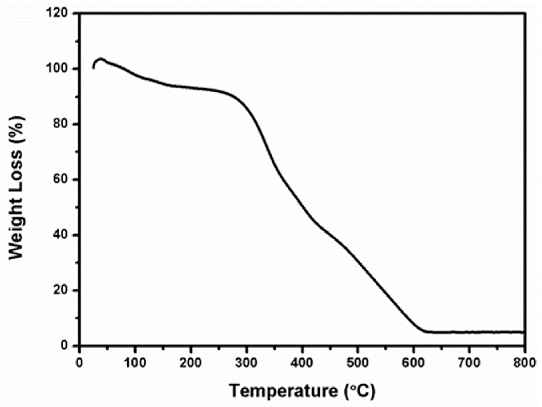
The TGA/DSC analysis of the Al2O3 electrospun fibers studied at a heating rate of 10 °C/min in air is shown in Figure 3. Two discrete regions of electrospun fibers weight loss occurred at about 135 °C and 300 °C. The weight loss at around 135 °C could be attributed to DMF solvent. Exothermic peaks at 300 °C with a large weight loss of ~80% corresponded to the decomposition of nitrate, PVP polymer, and other minor organic constituents during the burning combustion. For temperature higher than 600 °C, there was almost no change in the TGA curve, which confirmed that the complete decomposition of organic materials and polymer during the formation of Al2O3 fibers [40,41,42,43].

3.2. X-ray Diffraction Investigation

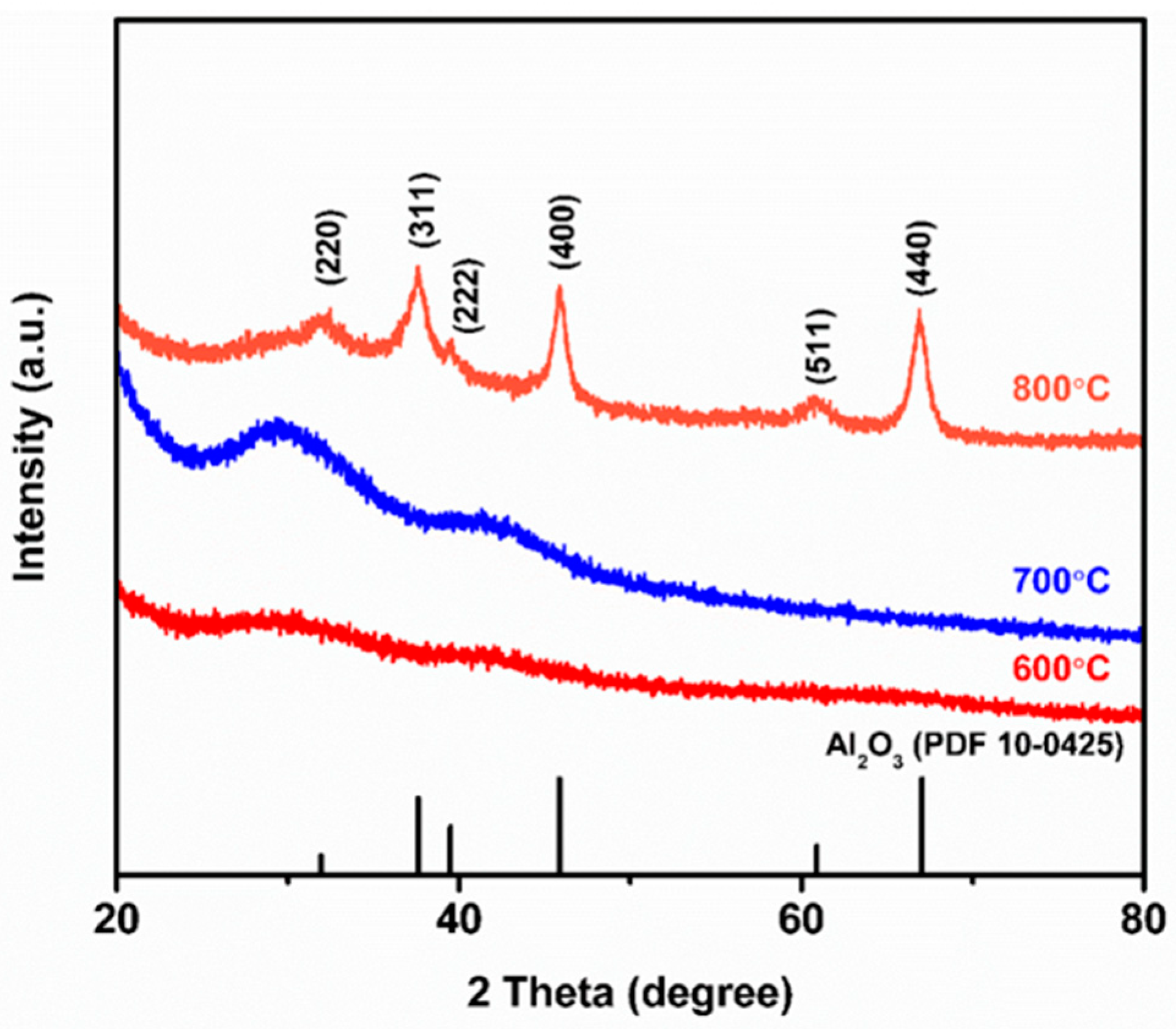
Figure 4 shows the XRD analysis of annealed Al2O3 fibers prepared by electrospinning method. The Al2O3 fibers were fabricated following the process mentioned in the last section with thermal annealing at elevated temperature for 2 h. We found no distinct diffraction peak for the as-spun fibers, but after the fibers were annealed at 600 °C, a clear amorphous phase was found. The XRD pattern indicated that the Al2O3 fibers became crystallized when the annealing temperature was over 800 °C [44].
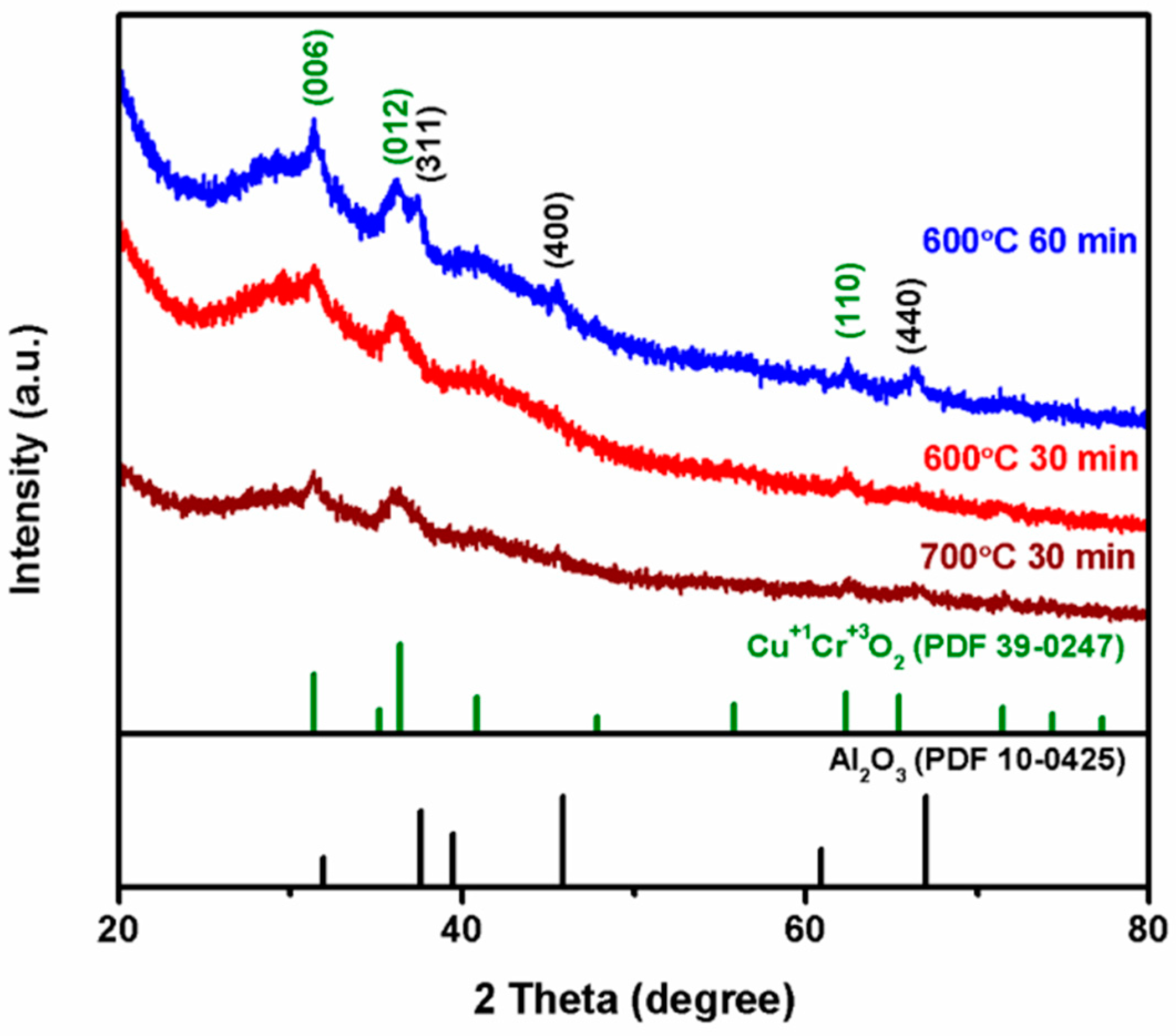
Figure 5 shows the XRD pattern of Al2O3 fibers with copper chromium ions deposited on the surfaces after annealing in vacuum at 600 °C for 30 min and 60 min, and at 700 °C for 30 min. The fibers were composed of an Al2O3 core and the copper chromium ion solution. The XRD studies show the peaks of Al2O3 for the fibers annealed at 600 °C for 60 min. It is presumed that the prolonged annealing time caused the crystallization of alumina [39,44].
Figure 6 shows the XRD pattern of Al2O3 fibers with copper chromium ion solution deposited on the surfaces after annealing at 600 °C for 30 min in vacuum followed by leaching with 2M H2SO4 solution due to the strong acid and without the formation of impurities. That solution was employed because Al2O3 is an amphoteric oxide and reacts with both acid and alkaline solutions. From comparing Figure 6 with Figure 5, it is clear that the main phase of CuCrO2 can be clearly seen in the XRD pattern after the acid immersion. For comparison, NaOH solution was also used to remove alumina cores. As can be seen from the figures, after immersion of the fibers in NaOH solution, only the CuO phase remain while the chromium oxide disappeared. Therefore, we concluded that Al2O3 fibers with copper chromium ion solution deposited on the surfaces could be treated with 2M H2SO4 solution and DI water to obtain CuCrO2 hollow nanotube [39].

3.3. SEM Analysis

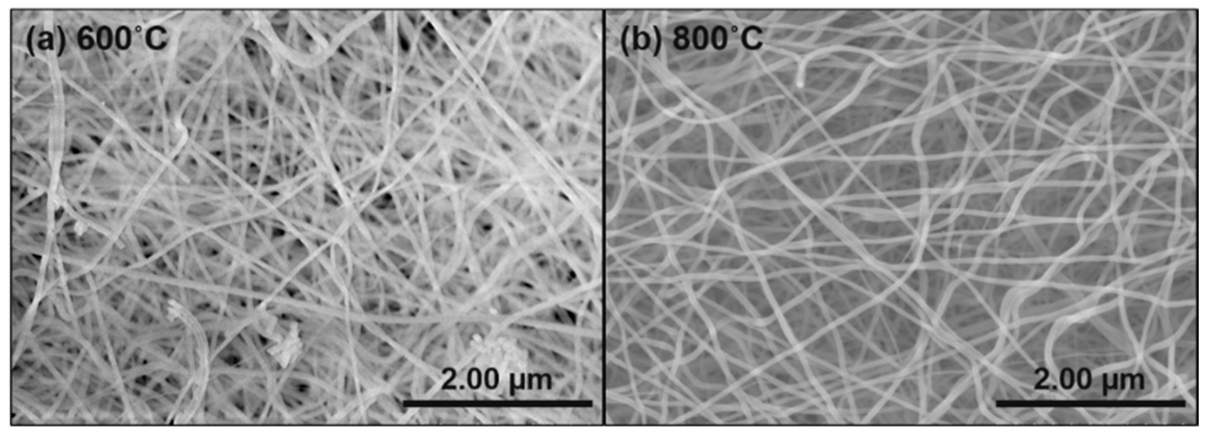
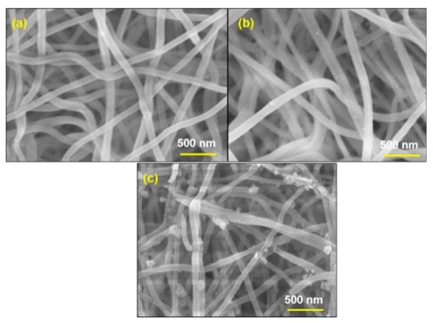
The SEM micrographs of as-spun Al2O3 precursor fibers have fine cylindrical with smooth surface morphology and shows in Scheme 1 [41]. Besides, the SEM image of Al2O3 electrospun fibers annealed for 2 h in air at 600 °C and 800 °C are presented in Figure 7. The morphology of the fibers reveals that the Al2O3 fibers have continuous, one-dimensional structure and that the diameter of each Al2O3 fiber is <100 nm. The morphology and dimension of Al2O3 fibers are essentially similar in the case of annealing temperature of 600 °C and the counterpart in 800 °C.
Figure 8 shows the morphology of Al2O3 fibers immersed in copper chromium ion solution and then dried for 2 min at 80 °C on a hotplate. After that, the Al2O3-CuCrO2 fibers were annealed in vacuum at 600 °C for 30 min (Figure 8a) and 60 min (Figure 8b), and at 700 °C for 30 min (Figure 8c). The surfaces of the fibers are smooth, and there is no specific change compared with calcined amorphous Al2O3 fibers. The copper chromium ion precursor solution, composed of mixed copper acetate, chromium acetate, and ethanolamine, was dissolved in ethylene glycol monomethyl ether.
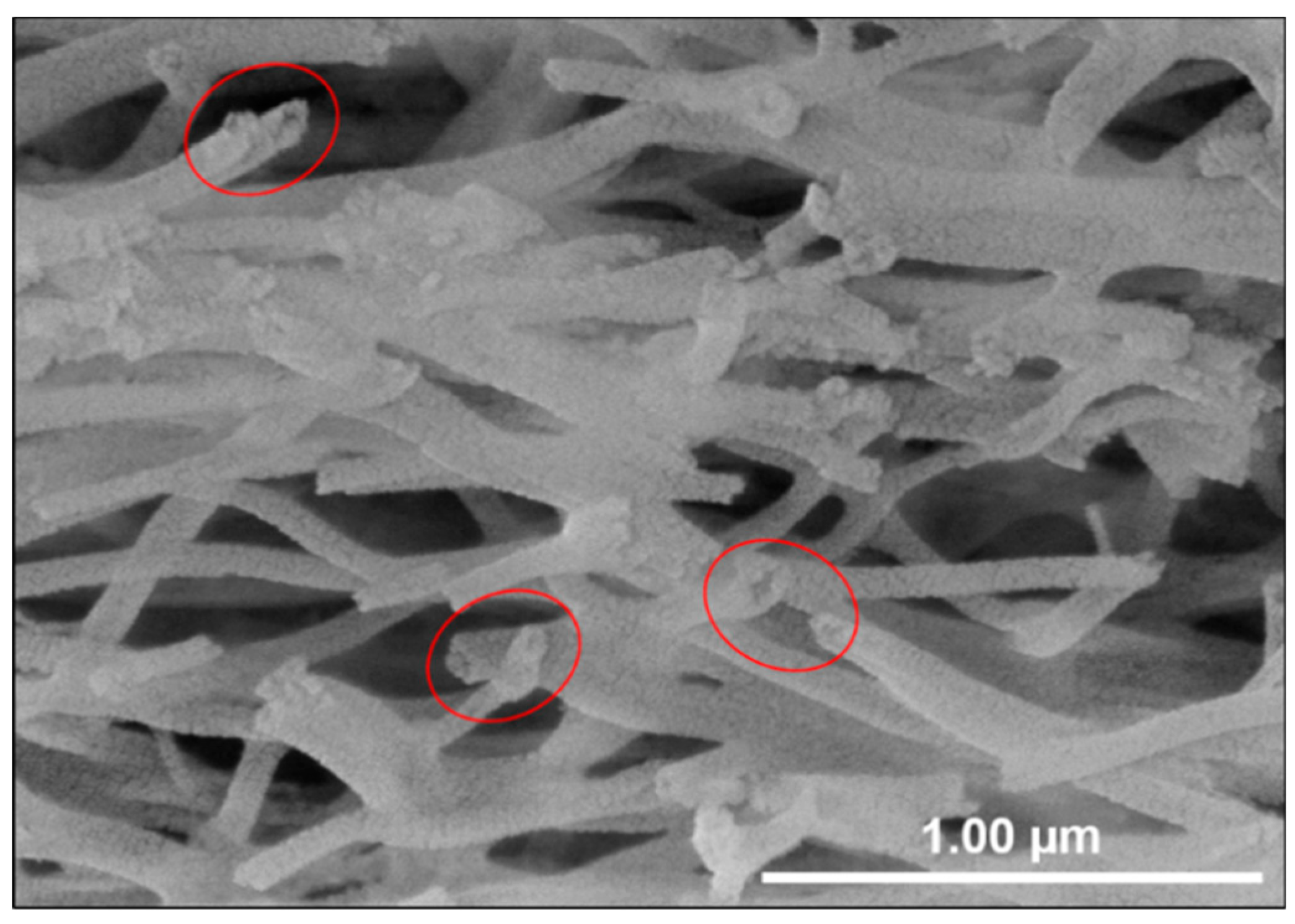
Figure 9 shows a SEM image of Al2O3-CuCrO2 nanofibers after immersion in 2M H2SO4 and oven-drying at 80 °C for 1 day. As can be seen from the SEM morphology, there is a hollow-like structure at the tip of the CuCrO2 nanotubes etched by 2M H2SO4. It was inferred that the Al2O3 core was mostly removed by the H2SO4 solution and remaining impurities were removed by DI water.

3.4. TEM Analysis

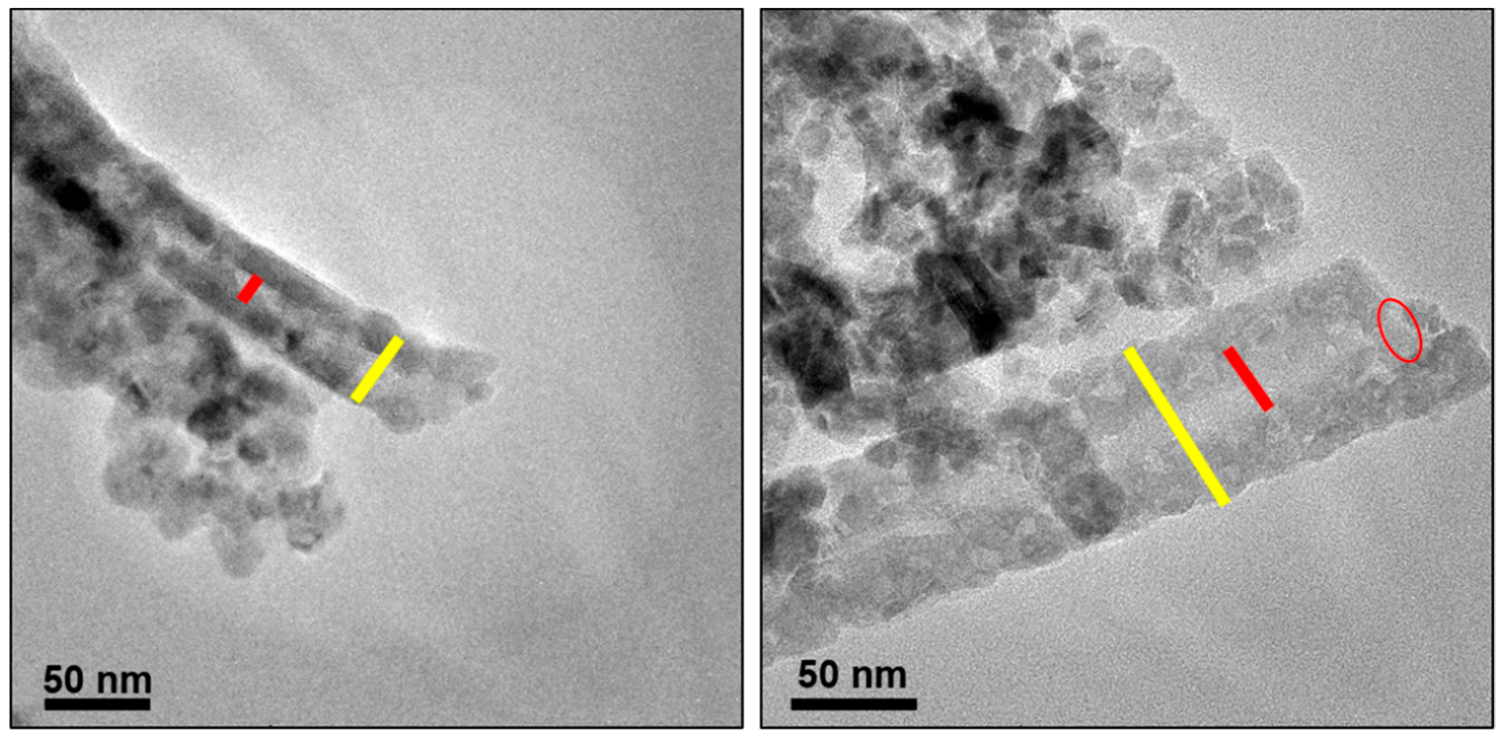
To identify the structure of the CuCrO2 hollow nanotubes synthesized by annealing and followed by chemical etching, TEM was used to further confirm the hollow structures of the nanotubes. The nanotubes were formed by using Al2O3 fiber as a template and depositing copper chromium ions on the tube surfaces so that the inner core was Al2O3. As shown in TEM image in Figure 10, the inner template of Al2O3 was completely etched away by 2M H2SO4 solution. The inner diameter of the nanotubes was about 70 nm, which is consistent with the diameter of Al2O3 fiber. The tube wall which consists of CuCrO2 features a thickness of several tens of nanometer [39]. These results indicate that the chemical etching method was successful in making CuCrO2 hollow nanotubes. Based on previous report, CuCrO2 hollow nanotubes have more porous cavity than none-hollow CuCrO2 nanofibers due to annealing condition [10].

3.5. STEM Analysis

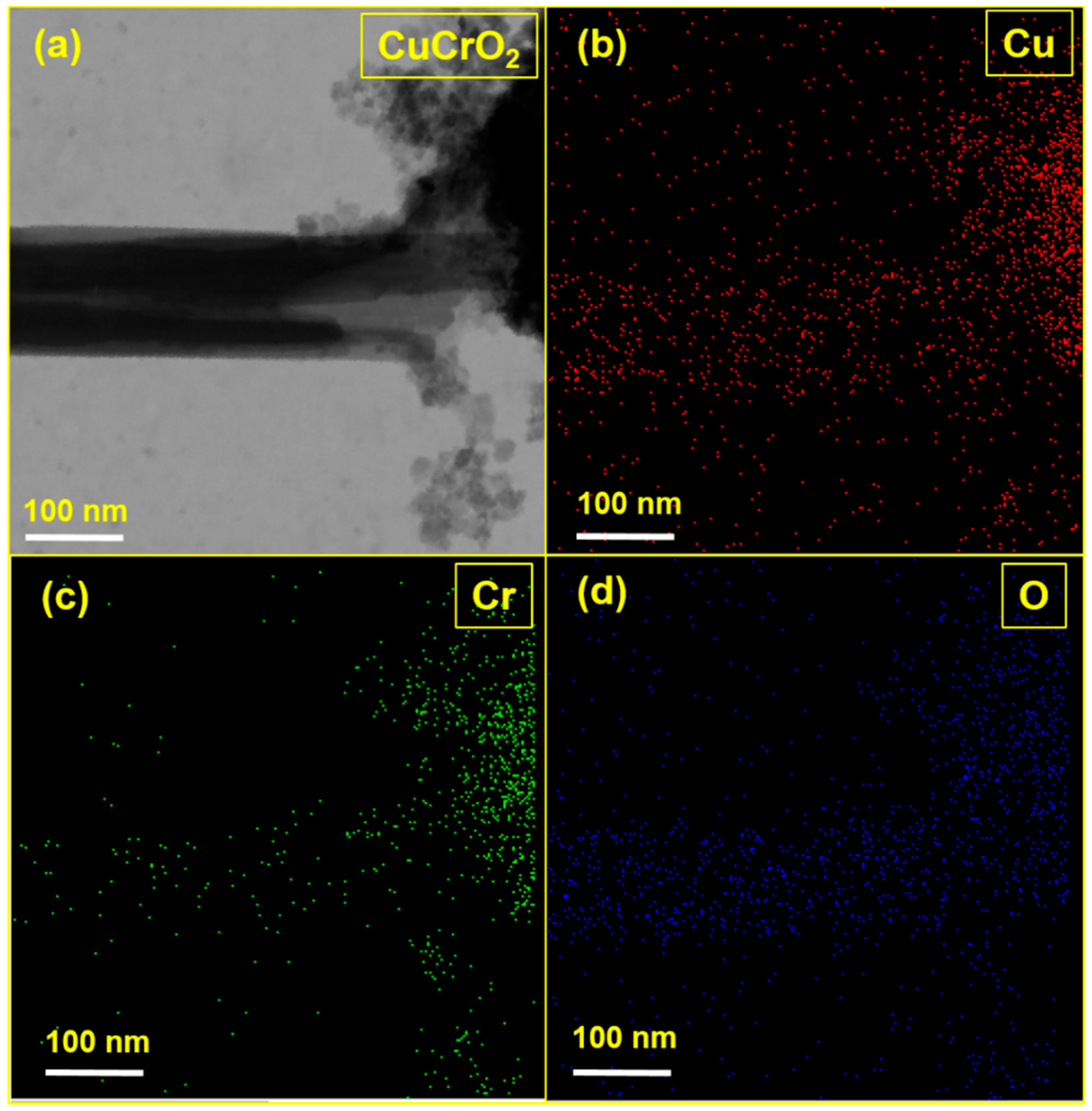
Figure 11a shows a STEM image of CuCrO2 hollow nanotube formed by annealing and chemical etching. The average diameter of the CuCrO2 hollow nanotube was about 100 nm and that of the center hollow was approximately 20 nm. These results exhibit that the chemical etching method succeeded in producing hollow nanotube. The STEM-EDS signals of CuCrO2 nanotube showed the presence of (Figure 11b) Cu, (Figure 11c) Cr, and (Figure 11d) O. Besides, the STEM-EDS spectrum showed higher numbers of atoms present in the tube edge than inside the cavity, which clearly shows the successful formation of the CuCrO2 hollow nanotubes.

4. Conclusions

CuCrO2 hollow nanotubes were successfully prepared by our proposed method using electrospun Al2O3 fiber as core template. The amorphous Al2O3 fibers were prepared by annealing the as-spun alumina precursor fibers at 600 °C for 2 h. These continuous and one-dimensional fibers were then deposited with CuCrO2 precursor and formed CuCrO2 cladding layer by thermal annealing at 600 °C for 30 min. After removing amorphous Al2O3 core fibers by using H2SO4, CuCrO2 nanotubes with an inner diameter of 70 nm and tube wall thickness of 30 nm were obtained. This work demonstrated a simple solution-based approach for the synthesis of oxide nanotubes and could be further extended to synthesize oxide materials with various complicated hollow structures.

Author Contributions

Conceptualization, H.-J.W. and T.-W.C.; data curation, H.-J.W. and T.-W.C.; formal analysis, H.-J.W.; funding acquisition, Y.-J.F., T.-W.C., and S.-S.L.; investigation, T.-W.C.; methodology, H.-J.W.; project administration, T.-W.C.; resources, T.-W.C.; supervision, T.-W.C.; validation, Y.-J.F., S.S., T.-W.C., and S.-S.L.; visualization, H.-J.W. and S.S.; writing—original draft, H.-J.W., S.-S.W., and T.-W.C.; writing—review and editing, H.-J.W., S.S., T.-W.C., S.-S.L., and J.-H.P.

Funding

This research was funded by University System of Taipei Joint Research Program (USTP-NTUT-TMU-108-06) and Ministry of Science and Technology, Taiwan grant number (MOST106-2221-E-027-041).

Acknowledgments

This work was supported by the Ministry of Science and Technology of Taiwan (MOST106-2221-E-027-041) and University System of Taipei Joint Research Program (USTP-NTUT-TMU-108-06). The authors appreciate the Precision Research and Analysis Center of National Taipei University of Technology (NTUT) for providing the measurement facilities.

Conflicts of Interest

The authors declare no conflict of interest.

References

  1. Huang, J.Y.; Zhong, L.; Wang, C.M.; Sullivan, J.P.; Xu, W.; Zhang, L.Q.; Mao, S.X.; Hudak, N.S.; Liu, X.H.; Subramanian, A.; et al. In situ observation of the electrochemical lithiation of a single SnO2 nanowire electrode. Science 2010, 330, 1515–1521. [Google Scholar] [CrossRef] [PubMed]
  2. Qian, H.; Lin, G.; Zhang, Y.; Gunawan, P.; Xu, R. A new approach to synthesize uniform metal oxide hollow nanospheres via controlled precipitation. Nanotechnology 2007, 18, 355602–355608. [Google Scholar] [CrossRef]
  3. Zhan, G.; Zeng, H.C. General strategy for preparation of carbon-nanotube-supported nanocatalysts with hollow cavities and mesoporous shells. Chem. Mater. 2015, 27, 726–734. [Google Scholar] [CrossRef]
  4. Choi, S.W.; Park, J.Y.; Kim, S.S. Growth behavior and sensing properties of nanograins in CuO nanofibers. Chem. Eng. J. 2011, 172, 550–556. [Google Scholar]
  5. Chiu, T.W.; Tu, C.H.; Chen, Y.T. Fabrication of electrospun CuCr2O4 fibers. Ceram. Int. 2015, 41, S399–S406. [Google Scholar] [CrossRef]
  6. Inagaki, M.; Yang, Y.; Kang, F. Carbon nanofibers prepared via electrospinning. Adv. Mater. 2012, 24, 2547–2566. [Google Scholar] [CrossRef] [PubMed]
  7. Acik, M.; Baristiran, C.; Sonmez, G. Highly surfaced polypyrrole nano-networks and nano-fibers. J. Mater. Sci. 2006, 41, 4678–4683. [Google Scholar] [CrossRef]
  8. Zhao, M.; Wang, X.; Ning, L.; He, H.; Jia, J.; Zhang, L.; Li, X. Synthesis and optical properties of Mg-doped ZnO nanofibers prepared by electrospinning. J. Alloys Compd. 2010, 507, 97–100. [Google Scholar] [CrossRef]
  9. Wang, J.; Daunis, T.B.; Cheng, L.; Zhang, B.; Kim, J.; Hsu, J.W.P. Combustion synthesis of p-type transparent conducting CuCrO2+x and Cu: CrOx thin films at 180 °C. ACS Appl. Mater. Interfaces 2018, 10, 3732–3738. [Google Scholar] [CrossRef]
  10. Shohl, W.A.D.; Daunis, T.B.; Wang, X.; Wang, J.; Zhang, B.; Barrera, D.; Yan, Y.; Hsu, J.W.P.; Mitzi, D.B. Room-temperature fabrication of a delafossite CuCrO2 hole transport layer for perovskite solar cells. J. Mater. Chem. A 2018, 6, 469–477. [Google Scholar] [CrossRef]
  11. Chiu, T.W.; Yang, Y.C.; Yeh, A.C.; Wang, Y.P.; Feng, Y.W. Antibacterial property of CuCrO2 thin films prepared by RF magnetron sputtering deposition. Vacuum 2013, 87, 174–177. [Google Scholar] [CrossRef]
  12. Tong, B.; Deng, Z.; Xu, B.; Meng, G.; Shao, J.; Liu, H.; Dai, T.; Shan, X.; Dong, W.; Wang, S.; et al. Oxygen vacancy defects boosted high performance p-Type delafossite CuCrO2 gas sensors. ACS Appl. Mater. Interfaces 2018, 10, 34727–34734. [Google Scholar] [CrossRef] [PubMed]
  13. Sathiskumar, P.S.; Thomas, C.R.; Madras, G. Solution combustion synthesis of nanosized copper chromite and its use as a burn rate modifier in solid propellants. Ind. Eng. Chem. Res. 2012, 51, 10108–10116. [Google Scholar] [CrossRef]
  14. Chiu, T.W.; Hong, R.T.; Yu, B.S.; Huang, Y.H.; Kameoka, S.; Tsai, A.P. Improving steam-reforming performance by nanopowdering CuCrO2. Int. J. Hydrogen Energy 2014, 39, 14222–14226. [Google Scholar] [CrossRef]
  15. Hwang, B.Y.; Sakthinathan, S.; Chiu, T.W.; Chuang, C.H.; Fu, Y.; Yu, B.S. Production of hydrogen from steam reforming of methanol carried out by self-combusted CuCr1-xFexO2 (x = 0–1) nanopowders catalyst. Int. J. Hydrogen Energy 2019, 44, 2848–2856. [Google Scholar] [CrossRef]
  16. Amrute, A.P.; Larrazabal, G.O.; Mondelli, C.; Ramirez, J.P. CuCrO2 delafossite: A stable copper catalyst for chlorine production. Angew. Chem. Int. Ed. 2013, 52, 9772–9775. [Google Scholar] [CrossRef]
  17. Fang, M.; He, H.; Lu, B.; Zhang, W.; Zhao, B.; Ye, Z.; Huang, J. Optical properties of p-type CuAlO2 thin film grown by rf magnetron sputtering. Appl. Surf. Sci. 2011, 257, 8330–8333. [Google Scholar] [CrossRef]
  18. Chen, H.; Wu, J. Transparent conductive CuFeO2 thin films prepared by sol gel processing. Appl. Surf. Sci. 2012, 258, 4844–4847. [Google Scholar] [CrossRef]
  19. Ueda, K.; Hase, T.; Yanagi, H.; Kawazoe, H.; Hosono, H.; Ohta, H.; Orita, M.; Hirano, M. Epitaxial growth of transparent p-type conducting CuGaO2 thin films on sapphire (001) substrates by pulsed laser deposition. J. Appl. Phys. 2001, 89, 1790–1793. [Google Scholar] [CrossRef]
  20. Lee, J.; Heo, Y.; Lee, J.; Kim, J. Growth of CuInO2 thin fi lm using highly dense Cu2O-In2O3 composite targets. Thin Solid Films 2009, 518, 1234–1237. [Google Scholar] [CrossRef]
  21. Liu, F.; Makino, T.; Hiraga, H.; Fukumura, T.; Kong, Y.; Kawasaki, M. Ultrafast dynamics of excitons in delafossite CuScO2 thin films. Appl. Phys. Lett. 2010, 96, 211904. [Google Scholar] [CrossRef]
  22. Lim, W.T.; Sadik, P.W.; Norton, D.P.; Pearton, S.J.; Ren, F. Dry etching of CuCrO2 thin films. Appl. Surf. Sci. 2008, 254, 2359–2363. [Google Scholar] [CrossRef]
  23. Chiu, T.W.; Shih, J.H.; Chang, C.H. Preparation and properties of CuCr1-xFexO2 thin films prepared by chemical solution deposition with two-step annealing. Thin Solid Films 2016, 618, 151–158. [Google Scholar] [CrossRef]
  24. Wang, Y.; Gu, Y.; Wang, T.; Shi, W. Structural, optical and electrical properties of Mg-doped CuCrO2 thin films by sol gel processing. J. Alloys Compd. 2011, 509, 5897–5902. [Google Scholar] [CrossRef]
  25. Nagarajan, R.; Draeseke, A.D.; Sleight, A.W.; Tate, J. p-type conductivity in CuCr1-xMgxO2 films and powders. J. Appl. Phys. 2001, 89, 8022–8025. [Google Scholar] [CrossRef]
  26. Kawazoe, H.; Yasukawa, M.; Hyodo, H.; Kurita, M.; Yanagi, H.; Hosono, H. P-type electrical conduction in transparent thin films of CuAlO2. Nature 1997, 389, 939–942. [Google Scholar] [CrossRef]
  27. Saadi, S.; Bouguelia, A.; Trari, M. Photocatalytic hydrogen evolution over CuCrO2. Sol. Energy 2006, 80, 272–280. [Google Scholar] [CrossRef]
  28. Zhang, J.; Qian, W.; Kong, C.; Wei, F. Increasing para-Xylene selectivity in making aromatics from methanol with a surface-modified Zn/P/ZSM-5 Catalyst. ACS Catal. 2015, 5, 2982–2988. [Google Scholar] [CrossRef]
  29. Rushi, A.D.; Datta, K.P.; Ghosh, P.S.; Mulchandani, A.; Shirsat, M.D. Selective discrimination among benzene, toluene, and xylene: Probing metalloporphyrin-functionalized single-walled carbon nanotube-based field effect transistors. J. Phys. Chem. C 2014, 118, 24034–24041. [Google Scholar] [CrossRef]
  30. Tunuguntla, R.H.; Henley, R.Y.; Yao, Y.C.; Pham, T.A.; Wanunu, M.; Noy, A. Enhanced water permeability and tunable ion selectivity in subnanometer carbon nanotube porins. Science 2017, 357, 792–796. [Google Scholar] [CrossRef] [Green Version]
  31. Zhang, Z.; Shi, H.; Wu, Q.; Bu, X.; Yang, Y.; Zhang, J.; Huang, Y. MOF-derived CeO2/Au@SiO2 hollow nanotubes and their catalytic activity toward 4-nitrophenol reduction. New J. Chem. 2019, 43, 4581–4589. [Google Scholar] [CrossRef]
  32. Cho, N.G.; Woo, H.S.; Lee, J.H.; Kim, I.D. Thin-walled NiO tubes functionalized with catalytic Pt for highly selective C2H5OH sensors using electrospun fibers as a sacrificial template. Chem. Commun. 2011, 47, 11300–11302. [Google Scholar] [CrossRef] [PubMed]
  33. Niu, X.; Zhao, T.; Yuan, F.; Zhu, Y. Preparation of hollow CuO@SiO2 spheres and its catalytic performances for the NO+CO and CO oxidation. Sci. Rep. 2015, 5, 9153. [Google Scholar] [CrossRef] [PubMed]
  34. Zhang, Y.; Williams, P.T. Carbon nanotubes and hydrogen production from the pyrolysis catalysis or catalytic-steam reforming of waste tyres. J. Anal. Appl. Pyrolysis 2016, 122, 490–501. [Google Scholar] [CrossRef] [Green Version]
  35. Li, P.; Shang, Z.; Cui, K.; Zhang, H.; Qiao, Z.; Zhu, C.; Zhao, N.; Xu, J. Coaxial electrospinning core-shell fibers for self-healing scratch on coatings. Chin. Chem. Lett. 2019, 30, 157–159. [Google Scholar] [CrossRef]
  36. Chiu, T.W.; Yu, B.S.; Wang, Y.R.; Chen, K.T.; Lin, Y.T. Synthesis of nanosized CuCrO2 porous powders via a self-combustion glycine nitrate process. J. Alloys Compd. 2011, 509, 2933–2935. [Google Scholar] [CrossRef]
  37. Cetin, C.; Akyildiz, H. Production and characterization of CuCrO2 nanofibers. Mater. Chem. Phys. 2016, 70, 138–144. [Google Scholar] [CrossRef]
  38. Tan, Y.; Jia, Z.; Sun, J.; Wang, Y.; Cui, Z.; Guo, X. Controllable synthesis of hollow copper oxide encapsulated into N-doped carbon nanosheets as high-stability anodes for lithium-ion batteries. J. Mater. Chem. A 2017, 5, 24139–24144. [Google Scholar] [CrossRef]
  39. Su, S.Y.; Wang, S.S.; Sakthinathan, S.; Chiu, T.W.; Park, J.H. Preparation of CuAl2O4 submicron tubes from electrospun Al2O3 fibers. Ceram. Int. 2019, 45, 1439–1442. [Google Scholar] [CrossRef]
  40. Chiu, T.W.; Chen, Y.T. Preparation of CuCrO2 nanowires by electrospinning. Ceram. Int. 2015, 41, S407–S413. [Google Scholar] [CrossRef]
  41. Mahapatra, A.; Mishra, B.G.; Hota, G. Synthesis of ultra-fine α-Al2O3 fibers via electrospinning method. Ceram. Int. 2011, 37, 2329–2333. [Google Scholar] [CrossRef]
  42. Kim, J.H.; Yoo, S.J.; Kwak, D.H.; Jung, H.J.; Kim, T.Y.; Park, K.H.; Lee, J.W. Characterization and application of electrospun alumina nanofibers. Nanoscale Res. Lett. 2014, 9, 44–49. [Google Scholar] [CrossRef] [PubMed]
  43. Kang, W.; Cheng, B.; Li, Q.; Zhuang, X.; Ren, Y. A new method for preparing alumina nanofibers by electrospinning technology. Text. Res. J. 2011, 81, 148–155. [Google Scholar] [CrossRef]
  44. Zhang, L.; Jiang, H.C.; Liu, C.; Dong, J.W.; Chow, P. Annealing of Al2O3 thin films prepared by atomic layer deposition. J. Phys. D Appl. Phys. 2007, 40, 3707–3713. [Google Scholar] [CrossRef]
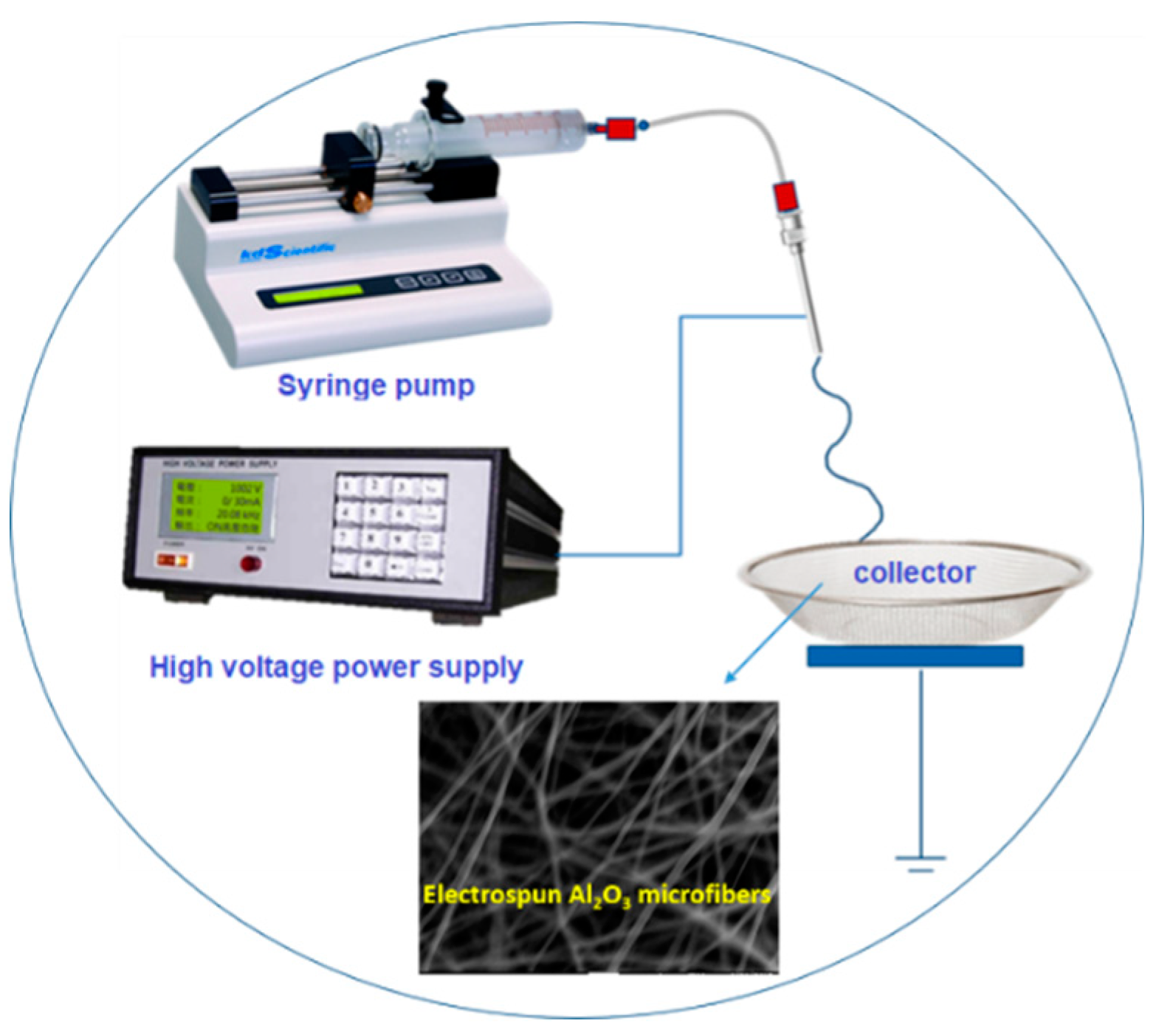
Figure 1. Schematic illustration of electrospinning preparation of as-spun fiber.
Nanomaterials 09 01252 g001
Figure 2. Schematic illustration of CuCrO2 hollow nanotubes fabrication process.
Nanomaterials 09 01252 g002
Figure 3. Thermogravimetric-derivative thermal analysis of as-spun Al2O3 precursor microfibers recorded in air at a heating rate of 10 °C/min.
Nanomaterials 09 01252 g003
Figure 4. XRD patterns of electrospun Al2O3 precursor fibers annealed for 2 h in the air at various temperatures (600 °C–800 °C).
Nanomaterials 09 01252 g004
Figure 5. XRD patterns of Al2O3 microfibers with copper chromium oxide deposited on the surfaces after annealing at 600 °C and 700 °C in vacuum.
Nanomaterials 09 01252 g005
Figure 6. XRD patterns of Al2O3 microfibers with copper chromium oxide deposited on the surfaces after annealing at 600 °C in vacuum followed by leaching with 2M H2SO4 and NaOH solution.
Nanomaterials 09 01252 g006
Figure 7. SEM images of electrospun Al2O3 microfibers annealed for 2 h at (a) 600 °C and (b) 800 °C.
Nanomaterials 09 01252 g007
Figure 8. SEM images of Al2O3-CuCrO2 nanofibers annealed at 600 °C for (a) 30 min, (b) 60 min, and at 700 °C for (c) 30 min.
Nanomaterials 09 01252 g008
Figure 9. SEM images of CuCrO2 hollow nanotubes after removal of Al2O3 core and impurities by 2M H2SO4 for 2 days and DI water.
Nanomaterials 09 01252 g009
Figure 10. TEM images of the CuCrO2 hollow nanotubes.
Nanomaterials 09 01252 g010
Figure 11. (a) STEM image of the CuCrO2 hollow nanotube, (b) Cu, (c) Cr, (d) O.
Nanomaterials 09 01252 g011