Robust Polymer Nanocomposite Membranes Incorporating Discrete TiO2 Nanotubes for Water Treatment
by
 , and
, and
Najia Mahdi
1, 
Pawan Kumar
1 ,
,
Ankur Goswami
1,2,
Basil Perdicakis
3,
Karthik Shankar
1,* and
Mohtada Sadrzadeh
4,*
1
Department of Electrical and Computer Engineering, University of Alberta, Edmonton, AB T6G1H9, Canada
2
Department of Materials Science and Engineering, Indian Institute of Technology Delhi, New Delhi 110016, India
3
Suncor Energy Inc., P.O. Box 2844, 150-6th Ave. SW, Calgary, AB T2P3E3, Canada
4
Department of Mechanical Engineering, University of Alberta, Edmonton, AB T6G1H9, Canada
*
Authors to whom correspondence should be addressed.
Nanomaterials 2019, 9(9), 1186; https://doi.org/10.3390/nano9091186
Submission received: 27 June 2019
/
Revised: 10 August 2019
/
Accepted: 13 August 2019
/
Published: 21 August 2019
(This article belongs to the Special Issue Wetting of Nanostructured Materials)
Abstract
:Polyethersulfone (PES) is a polymeric permeable material used in ultrafiltration (UF) membranes due to its high thermomechanical and chemical stability. The hydrophobic nature of PES membranes renders them prone to fouling and restricts the practical applications of PES in the fabrication of water treatment membranes. The present study demonstrates a non-solvent-induced phase separation (NIPS) approach to modifying PES membranes with different concentrations of discrete TiO2 nanotubes (TNTs). Zeta potential and contact angle measurements showed enhanced hydrophilicity and surface negative charge in TNTs/PES nanocomposite membranes compared to unmodified PES membranes. To discern the antifouling and permeation properties of the TNTs/PES membranes, steam assisted gravity drainage (SAGD) wastewater obtained from the Athabasca oil sands of Alberta was used. The TiO2 modified polymer nanocomposite membranes resulted in a higher organic matter rejection and water flux than the unmodified PES membrane. The addition of discrete TNTs at 1 wt% afforded maximum water flux (82 L/m2 h at 40 psi), organic matter rejection (53.9%), and antifouling properties (29% improvement in comparison to pristine PES membrane). An enhancement in fouling resistance of TNTs/PES nanocomposite membranes was observed in flux recovery ratio experiments.
1. Introduction
Water sources, such as lakes, groundwater, and rivers, have been contaminated by industrial waste disposal directly or indirectly [1]. The coastal areas of seas and oceans have also witnessed a dramatic increase in contaminants [2]. The shortage of clean water continues to increase due to which improved water usage efficiency is of paramount importance. Many industrial processes that use steam production in boilers are completely reliant on the supply of fresh water. Therefore, it is important to treat wastewater using energy efficient and robust techniques to ensure a continuous supply of fresh water. Various methods have been explored for water recycling that are both more energy efficient and environmentally sustainable [3]. Non-reactive interfacial interaction between a solid surface and aqueous medium, i.e., sorption and filtration based on microstructure, electrostatics, dispersion forces, etc., can be utilized for the cost-effective and facile purification of water [4]. Filtration using polymeric membranes for wastewater has seen increased adoption recently due to cost efficiency, low energy consumption, reliability, and ease of contaminant removal without using harmful products and no phase change at room temperature operations in comparison to other methods of water recycling [5,6,7,8,9].
Polymers are economical materials that can be used for large-scale membrane fabrication and are easy to modify as needed [9,10,11,12,13]. Polyethersulfone (PES) is a commonly used polymeric material for filtration applications due to its excellent thermomechanical, chemical, and contaminant separation properties. However, the hydrophobicity of PES results in poor performance of membrane which could hinder its anti-fouling properties negating many of its advantages during the filtration process [12]. Such poor anti-fouling properties have a detrimental effect on the permeation properties which causes a decrease in lifespan of the membrane resulting in an increase of operation cost [14]. Surface modified ultrafiltration (UF) membranes have been explored significantly to enhance the anti-fouling properties of the PES membrane by increasing the hydrophilicity and decreasing the surface charge as these parameters can have significant positive effects on the initial stages of fouling [15,16]. A variety of methods such as chemical grafting [17], the addition of antifouling blending materials [13], surface coating [18] and plasma treatment [19] have been explored to fabricate anti-fouling surfaces.
Currently, much research and development are underway on the surface modification of membranes by the incorporation of hydrophilic nanoparticles into the PES polymer to fabricate polymer nanocomposite membranes with higher surface hydrophilicity, increased anti-fouling properties and enhanced separation performance [20,21]. Numerous studies investigated the effect of various nanostructures including porous nanostructures such as carbon nanotubes (CNTs), cellulose nanocrystals, graphene oxide nanoplates, zeolites, mesoporous silica, and nonporous metal oxide nanoparticles, such as TiO2, MgO, ZnO, Al2O3, ZrO2, Fe2O3, and SiO2, on the structural morphology, transport properties, and surface characteristics of the fabricated nanocomposite membranes [22,23,24,25,26,27,28]. Atomic layer deposition (ALD) of metal oxides on the polymeric membrane is an approach that provides hydrophilicity and antifouling properties to the filtration membranes [29]. Yang et al. reported that ~10 nm TiO2 and SnO2-deposited via ALD on polyvinylidene fluoride (PVDF) membranes exhibit excellent anti-crude-oil fouling performance [30].
Recently, TiO2 nanostructures have received significant attention as membrane additives due to their stability, non-toxicity, self-cleaning ability, and natural abundance [31,32].
TiO2 nanotubes are hollow annular structures synthesized by the electrochemical anodization process that can be tailored to have cylindrical or square pores, with tunable diameters from ~10–1000 nm [33,34]. These nanotubes have a high effective surface area for interfacial adhesion to the polymer due to nanoscopic wall roughness, and the availability of both inner and outer tube walls. In the present study, the effect of incorporation of different concentrations of discrete TiO2 NTs on the physicochemical characteristics and permeation properties of the polyethersulfone (PES) membranes are reported. In addition, bare TiO2 nanotubes are superhydrophilic and can be rendered superhydrophobic or amphiphobic if needed by suitable surface functionalization [35,36].
The non-solvent-induced phase separation (NIPS) method was used to fabricate TiO2 NT incorporated PES membranes. The morphology of structures, chemical compositions and surface properties of the synthesized membranes were investigated by field emission scanning electron microscopy (FESEM), atomic force Microscopy (AFM), Fourier-transform infrared spectroscopy (FTIR), surface zeta potential, and water contact angle measurements. Water flux, organic matter rejection, and fouling resistance of the TiO2 NTs incorporated PES membranes were studied using both real and synthetically-produced water, and were compared with unmodified PES membranes.
2. Materials and Methods
2.1. Chemical and Reagents
The ultrafiltration membranes were made using the PES polymer with a molecular weight of 58 kDa obtained from BASF (Ludwigshafen, Germany). PVP (molecular weight, MW: 360 kDa) was procured from Sigma Aldrich (St. Louis, MO, USA) and used as an additive. Potassium chloride (KCl) and N,N-dimethylacetamide (DMA) were purchased from Fisher Scientific (Waltham, MA, USA). The discrete TiO2 NTs were synthesized using an electrochemical anodization process followed by sonication for discretization. Diethylene glycol (DEG) and ammonium fluoride (NH4F) were purchased from Sigma Aldrich to be used as an electrolyte in electrochemical anodization. Octadecylphosphonic acid (ODPA) to functionalize discrete nanotubes was also indented from Sigma Aldrich. An industrial wastewater, produced from steam-assisted gravity drainage (SAGD) in the Athabasca oil sands industry (AB, Canada) was used for the membrane permeation and fouling characteristics tests. The produced water is the feed water to the warm lime softener (WLS) of current SAGD water treatment facilities.
2.2. Preparation of TiO2 NTs/PES Membranes
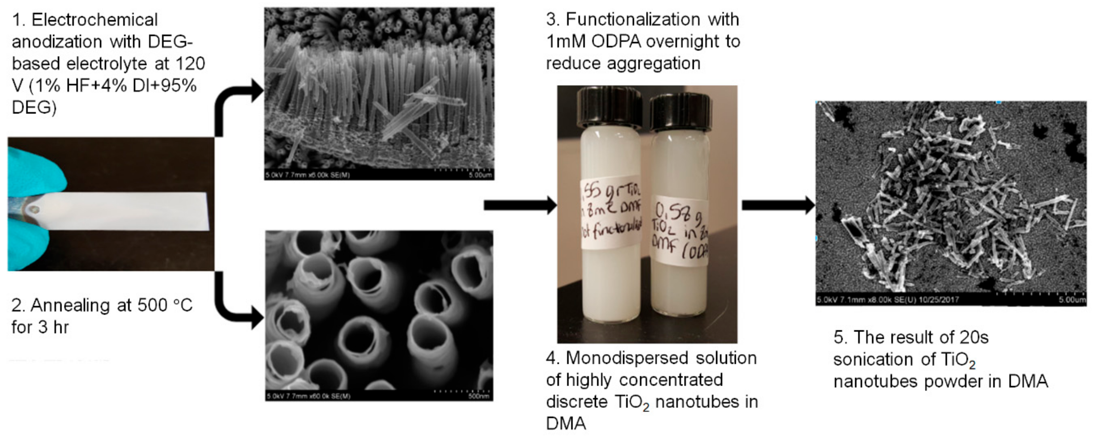
The preparation of TiO2 NTs/PES membranes consisted of two steps. The first step includes synthesis of TiO2 NTs via an electrochemical anodization process in DEG based electrolyte using a two-electrode electrochemical cell as shown in Figure 1. The synthesized TiO2 NTs on foil were annealed in a furnace at 500 °C for 3 h followed by functionalization with 1 mM ODPA solution overnight (Figure 2). The TiO2 NTs were discretized in 8 mL DMA using a probe sonicator. Different concentrations of discrete NT solutions were made to test the effect of concentration of nanomaterials on PES membrane structure and permeation properties.
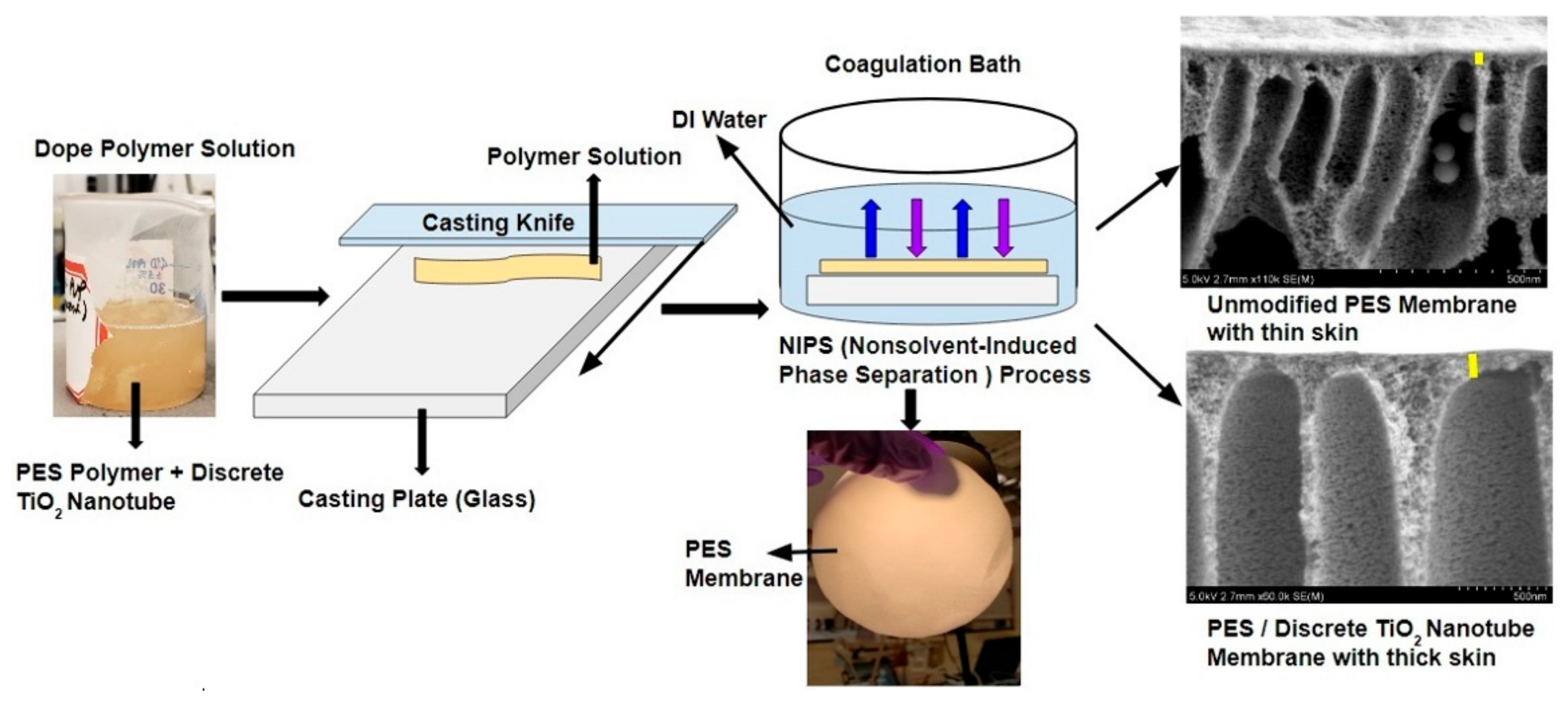
The second step, which is shown in Figure 3, was to fabricate TiO2 NTs/PES nanocomposite membranes. First, a casting solution was prepared by dissolving desired amounts of PES pellets, discrete TiO2 NTs and PVP in DMA solvent. In this work, to produce porous polymer films, homogeneously doped polymer solutions were prepared by mixing DMA with 14 wt% PES, 2 wt% PVP, and various ratios of discrete TiO2 NTs to polymer (1, 0.5, and 0.25 wt%). Next, a probe sonicator was used to disperse the discrete TiO2 NTs in DMA uniformly. PVP and PES mixture was then added to the discrete TiO2 NT/DMA solution and stirred overnight at 100 rpm. The obtained mixture, which is also called dope solution, was kept at room temperature for 24 h to remove air bubbles from the casting solution and to produce a defect-free membrane. A film applicator (Gardco, MICROM II, Pompano Beach, FL, USA) with a clearance gap of 190 μm and a casting speed of 5 mm/s was used to cast the solution on a flat glass surface. The film was then immersed in DI water and the membrane formation was completed after 24 h by liquid-liquid demixing.
2.3. Measurements of Porosity and Pore Size
The average pore size of the membrane was measured using the following expression below which was proposed by Guerout–Elford–Ferry [37]:
where Q is the permeate volumetric flow rate (m3/s), η is the water viscosity which is 8.9 × 10⁻⁴ Pas at 25 °C, and ΔP is the transmembrane pressure (Pa). The applied transmembrane pressures in this study were 10, 20, 30, and 40 psi.
Average porosity of membranes which is the ratio of total pore volume to the volume of the membrane was calculated using the gravimetric method [18]. The following equation was used to calculate the porosity of a membrane. To calculate the average porosity of each membrane the measurements were repeated three times.
where w1 and w2 are mass of wet and dry membranes (g) respectively, ρ is the water density (0.997 g/cm3 at 25 °C), l is the membrane thickness (cm), and A is the surface area (cm2) of the membrane.
2.4. Pure Water Flux Measurement
A dead-end filtration cell setup consisted of a membrane with an area of 41.8 cm2 and a dead-end stirred cell (Millipore Amicon Ultra, UFSC40001, Burlington, MA, USA) with a capacity of 400 mL. To monitor and record the permeate water flux over time, a digital balance (ME 4002, Mettler Toledo, Columbus, OH, USA) connected to a computer was employed. Various transmembrane pressures were applied using the pressurized nitrogen gas. The solution in the dead-end cell, in this case, the deionized (DI) water was stirred at a rate of 80 rpm. The equation below was used to calculate the water flux (J0):
where A is the membrane effective area (m2), W is the mass of the permeate water (kg), and t is the permeation time (h).
2.5. Fouling Tests
The fouling tests consisted of a three-step experimental procedure. The pure water flux, JW1, was first measured. The, JWF, water flux during the filtration of WLS inlet water, was then recorded. Lastly, the pure water filtration after hydraulic washing of the membrane surface with DI water for 15 min was performed and the pure water flux of the cleaned membrane JW2 was measured again. Based on these fouling tests, the fouling evaluation parameters namely total flux decline ratio (DRt), the sum of the reversible flux decline ratio (DRr), irreversible flux decline ratio (DRir), and flux recovery ratio (FRR) were calculated using the equations below [38]:
2.6. Total Organic Carbon Estimation
The total organic carbon (TOC) in the WLS inlet water was measured using a TOC analyzer (Shimadzu, Kyoto, Japan, model TOC-V; detection range 3–25,000 mg/L). The TOC analyzer measures the level of the organic contaminants or organic molecules in purified water and in this work the concentration of organic carbon atoms covalently bonded in the organic molecules of the PES based membranes was detected by the TOC analyzer. This parameter can be used to test the efficiency of the treatment process. The rejection of the organic matter can also be calculated using the measured TOC concentrations of the permeate (Cp) and feed (CF) solutions. The rejection was calculated using the equation below:
2.7. Chemical Composition Test (FTIR)
To verify the functionalization of titanium nanotube arrays (TNTAs) with ODPA, the IR active vibrations were recorded on a Digilab (Varian, Palo Alto, CA, USA) FTS 7000 FT-Infrared Spectrophotometer equipped with a UMA 600 Microscope and ZnSe ATR accessory. The sample was scratched from the surface and deposited directly on the ZnSe crystal and nitrogen gas flow was maintained through the ATR assembly. The spectra were accumulated by averaging 64 scans in the frequency range of 850–4000 cm−1.
2.8. X-ray Photoelectron Spectroscopy (XPS)
X-ray photoelectron spectroscopy (XPS) was used to determine the surface and subsurface (up to ~10 nm) chemical composition and oxidation state of materials using an Axis-Ultra, Kratos Analytical Limited instrument (Trafford Park, Manchester, UK) equipped with a monochromatic Al-Kα source (15 kV, 50 W) with photon energy of 1486.7 eV under ultrahigh vacuum (~10−8 Torr). The binding energy of adventitious carbons C1s peak at ≈ 284.8 eV was used as standard (carbon correction) to assign the peak of other elements. The raw spectra in vms format were deconvoluted into various peak components using CasaXPS software (version 2.3.22) and exported data was plotted in origin 2018.
2.9. Surface Properties (Wettability and Surface Charge)
Surface wetting characteristics of the fabricated membranes with various concentrations of discrete TiO2 NTs were measured using FTA-200 contact angle analyzer (First Ten Ångstroms, Portsmouth, VA, USA). DI water was used as a drop method to measure the contact angle. The lower the wettability of the membrane, the higher is the contact angle.
The Surpass3 zeta potential analyzer (Anton Paar GmbH, Graz, Austria) was used to analyze the charging behavior of the membrane surface when in contact with a liquid such as DI water. The surface zeta potential is derived from a flow of potential which arises from the interaction between the motions of liquid relating to the solid surface. The zeta potential values were obtained using various pH values (5, 6, 7, and 8) at 25 °C using 0.001 M KCl solution.
2.10. Membrane Morphology Study
The morphologies and cross-sections of the dried membranes were studied using the field emission scanning electron microscopy (Hitachi S-4800 Field Emission SEM, FE-SEM, Tokyo, Japan). The conductivity of the membranes was improved by sputtering 10 nm of gold on the surface of the membrane using Denton Gold Sputterer Unit (for SEM). A high vacuum with 5 kV/20 µA condition was used to image the cross-sectional structure of the prepared nanocomposite membranes.
2.11. Atomic Force Microscopy
Atomic force microscopy (AFM, Bruker, The Dimension Fast Scan Atomic Force Microscope, Santa Barbara, CA, USA) was used to image the surface topography of the TiO2 NTs/PES nanocomposite membrane.
3. Results
3.1. FTIR Measurement Results
A vibrational spectrum of ODPA monolayer functionalized TiO2 nanotubes was collected to validate the successful chemical functionalization of TiO2 NTs surface with ODPA molecules (Figure 4a). The FTIR spectrum of ODPA functionalized TiO2 exhibits a characteristic IR absorption band at 2848 and 2917 cm−1 due to symmetric and anti-symmetric C–H stretching vibrations of CH2 in alkyl chain of ODPA [35,36,39]. The IR peak at 3019 cm−1 was derived from C–H stretch of terminal methyl (–CH3) groups. Further, the peak observed at 3320 and 1605 cm−1 was assigned to O–H stretch and bending vibration of surface adsorbed water, respectively. Additionally, various peaks corresponding to symmetric and asymmetric bending vibration of CH2 and CH3 groups in ODPA were observed at 1492 cm−1 (CH2 + CH3 bend), 1450 cm−1 (CH2 in-plane bend) and 906 cm−1 (C–H out of plane bend) confirming the presence of ODPA molecule on the surface of TiO2 nanotubes. The IR spectrum of ODPA functionalized TNTAs in the frequency range 850–1300 cm−1 shows various IR bands at 1265, 1152, 1065 and 1027 cm−1 assigned to P=O vibration, PO3 asymmetric stretch, PO3 symmetric stretch and P–O–(H) symmetric stretch respectively. The presence of these IR bands clearly demonstrates successful chemical functionalization of TNTA with OPDA via the reaction between the –OH group on the surface of TiO2 and the phosphonate group (–H2PO4) on ODPA to form a phosphonate ester linkage (ROPO2–). TiO2 nanotubes were functionalized with the 18-carbon long ODPA to improve the monodispersity of the discrete TiO2 NTs in DMA (since the long alkyl chains prevent agglomeration of individual nanotubes). It is also well-known that organophosphonate monolayers bind very strongly to TiO2 surfaces and are not vulnerable to hydrolytic desorption [40].
3.2. XPS Results
The oxidation state and surface chemical attributes of ODPA functionalized TiO2 nanotubes were determined using X-ray photoelectron microscopy (XPS) (Figure 4b and Figure 5a–d). The appearance of C1s, O1s, Ti2p, P2p peaks in XPS elemental survey scan of ODPA functionalized TiO2 nanotubes demonstrate successful functionalization of TiO2 nanotubes with carbon and phosphorous rich organic molecules. The signal intensity of C1s peak was much higher, agreeing with a high concentration of carbon at the surface of TiO2 due to better coverage with ODPA monolayer (Figure 5b). High-resolution XPS spectra (HR-XPS) of ODPA functionalized TiO2 nanotubes in the Ti2p region show two peaks components located at a binding energy (BE) 458.8 and 464.6 eV, originated due to Ti2p3/2 and Ti2p1/2 peak components of the Ti4+ state in the TiO2 crystal lattice (Figure 5a) [41]. The peak separation of 5.8 eV between Ti2p3/2 and Ti2p1/2 peaks and their respective positions validate the O2− coordinated Ti4+ in tetragonal anatase phase TiO2 [42]. Core-level HR-XPS spectra of ODPA functionalized TiO2 nanotubes in O1s region can be deconvoluted into three peak components centered at BE ≈ 530.4, 531.5 and 532.7 eV (Figure 5b). The peak component at BE value 530.4 eV was originated from the contribution from Ti-coordinated oxygen atoms (O2−–Ti4+ forming TiO6 octahedron) present in the crystal lattice of TiO2 and P=O of surface-adsorbed ODPA molecule while an intense peak at BE ≈ 531.5 eV was corroborated to non-lattice adventitious oxygen atoms (–OH groups) and P–O oxygen of ODPA molecule (Figure 5b) [35,43]. Relatively small peak component at 532.7 eV was assigned to adventitious carbon bonded oxygen atoms (C=O). Deconvoluted HR-XPS spectra of ODPA functionalized TiO2 nanotubes in the C1s region gave two peak components, at 284.8 and 286.3 eV (Figure 5c). The major peak component at 284.8 eV originated from sp3 hybridized carbon atoms composing the alkyl chain of ODPA while the less intense shoulder peak at 286.3 eV was arose from the contribution of C–OH/C–P type carbon atoms [1,44]. Additionally, a single peak at BE ≈134.1 eV, in the HR-XPS of ODPA-grafted TiO2 nanotubes in the P2p region was assigned to phosphorous in the phosphonate group (P–O) bonded to TiO2 and confirms successful grafting of ODPA on TiO2’s surface (Figure 5d) [45].
3.3. Surface and Cross-Section Morphology
The membranes were immersed in liquid nitrogen for a few seconds to get a clear cut before preparing the samples for the internal cross-sectional imaging. The images of the unmodified PES membrane and the TiO2 NTs incorporated PES membranes are presented in Figure 6 for a comparison. The PES membranes used for microfiltration (MF) and UF purposes have a common trait which is a porous finger-type asymmetric structure consisting of macrovoids and a top dense skin layer [46]. Figure 6 shows this very clearly in all the membrane cross-sectional images. According to Figure 6, the addition of discrete TiO2 NTs to the unmodified PES membrane decreased the thickness of the membrane. However, the average skin thickness of the membranes increased as the concentration of discrete TiO2 NTs increased. A possible explanation is that the addition of the discrete NTs slows down the solvent/anti-solvent exchange rate in the coagulation bath and this causes the formation of thinner membranes with a thicker skin layer due to the entrapment of more discrete TiO2 NTs at the top surface during phase separation [38]. The discrete TiO2 NTs tend to enhance thermodynamic instability of the casting solution that accelerates the exchange of solvent and non-solvent [46]. The additional volume of TiO2 nanotubes, together with the existence of some portion of the hollow internal nanotube that is not infiltrated by the polymer, is expected to produce swelling of the polymer film by hydrophilic nanotubes before its solidification, thus allowing more non-solvent to flow into the casting film during NIPS process which, in turn, tends to increase the thickness of the membrane. However, an increase in the viscosity of the casting solution due to addition of discrete TiO2 NTs, together with the excellent miscibility of the PDPS-coated TiO2 NTs with PES, reversed these effects. As a result, the mutual diffusivities between non-solvent and solvent were reduced causing a decrease in the membrane thickness.
3.4. Atomic Force Microscopy (AFM)
Roughness is a direct metric of surface topography which can be measured with AFM. According to the images in Figure 7, the surface roughness increased with increasing the concentration of discrete TiO2 NTs in PES membranes. The surface roughness of pristine PES, 0.25% TiO2/PES, 0.5% TiO2/PES, and 1% TiO2/PES were measured to be 57.1, 83.3, 121, and 133 nm, respectively. The PES membrane with 1% discrete TiO2 NTs had the highest surface roughness. This membrane also had the lowest contact angle meaning that a part of improved wettability of nanocomposite membranes can be attributed to the increased roughness. According to the Wenzel equation, a membrane that is slightly hydrophilic becomes more hydrophilic as the surface roughness increases. In addition, based on Table 1, 1% TiO2/PES membrane was more negatively charged (−32.0 ± 0.6 mV) which proves the intended material improvement, e.g., addition of TiO2 NTs does increases the hydrophilicity of the membranes.
3.5. Contact Angle Measurement Results
Water contact angle analysis is a technique to study the hydrophilic properties of synthesized membranes. In general, a higher contact angle means that the membrane is more hydrophobic, and a lower contact angle reveals more hydrophilicity and higher surface energy of the membrane. A syringe which was positioned above the sample surface was used to deposit water droplets with a volume of 1 µL and a high-resolution camera was used to capture the side image of the droplet. The angle of the image was then analyzed using a protractor to measure the contact angles. For each membrane, three different measurements were taken from various spots on the membrane and the average values were reported. The contact angles of the membranes are presented in Table 1. The contact angle of the bare PES membrane was 65 ± 2° and as the concentration of discrete TiO2 NTs increased from 0.25% to 1%, the contact angle was observed to decrease from 49 ± 1° to 37 ± 1°. The contact angle of the bare TiO2 NTs was measured to be 8.0 ± 2°, which is highly hydrophilic compared to the PES membrane. The accumulation of hydrophilic discrete TiO2 NTs on the surface during phase inversion process reduced the interface energy. Based on contact angle measurements, the addition of discrete TiO2 NTs to PES membranes leads to the formation of more hydrophilic membranes. More hydrophilicity of microfiltration (MF)/ultrafiltration (UF) membranes can be correlated with their antifouling properties, as will be discussed later.
3.6. Membrane Surface Charge Results
The nature of surface charge on the membrane is a crucial parameter which governs the hydrophilicity and longevity of the membrane. The incorporation of discrete TiO2 NTs in TiO2 NTs/PES increases the hydrophilicity due to the raising the surface free energy which concomitantly reduces fouling of the PES membranes. The contact angle measurements and the surface charge of the membranes are presented in Table 1. The PES polymer consists of a polyetherphenylsulfone backbone with pendant sulfonate (–SO3H) groups and the number of sulfonic acid groups is dependent on the degree of sulfonation. At pH values higher than the isoelectric point (IEP), the sulfonate groups in PES polymer get dissociated into negatively charged sulfate ions. Due to low dissociation constant (pKa), the sulfonate groups readily get dissociated in water at pH-7, which gives them surface negative charge as observed from zeta potential measurements. In the pristine PES material, a certain fraction of sulfonate functionalities remains undissociated due to strong hydrogen bonding and inaccessibility of solvent. Upon the incorporation of discrete TiO2 NTs, the membrane surface becomes more accessible to solvents which facilitates dissociation of sulfonic acid groups and increases negative change. Additionally, the surface of TiO2 possesses plenty of hydroxyl groups (–OH) bonded with Ti atoms. These hydroxyl groups get deprotonated at elevated pH which further contributes to surface negative charge of the membrane. The PES membrane with 1 wt% TiO2 NTs is the most negatively charged in this study (see Table 1), and is expected to reduce the fouling by organic and inorganic contaminants in the water due to electrostatic repulsion [47].
3.7. Permeability of Membranes
In asymmetric membranes, there are two layers; the top dense layer which governs the permeation properties and the bottom porous layer which provides mechanical strength. The addition of the inorganic discrete TiO2 NTs which are polar attract the polar water molecules to the membrane surface which leads to an improvement in pure water flux. The pure water flux graph of pristine PES membrane and nanocomposite PES membranes with 0.25 to 1 wt% loading of discrete TiO2 NTs, as a function transmembrane pressure is shown in Figure 8a. The hydraulic permeability of the PES based membranes was obtained from the slopes of this figure. As can be seen in this figure, incorporating discrete TiO2 NTs has resulted in higher water permeability than unmodified PES membrane. The addition of more hydrophilic hydroxyl groups to the surface of the membrane improved the hydrophilicity (Table 1) which also increased water permeability of the membrane [48]. The nanocomposite membrane prepared by 1 wt% discrete TiO2 NTs was found to provide the maximum hydraulic permeability of 1.65 L/m2h(LMH)/psi. The extracted hydraulic permeability results from Figure 8a are shown in Figure 8b. As can be seen in this figure, increasing the concentration of discrete NTs up to 1 wt% increased the water permeability. This result can be attributed to a remarkable increase in hydrophilicity of membranes (Table 1). In addition, the overall thickness of membranes was reduced by the incorporation of TiO2 NTs (Figure 6), which decreased the resistance of the membranes against water transport.
3.8. Porosity and Mean Pore Radius of Membrane
The porosity (%) is the void space over the total volume of a polymer matrix and is one of the most important properties of a polymer. The pore size and pore volume are essential parameters to be measured prior to the application of a polymer in various fields. Porosity is measured by filling the pores either with a liquid or gas. Following the gravimetric method [49], the wet and dry masses of various membranes were measured, and this is shown in Table 2. The porosity of nanocomposite membranes is shown in Figure 9. By the addition of discrete TiO2 NTs up to 1 wt%, the overall porosity is increased. Theoretically, PVP as an additive to PES increases the thermodynamic instability due to its non-solvent property and kinetic hindrance due to its high molecular weight. As result, this relation between kinetic hindrance and thermodynamic enhancement of the casting solution affects the solidified membranes’ functional and structural properties by changing the porosity of phase inversion membranes [46,50]. The addition of hydrophilic discrete TiO2 NTs to the polymer solution further decreases its thermodynamic stability. Addition of both PVP and discrete TiO2 NTs results in thermodynamic variation which enhances the demixing of solution, thus leading to the formation of more porous structures. On the other hand, an increase in the viscosity of casting solution by the addition of TiO2 NTs can lead to the delayed demixing of solvent and non-solvent and thus formation of denser structures. This implies the presence of an optimum loading of discrete NTs (0.25 to 1 wt% TiO2 NTs) for improving the water flux. The increase in porosity is another parameter that improved the water flux results as shown in Figure 8. According to Figure 9, the mean pore size decreased, and the overall porosity increased as the percentage of discrete TiO2 NTs in membrane increased (see Equation (1)). The reduced pore diameter can potentially improve the separation properties of the nanocomposite membranes. As mentioned before, the separation properties of membranes are governed by the overall porosity and the membrane thickness and the addition of higher concentration of NTs increases both of these parameters, thus bettering the membrane properties for water treatment applications. In the present study, the main reason for the increase in the removal of organic matter by the addition of 1 wt% discrete TiO2 NTs, as will be explained in the next section, can be due to the increase in the thickness of skin layer (FESEM images in Figure 6).
3.9. Separation Performance of Membranes
The separation performance of nanocomposite membranes was evaluated by the filtration of WLS feed water. Table 3 presents the organic matter rejection results. A better performance for the removal of organic matter from oil sands produced water was observed for the nanocomposite membranes when compared with pristine membrane. The TOC rejection increased from 11.7% (unmodified PES membrane) to more than 50% for the 1 wt% discrete TiO2 NTs/PES nanocomposite membrane. Based on the data presented in Figure 4 and Table 3, the addition of 1 wt% discrete TiO2 NT has maximized both water flux (82 LMH at 40 psi) and TOC rejection (53.9%). The rejection was calculated using equation 8 in Section 2.5.
3.10. Fouling Characteristics of Membranes
The fouling characteristics of unmodified pristine PES membrane and discrete TiO2 NTs/PES nanocomposite membranes during the filtration of WLS feed water are shown in Table 3. To investigate the effect of TiO2 NTs on flux decline over time, all experiments were conducted at a similar initial permeation flux. Additionally, in all experiments, the feed solution chemistry, temperature, and hydrodynamic of membrane modules were kept similar. This allowed attributing the fouling propensity of membranes to the surface properties rather than feed properties and hydrodynamic conditions (e.g., drag force) [47,51]. The membranes were compressed at high pressure (70 psi) before the experiments to ensure that the flux decline over time is only due to the fouling of the membranes. At a constant initial flux, the flux decline can be attributed to the hydrophilicity, surface charge, and roughness of the modified membranes [52].
According to the Figure 10, the flux decline of the unmodified membrane is more than the PES membranes modified with discrete TiO2 NTs. The PES membrane with 1 wt% discrete TiO2 NTs showed approximately 29% more water flux than the unmodified PES membrane after 20 min of filtration. It is well known that the membranes with more negative surface charge and higher hydrophilicity have less interaction amongst the functional dissolved organic compounds in the feed solution and the polar groups on the membranes surface. This can be explained by formation of a water layer on the surface of the membrane that hinders foulant attachment to the membrane surface due to the formation of hydrogen bonds among the surface hydrophilic groups to start with. Due to the hydrophobic nature of most organic matter in the fluids tested [51], the fouling materials are less inclined to attach to a hydrophilic surface where there is smaller hydrophobic interaction with membrane surface. Membrane surface roughness, characterized by AFM, also plays a significant role in fouling. Foulant materials are entrapped in the edgy zones, behind the peaks and consequently clog the valleys on the surface of MF/UF membranes resulting in significant decrease in permeate flux. In this study, the combination of the hydrophilic surface of TiO2 NTs-based nanocomposite membranes along with their high surface potential (Table 1) seem to have dominated the roughness effect and made them less prone to fouling by dissolved organic matter, which can be beneficial for oil sands-produced water treatment.
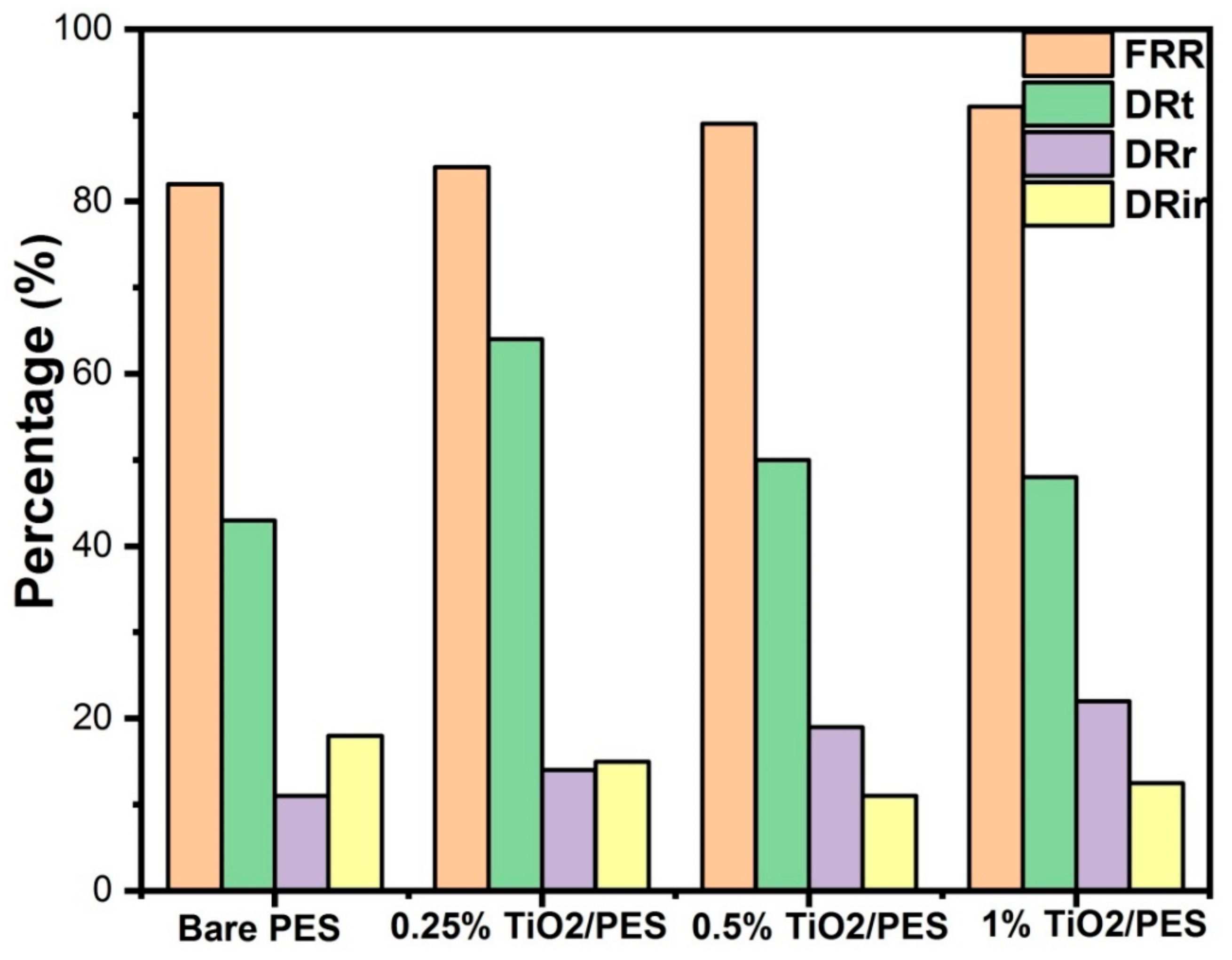
The total flux decline ratio (DRt), irreversible fouling ratio (DRir), water flux recovery ratio (FRR), and reversible fouling ratio (DRr) for the pristine PES membrane and TiO2 NTs/PES nanocomposite membranes are shown in Figure 11. The membranes showed flux decline during the filtration of WLS feed water for 20 min, which was possibly due to the existence of inorganic and organic materials on the surface of membranes. TiO2 NTs with high surface area are great adsorbent materials that adsorb foulants on the surface of the membrane thus decreasing the irreversible flux reduction. The DRir was found to be 12.5%, 11%, and 15% for 1, 0.5, and 0.25 wt% TiO2 loading as compared to 18% for unmodified PES membrane. The 1 wt% TiO2/PES membrane indicated a 9% greater flux recovery ratio than the pristine PES membrane, suggesting an improvement in antifouling characteristics of the unmodified membrane by the incorporation of TiO2 NTs.
4. Conclusions
In this study, discrete TiO2 NTs with various concentrations were blended into a polymeric membrane matrix via the NIPS technique. The surface properties of the nanocomposite membranes such as negative surface charge and hydrophilicity have noticeably changed to be stronger. The contact angle and zeta potential measurements showed the fabrication of more hydrophilic and negatively charged TiO2 NTs PES nanocomposite membranes. All discrete TiO2 NTs incorporated PES membranes showed better organic matter rejection and water flux when compared with the pristine PES membrane. The incorporation of discrete TiO2 NTs, up to 1 wt% enhanced the water flux due to an increase in overall porosity and hydrophilicity of the membranes. The most favorable loading to improve both organic matter rejection and water flux was found to be 1 wt% TiO2 NTs incorporated PES membranes which removed 53.9% of dissolved organic matter from SAGD-produced water. The SAGD WLS feed water was used to test the fouling propensity of membranes. The results showed that by the addition of discrete TiO2 NTs, the fouling tendency of the membranes has hindered due to improved surface properties. Discrete TiO2 NTs at its optimal loading (1 wt%) has provided the maximum rejection of organic matter (53.9%), water flux (82 LMH at 40 psi), and antifouling properties (29% improvement compared to pristine PES membrane). The flux recovery ratio (FRR) experiments have confirmed notable improvement in the antifouling property of discrete TiO2 NTs incorporated PES membranes.
As mentioned before, one of the potential benefits of TiO2 NTs incorporated PES membranes is their low cost compared to other nanomaterials due to their nearly endless lifetime. The low human toxicity, and high thermal and chemical stability are also other main advantages of TiO2 NTs which make them a good material in water filtration processes commercially. This membrane technology can easily be implemented into an existing commercial production facility due to facile synthesis methods of TiO2 NTs as well as the discrete TiO2 NTs. Since it is possible to produce discrete nanotubes in large scale, commercial fabrication of nanotube nanocomposite PES membranes will be an easy solution to fouling of membranes in water treatment.
Author Contributions
Conceptualization: B.P., K.S., and M.S.; methodology: N.M.; formal analysis: N.M. and P.K.; investigation: N.M., A.G., and P.K.; writing—original draft preparation: N.M.; writing—review and editing: P.K., K.S., and M.S.; visualization: P.K.; supervision: K.S. and M.S.; project administration: M.S.; funding acquisition: M.S.
Funding
This research was funded by Canada’s Oil Sands Innovation Alliance (COSIA) and the Natural Sciences and Engineering Research Council of Canada (NSERC).
Acknowledgments
N.M. thanks Behnam Khorshidi and Amin Karkooti for training her on the membrane characterization tools.
Conflicts of Interest
The authors declare no conflict of interest. Suncor Energy Inc. and its affiliates (collectively “Suncor”) do not make any express or implied representations or warranties as to the accuracy, timeliness, or completeness of the statements, information, data, and content contained in this paper and any materials or information (written or otherwise) provided in conjunction with this paper (collectively, the “Information”). The Information has been prepared solely for informational purposes only and should not be relied upon. Suncor is not responsible for and is hereby released from any liabilities whatsoever for any errors or omissions in the Information and/or arising out of a person’s use of, or reliance on, the Information. The funders had no role in the design of the study; in the collection, analyses, or interpretation of data; in the writing of the manuscript; or in the decision to publish the results.
References
- Li, J.; Liu, Z.; He, C.; Yue, H.; Gou, S. Water shortages raised a legitimate concern over the sustainable development of the drylands of northern China: Evidence from the water stress index. Sci. Total Environ. 2017, 590–591, 739–750. [Google Scholar] [CrossRef]
- Lim, D.-I.; Jung, S.W.; Choi, M.S.; Kang, S.M.; Jung, H.S.; Choi, J.Y. Historical record of metal accumulation and lead source in the southeastern coastal region of Korea. Mar. Pollut. Bull. 2013, 74, 441–445. [Google Scholar] [CrossRef] [PubMed]
- Hu, M.; Mi, B. Enabling Graphene Oxide Nanosheets as Water Separation Membranes. Environ. Sci. Technol. 2013, 47, 3715–3723. [Google Scholar] [CrossRef] [PubMed]
- Darling, S.B. Perspective: Interfacial materials at the interface of energy and water. J. Appl. Phys. 2018, 124, 030901. [Google Scholar] [CrossRef]
- Liu, J.; Tian, C.; Xiong, J.; Wang, L. Polypyrrole blending modification for PVDF conductive membrane preparing and fouling mitigation. J. Colloid Interface Sci. 2017, 494, 124–129. [Google Scholar] [CrossRef]
- Kang, G.-D.; Cao, Y.-M. Development of antifouling reverse osmosis membranes for water treatment: A review. Water Res. 2012, 46, 584–600. [Google Scholar] [CrossRef]
- Yin, J.; Deng, B. Polymer-matrix nanocomposite membranes for water treatment. J. Membr. Sci. 2015, 479, 256–275. [Google Scholar] [CrossRef]
- Genné, I.; Kuypers, S.; Leysen, R. Effect of the addition of ZrO2 to polysulfone based UF membranes. J. Membr. Sci. 1996, 113, 343–350. [Google Scholar] [CrossRef]
- Rezaee, R.; Nasseri, S.; Mahvi, A.H.; Nabizadeh, R.; Mousavi, S.A.; Rashidi, A.; Jafari, A.; Nazmara, S. Fabrication and characterization of a polysulfone-graphene oxide nanocomposite membrane for arsenate rejection from water. J. Environ. Health Sci. Eng. 2015, 13, 61. [Google Scholar] [CrossRef] [PubMed]
- Richards, H.L.; Baker, P.G.; Iwuoha, E. Metal nanoparticle modified polysulfone membranes for use in wastewater treatment: A critical review. J. Surf. Eng. Mater. Adv. Technol. 2012, 2, 183. [Google Scholar] [CrossRef]
- Ahmad, A.; Abdulkarim, A.; Ooi, B.; Ismail, S. Recent development in additives modifications of polyethersulfone membrane for flux enhancement. Chem. Eng. J. 2013, 223, 246–267. [Google Scholar] [CrossRef]
- Shen, J.-N.; Ruan, H.-M.; Wu, L.-G.; Gao, C.-J. Preparation and characterization of PES–SiO2 organic–inorganic composite ultrafiltration membrane for raw water pretreatment. Chem. Eng. J. 2011, 168, 1272–1278. [Google Scholar] [CrossRef]
- Zinadini, S.; Zinatizadeh, A.A.; Rahimi, M.; Vatanpour, V.; Zangeneh, H. Preparation of a novel antifouling mixed matrix PES membrane by embedding graphene oxide nanoplates. J. Membr. Sci. 2014, 453, 292–301. [Google Scholar] [CrossRef]
- Shi, X.; Tal, G.; Hankins, N.P.; Gitis, V. Fouling and cleaning of ultrafiltration membranes: A review. J. Water Process Eng. 2014, 1, 121–138. [Google Scholar] [CrossRef]
- Khulbe, K.; Feng, C.; Matsuura, T. The art of surface modification of synthetic polymeric membranes. J. Appl. Polym. Sci. 2010, 115, 855–895. [Google Scholar] [CrossRef]
- Rana, D.; Matsuura, T. Surface modifications for antifouling membranes. Chem. Rev. 2010, 110, 2448–2471. [Google Scholar] [CrossRef]
- Burtovyy, O.; Klep, V.; Turel, T.; Gowayed, Y.; Luzinov, I. Polymeric Membranes: Surface Modification by Grafting to Method and Fabrication of Multilayered Assemblies. In Nanoscience and Nanotechnology for Chemical and Biological Defense; ACS symposium series; American Chemical Society: Washington, DC, USA, 2009; pp. 289–305. [Google Scholar]
- Zarghami, S.; Mohammadi, T.; Sadrzadeh, M. Preparation, characterization and fouling analysis of in-air hydrophilic/underwater oleophobic bio-inspired polydopamine coated PES membranes for oily wastewater treatment. J. Membr. Sci. 2019, 582, 402–413. [Google Scholar] [CrossRef]
- Wavhal, D.S.; Fisher, E.R. Modification of polysulfone ultrafiltration membranes by CO2 plasma treatment. Desalination 2005, 172, 189–205. [Google Scholar] [CrossRef]
- Ng, L.Y.; Mohammad, A.W.; Leo, C.P.; Hilal, N. Polymeric membranes incorporated with metal/metal oxide nanoparticles: A comprehensive review. Desalination 2013, 308, 15–33. [Google Scholar] [CrossRef]
- Kim, J.; Van der Bruggen, B. The use of nanoparticles in polymeric and ceramic membrane structures: Review of manufacturing procedures and performance improvement for water treatment. Environ. Pollut. 2010, 158, 2335–2349. [Google Scholar] [CrossRef]
- Vatanpour, V.; Madaeni, S.S.; Moradian, R.; Zinadini, S.; Astinchap, B. Fabrication and characterization of novel antifouling nanofiltration membrane prepared from oxidized multiwalled carbon nanotube/polyethersulfone nanocomposite. J. Membr. Sci. 2011, 375, 284–294. [Google Scholar] [CrossRef]
- Zhang, D.; Karkooti, A.; Liu, L.; Sadrzadeh, M.; Thundat, T.; Liu, Y.; Narain, R. Fabrication of antifouling and antibacterial polyethersulfone (PES)/cellulose nanocrystals (CNC) nanocomposite membranes. J. Membr. Sci. 2018, 549, 350–356. [Google Scholar] [CrossRef]
- María Arsuaga, J.; Sotto, A.; del Rosario, G.; Martínez, A.; Molina, S.; Teli, S.B.; de Abajo, J. Influence of the type, size, and distribution of metal oxide particles on the properties of nanocomposite ultrafiltration membranes. J. Membr. Sci. 2013, 428, 131–141. [Google Scholar] [CrossRef]
- Li, Y.; Chung, T.-S.; Cao, C.; Kulprathipanja, S. The effects of polymer chain rigidification, zeolite pore size and pore blockage on polyethersulfone (PES)-zeolite A mixed matrix membranes. J. Membr. Sci. 2005, 260, 45–55. [Google Scholar] [CrossRef]
- Ganesh, B.; Isloor, A.M.; Ismail, A.F. Enhanced hydrophilicity and salt rejection study of graphene oxide-polysulfone mixed matrix membrane. Desalination 2013, 313, 199–207. [Google Scholar] [CrossRef]
- Huang, J.; Zhang, K.; Wang, K.; Xie, Z.; Ladewig, B.; Wang, H. Fabrication of polyethersulfone-mesoporous silica nanocomposite ultrafiltration membranes with antifouling properties. J. Membr. Sci. 2012, 423–424, 362–370. [Google Scholar] [CrossRef]
- Feng, Y.; Wang, K.; Davies, C.H.J.; Wang, H.T. Carbon Nanotube/Alumina/Polyethersulfone Hybrid Hollow Fiber Membranes with Enhanced Mechanical and Anti-Fouling Properties. Nanomaterials 2015, 5, 1366–1378. [Google Scholar] [CrossRef] [PubMed] [Green Version]
- Yang, H.-C.; Waldman, R.Z.; Chen, Z.; Darling, S.B. Atomic layer deposition for membrane interface engineering. Nanoscale 2018, 10, 20505–20513. [Google Scholar] [CrossRef]
- Yang, H.-C.; Xie, Y.; Chan, H.; Narayanan, B.; Chen, L.; Waldman, R.Z.; Sankaranarayanan, S.K.; Elam, J.W.; Darling, S.B. Crude-Oil-Repellent Membranes by Atomic Layer Deposition: Oxide Interface Engineering. ACS Nano 2018, 12, 8678–8685. [Google Scholar] [CrossRef]
- Li, J.-F.; Xu, Z.-L.; Yang, H.; Yu, L.-Y.; Liu, M. Effect of TiO2 nanoparticles on the surface morphology and performance of microporous PES membrane. Appl. Surf. Sci. 2009, 255, 4725–4732. [Google Scholar] [CrossRef]
- Homaeigohar, S.; Botcha, N.K.; Zarie, E.S.; Elbahri, M. Ups and Downs of Water Photodecolorization by Nanocomposite Polymer Nanofibers. Nanomaterials 2019, 9, 250. [Google Scholar] [CrossRef] [PubMed]
- Kar, P.; Zhang, Y.; Farsinezhad, S.; Mohammadpour, A.; Wiltshire, B.D.; Sharma, H.; Shankar, K. Rutile phase n- and p-type anodic titania nanotube arrays with square-shaped pore morphologies. Chem. Commun. 2015, 51, 7816–7819. [Google Scholar] [CrossRef] [PubMed] [Green Version]
- Mohammadpour, A.; Shankar, K. Anodic TiO2 nanotube arrays with optical wavelength-sized apertures. J. Mater. Chem. 2010, 20, 8474–8477. [Google Scholar] [CrossRef]
- Farsinezhad, S.; Waghmare, P.R.; Wiltshire, B.D.; Sharma, H.; Amiri, S.; Mitra, S.K.; Shankar, K. Amphiphobic surfaces from functionalized TiO2 nanotube arrays. RSC Adv. 2014, 4, 33587–33598. [Google Scholar] [CrossRef]
- Hua, W.; Kar, P.; Roy, P.; Bu, L.; Shoute, L.C.T.; Kumar, P.; Shankar, K. Resistance of Superhydrophobic Surface-Functionalized TiO2 Nanotubes to Corrosion and Intense Cavitation. Nanomaterials 2018, 8, 783. [Google Scholar] [CrossRef]
- Basri, H.; Ismail, A.F.; Aziz, M. Microstructure and anti-adhesion properties of PES/TAP/Ag hybrid ultrafiltration membrane. Desalination 2012, 287, 71–77. [Google Scholar] [CrossRef]
- Khorshidi, B.; Thundat, T.; Fleck, B.A.; Sadrzadeh, M. A novel approach toward fabrication of high performance thin film composite polyamide membranes. Sci. Rep. 2016, 6, 22069. [Google Scholar] [CrossRef]
- Kar, P.; Pandey, A.; Greer, J.J.; Shankar, K. Ultrahigh sensitivity assays for human cardiac troponin I using TiO2 nanotube arrays. Lab Chip 2012, 12, 821–828. [Google Scholar] [CrossRef]
- Cattani-Scholz, A. Functional Organophosphonate Interfaces for Nanotechnology: A Review. ACS Appl. Mater. Interfaces 2017, 9, 25643–25655. [Google Scholar] [CrossRef]
- Farsinezhad, S.; Sharma, H.; Shankar, K. Interfacial band alignment for photocatalytic charge separation in TiO2 nanotube arrays coated with CuPt nanoparticles. Phys. Chem. Chem. Phys. 2015, 17, 29723–29733. [Google Scholar] [CrossRef]
- Kar, P.; Zeng, S.; Zhang, Y.; Vahidzadeh, E.; Manuel, A.; Kisslinger, R.; Alam, K.M.; Thakur, U.K.; Mahdi, N.; Kumar, P.; et al. High rate CO2 photoreduction using flame annealed TiO2 nanotubes. Appl. Catal. B Environ. 2019, 243, 522–536. [Google Scholar] [CrossRef]
- Ai, G.; Mo, R.; Li, H.; Zhong, J. Cobalt phosphate modified TiO2 nanowire arrays as co-catalysts for solar water splitting. Nanoscale 2015, 7, 6722–6728. [Google Scholar] [CrossRef]
- Yang, D.-S.; Bhattacharjya, D.; Inamdar, S.; Park, J.; Yu, J.-S. Phosphorus-Doped Ordered Mesoporous Carbons with Different Lengths as Efficient Metal-Free Electrocatalysts for Oxygen Reduction Reaction in Alkaline Media. J. Am. Chem. Soc. 2012, 134, 16127–16130. [Google Scholar] [CrossRef]
- Ma, T.Y.; Qiao, S.Z. Acid–Base Bifunctional Periodic Mesoporous Metal Phosphonates for Synergistically and Heterogeneously Catalyzing CO2 Conversion. ACS Catal. 2014, 4, 3847–3855. [Google Scholar] [CrossRef]
- Sadrzadeh, M.; Bhattacharjee, S. Rational design of phase inversion membranes by tailoring thermodynamics and kinetics of casting solution using polymer additives. J. Membr. Sci. 2013, 441, 31–44. [Google Scholar] [CrossRef]
- Hayatbakhsh, M.; Sadrzadeh, M.; Pernitsky, D.; Bhattacharjee, S.; Hajinasiri, J. Treatment of an in situ oil sands produced water by polymeric membranes. Desalin. Water Treat. 2016, 57, 14869–14887. [Google Scholar] [CrossRef]
- Karkooti, A.; Yazdi, A.Z.; Chen, P.; McGregor, M.; Nazemifard, N.; Sadrzadeh, M. Development of advanced nanocomposite membranes using graphene nanoribbons and nanosheets for water treatment. J. Membr. Sci. 2018, 560, 97–107. [Google Scholar] [CrossRef]
- AlMarzooqi, F.A.; Bilad, M.R.; Mansoor, B.; Arafat, H.A. A comparative study of image analysis and porometry techniques for characterization of porous membranes. J. Mater. Sci. 2016, 51, 2017–2032. [Google Scholar] [CrossRef]
- Zhao, X.; Ma, J.; Wang, Z.; Wen, G.; Jiang, J.; Shi, F.; Sheng, L. Hyperbranched-polymer functionalized multi-walled carbon nanotubes for poly (vinylidene fluoride) membranes: From dispersion to blended fouling-control membrane. Desalination 2012, 303, 29–38. [Google Scholar] [CrossRef]
- Sadrzadeh, M.; Hajinasiri, J.; Bhattacharjee, S.; Pernitsky, D. Nanofiltration of oil sands boiler feed water: Effect of pH on water flux and organic and dissolved solid rejection. Sep. Purif. Technol. 2015, 141, 339–353. [Google Scholar] [CrossRef]
- Weis, A.; Bird, M.R.; Nyström, M.; Wright, C. The influence of morphology, hydrophobicity and charge upon the long-term performance of ultrafiltration membranes fouled with spent sulphite liquor. Desalination 2005, 175, 73–85. [Google Scholar] [CrossRef]
Figure 1.
Electrochemical anodization process used to form TiO2 NTs.
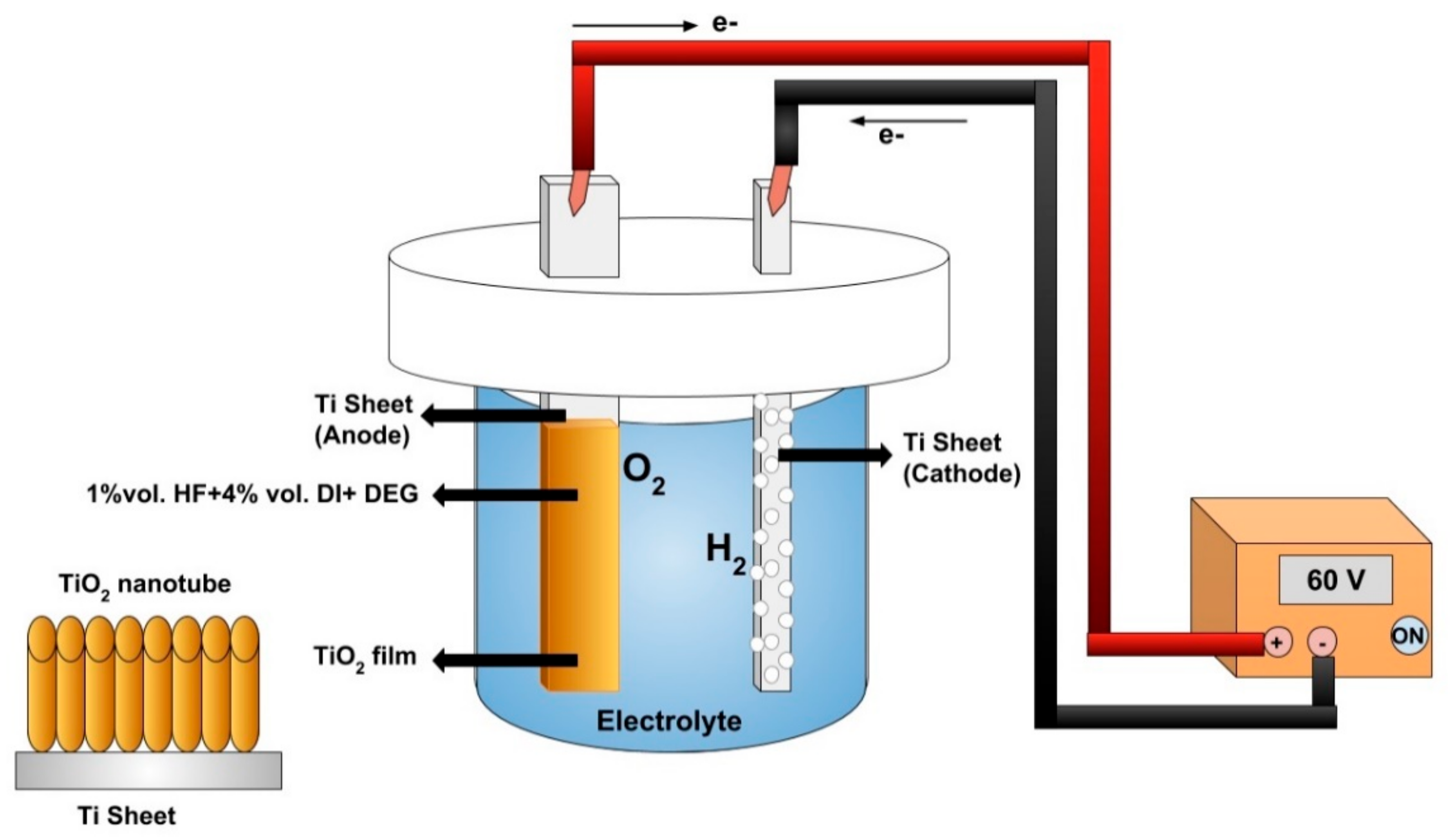
Figure 2.
Discrete TiO2 NT synthesis, functionalization, and discretization methods explained.

Figure 3.
Fabrication process of TiO2 NTs/PES nanocomposite membranes.

Figure 4.
(a) FTIR spectra of ODPA functionalized TiO2 NTs; (b) XPS elemental survey scan of ODPA functionalized TiO2 nanotubes.
Figure 4.
(a) FTIR spectra of ODPA functionalized TiO2 NTs; (b) XPS elemental survey scan of ODPA functionalized TiO2 nanotubes.
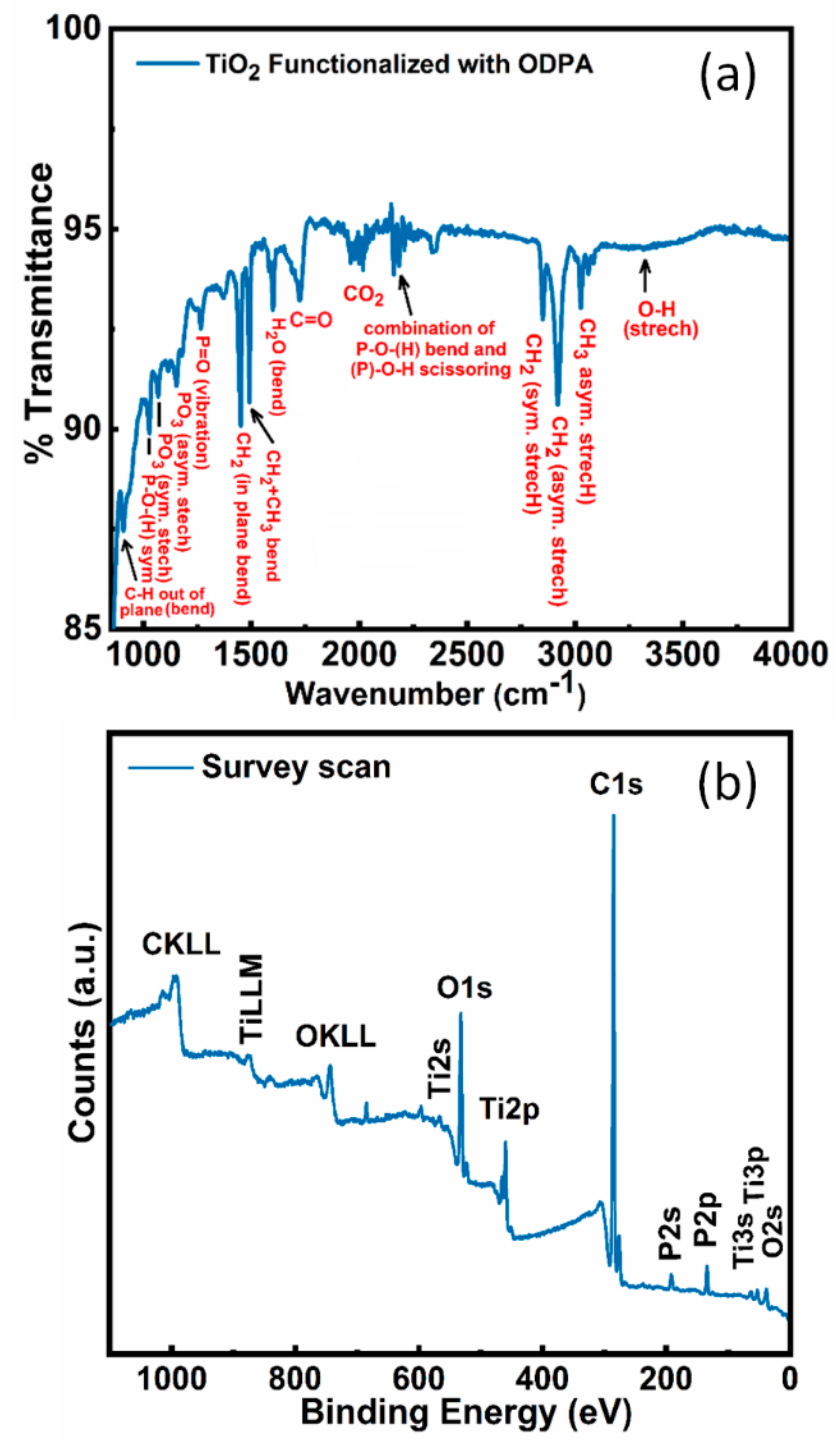
Figure 5.
Core-level HR-XPS spectra of ODPA functionalized TiO2 nanotubes in (a) Ti2p region; (b) O1s region; (c) C1s region; and (d) O1s region.
Figure 5.
Core-level HR-XPS spectra of ODPA functionalized TiO2 nanotubes in (a) Ti2p region; (b) O1s region; (c) C1s region; and (d) O1s region.
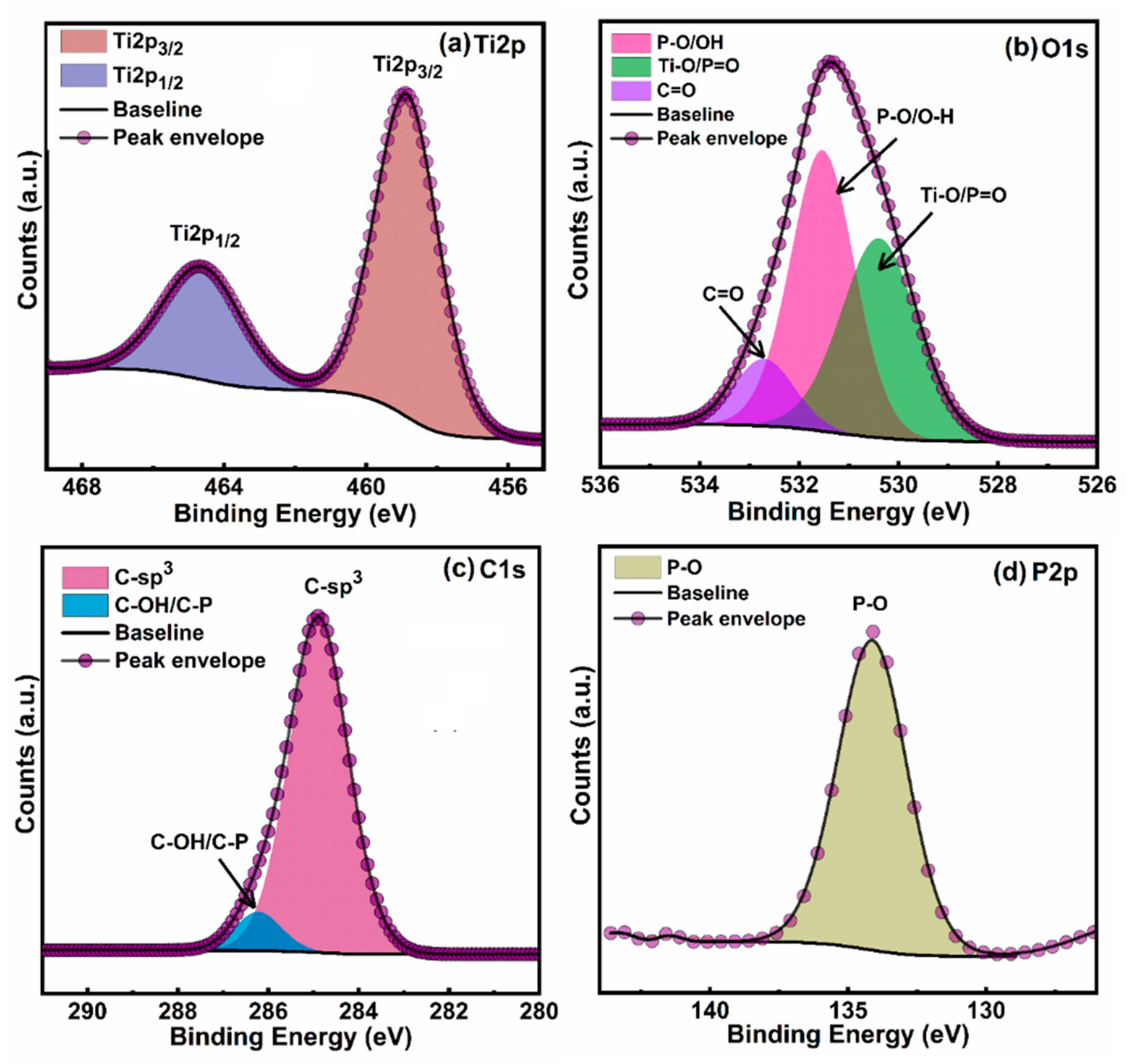
Figure 6.
The cross-sectional SEM images of pristine PES and TiO2 NTs/PES nanocomposite membranes (a–c); pristine PES membrane (d–f); 0.25% TiO2/PES membrane (g–i); 0.5% TiO2/PES membrane; and (j–l) 1% TiO2/PES membrane.
Figure 6.
The cross-sectional SEM images of pristine PES and TiO2 NTs/PES nanocomposite membranes (a–c); pristine PES membrane (d–f); 0.25% TiO2/PES membrane (g–i); 0.5% TiO2/PES membrane; and (j–l) 1% TiO2/PES membrane.
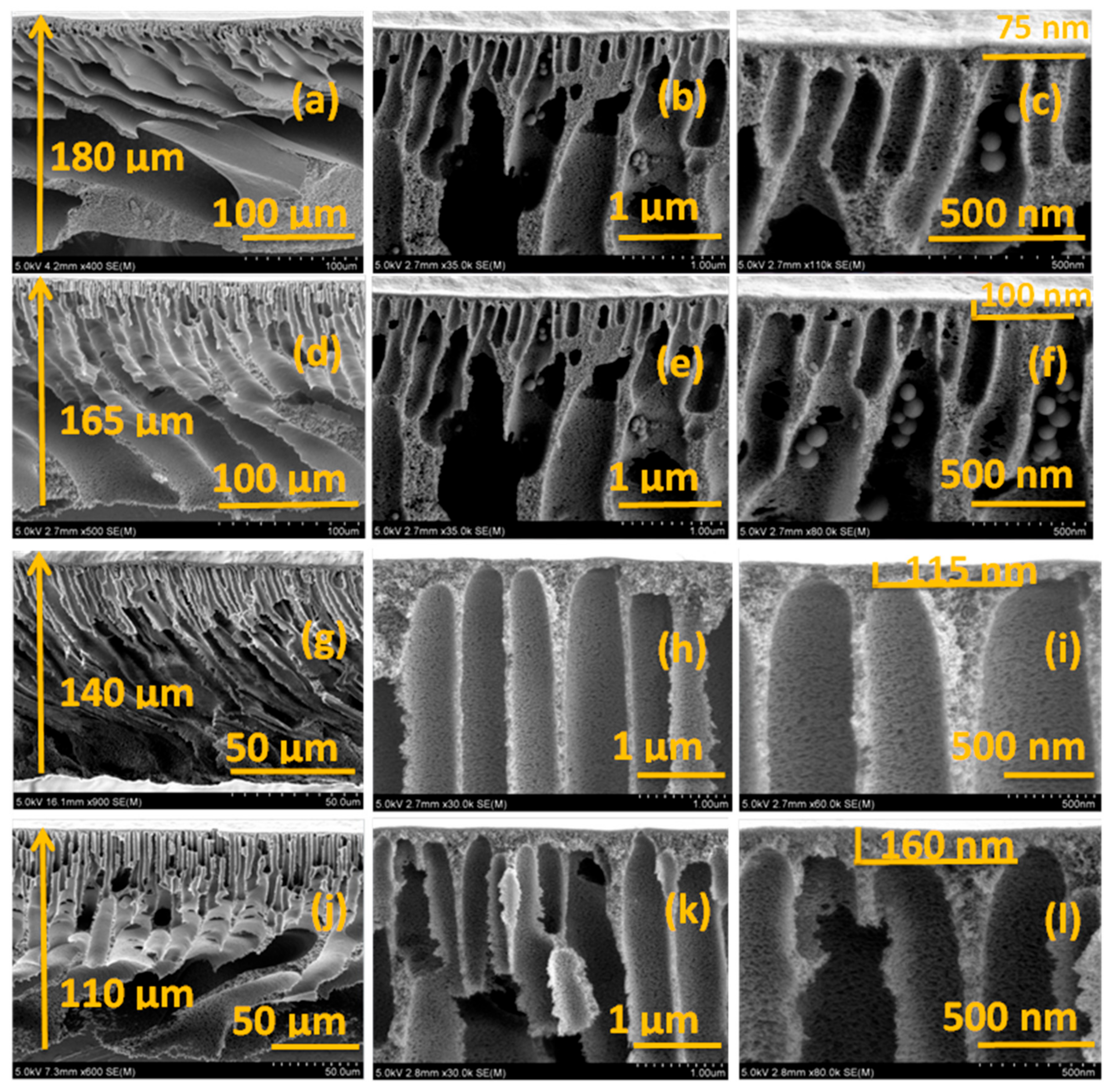
Figure 7.
Topography of discrete TiO2-based PES membranes using atomic force microscopy: (a) 1% TiO2/PES membrane; (b) 0.5% TiO2/PES membrane; (c) 0.25% TiO2/PES membrane; and (d) pristine PES membrane.
Figure 7.
Topography of discrete TiO2-based PES membranes using atomic force microscopy: (a) 1% TiO2/PES membrane; (b) 0.5% TiO2/PES membrane; (c) 0.25% TiO2/PES membrane; and (d) pristine PES membrane.

Figure 8.
(a) Permeation flux as a function of transmembrane pressure; and (b) hydraulic permeability of membranes as a function of NT concentration.
Figure 8.
(a) Permeation flux as a function of transmembrane pressure; and (b) hydraulic permeability of membranes as a function of NT concentration.
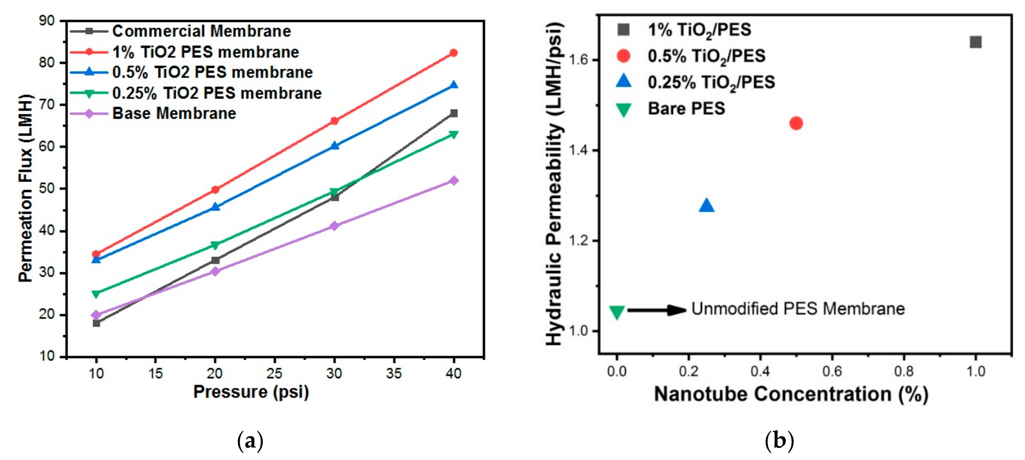
Figure 9.
(a) Porosity and (b) mean pore radius plots of various membranes.

Figure 10.
Water flux vs. time discrete TiO2 nanocomposite membranes and unmodified PES membrane due to fouling.
Figure 10.
Water flux vs. time discrete TiO2 nanocomposite membranes and unmodified PES membrane due to fouling.
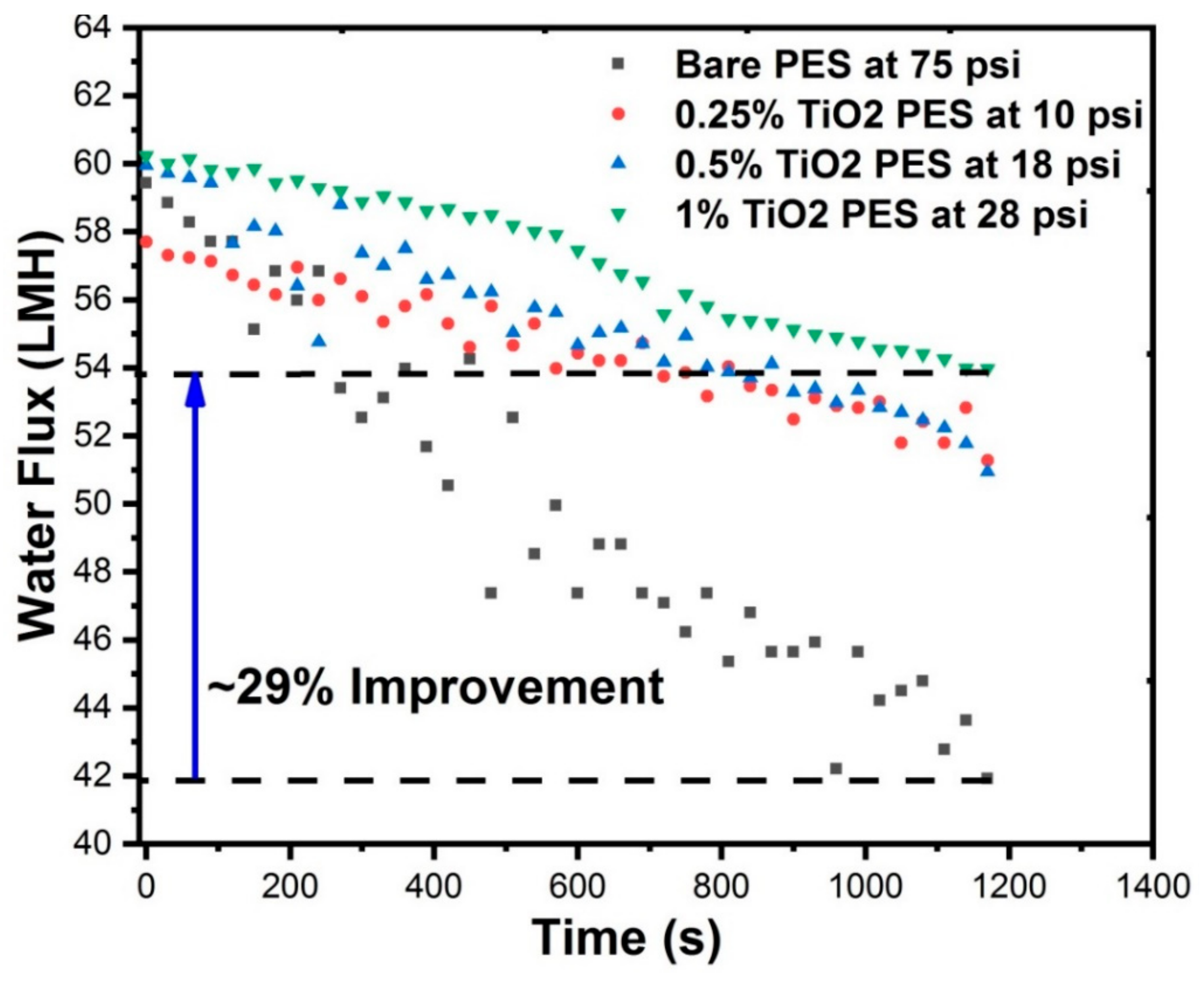
Figure 11.
Comparisons of fouling characteristics of unmodified PES and PES/discrete TiO2 nanocomposite membranes.
Figure 11.
Comparisons of fouling characteristics of unmodified PES and PES/discrete TiO2 nanocomposite membranes.


Table 1.
Surface charge/roughness of PES membranes and contact angle measurement results.
| Membranes | Surface Roughness (nm) | Contact Angle | Zeta Potential (mV) at pH 5 | Zeta Potential (mV) at pH 6 | Zeta Potential (mV) at pH 7 | Zeta Potential (mV) at pH 8 |
|---|---|---|---|---|---|---|
| Unmodified PES | 57.1 | 65.1 ± 2 ° | −24.2 ± 0.1 | −26.6 ± 0.7 | −27.5 ± 0.1 | −28.0 ± 0.9 |
| Unmodified TiO2 NT membrane | – | 8.0 ± 2 ° | −8.3 ± 0.5 | −8.8 ± 0.4 | −9.2 ± 0.2 | −10.1 ± 0.8 |
| PES with 0.25 wt% TiO2 NTs | 83.3 | 49.1 ± 1 ° | −25.2 ± 0.8 | −27.0 ± 0.6 | −27.8 ± 0.4 | −28.4 ± 0.5 |
| PES with 0.5 wt% TiO2 NTs | 121 | 40.5 ± 2 ° | −26.4 ± 0.7 | −27.3 ± 0.4 | −28.6 ± 0.6 | −29.7 ± 0.8 |
| PES with 1 wt% TiO2 NTs | 133 | 37.4 ± 1 ° | −28.2 ± 1 | −29.4 ± 0.4 | −31.5 ± 0.3 | −32.0 ± 0.6 |
Table 2.
Measured masses of dry and wet membranes for porosity and mean pore radius.
| Membrane | Mass of Dry Membrane (mg) | Mass of Wet Membrane (mg) |
|---|---|---|
| Unmodified PES | 14.6 ± 1 | 502.1 ± 2 |
| PES with 0.25 wt% TiO2 NTs | 25.0 ± 2 | 557.5 ± 3 |
| PES with 0.5 wt% TiO2 NTs | 27.2 ± 2 | 597.2 ± 1 |
| PES with 1 wt% TiO2 NTs | 24.2 ± 2 | 639.2 ± 2 |
Table 3.
Removal of organic matter from WLS inlet water (TOC: 500 ppm).
| Permeate TOC (mg/L) | Permeate TC (mg/L) | Permeate IC (mg/L) | WLS Feed Water Rejection (%) | |
|---|---|---|---|---|
| Bare PES | 441.28 | 468.74 | 27.46 | 11.7 |
| 1 wt% TiO2/PES | 230.70 | 253.80 | 23.10 | 53.9 |
| 0.5 wt% TiO2/PES | 413.51 | 447.40 | 33.90 | 17.3 |
| 0.25 wt% TiO2/PES | 424.23 | 451.20 | 26.97 | 15.15 |
© 2019 by the authors. Licensee MDPI, Basel, Switzerland. This article is an open access article distributed under the terms and conditions of the Creative Commons Attribution (CC BY) license (http://creativecommons.org/licenses/by/4.0/).
Share and Cite
MDPI and ACS Style
Mahdi, N.; Kumar, P.; Goswami, A.; Perdicakis, B.; Shankar, K.; Sadrzadeh, M. Robust Polymer Nanocomposite Membranes Incorporating Discrete TiO2 Nanotubes for Water Treatment. Nanomaterials 2019, 9, 1186. https://doi.org/10.3390/nano9091186
AMA Style
Mahdi N, Kumar P, Goswami A, Perdicakis B, Shankar K, Sadrzadeh M. Robust Polymer Nanocomposite Membranes Incorporating Discrete TiO2 Nanotubes for Water Treatment. Nanomaterials. 2019; 9(9):1186. https://doi.org/10.3390/nano9091186
Chicago/Turabian StyleMahdi, Najia, Pawan Kumar, Ankur Goswami, Basil Perdicakis, Karthik Shankar, and Mohtada Sadrzadeh. 2019. "Robust Polymer Nanocomposite Membranes Incorporating Discrete TiO2 Nanotubes for Water Treatment" Nanomaterials 9, no. 9: 1186. https://doi.org/10.3390/nano9091186
Note that from the first issue of 2016, this journal uses article numbers instead of page numbers. See further details here.