Article

Characterization of Sn4P3–Carbon Composite Films for Lithium-Ion Battery Anode Fabricated by Aerosol Deposition

1
Department of Electrical and Electronic Information Engineering, Toyohashi University of Technology, 1-1 Tempaku-cho, Toyohashi, Aichi 4418580, Japan
2
Department of Electrical and Electronic Engineering, Shizuoka Institute of Science and Technology, 2200-2 Toyosawa, Fukuroi, Shizuoka 437-8555, Japan
*
Author to whom correspondence should be addressed.
Nanomaterials 2019, 9(7), 1032; https://doi.org/10.3390/nano9071032
Submission received: 24 June 2019 / Revised: 4 July 2019 / Accepted: 16 July 2019 / Published: 19 July 2019

Abstract

:
We fabricated tin phosphide–carbon (Sn4P3/C) composite film by aerosol deposition (AD) and investigated its electrochemical performance for a lithium-ion battery anode. Sn4P3/C composite powders prepared by a ball milling was used as raw material and deposited onto a stainless steel substrate to form the composite film via impact consolidation. The Sn4P3/C composite film fabricated by AD showed much better electrochemical performance than the Sn4P3 film without complexing carbon. Although both films showed initial discharge (Li+ extraction) capacities of approximately 1000 mAh g−1, Sn4P3/C films retained higher reversible capacity above 700 mAh g−1 after 100 cycles of charge and discharge processes while the capacity of Sn4P3 film rapidly degraded with cycling. In addition, by controlling the potential window in galvanostatic testing, Sn4P3/C composite film retained the reversible capacity of 380 mAh g−1 even after 400 cycles. The complexed carbon works not only as a buffer to suppress the collapse of electrodes by large volume change of Sn4P3 in charge and discharge reactions but also as an electronic conduction path among the atomized active material particles in the film.

1. Introduction

Li-ion batteries (LiBs) are widely used as a power source for portable electronic devices, and recently have attracted much attention as a large-scale power source for electric vehicles and plugin hybrid electric vehicles. In order to achieve advanced LiBs with higher energy density, development of anode materials with higher capacity is indispensable. Graphite with a theoretical capacity of 372 mAh g−1 is commonly used as an anode for LiBs, while lithium alloys such as Li–Si and Li–Sn with a higher theoretical capacity (Li4.4Si: 4200 mAh g−1, Li4.4Sn: 990 mAh g−1) have been extensively studied [1,2,3]. However, they result in poor cycling stability due to a large volume change during charge and discharge reactions. In order to improve the cycling stability, various composite materials including metal oxides, multiphase alloys and intermetallic compounds have been studied as alternatives to graphite anode for LiBs [3,4,5,6,7]. These materials show much higher capacities than graphite and improved cycling performance compared to lithium alloy materials. The enhancement of cycling stability in these Li-alloy-based materials attributed to an inactive matrix [4]. Li-alloy-based materials form an inactive matrix during cycling and this matrix is expected to suppress the volume change of the alloying reaction, and keeps the electrode particles mechanically connected together resulting in a reversible alloying reaction.
Tin phosphide Sn4P3 (theoretical gravimetric capacity = 1255 mAh g−1) is known as one of the high capacity alloy-based anode materials for LiBs [8,9,10,11]. Sn4P3 has a layered structure (space group: R-3m) suitable for lithium insertion and high intrinsic electronic conductivity at room temperature. In addition, Sn4P3 forms Sn and Li3P in the lithium insertion reaction. Li3P has high ionic conductivity [12] and would act as a matrix for suppressing the volume change during the alloying reaction. According to these features, application of a Sn4P3 anode for high-capacity sulfide-based solid-state batteries has been also demonstrated [13].
As reported in the literature [8,9], Sn4P3 shows initial reversible capacity as high as 900 mAh g−1 and by controlling the electrical potential window in galvanostatic charge and discharge testing, it maintains a reversible capacity above 400 mAh g−1 after 50 cycles. Reducing the size and morphology of Sn4P3 particles [14,15] and doping of a small amount of Fe [16] and Mn [17] into Sn4P3 are also effective for further improvement of the cycling stability. Moreover, complexing the carbon materials with nano-structured Sn4P3 particles significantly enhances both the rate performance and cycling stability [18,19,20,21,22,23,24,25]. The complexed carbon behaves as the buffer for the volume change of active material particles during charge and discharge reaction and maintains the electric conduction between the particles.
In general, the electrodes used in actual batteries are fabricated by coating a slurry composed of electrode active materials on metallic foils and contain conducting carbon additives and binders. For the case of carbon complexed alloy-based anodes, the weight fraction of active materials in an electrode becomes small (less than ~70%) due to significant amounts of conducting additives and binders. Consequently, gravimetric specific capacity calculated by the total mass of the electrode (including carbon additives and binders) is reduced significantly. To address this issue, we are focusing on the aerosol deposition (AD) method [26,27,28] as an electrode fabrication process, which uses impact consolidation for ceramic particles at room temperature. This method is known as a fabrication process of various functional ceramic films at room temperature. By controlling the size and morphology of the base powder material, the film fabricated by AD has a dense structure made of nanocrystalline particles, and the structural and physical properties are similar to the base powder material. Moreover, adhesion strength between the film formed by AD and the substrate is high without adding binders [26,27]. To date, several works for the application of AD to rechargeable battery materials have been reported. The electrochemical performance for film-shaped electrodes of Si alloy or composite [29,30], tin-phosphide with different compositions [31], transition metal oxides [32,33,34,35,36,37,38,39,40] formed on a metal and a ceramic-based solid electrolyte substrate have been studied to verify the feasibility of AD. Moreover, as-deposited solid electrolyte films show a moderate Li+ conductivity of 10−7–10−5 S cm−1 at room temperature [41,42,43,44,45].
In this work, we fabricated Sn4P3–carbon (Sn4P3/C) composite films on a stainless steel substrate by AD and the electrochemical performance of the LiB anode was evaluated. Sn4P3/C composite powder was prepared by ball milling and used as a raw material to form the composite film via impact consolidation. The influence of complexed carbon on the cycling stability of both the microstructure and reversible capacity was examined.

2. Materials and Methods

2.1. Fabrication and Characterization of Sn4P3/C Composite Powders

Sn4P3 powder was prepared using a simple mechanochemical synthesis with a planetary ball-milling [8,9,13]. Sn (99%, Kojundo Chemical Laboratory, Saitama, Japan) and red P (99.9%, Kojundo Chemical Laboratory, Saitama, Japan) powders were used as starting materials. Stoichiometric amounts of the starting materials (10 g) were put into a ZrO2 vessel (45 mL) with ZrO2 balls that were 10 mm in diameter (100 g) and reacted in a planetary ball milling apparatus (Nagao System, Planet M2-3F, Kawasaki, Japan) with a fixed rotation speed of 350 rpm for 8 h under an Argon atmosphere.
It is known that controlling the particle size of raw powder is important for film fabrication by AD [14,15,16,28,30,32], and we could not form Sn4P3 film by AD with as-synthesized powder. In order to prepare Sn4P3 powders suitable for AD, as-synthesized Sn4P3 powder (~10 g) was put into a ZrO2 vessel with ethanol (30 mL) and ZrO2 balls with diameters of 1 mm (30 g) and 2 mm (100 g) and then pulverized by a planetary ball-milling at 350 rpm and 24 h. After the pulverization, the obtained Sn4P3 powder and acetylene black (AB) were mixed with a weight ratio of Sn4P3:AB = 8:2. The mixture (~5 g) was put into a ZrO2 vessel again with ZrO2 balls with diameters of 5 mm (50 g) and 10 mm (100 g), and Sn4P3/C composite powder was prepared by a planetary ball-milling at 350 rpm for 24 h.
The crystal phase of as-synthesized Sn4P3, ball-milled Sn4P3 and Sn4P3/C powder was evaluated by X-ray Diffractometer (XRD; Rigaku, MultiFlex, Tokyo, Japan) using Cu Kα radiation (λ = 0.15418 nm), with a measurement range 2θ of 5–90° and a step interval of 0.002°. Field emission scanning electron microscopy (FE-SEM; Hitachi High-Technologies, SU8000 Type II, Tokyo, Japan) was used to observe the size and morphology for all powder samples. Energy dispersive X-ray (EDX) analysis was also performed using FE-SEM, to observe Sn4P3/C particles and the corresponding distribution of Sn, P and C elements.

2.2. Fabrication and Characterization of Sn4P3/C Composite Films by AD

As shown in the literature [34,40,42], an AD apparatus consists of a carrier gas supplying system, an aerosol chamber, a deposition chamber equipped with a motored X-Y-Z stage and a nozzle with a thin rectangular-shaped orifice with the cross-sectional size of 10 mm × 0.5 mm. Sn4P3/C powder was used as a raw material for fabricating Sn4P3/C composite film by AD. A carrier nitrogen (N2) gas flows out from the gas supply system to the aerosol chamber. In the aerosol chamber, the powder is dispersed into the carrier gas to make an aerosol. Using a pressure difference between the evacuated deposition chamber and the carrier gas system, the aerosol flows into the deposition chamber through a nozzle and is sprayed onto an SUS316L stainless steel substrate. The deposition area was masked into a circular shape 8 mm in diameter. The deposition chamber was evacuated to a low vacuum state at approximately 20 Pa and deposition was carried out for 20–30 min. During the deposition process, the stage was moved uni-axially with a back-and-forth motion length of 50 mm and a speed of 10 mm s−1. Based on the results in our previous works [34,38,40,42,44], the distance between the substrate and nozzle tip was set to 10 mm and the mass flow of the N2 carrier was fixed at 20 L min−1.
The crystal phase of the Sn4P3/C composite film was evaluated by XRD using Cu Kα radiation (λ = 0.15418 nm), with a measurement range 2θ of 5–90° and a step interval of 0.002°. Microstructure observation of composite films was carried out by using FE-SEM, and EDX analysis was also performed to observe the distribution of Sn, P and C elements in the composite film.
The electrochemical properties of as-deposited Sn4P3/C films were evaluated by using a two-electrode set up. A Sn4P3/C film on an SUS316L substrate was used as a working electrode, where as a single lithium foil served as both a counter and a reference electrode. The electrolyte solution was 1 mol L−1 LiPF6 in a mixture or ethylene carbonate (EC) and dimethyl carbonate (DMC) with a volume ratio of 1:1 (Kishida Chemical Co., Ltd., Osaka, Japan). Together with a separator (Celgard, Celgard 3501, Tokyo, Japan), these components were assembled in a CR2032 coin-type cell. The cell assembly was carried out in a dry Argon-filled glove box. The cells were charged and discharged over the cell voltage ranges of 0 to 0.75, 1, 1.25 and 2.5 V at a fixed current density (per total mass of composite film) of 50 mA g−1 and 25 °C using the Battery Test System (TOSCAT-3100, TOYO-SYSTEM, Iwaki, Japan). After the cycling test, the cells were disassembled in a dry Argon-filled grove box and the microstructure of the Sn4P3/C composite films was observed using FE-SEM. Before the observations, cycled Sn4P3/C films were cleaned with DMC to eliminate residual Li salt therein.

3. Results and Discussion

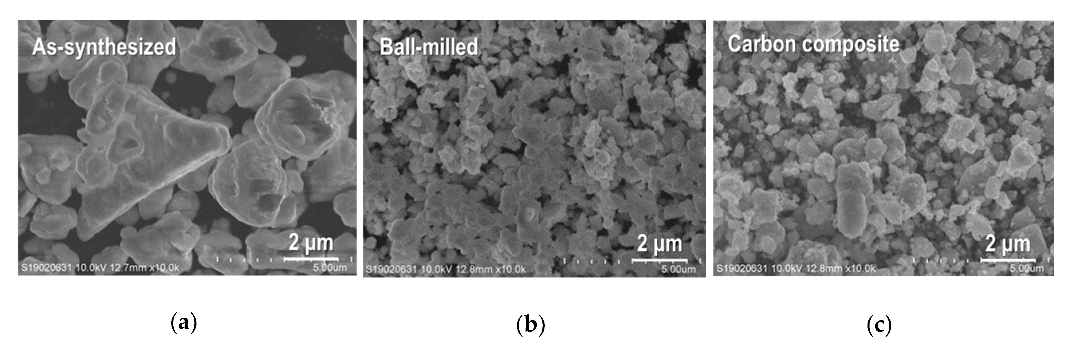
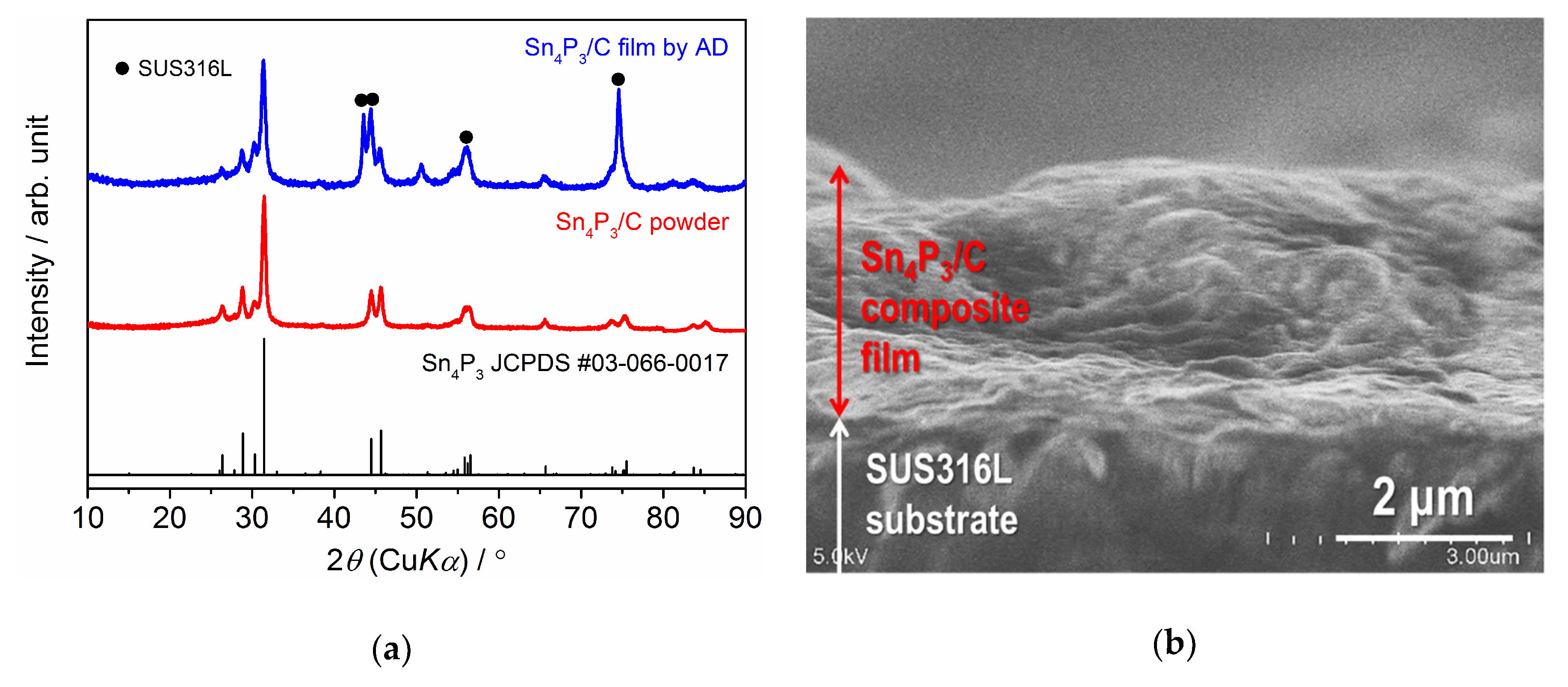
3.1. Crystal Phase and Microstructure of Sn4P3/C Composite Powder and Film

The XRD data for as-synthesized Sn4P3, ball-milled Sn4P3 and Sn4P3/C composite powders are summarized in Figure 1. The pattern for Sn4P3 (JCPDS No. 03-066-0017) is also shown as the reference. It is confirmed that peak patterns for all sample powders agree well with the reference, suggesting that any structural changes did not occur in the ball-milling and carbon-complexing process. No peaks from carbon were detected in the Sn4P3/C powder because complexed carbon with Sn4P3 has amorphous structure. Figure 2 shows scanning electron microscopy (SEM) images for as-synthesized Sn4P3, ball-milled Sn4P3 and Sn4P3/C composite powders. As-synthesized powder consists of agglomerated particles with a size of 1–5 µm (Figure 2a). After ball-milling, the particle size reduces to 0.5–1.5 µm (Figure 2b). On the other hand, after complexing carbon (acetylene black (AB)) with Sn4P3 by ball-milling, the particle size is not changed remarkably (Figure 2c).
A higher magnified SEM image of Sn4P3/C particles and elementary distributions for Sn, P and C in an observation area are shown in Figure 3. As shown in Figure 3a, the sample powder looks like agglomerated particles with a particle size of about 0.5–2 μm. Sn and P show similar distribution in an observed area and were detected on agglomerated particles, and interestingly, C is also distributed along the particle shape. This suggests that carbon (AB) particles are complexed successfully with Sn4P3 particles by a simple ball-milling process.
Figure 4 shows the XRD pattern and cross-sectional SEM image of the Sn4P3/C composite film formed on an SUS316L substrate by AD. Note that the peak intensity for the composite film is one order lower than the raw powder. Together with the peaks from the substrate, the peaks from the Sn4P3 phase are clearly confirmed but become broader compared to raw powder. No other secondary phases are formed during film fabrication by AD. The thickness of the composite film is confirmed to be 2.5–3 µm. An SEM image and elementary distributions for Sn, P and C for the broader surface of the Sn4P3/C composite film are shown in Figure 5. It can be seen that the film is composed of deformed or fractured particles. Moreover, Sn, P and C are distributed uniformly in an observed area, suggesting that carbon is included successfully in the film.

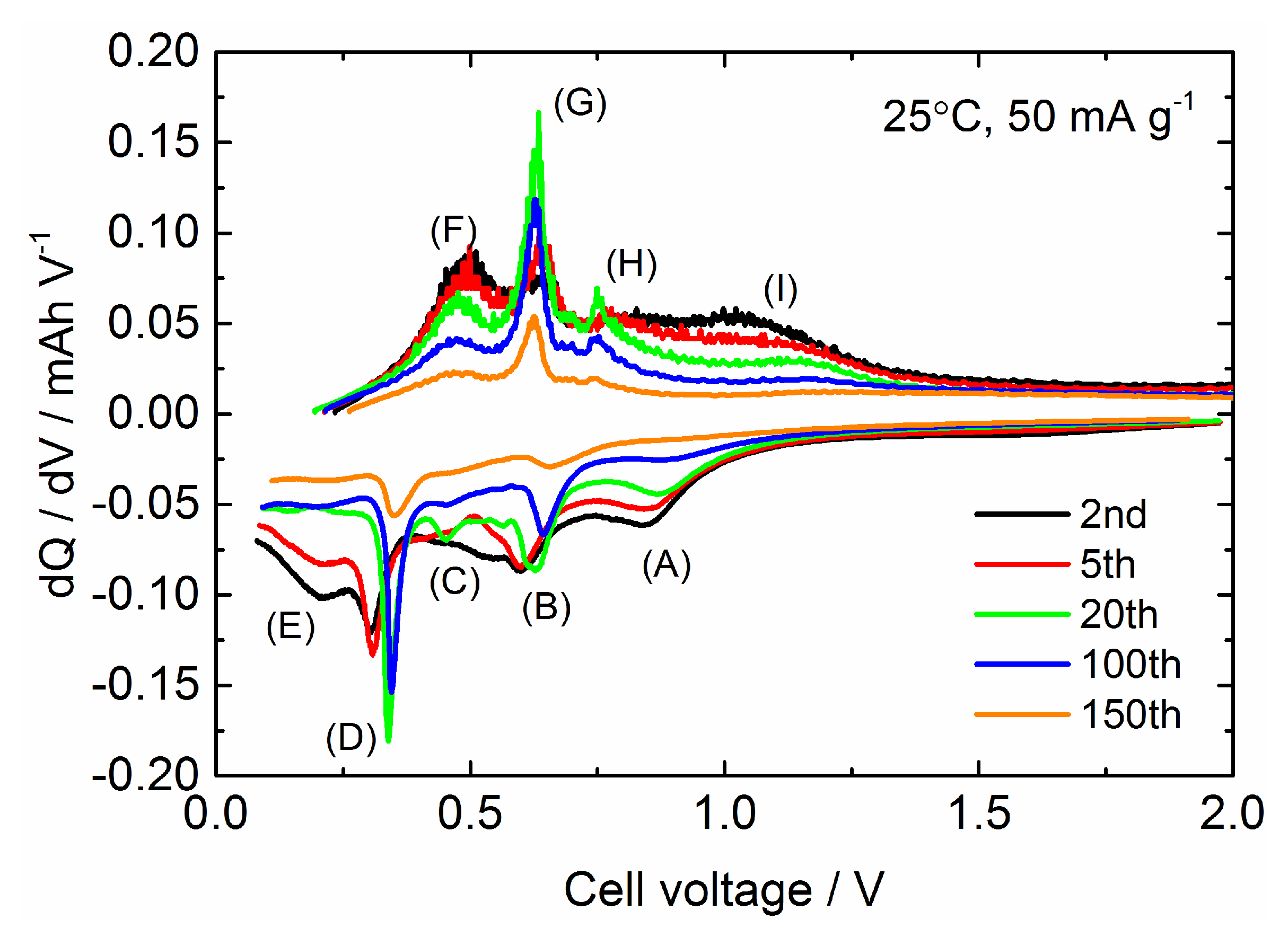
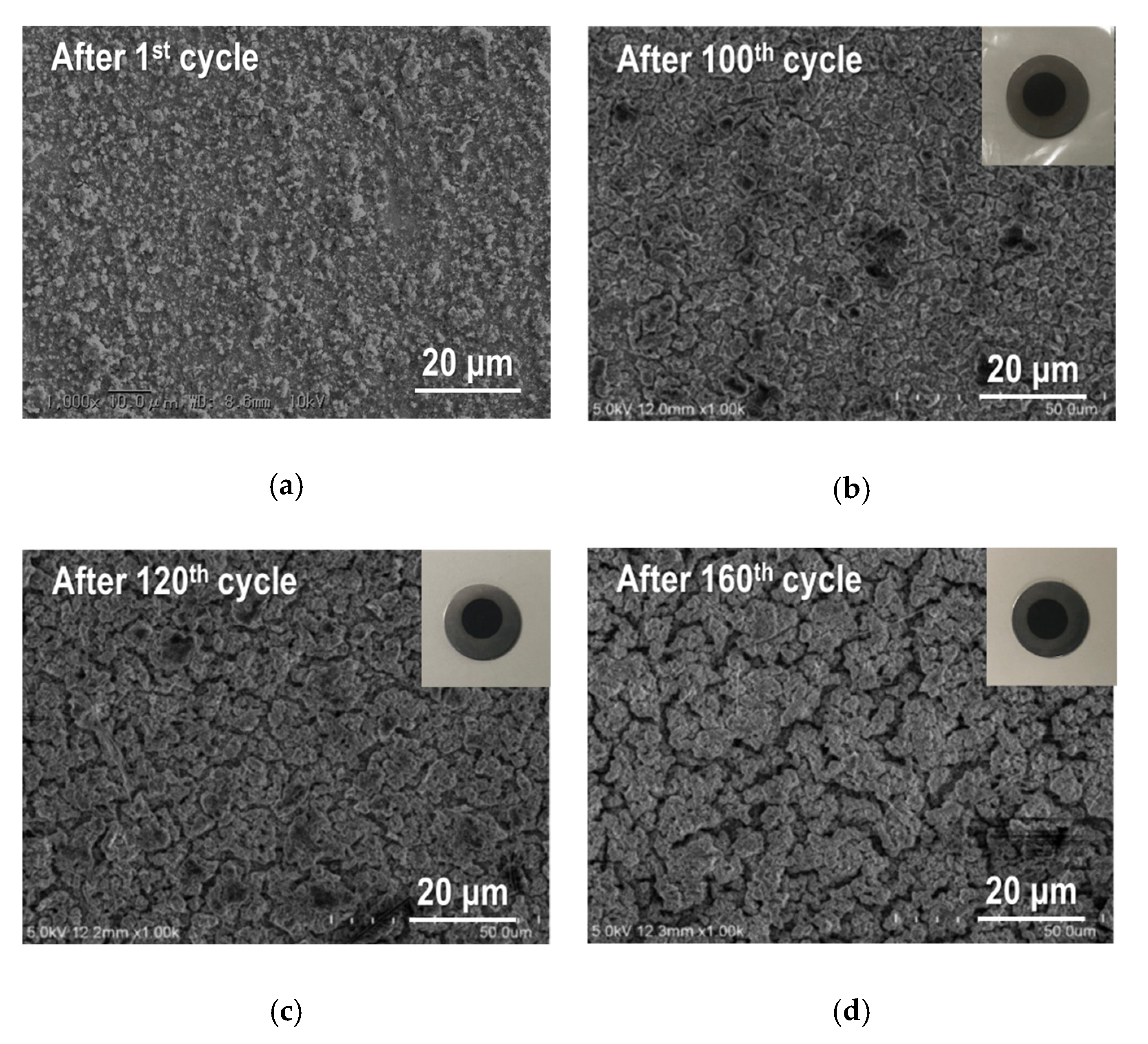
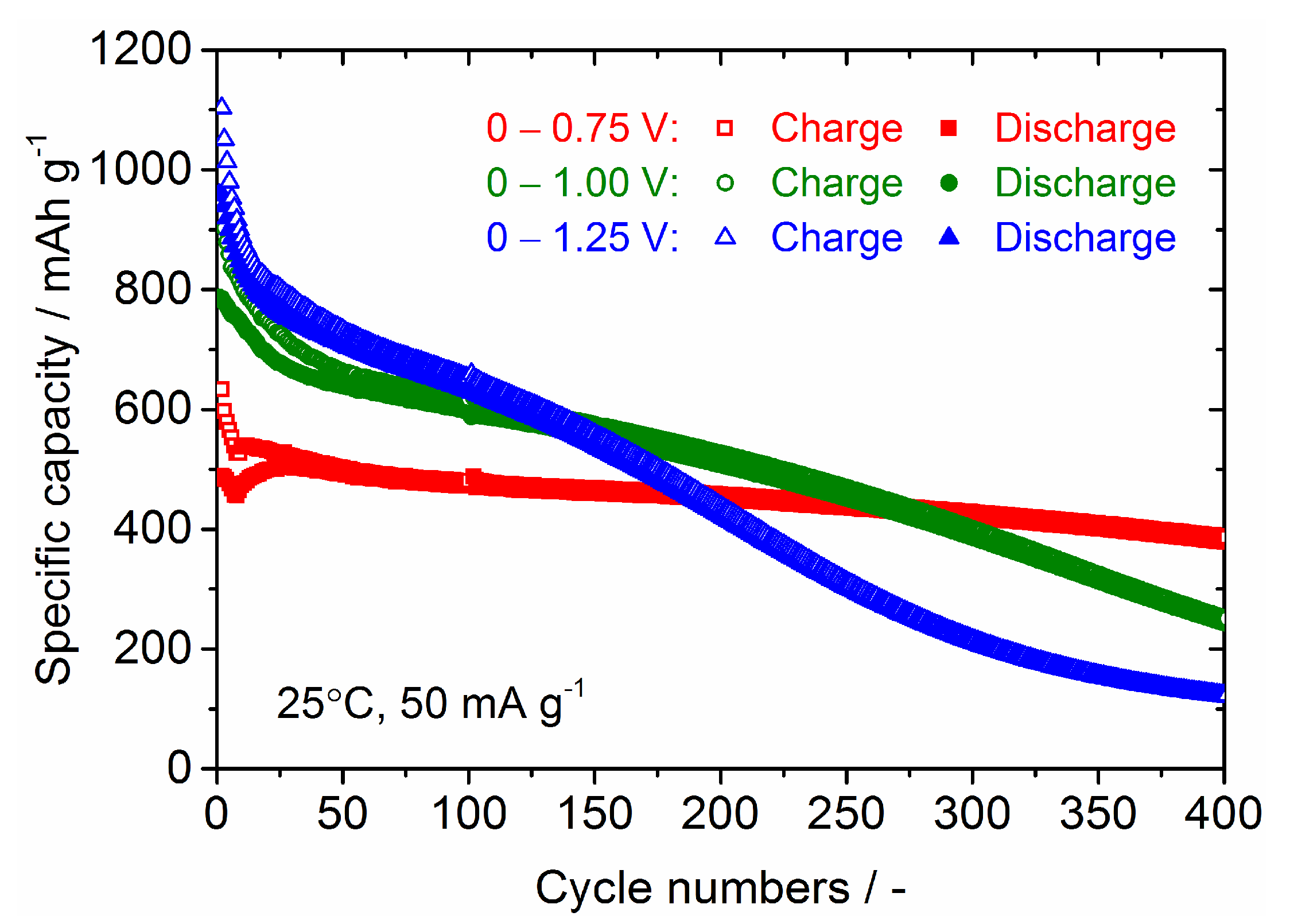
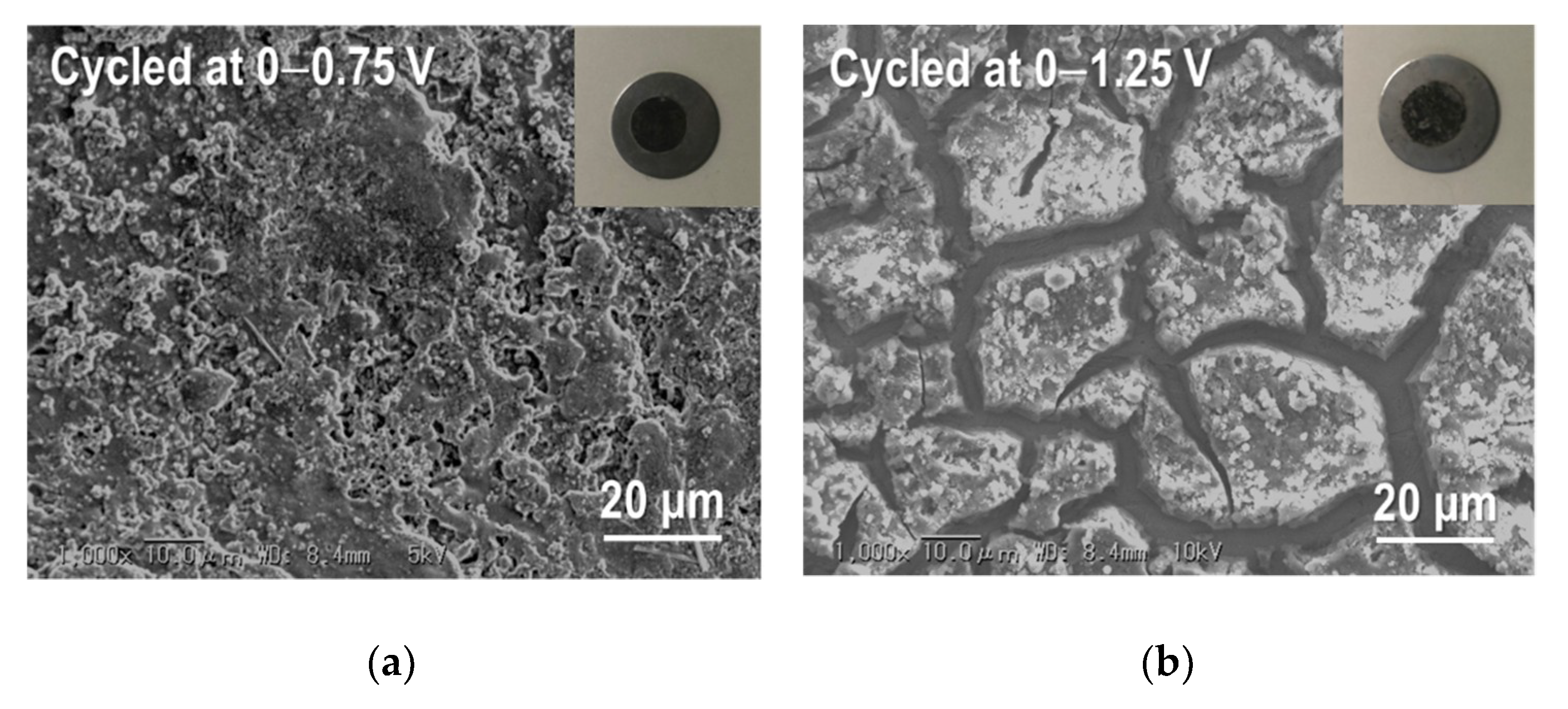
3.2. Electrochemical Performance of Sn4P3 Film Electrodes

Next, we discuss the electrochemical performance for Sn4P3/C composite film as a LiB anode. Figure 6 shows the galvanostatic charge (Li+ insertion) and discharge (Li+ extraction) curves at different cycle numbers for the Sn4P3/C film electrode in a coin-type cell. The cell voltage window is from 0 to 2.5 V. At the first cycle, charge capacity reaches 1750 mAh g−1, which is much higher than the theoretical capacity (1255 mAh g−1) of Sn4P3, while discharge capacity is confirmed to be 1200 mAh g−1. Coulombic efficiency at the first cycle is 69%, but irreversibility in charge and discharge reaction is greatly reduced after the second cycle and the Coulombic efficiency retains 96–98%. This suggests that the charge capacity in the first cycle includes the contribution of side reactions such as the decomposition of an organic liquid electrolyte at a lower cell voltage to form Li+ conducting solid-electrolyte interphase (SEI) on the electrode surface. The reversible capacity decreases monotonically with cycling but retains a high capacity of 800 mAh g−1 at the 50th cycle. The averaged operation potential is approximately 0.7 V and step-like profiles are confirmed in both charge and discharge processes, which is consistent with the results reported in the literature [8,9,10,11].
Cycling stability for the Sn4P3/C composite film electrode is shown in Figure 7, together with the data for the Sn4P3 film electrode without complexing carbon. The Sn4P3 film was fabricated by AD with ball-milled Sn4P3 powder (Figure 2b) on an SUS316L substrate, with a thickness of approximately 2 µm (Figure S1). As can be seen, the capacity fading in the Sn4P3 film with cycling is relatively fast and reduces to less than 10 mAh g−1 at the 80th cycle. We checked the Sn4P3 film taken from a disassembled coin-type cell after testing and confirmed that the majority of the film was collapsed and peeled off from the SUS316L substrate. Therefore, the rapid degradation of Sn4P3 films with cycling is caused by the mechanical damage due to the large volume change of the Sn4P3 film in charge and discharge reactions. On the other hand, the Sn4P3/C composite film shows much better cycling stability than the Sn4P3 film and retains a reversible capacity above 700 mAh g−1 even at the 100th cycle, indicating that the complexed carbon is effective at enhancing the cycling performance of Sn4P3. However, the capacity fading is accelerated by further cycling above 100 cycles and the reversible capacity is reduced to 300 mAh g−1 at the 200th cycle. It is worth noting that we also fabricated a Sn4P3/C composite film with a lower carbon content (weight ratio Sn4P3:C = 9:1) and evaluated the electrochemical performance, but the degradation with cycling becomes more significant and the reversible capacity at 100 cycles was reduced to 500 mAh g−1 (Figure S2).
As shown in Figure 7, the degradation mode of the Sn4P3/C composite film in galvanostatic cycling seems to be classified into three processes: (1) Rapid degradation below 15 cycles, (2) gradual degradation from 15 to 100 cycles, (3) accelerated degradation after 100 cycles. In order to further examine the degradation process, differential capacities dQ/dV (Q: capacity (mAh), V: cell voltage (V) are calculated and plotted against a cell voltage in Figure 8. Based on the examination of the electrochemical reaction mechanism for Sn4P3 anode characterized by ex-situ XRD and X-ray absorption spectroscopy (XAS) analysis in the literature [8], the reactions occurring in the charge process are considered as follows: (A) Li+ insertion into the layered structure of Sn4P3 (at ~0.85 V), (B) Formation of LiP and partial transformation from LiP to Li3P (at ~0.65 V), (C) and (D) Alloying of Sn with Li to form LixSn alloy (at ~0.5 V and ~0.3 V) and (E) Formation of Li3P and LixSn (at <0.25 V). On the other hand, reactions in the discharge process are considered as follows: (F) and (G) Dealloying reaction of LixSn (at ~0.45 V and ~0.65 V), (H) Dealloying reaction of LixSn and Li extraction to Li3P to form LiP (at ~0.75 V) and (I) Li extraction from LixP (at >0.8 V). Labels (A)–(H) for these expected reactions are also plotted in a graph.
In the range of 20 cycles or less, the contributions of (A) and (B) in charge and (I) in discharge decrease remarkably with cycling, while the reactivity of Sn for (D) and LixSn for (G) seems to be activated with cycling. After discharging, Sn4P3 is not completely formed reversibly but amorphous Sn and P are formed [8]. Moreover, it is demonstrated that the reversibility of the P LixP reaction is not good due to the large volume change and poor conductivity of the LiP phase [8,9,46,47], resulting in rapid capacity fading of the Sn4P3/C composite film during the initial 20 cycles. The dQ/dV profiles at the 20th and 100th cycle are similar but the peak intensity for (B), (C) and (D) in charge and (E), (G) and (H) in discharge decreases with the cycle progress. At the 150th cycle, these specific peaks in dQ/dV profile become smaller and broader compared to the profile at the 100th cycle.
For further examination, we fabricated another Sn4P3/C composite film to observe the change of the microstructure during the galvanostatic cycling. After the galvanostatic testing with different cycles, we took out the film electrodes of the disassembled cells and confirmed that all the films were not delaminated from the SUS316L substrates (see insets in Figure 9). SEM images for Sn4P3/C composite film after the first, 100th, 120th and 160th cycle are summarized in Figure 9. It is worth noting that capacity fading behavior with cycling for all Sn4P3/C films is nearly the same as the data shown in Figure 7. After the first cycle (Figure 9a), it can be seen that the asperities on the surface of the composite film are clearly increased compared to the as-deposited film (Figure 5a). This is caused by the large volume expansion and contraction in the charge and discharge reactions of active material. Such structural change is repeated during cycling and induces the gradual capacity fading with cycling. At the 100th cycle (Figure 9b), generation of many small cracks and agglomeration of the particles are confirmed and become significant with further cycling (Figure 9c,d). The former breaks the electrical conduction path and the latter reduces to electrochemical utilization of active materials in the composite film, resulting in acceleration of the degradation of reversible capacities after 100 cycles as shown in Figure 7.
The improvement of the cycling stability of the Sn4P3 anode has been demonstrated by controlling the cell voltage window in the literature but the cycle numbers were limited to only 50 [8,9], so we investigated the long-term cycling stability for Sn4P3/C composite films at different cell potential windows of 0–0.75 V, 0–1 V and 0–1.25 V. The galvanostatic charge and discharge curves at the 20th cycle and cycling performance for Sn4P3/C composite films tested at different cell potential windows are shown in Figure 10 and Figure 11. Although the reversible capacities at the 20th cycle reduce monotonically with decreasing cell voltage for discharge from 1.25 to 0.75 V, the cycling stability is dramatically improved. The film tested at 0–0.75 V shows a reversible capacity of 380 mAh g−1 at the 400th cycle and the capacity retention reaches 80%. The film electrodes tested at 0–1 V and 0–1.25 V also show higher reversible capacities of 400 and 500 mAh g−1 at the 200th cycle than the film tested at 0–2.5 V (300 mAh g−1, see Figure 7), but the capacity fading is accelerated with further cycling. Reversible capacities at the 400th cycle for the films tested at 0–1 V and 0–1.25 V are only 250 and 110 mAh g−1, respectively. By limiting the potential for discharge below 0.75 V, the extraction reaction of Li from LixP with a larger volume change is greatly suppressed, which could contribute to better cycling stability.
In Figure 12, the Coulombic efficiencies for Sn4P3/C composite films tested at different cell voltage windows are plotted against the cycle numbers. It can be seen that the efficiency for the initial several cycles becomes lower by reducing the cell voltage for discharging (Li extraction) from 1.25 to 0.75 V. This is mainly attributed to the reduction of the Li+ extraction reaction from LixP that occurred at a cell voltage above 0.8 V. After 20 cycles, the efficiencies for all films reached approximately 95%. After 40 cycles, the film tested at 0−0.75 V shows an efficiency as high as 97−98% and maintains it stably in whole measurement range. This is consistent with the good cycling stability of this film (Figure 11). On the other hand, the films tested at 0–1 V and 0–1.25 V show a slightly lower efficiency of 96−97% after 40 cycles.
For further examination, we took the Sn4P3/C composite film electrodes out of the disassembled cells after cycling at different cell voltage windows and observed their microstructures by SEM (Figure 13). As shown in Figure 13a, no delamination of the film from the SUS316L substrate was observed after cycling at 0–0.75 V. In addition, the structural change of the film cycled at 0–0.75 V is less than that for the film cycled at 0–1.25 V, which contributes to the better cycling performance. For the film cycled at 0–1.25 V with the lowest capacity retention (Figure 13b), delamination of many parts of the film from the substrate is confirmed and the large transversal cracks were generated at the location without peeling.
Lastly, we compare the electrochemical performance of some Sn4P3 anode materials for LiBs reported in the literature [8,9,11,14,15,16,17,20,21,22,23,24], which is listed in Table 1. It is worth noting that our current results reported in this paper are not the top performance for Sn4P3 anode materials for LiBs. As reported in [21], Sn4P3/C nanospheres synthesized by carbonization/reduction and phosphorization of SnO2–GCP (glucose-derived, carbon-rich polysaccharide) nanospheres showed an outstanding rate performance and cycling stability. These nanospheres can also be applicable for ultra-stable anode materials for sodium-ion batteries (SiBs). However, as mentioned above, the electrodes with these Sn4P3/C composite anode materials used in batteries are fabricated by a slurry coating process with a large amount of carbon additives and binders [20,21,22,23,24], resulting in the decrease of the fraction of Sn4P3 in the electrode. For the Sn4P3/C composite anode listed in Table 1, gravimetric capacities calculated by the total mass of electrode (including both carbon additives and binders) are 20−30% lower than the listed values. On the other hand, Sn4P3/C composite film electrodes formed by AD do not contain other carbon additives and binders, resulting in higher gravimetric capacity for the whole electrode. There is room to improve the electrochemical performance of the size and content of carbon materials for Sn4P3/C powders used for AD. We are now trying to optimize complexed carbon content and increase the composite film thickness and the progress will be reported in a forthcoming paper.

4. Conclusions

Sn4P3/C composite film was successfully fabricated by the AD method and its electrochemical performance for a lithium-ion battery anode was examined. The Sn4P3/C composite film fabricated by AD showed much better electrochemical performance than the Sn4P3 film without complexing carbon. Although both films showed initial discharge (Li+ extraction) capacities of approximately 900–1000 mAh g−1, Sn4P3/C films retained the higher reversible capacity above 700 mAh g−1 after 100 cycles of charge and discharge processes while the capacity of the Sn4P3 film rapidly degraded with cycling. Precise control of the potential window in galvanostatic testing of the Sn4P3/C composite film results in remarkable improvement in the cycling performance. We obtained a reversible capacity of approximately 400 mAh g−1 after 400 cycles by controlling the cell potential window, which is mainly attributed to the suppression of structural change of the film electrode during the cycling.

Supplementary Materials

The following are available online at https://www.mdpi.com/2079-4991/9/7/1032/s1, Figure S1: (a) SEM image of broader surface (left) and transverse cross section (right) of the Sn4P3 film fabricated by AD and (b) Galvanostatic charge and discharge curves for the Sn4P3 film, Figure S2: (a) Galvanostatic charge and discharge curves for the Sn4P3/C composite film (Sn4P3:AB = 9:1 in weight) and (b) Comparison of cycling stability for Sn4P3/C composite films with different carbon content.

Author Contributions

Conceptualization, T.M., Y.Y., and R.I.; methodology, T.M., Y.Y., and R.I.; validation, T.M., Y.Y., and R.I.; formal analysis, T.M, T.T., and R.I.; investigation, T.M., Y.Y., and R.I.; resources, R.I.; data curation, T.M. and R.I.; writing—original draft preparation, T.M. and R.I.; writing—review and editing, R.I.; visualization, T.M. and R.I.; supervision, Y.S.; project administration, R.I.; funding acquisition, R.I.

Funding

This research was funded in part by Grant-in-Aid for Scientific Research Grant Number 16K06218 and 16KK0127 from the Japan Society for the promotion of Science (JSPS). The article processing charge (APC) was supported by Toyohashi University of Technology Research Promotional Research Fund.

Acknowledgments

We would like to acknowledge the support of the Cooperative Research Facility Center at Toyohashi University of Technology.

Conflicts of Interest

The authors declare no conflict of interest. The funders had no role in the design of the study; in the collection, analyses, or interpretation of data; in the writing of the manuscript, or in the decision to publish the results.

References

  1. Kasavajjula, U.; Wang, C.; Appleby, A.J. Nano- and bulk-silicon-based insertion anodes for lithium-ion secondary cells. J. Power Sources 2007, 163, 1003–1039. [Google Scholar] [CrossRef]
  2. Winter, M.; Besenhard, J.O. Electrochemical lithiation of tin and tin-based intermetallics and composites. Electrochim. Acta 1999, 45, 31–50. [Google Scholar] [CrossRef]
  3. Zhang, W.J. A review of the electrochemical performance of alloy anodes for lithium-ion batteries. J. Power Sources 2011, 196, 13–24. [Google Scholar] [CrossRef]
  4. Idota, Y.; Kubota, T.; Matsufuji, A.; Maekawa, Y.; Miyasaka, T. Tin-based amorphous oxide: A high-capacity lithium-ion-storage material. Science 1997, 276, 1395–1397. [Google Scholar] [CrossRef]
  5. Besenhard, J.; Yang, J.; Winter, M. Will advanced lithium-alloy anodes have a chance in lithium-ion batteries? J. Power Sources 1997, 68, 87–90. [Google Scholar] [CrossRef]
  6. Kepler, K.D.; Vaughey, J.T.; Thackeray, M.M. LixCu6Sn5 (0 < x <13): An intermetallic insertion electrode for rechargeable lithium batteries. Electrochem. Solid-State Lett. 1999, 2, 307–309. [Google Scholar]
  7. Kim, H.; Choi, J.; Sohn, H.; Kang, T. The insertion mechanism of lithium into Mg2Si anode material for Li-ion batteries. J. Electrochem. Soc. 1999, 146, 4401–4405. [Google Scholar] [CrossRef]
  8. Kim, Y.U.; Lee, C.K.; Kang, T.; Sohn, H.J. Reaction mechanism of tin phosphide anode by mechanochemical method for lithium secondary batteries. J. Electrochem. Soc. 2004, 151, A933. [Google Scholar] [CrossRef]
  9. Kim, Y.; Lee, C.; Sohn, H.; Kang, T. Enhancement of capacity and cycle-life of Sn4+δP3 (0 ≤ δ ≤ 1) anode for lithium secondary batteries anode for lithium secondary batteries. J. Power Sources 2005, 141, 163–166. [Google Scholar] [CrossRef]
  10. León, B.; Corredor, J.I.; Pérez-Vicente, C.; Tirado, J.L.; Tirado, J.L. On the mechanism of the electrochemical reaction of tin phosphide with lithium. J. Electrochem. Soc. 2006, 153, A1829. [Google Scholar] [CrossRef]
  11. Wu, J.J.; Fu, Z.W. Pulsed-laser-deposited Sn4P3 electrodes for lithium-ion batteries. J. Electrochem. Soc. 2009, 156, A22. [Google Scholar] [CrossRef]
  12. Nazri, G. Preparation, structure and ionic conductivity of lithium phosphide. Solid State Ion. 1989, 34, 97–102. [Google Scholar] [CrossRef]
  13. Ueda, A.; Nagao, M.; Inoue, A.; Hayashi, A.; Seino, Y.; Ota, T.; Tatsumisago, M. Electrochemical performance of all-solid-state lithium batteries with Sn4P3 negative electrode. J. Power Sources 2013, 244, 597–600. [Google Scholar] [CrossRef]
  14. Liu, S.; Zhang, H.; Xu, L.; Ma, L. Synthesis of hollow spherical tin phosphides (Sn4P3) and their high adsorptive and electrochemical performance. J. Cryst. Growth 2016, 438, 31–37. [Google Scholar] [CrossRef]
  15. Liu, S.; Zhang, H.; Xu, L.; Ma, L.; Chen, X. Solvothermal preparation of tin phosphide as a long-life anode for advanced lithium and sodium ion batteries. J. Power Sources 2016, 304, 346–353. [Google Scholar] [CrossRef]
  16. Park, G.; Lee, C.; Lee, J.; Choi, J.H.; Lee, Y.S.; Lee, S.M. Effect of Fe substitution on electrochemical properties of Sn3.95Fe0.05P3 alloy anode for lithium ion batteries. J. Alloy. Compd. 2014, 588, 534–539. [Google Scholar] [CrossRef]
  17. Liu, S.; Zhang, H.; Xu, L.; Ma, L.; Hou, X. High lithium storage performance of Mn-doped Sn4P3 nanoparticles. Electrochim. Acta 2016, 210, 888–896. [Google Scholar] [CrossRef]
  18. Lin, J.; Kopold, P.; Wu, C.; van Aken, P.A.; Maiyer, J.; Yu, Y. Uniform yolk-shell Sn4P3@C nanospheres as high-capacity and cycle-stable anode materials for sodium-ion batteries. Energy Environ. Sci. 2015, 8, 3531–3538. [Google Scholar] [CrossRef]
  19. Fan, X.; Mao, J.; Zhu, Y.; Luo, C.; Suo, L.; Gao, T.; Han, F.; Liou, S.; Wang, C. Superior stable self-healing SnP3 anode for sodium-ion batteries. Nano. Lett. 2017, 17, 1870–1876. [Google Scholar] [CrossRef]
  20. Ding, Y.; Li, Z.; Tomofeeva, E.V.; Segre, C.U. In situ EXAFS−derived mechanism of highly reversible tin phosphide/graphite composite anode for Li-ion batteries. Adv. Mater. 2018, 8, 1702134. [Google Scholar] [CrossRef]
  21. Wang, X.; Kim, H.; Xiao, Y.; Sun, Y. Sn4P3–C nanospheres as high capacitive and ultra-stable anodes for sodium ion and lithium ion batteries. J. Mater. Chem. A 2018, 6, 17437–17443. [Google Scholar] [CrossRef]
  22. Xia, Y.; Han, S.; Zhu, Y.; Liang, Y.; Gu, M. Stable cycling of mesoporous Sn4P3/SnO2@C nanosphere anode with high initial coulombic efficiency for Li-ion batteries. Energy Storage Mater. 2019, 18, 125–132. [Google Scholar] [CrossRef]
  23. Jiang, Y.; Wang, Y.; Jiang, J.; Liu, S.; Li, W.; Huang, S.; Chen, Z.; Zhao, B. In-situ solvothermal phosphorization from nano-sized tetragonal-Sn to rhombohedral-Sn4P3 embedded in hollow graphene sphere with high capacity and stability. Electrochim. Acta 2019, 312, 263–271. [Google Scholar] [CrossRef]
  24. Zhang, M.; Wang, H.; Feng, J.; Chai, Y.; Luo, X.; Yuan, R.; Yang, X. Controllable synthesis of 3D nitrogen-doped carbon networks supported SnxPy nanoparticles as high performance anode for lithium ion batteries. Appl. Surf. Sci. 2019, 484, 899–905. [Google Scholar] [CrossRef]
  25. Gómez-Cámer, J.; Arnaiz, M.; Rojo, T.; Ajuria, J. Novel lithium-ion capacitor based on tin phosphide and olive pit derived activated carbon. J. Power Sources 2019, 434, 226695. [Google Scholar] [CrossRef]
  26. Akedo, J. Aerosol deposition of ceramic thick films at room temperature: densification mechanism of ceramic layers. J. Am. Ceram. Soc. 2006, 89, 1834–1839. [Google Scholar] [CrossRef]
  27. Akedo, J. Room temperature impact consolidation (RTIC) of fine ceramic powder by aerosol deposition method and applications to microdevices. J. Therm. Spray Technol. 2008, 17, 181–198. [Google Scholar] [CrossRef]
  28. Hanft, D.; Exner, J.; Schubert, M.; Thomas, S.; Fuierer, P.; Moos, R. An overview of the aerosol deposition method: Process fundamentals and new trends in materials applications. J. Ceram. Sci. Technol. 2015, 6, 147–182. [Google Scholar] [CrossRef]
  29. Usui, H.; Yamamoto, Y.; Yoshiyama, K.; Itoh, T.; Sakaguchi, H. Application of electrolyte using novel ionic liquid to Si thick film anode of Li-ion battery. J. Power Sources 2011, 196, 3911–3915. [Google Scholar] [CrossRef] [Green Version]
  30. Usui, H.; Shibata, M.; Nakai, K.; Sakaguchi, H. Anode properties of thick-film electrodes prepared by gas deposition of Ni-coated Si particles. J. Power Sources 2011, 196, 2143–2148. [Google Scholar] [CrossRef] [Green Version]
  31. Usui, H.; Sakata, T.; Shimizu, M.; Sakaguchi, H. Electrochemical Na-insertion/Extraction Properties of Sn–P Anodes. Electrochemistry 2015, 83, 810–812. [Google Scholar] [CrossRef]
  32. Takai, S.; Sakaguchi, H.; Tanaka, K.; Nagao, Y.; Esaka, T. Cathode Performance of LiMn2O4 thick films prepared by gas-deposition for lithium rechargeable battery. Electrochemistry 2008, 76, 293–296. [Google Scholar] [CrossRef]
  33. Kim, I.; Park, J.; Nam, T.H.; Kim, K.W.; Ahn, J.H.; Park, D.S.; Ahn, C.; Wang, G.; Ahn, H.J. Electrochemical properties of an as-deposited LiFePO4 thin film electrode prepared by aerosol deposition. J. Power Sources 2013, 244, 646–651. [Google Scholar] [CrossRef]
  34. Inada, R.; Shibukawa, K.; Masada, C.; Nakanishi, Y.; Sakurai, Y. Characterization of as-deposited Li4Ti5O12 thin film electrode prepared by aerosol deposition method. J. Power Sources 2014, 253, 181–186. [Google Scholar] [CrossRef]
  35. Iwasaki, S.; Hamanaka, T.; Yamakawa, T.; West, W.C.; Yamamoto, K.; Motoyama, M.; Hirayama, T.; Iriyama, Y. Preparation of thick-film LiNi1/3Co1/3Mn1/3O2 electrodes by aerosol deposition and its application to all-solid-state batteries. J. Power Sources 2014, 272, 1086–1090. [Google Scholar] [CrossRef]
  36. Kato, T.; Iwasaki, S.; Ishii, Y.; Motoyama, M.; West, W.C.; Yamamoto, Y.; Iriyama, Y.; Kato, T. Preparation of thick-film electrode-solid electrolyte composites on Li7La3Zr2O12 and their electrochemical properties. J. Power Sources 2016, 303, 65–72. [Google Scholar] [CrossRef]
  37. Ahn, C.W.; Choi, J.J.; Ryu, J.; Hahn, B.D.; Kim, J.W.; Yoon, W.H.; Choi, J.H.; Park, D.S. Microstructure and electrochemical properties of iron oxide film fabricated by aerosol deposition method for lithium ion battery. J. Power Sources 2015, 275, 336–340. [Google Scholar] [CrossRef]
  38. Inada, R.; Yasuda, S.; Tojo, M.; Tsuritani, K.; Tojo, T.; Sakurai, Y. Development of lithium-stuffed garnet-type oxide solid electrolytes with high ionic conductivity for application to all-solid-state batteries. Front. Energy Res. 2016, 4, 28. [Google Scholar] [CrossRef]
  39. Iriyama, Y.; Wadaguchi, M.; Yoshida, K.; Yamamoto, Y.; Motoyama, M.; Yamamoto, T. 5V-class bulk-type all-solid-state rechargeable lithium batteries with electrode-solid electrolyte composite electrodes prepared by aerosol deposition. J. Power Sources 2018, 385, 55–61. [Google Scholar] [CrossRef]
  40. Inada, R.; Okuno, K.; Kito, S.; Tojo, T.; Sakurai, Y. Properties of Lithium Trivanadate Film Electrodes Formed on Garnet-Type Oxide Solid Electrolyte by Aerosol Deposition. Materials 2018, 11, 1570. [Google Scholar] [CrossRef]
  41. Popovici, D.; Nagai, H.; Fujishima, S.; Akedo, J. Preparation of Lithium Aluminum Titanium Phosphate Electrolytes Thick Films by Aerosol Deposition Method. J. Am. Ceram. Soc. 2011, 94, 3847–3850. [Google Scholar] [CrossRef]
  42. Inada, R.; Ishida, K.I.; Tojo, M.; Okada, T.; Tojo, T.; Sakurai, Y. Properties of aerosol deposited NASICON-type Li1.5All0.5Ge1.5(PO4)3 solid electrolyte thin films. Ceram. Int. 2015, 41, 11136–11142. [Google Scholar] [CrossRef]
  43. Choi, J.-J.; Ahn, C.-W.; Ryu, J.; Hahn, B.-D.; Kim, J.-W.; Yoon, W.-H.; Park, D.-S. Li-ion conducting Li0.35La0.55TiO3 electrolyte thick films fabricated by aerosol deposition. J. Korean Phys. Soc. 2016, 68, 12–16. [Google Scholar] [CrossRef]
  44. Inada, R.; Okada, T.; Bando, A.; Tojo, T.; Sakurai, Y. Properties of garnet-type Li6La3ZrTaO12 solid electrolyte films fabricated by aerosol deposition method. Prog. Nat. Sci. 2017, 27, 350–355. [Google Scholar] [CrossRef]
  45. Hanft, D.; Exner, J.; Moos, R. Thick-films of garnet-type lithium ion conductor prepared by the Aerosol Deposition Method: The role of morphology and annealing treatment on the ionic conductivity. J. Power Sources 2017, 361, 61–69. [Google Scholar] [CrossRef]
  46. Park, C.M.; Sohn, H.J. Black phosphorus and its composite for lithium rechargeable batteries. Adv. Mater. 2007, 19, 2465–2468. [Google Scholar] [CrossRef]
  47. Tojo, T.; Yamaguchi, S.; Furukawa, Y.; Aoyanagi, K.; Umezaki, K.; Inada, R.; Sakurai, Y. Electrochemical performance of lithium ion battery anode using phosphorus encapsulated into nanoporous carbon nanotubes. J. Electrochem. Soc. 2018, 165, A1231–A1237. [Google Scholar] [CrossRef]
Figure 1. Comparison of X-ray diffraction (XRD) patterns for as-synthesized Sn4P3 powder, ball-milled Sn4P3 powder and Sn4P3/C composite powder.
Nanomaterials 09 01032 g001
Figure 2. Scanning electron microscopy (SEM) images for (a) as-synthesized Sn4P3 powder, (b) ball-milled Sn4P3 powder and (c) Sn4P3/C composite powder.
Nanomaterials 09 01032 g002
Figure 3. (a) SEM image of Sn4P3/C composite powder and corresponding element mapping for Sn, P and C are shown in (b), (c) and (d).
Nanomaterials 09 01032 g003
Figure 4. (a) XRD patterns for the Sn4P3/C composite powder and film formed on an SUS316L substrate and (b) cross-sectional SEM image for the Sn4P3/C composite film formed on an SUS316L substrate.
Nanomaterials 09 01032 g004
Figure 5. (a) SEM image of the broader surface of the Sn4P3/C composite film. Corresponding element mapping for Sn, P and C are shown in (b), (c) and (d).
Nanomaterials 09 01032 g005
Figure 6. Galvanostatic charge and discharge curves at different cycle numbers for the Sn4P3/C composite film electrode at 25 °C and 50 mA g−1. Cell voltage window for galvanostatic cycling is 0–2.5 V.
Nanomaterials 09 01032 g006
Figure 7. Comparison of cycling stability of charge and discharge capacities for the Sn4P3/C composite film and the Sn4P3 film electrodes. Cell voltage window for galvanostatic cycling is 0–2.5 V.
Nanomaterials 09 01032 g007
Figure 8. Differential capacity dQ/dV (Q: capacity, V: cell voltage) curves for the Sn4P3/C composite film calculated from the data for galvanostatic cycling test.
Nanomaterials 09 01032 g008
Figure 9. SEM images for the broader surface of Sn4P3/C composite films taken out of disassembled cells: (a) after the first cycle, (b) after the 100th cycle, (c) after the 120th cycle and (d) after the 160th cycle. Insets in (b), (c) and (d) are the photo images of films with different cycle numbers.
Nanomaterials 09 01032 g009
Figure 10. Comparison of galvanostatic charge (Li+ insertion) and discharge (Li+ extraction) curves at the 20th cycle for the Sn4P3/C composite film electrode tested at different cell voltage windows.
Nanomaterials 09 01032 g010
Figure 11. Cycling stability of charge and discharge capacities for the Sn4P3/C composite film tested at different cell voltage windows.
Nanomaterials 09 01032 g011
Figure 12. Coulombic efficiencies plotted against the cycle numbers for Sn4P3/C composite films tested at different cell voltage windows.
Nanomaterials 09 01032 g012
Figure 13. SEM images for the broader surface of Sn4P3/C composite films taken out of disassembled cells: (a) cycled at 0–0.75 V and (b) cycled at 0–1.25 V. Insets are the photo images of films.
Nanomaterials 09 01032 g013
Table 1. Comparison of electrochemical performance of some Sn4P3 anode materials for Li-ion batteries (LiB). AD: aerosol deposition.
SamplesCurrent Density/mA g−1Cycle NumbersSpecific Capacity/mAh g1References
Sn4P310050370[8]
Sn4+xP310050530 (x = 1)
430 (x = 0.5)
[9]
Sn4P3 film by pulsed laser deposition (PLD)0.2 mA cm−210553[11]
Fe doped Sn4P3100100420[14]
Mn doped Sn4P3100150488[15]
Sn4P310020261[16]
Sn4P3100300442[17]
Sn4P3/graphite100100651[20]
Sn4P3/C nanosphere200
2000
50
500
1050
440
[21]
Sn4P3/SnO2–C400200733[22]
Sn4P3/hollow graphene sphere100100606[23]
Sn4P3/N doped C100120718[24]
Sn4P3/C film by AD50100
400
726
380
This work

