A Sensitive Piezoresistive Tactile Sensor Combining Two Microstructures

 ,
, 

Abstract
1. Introduction
2. Materials and Methods
2.1. Nanocomposite
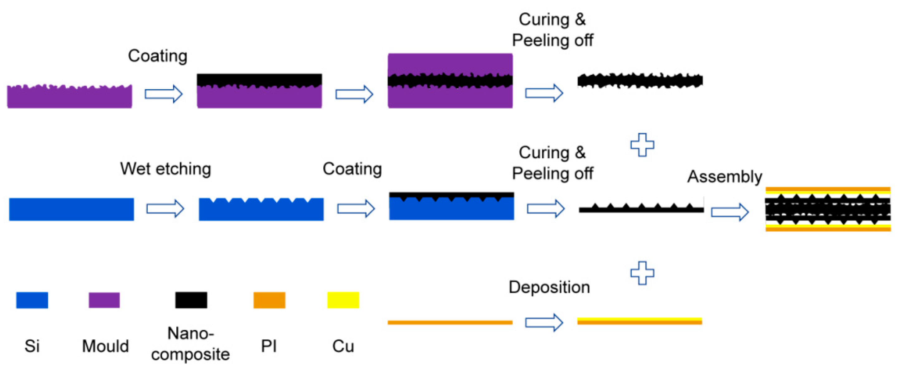
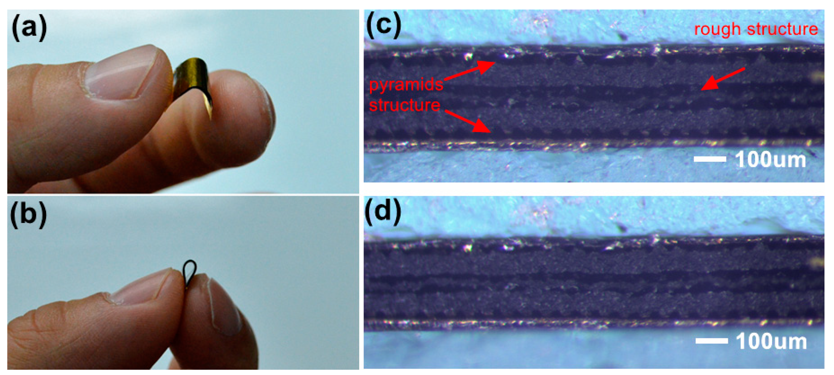
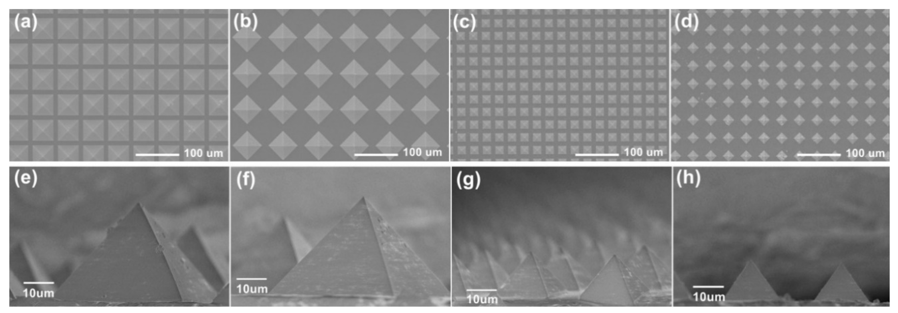
2.2. Fabrication
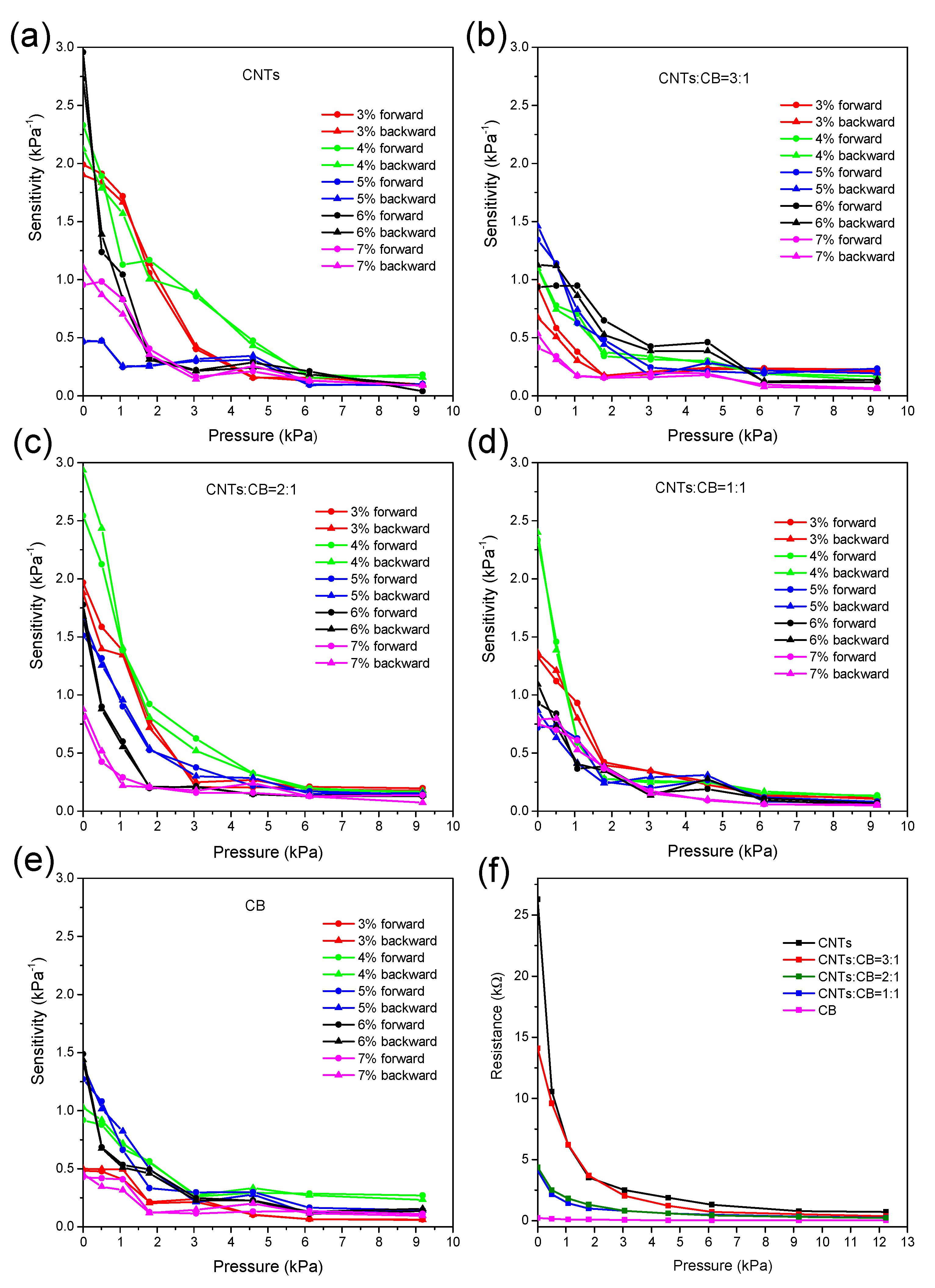
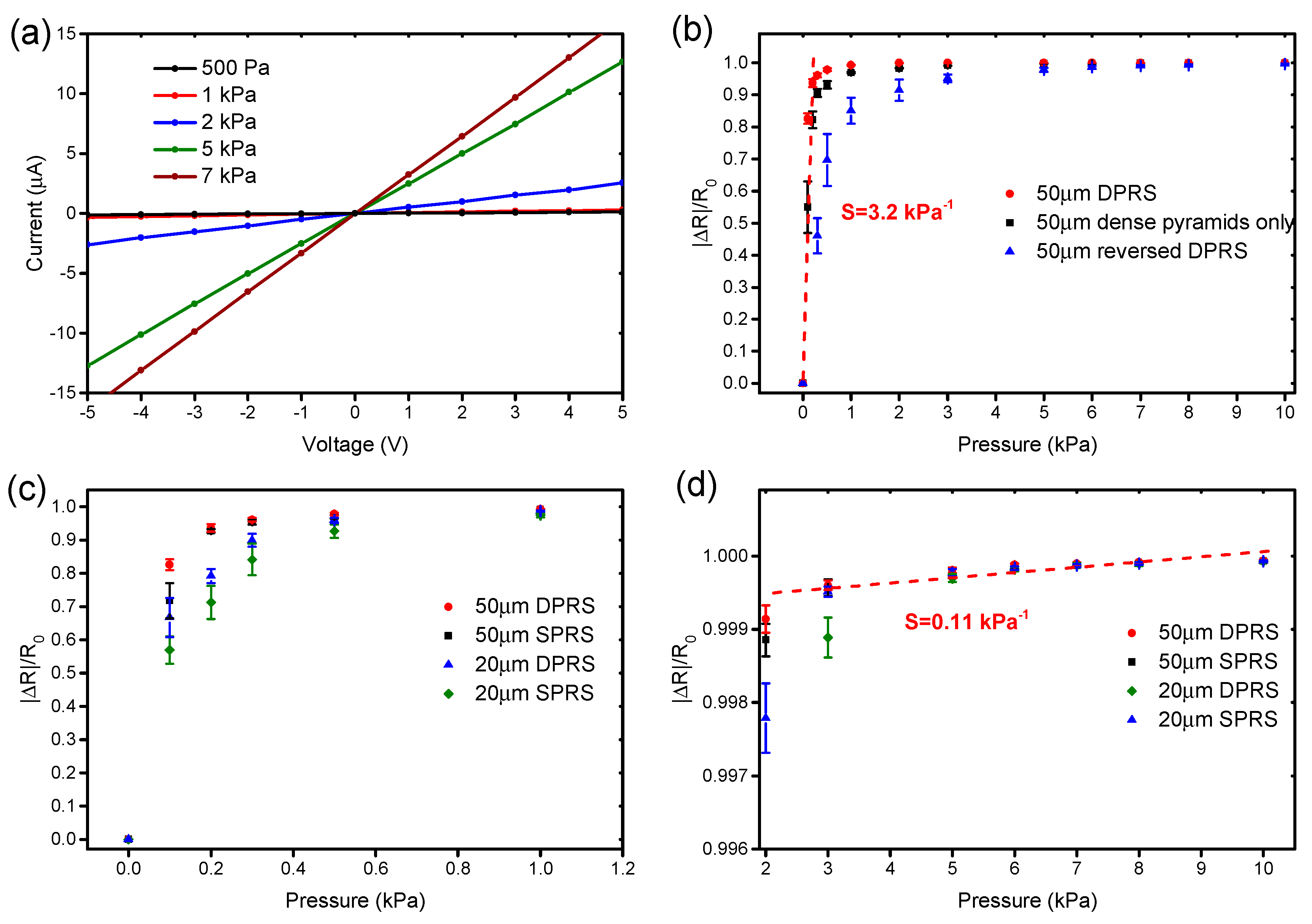
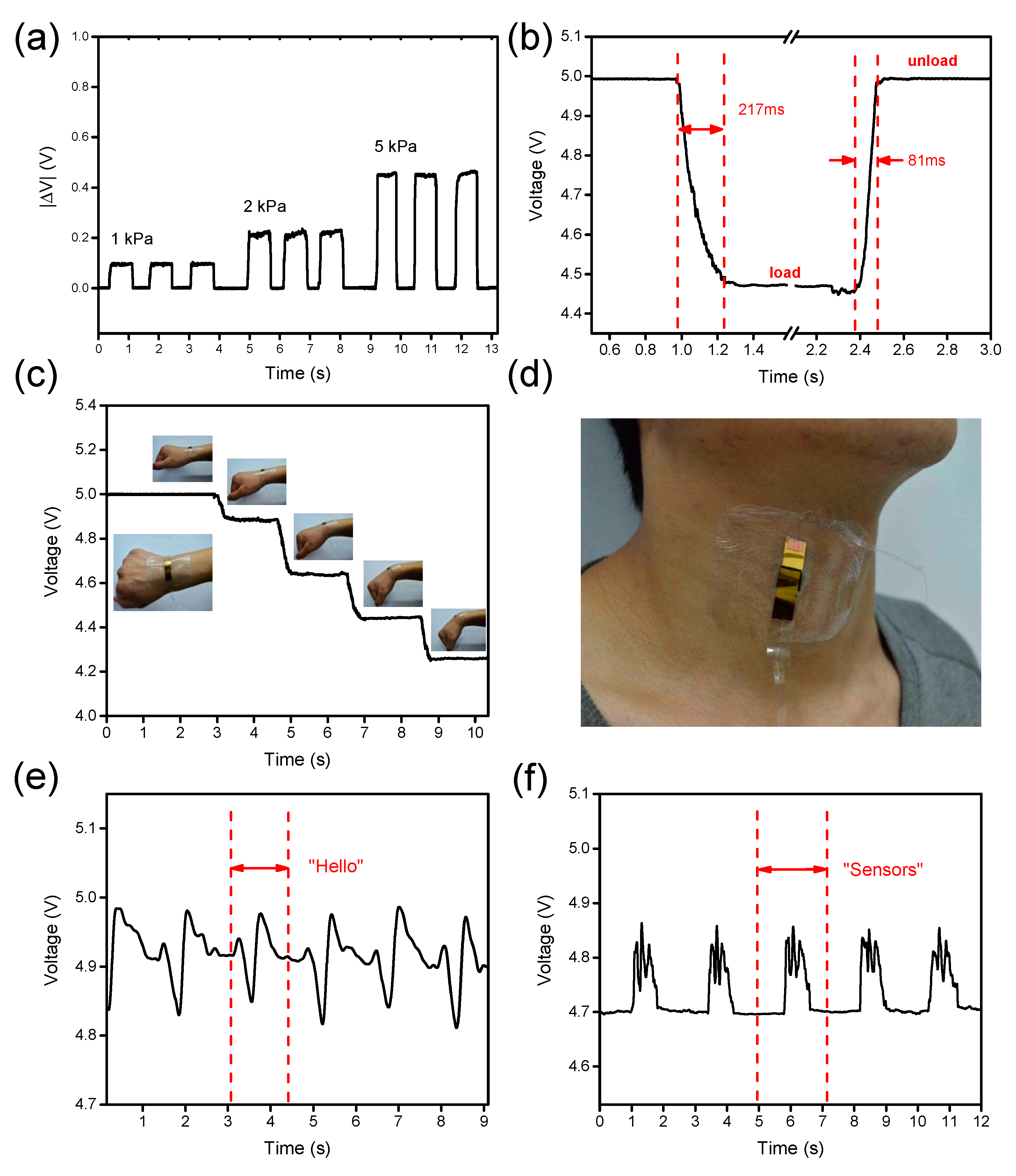
3. Results and Discussion
4. Conclusions
Author Contributions
Funding
Acknowledgments
Conflicts of Interest
References
- Honda, W.; Harada, S.; Arie, T.; Akita, S.; Takei, K. Wearable, human-interactive, health-monitoring, wireless devices fabricated by macroscale printing techniques. Adv. Funct. Mater. 2014, 24, 3299–3304. [Google Scholar] [CrossRef]
- Sekitani, T.; Someya, T. Stretchable organic integrated circuits for large-area electronic skin surfaces. MRS Bull. 2012, 37, 236–245. [Google Scholar] [CrossRef]
- Kim, J.; Lee, M.; Shim, H.J.; Ghaffari, R.; Cho, H.R.; Son, D.; Jung, Y.H.; Soh, M.; Choi, C.; Jung, S.; et al. For skin prosthesis. Nat. Commun. 2014, 5, 5747. [Google Scholar] [CrossRef] [PubMed]
- Wang, C.; Hwang, D.; Yu, Z.; Takei, K.; Park, J.; Chen, T.; Ma, B.; Javey, A. User-interactive electronic skin for instantaneous pressure visualization. Nat. Mater. 2013, 12, 899–904. [Google Scholar] [CrossRef] [PubMed]
- Dahiya, R.S.; Metta, G.; Valle, M.; Sandini, G. Tactile sensing-from humans to humanoids. IEEE Trans. Robot. 2010, 26, 1–20. [Google Scholar] [CrossRef]
- Pan, L.; Chortos, A.; Yu, G.; Wang, Y.; Isaacson, S.; Allen, R.; Shi, Y.; Dauskardt, R.; Bao, Z. An ultra-sensitive resistive pressure sensor based on hollow-sphere microstructure induced elasticity in conducting polymer film. Nat. Commun. 2014, 5, 3002. [Google Scholar] [CrossRef]
- Deng, W.; Jin, L.; Zhang, B.; Chen, Y.; Mao, L.; Zhang, H.; Yang, W. A flexible field-limited ordered ZnO nanorod-based self-powered tactile sensor array for electronic skin. Nanoscale 2016, 8, 16302–16306. [Google Scholar] [CrossRef] [PubMed]
- Xue, N.; Liu, C.; Sun, J.; Li, T.; Chi, C.; Hee, H.; Wang, Y. Miniature force sensing system for monitoring of optimal cricoid pressure for airway protection. IEEE Sens. J. 2018, 18, 4303–4310. [Google Scholar] [CrossRef]
- Chen, H.; Song, Y.; Guo, H.; Miao, L.; Chen, X.; Su, Z.; Zhang, H. Hybrid porous micro structured finger skin inspired self-powered electronic skin system for pressure sensing and sliding detection. Nano Energy 2018, 51, 496–503. [Google Scholar] [CrossRef]
- Bakar, A.A.A. Advances in bio-tactile sensors for minimally invasive surgery using the fibre Bragg grating force sensor technique: A survey. Sensors 2014, 14, 6633–6665. [Google Scholar]
- Alfadhel, A.; Kosel, J. Magnetic nanocomposite cilia tactile sensor. Adv. Mater. 2015, 27, 7888–7892. [Google Scholar] [CrossRef]
- Wang, X.; Gu, Y.; Xiong, Z.; Cui, Z.; Zhang, T. Silk-molded flexible, ultrasensitive, and highly stable electronic skin for monitoring human physiological signals. Adv. Mater. 2014, 26, 1336–1342. [Google Scholar] [CrossRef] [PubMed]
- Cao, Y.; Li, T.; Gu, Y.; Luo, H.; Wang, S.; Zhang, T. Fingerprint-inspired flexible tactile sensor for accurately discerning surface texture. Small 2018, 14, 1703902. [Google Scholar] [CrossRef]
- Zhu, B.; Niu, Z.; Wang, H.; Leow, W.R.; Wang, H.; Li, Y.; Zheng, L.; Wei, J.; Huo, F.; Chen, X. Microstructured graphene arrays for highly sensitive flexible tactile sensors. Small 2014, 10, 3625–3631. [Google Scholar] [CrossRef]
- Film, G.; Lü, X.; Yang, J.; Qi, L.; Bao, W.; Zhao, L.; Chen, R. High sensitivity flexible electronic skin based on. Sensors 2019, 19, 794. [Google Scholar]
- Loffredo, F.; Del Mauro, A.D.G.; Burrasca, G.; La Ferrara, V.; Quercia, L.; Massera, E.; Francia, G.D.; Sala, D. Della sensors and actuators B: Chemical ink-jet printing technique in polymer/carbon black sensing device fabrication. Sens. Actuators B Chem. 2009, 143, 421–429. [Google Scholar] [CrossRef]
- Zhang, J.; Zhou, L.J.; Zhang, H.M.; Zhao, Z.X.; Dong, S.L.; Wei, S.; Zhao, J.; Wang, Z.L.; Guo, B.; Hu, P.A. Highly sensitive flexible three-axis tactile sensors based on the interface contact resistance of microstructured graphene. Nanoscale 2018, 10, 7387–7395. [Google Scholar] [CrossRef] [PubMed]
- Li, T.; Luo, H.; Qin, L.; Wang, X.; Xiong, Z.; Ding, H.; Gu, Y.; Liu, Z.; Zhang, T. Flexible capacitive tactile sensor based on micropatterned dielectric layer. Small 2016, 12, 5042–5048. [Google Scholar] [CrossRef]
- Chun, S.; Hong, A.; Choi, Y.; Ha, C.; Park, W. A tactile sensor using a conductive graphene-sponge composite. Nanoscale 2016, 8, 9185–9192. [Google Scholar] [CrossRef]
- Han, Z.; Cheng, Z.; Chen, Y.; Li, B.; Liang, Z.; Li, H.; Ma, Y.; Feng, X. Fabrication of highly pressure-sensitive, hydrophobic, and flexible 3D carbon nanofiber networks by electrospinning for human physiological signal monitoring. Nanoscale 2019, 11, 5942–5950. [Google Scholar] [CrossRef]
- Kim, H.; Kim, G.; Kim, T.; Lee, S.; Kang, D.; Hwang, M.S.; Chae, Y.; Kang, S.; Lee, H.; Park, H.G.; et al. Transparent, flexible, conformal capacitive pressure sensors with nanoparticles. Small 2018, 14, 1703432. [Google Scholar] [CrossRef]
- Shao, Q.; Niu, Z.; Hirtz, M.; Jiang, L.; Liu, Y.; Wang, Z.; Chen, X. High-performance and tailorable pressure sensor based on ultrathin conductive polymer film. Small 2014, 10, 1466–1472. [Google Scholar] [CrossRef] [PubMed]
- Park, J.; Lee, Y.; Hong, J.; Ha, M.; Jung, Y.D.; Lim, H.; Ko, H. Giant tunneling piezoresistance of composite elastomers with interlocked microdome arrays for ultrasensitive and multimodal. ACS Nano 2014, 8, 4689–4697. [Google Scholar] [CrossRef] [PubMed]


| - | 3% | 4% | 5% | 6% | 7% |
|---|---|---|---|---|---|
| CNTs | 3 M | 2.2 M | 40 k | 25 k | 2.1 k |
| CNTs/CB = 3:1 | 475 k | 71 k | 20 k | 14 k | 1 k |
| CNTs/CB = 2:1 | 105 k | 27 k | 5.3 k | 4.1 k | 330 |
| CNTs/CB = 1:1 | 7 k | 2.9 k | 290 | 210 | 140 |
| CB | 526 k | 156 k | 5.8 k | 4 k | 300 |
| Sensing Materials | Sensing Mechanism | Pressure Sensitivity | Detection Range | Ref. |
|---|---|---|---|---|
| Carbon nanofiber networks | Piezoresistive | 1.41 kPa−1 | 4.5 kPa | [20] |
| Single-walled carbon nanotubes/PDMS | Piezoresistive | 3.26 kPa−1 | 3 kPa | [13] |
| Nanoparticles | Capacitive | 1.0 kPa−1 | 11 kPa | [21] |
| Conductive polymers | Piezoresistive | 17 kPa−1 | 5 kPa | [22] |
| CNT-PDMS composite | Piezoresistive | 15.1 kPa−1 | 59 kPa | [23] |
| Polystyrene microspheres | Capacitive | 0.815 kPa−1 | 500 kPa | [18] |
| MWCNTs-PDMS nanocomposite | Piezoresistive | 3.2 kPa−1 | 40 kPa | Our work |
© 2019 by the authors. Licensee MDPI, Basel, Switzerland. This article is an open access article distributed under the terms and conditions of the Creative Commons Attribution (CC BY) license (http://creativecommons.org/licenses/by/4.0/).
Share and Cite
Sun, X.; Sun, J.; Zheng, S.; Wang, C.; Tan, W.; Zhang, J.; Liu, C.; Liu, C.; Li, T.; Qi, Z.; et al. A Sensitive Piezoresistive Tactile Sensor Combining Two Microstructures. Nanomaterials 2019, 9, 779. https://doi.org/10.3390/nano9050779
Sun X, Sun J, Zheng S, Wang C, Tan W, Zhang J, Liu C, Liu C, Li T, Qi Z, et al. A Sensitive Piezoresistive Tactile Sensor Combining Two Microstructures. Nanomaterials. 2019; 9(5):779. https://doi.org/10.3390/nano9050779
Chicago/Turabian StyleSun, Xuguang, Jianhai Sun, Shuaikang Zheng, Chunkai Wang, Wenshuo Tan, Jingong Zhang, Chunxiu Liu, Chang Liu, Tong Li, Zhimei Qi, and et al. 2019. "A Sensitive Piezoresistive Tactile Sensor Combining Two Microstructures" Nanomaterials 9, no. 5: 779. https://doi.org/10.3390/nano9050779
APA StyleSun, X., Sun, J., Zheng, S., Wang, C., Tan, W., Zhang, J., Liu, C., Liu, C., Li, T., Qi, Z., & Xue, N. (2019). A Sensitive Piezoresistive Tactile Sensor Combining Two Microstructures. Nanomaterials, 9(5), 779. https://doi.org/10.3390/nano9050779