Dual Carbonaceous Materials Synergetic Protection Silicon as a High-Performance Free-Standing Anode for Lithium-Ion Battery

Abstract
1. Introduction
2. Materials and Methods
2.1. Materials
2.2. Synthesis of Poly Diallyl Dimethy Lammonium Chlorid -Coated Si (PDDA@Si)
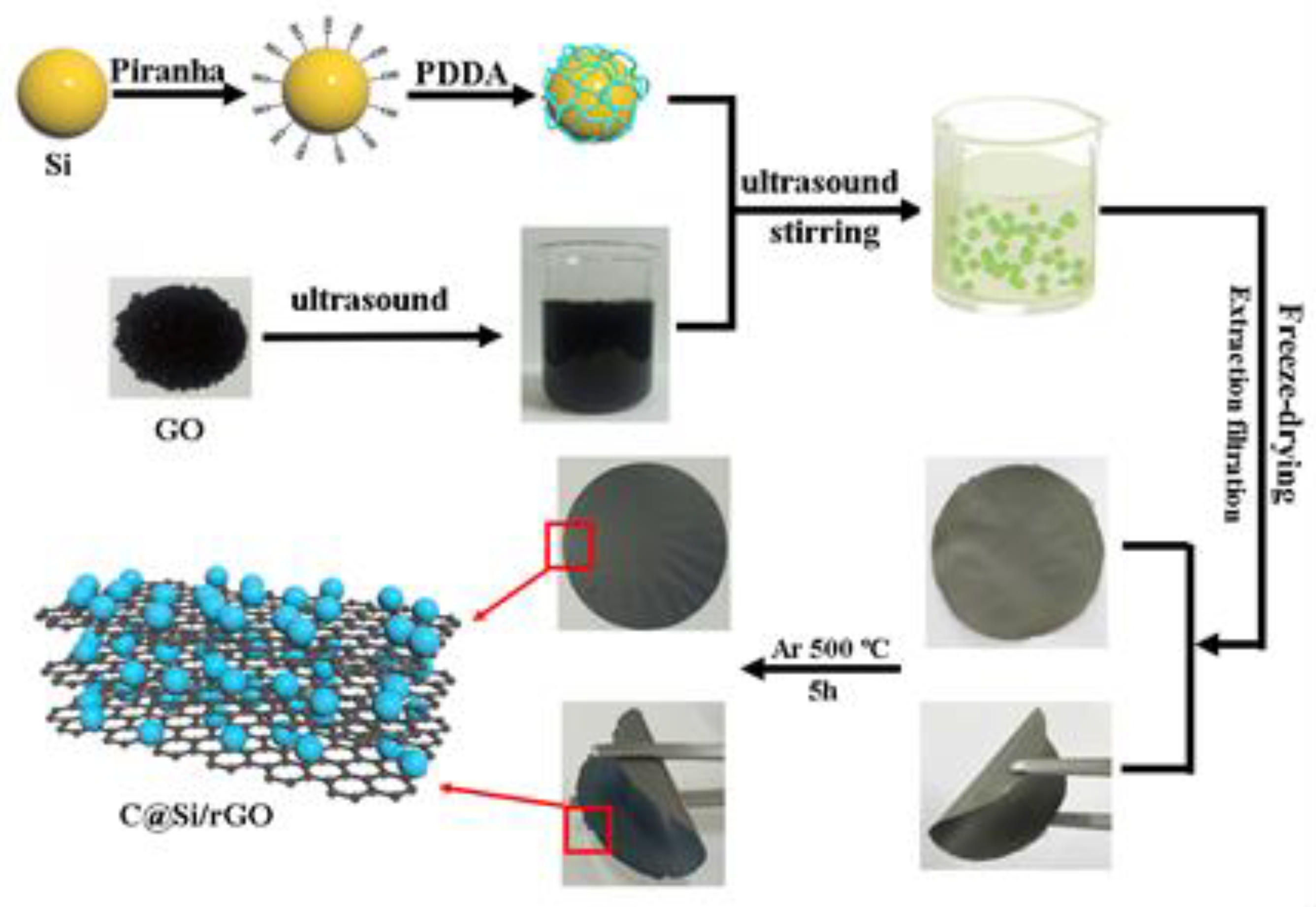
2.3. Synthesis of Carbon Coated Si/rGO Composite Film (C@Si/rGO) by Electrostatic Self-Assembly
2.4. Characterization
2.5. Electrochemical Tests
3. Results
4. Conclusions
Supplementary Materials
Author Contributions
Funding
Acknowledgments
Conflicts of Interest
References
- Goodenough, J.B.; Kim, Y. Challenges for rechargeable Li batteries. Chem. Mater. 2010, 22, 587–603. [Google Scholar] [CrossRef]
- Lee, W.W.; Lee, J.M. Novel synthesis of high performance anode materials for lithium-ion batteries (LIBs). J. Mater. Chem. A 2014, 2, 1589–1626. [Google Scholar] [CrossRef]
- Yoo, H.D.; Markevich, E.; Salitra, G.; Sharon, D.; Aurbach, D. On the challenge of developing advanced technologies for electrochemical energy storage and conversion. Mater. Today 2014, 17, 110–121. [Google Scholar] [CrossRef]
- Goodenough, J.B. How we made the Li-ion rechargeable battery. Nature Electron. 2018, 1, 204. [Google Scholar] [CrossRef]
- Fergus, J.W. Recent developments in cathode materials for lithium ion batteries. J. Power Sources 2010, 195, 939–954. [Google Scholar] [CrossRef]
- Li, H.; Wang, Z.; Chen, L.; Huang, X. Research on advanced materials for Li-ion batteries. Adv. Mater. 2009, 21, 4593–4607. [Google Scholar] [CrossRef]
- Liu, N.; Wu, H.; McDowell, M.T.; Yao, Y.; Wang, C.; Cui, Y. A yolk-shell design for stabilized and scalable li-ion battery alloy anodes. Nano Lett. 2012, 12, 3315–3321. [Google Scholar] [CrossRef] [PubMed]
- Wang, M.S.; Wang, Z.Q.; Chen, Z.; Yang, Z.L.; Tang, Z.L.; Luo, H.Y.; Huang, Y.; Li, X.; Xu, W. One dimensional and coaxial polyaniline@tin dioxide@multi-wall carbon nanotube as advanced conductive additive free anode for lithium ion battery. Chem. Eng. J. 2018, 334, 162–171. [Google Scholar] [CrossRef]
- Zhou, X.S.; Yin, Y.X.; Wan, L.J.; Guo, Y.G. Self-Assembled Nanocomposite of silicon nanoparticles encapsulated in graphene through electrostatic attraction for lithium-ion batteries. Adv. Energy Mater. 2012, 2, 1086–1090. [Google Scholar] [CrossRef]
- Li, X.; Zhang, K.; Mitlin, D.; Yang, Z.; Wang, M.; Tang, Y.; Jiang, F.; Du, Y.; Zheng, J. Fundamental insight into Zr modification of Li- and Mn-rich cathodes: combined transmission electron microscopy and electrochemical impedance spectroscopy study. Chem. Mater. 2018, 30, 2566–2573. [Google Scholar] [CrossRef]
- Pan, Q.; Zuo, P.; Lou, S.; Mu, T.; Du, C.; Cheng, X.; Ma, Y.; Gao, Y.; Yin, G. Micro-sized spherical silicon@carbon@graphene prepared by spray drying as anode material for lithium-ion batteries. J. Alloys Compd. 2017, 723, 434–440. [Google Scholar] [CrossRef]
- Luo, Z.; Xiao, Q.; Lei, G.; Li, Z.; Tang, C. Si nanoparticles/graphene composite membrane for high performance silicon anode in lithium ion batteries. Carbon 2016, 98, 373–380. [Google Scholar] [CrossRef]
- Fang, M.; Wang, Z.; Chen, X.; Guan, S. Sponge-like reduced graphene oxide/silicon/carbon nanotube composites for lithium ion batteries. Appl. Surf. Sci. 2018, 436, 345–353. [Google Scholar] [CrossRef]
- Ru, Y.; Evans, D.G.; Zhu, H.; Yang, W. Facile fabrication of yolk–shell structured porous Si–C microspheres as effective anode materials for Li-ion batteries. RSC Adv. 2014, 4, 71–75. [Google Scholar] [CrossRef]
- Yao, W.; Cui, Y.; Zhan, L.; Chen, F.; Zhang, Y.; Wang, Y.; Song, Y. Two-dimensional sandwich-like Ag coated silicon-graphene-silicon nanostructures for superior lithium storage. Appl. Surf. Sci. 2017, 425, 614–621. [Google Scholar] [CrossRef]
- Wang, G.; Xu, B.; Shi, J.; Lei, X.; Ouyang, C. Confined Li ion migration in the silicon-graphene complex system: An ab initio investigation. Appl. Surf. Sci. 2018, 436, 505–510. [Google Scholar] [CrossRef]
- Wang, M.S.; Song, W.L.; Fan, L.Z. Three-dimensional interconnected network of graphene-wrapped silicon/carbon nanofiber hybrids for binder-free anodes in lithium-ion batteries. ChemElectroChem 2015, 2, 1699–1706. [Google Scholar] [CrossRef]
- Lu, Z.; Li, B.; Yang, D.; Lv, H.; Xue, M.; Zhang, C. A self-assembled silicon/phenolic resin-based carbon core–shell nanocomposite as an anode material for lithium-ion batteries. RSC Adv. 2018, 8, 3477–3482. [Google Scholar] [CrossRef]
- Su, M.; Wan, H.; Liu, Y.; Xiao, W.; Dou, A.; Wang, Z.; Guo, H. Multi-layered carbon coated Si-based composite as anode for lithium-ion batteries. Powder Technol. 2018, 323, 294–300. [Google Scholar] [CrossRef]
- Yao, W.; Chen, J.; Zhan, L.; Wang, Y.; Yang, S. Two-dimensional porous sandwich-like C/Si-graphene-Si/C nanosheets for superior lithium storage. ACS Appl. Mater. Interfaces 2017, 9, 39371–39379. [Google Scholar] [CrossRef] [PubMed]
- Zhai, W.; Ai, Q.; Chen, L.; Wei, S.; Li, D.; Zhang, L.; Si, P.; Feng, J.; Ci, L. Walnut-inspired microsized porous silicon/graphene core–shell composites for high-performance lithium-ion battery anodes. Nano Res. 2017, 10, 4274–4283. [Google Scholar] [CrossRef]
- Li, X.; Tang, Y.; Song, J.; Yang, W.; Wang, M.; Zhu, C.; Zhao, W.; Zheng, J.; Lin, Y. Self-supporting activated carbon/carbon nanotube/reduced graphene oxide flexible electrode for high performance supercapacitor. Carbon 2018, 129, 236–244. [Google Scholar] [CrossRef]
- Chen, C.; Wu, M.; Wang, S.; Yang, J.; Qin, J.; Peng, Z.; Feng, T.; Gong, F. An in situ iodine-doped graphene/silicon composite paper as a highly conductive and self-supporting electrode for lithium-ion batteries. RSC Adv. 2017, 7, 38639–38646. [Google Scholar] [CrossRef]
- Wu, P.F.; Guo, C.Q.; Han, J.T.; Yu, K.R.; Dong, X.C.; Yue, G.H.; Yue, H.J.; Guan, Y.; Liu, A.H. Fabrication of double core–shell Si-based anode materials with nanostructure for lithium-ion battery. RSC Adv. 2018, 8, 9094–9102. [Google Scholar] [CrossRef]
- Chen, Y.L.; Hu, Y.; Shen, Z.; Chen, R.Z.; He, X.; Zhang, X.W.; Li, Y.Q.; Wu, K.S. Hollow core-shell structured silicon@carbon nanoparticles embed in carbon nanofibers as binder-free anodes for lithium-ion batteries. J. Power Sources 2017, 342, 467–475. [Google Scholar] [CrossRef]
- Li, Y.; Chang, B.; Li, T.T.; Kang, L.T.; Xu, S.D.; Zhang, D.; Xie, L.L.; Liang, W. One-step synthesis of hollow structured Si/C composites based on expandable microspheres as anodes for lithium ion batteries. Electrochem. Commun. 2016, 72, 69–73. [Google Scholar] [CrossRef]
- Wang, T.; Wang, F.H.; Zhu, H. Hollow core-shell-structured Si-C composites as high-performance anodes for lithium-ion batteries. Mater. Lett. 2015, 161, 89–92. [Google Scholar] [CrossRef]
- Wang, M.S.; Wang, Z.Q.; Jia, R.; Yang, Z.L.; Yang, Y.; Zhu, F.Y.; Huang, Y.; Li, X. Nano tin dioxide anchored onto carbon nanotube/graphene skeleton as anode material with superior lithium-ion storage capability. J. Electroanal. Chem. 2018, 815, 30–39. [Google Scholar] [CrossRef]
- Dey, A.; Bajpai, O.P.; Sikder, A.K.; Chattopadhyay, S.; Khan, M.A.S. Recent advances in CNT/graphene based thermoelectric polymer nanocomposite: A proficient move towards waste energy harvesting. Renew. Sust. Energ. Rev. 2016, 53, 653–671. [Google Scholar] [CrossRef]
- Oh, S.Y.; Oh, M.K.; Kang, T.J. Characterization and electrorheological response of silica/titania-coated MWNTs synthesized by sol–gel process. Colloid. Surface. A 2013, 436, 354–362. [Google Scholar] [CrossRef]
- Abnavi, A.; Faramarzi, M.S.; Abdollahi, A.; Ramzani, R.; Ghasemi, S.; Sanaee, Z. SnO2@a-Si core–shell nanowires on free-standing CNT paper as a thin and flexible Li-ion battery anode with high areal capacity. Nanotechnology 2017, 28, 255404. [Google Scholar] [CrossRef]
- Suresh, S.; Wu, Z.P.; Bartolucci, S.F.; Basu, S.; Mukherjee, R.; Gupta, T.; Hundekar, P.; Shi, Y.; Lu, T.M.; Koratkar, N. Protecting silicon film anodes in lithium-ion batteries using an atomically thin graphene drape. ACS Nano 2017, 11, 5051–5061. [Google Scholar] [CrossRef] [PubMed]
- Chang, J.; Huang, X.; Zhou, G.; Cui, S.; Hallac, P.B.; Jiang, J.; Hurley, P.T.; Chen, J. Multilayered Si nanoparticle/reduced graphene oxide hybrid as a high-performance lithium-ion battery anode. Adv. Mater. 2014, 26, 758–764. [Google Scholar] [CrossRef] [PubMed]
- Wang, B.; Li, X.; Luo, B.; Jia, Y.; Zhi, L. One-dimensional/two-dimensional hybridization for self-supported binder-free silicon-based lithium ion battery anodes. Nanoscale 2013, 5, 1470–1474. [Google Scholar] [CrossRef]
- Xin, X.; Zhou, X.; Wang, F.; Yao, X.; Xu, X.; Zhu, Y.; Liu, Z. A 3D porous architecture of Si/graphene nanocomposite as high-performance anode materials for Li-ion batteries. J. Mater. Chem. 2012, 22, 7724–7730. [Google Scholar] [CrossRef]
- Mi, H.; Li, F.; Xu, S.; Li, Z.; Chai, X.; He, C.; Li, Y.; Liu, J. A Tremella-like nanostructure of silicon@void@graphene-like nanosheets cmposite as an anode for lithium-ion batteries. Nanoscale Res. Lett. 2016, 11, 204–212. [Google Scholar] [CrossRef]
- Li, Y.; Yan, K.; Lee, H.-W.; Lu, Z.; Liu, N.; Cui, Y. Growth of conformal graphene cages on micrometre-sized silicon particles as stable battery anodes. Nat. Energy 2016, 1, 15029–15036. [Google Scholar] [CrossRef]
- Chen, S.; Shen, L.; van Aken, P.A.; Maier, J.; Yu, Y. Dual-functionalized double carbon shells coated silicon nanoparticles for high performance lithium-ion batteries. Adv. Mater. 2017, 29, 1605650–1605658. [Google Scholar] [CrossRef]
- Li, P.; Zhang, K.; Park, J.H. Dual or multi carbonaceous coating strategies for next-generation batteries. J. Mater. Chem. A 2018, 6, 1900–1914. [Google Scholar] [CrossRef]
- Cai, H.; Han, K.; Jiang, H.; Wang, J.; Liu, H. Self-standing silicon-carbon nanotube/graphene by a scalable in situ approach from low-cost Al-Si alloy powder for lithium ion batteries. J. Phys. Chem. Solids 2017, 109, 9–17. [Google Scholar] [CrossRef]
- Ma, X.; Hou, G.; Ai, Q.; Zhang, L.; Si, P.; Feng, J.; Ci, L. A heart-coronary arteries structure of carbon nanofibers/graphene/silicon composite anode for high performance lithium ion batteries. Sci. Rep. 2017, 7, 9642–9649. [Google Scholar] [CrossRef] [PubMed]
- Tao, H.; Xiong, L.; Zhu, S.; Yang, X.; Zhang, L. Flexible binder-free reduced graphene oxide wrapped Si/carbon fibers paper anode for high-performance lithium ion batteries. Int. J. Hydrogen Energy 2016, 41, 21268–21277. [Google Scholar] [CrossRef]
- Li, N.; Zhou, G.; Li, F.; Wen, L.; Cheng, H.-M. A Self-Standing and Flexible Electrode of Li4Ti5O12 Nanosheets with a N-Doped Carbon Coating for High Rate Lithium Ion Batteries. Adv. Funct. Mater. 2013, 23, 5429–5435. [Google Scholar] [CrossRef]
- Chen, Y.; Choi, S.; Su, D.; Gao, X.; Wang, G. Self-standing sulfur cathodes enabled by 3D hierarchically porous titanium monoxide-graphene composite film for high-performance lithium-sulfur batteries. Nano Energy 2018, 47, 331–339. [Google Scholar] [CrossRef]
- Choudhury, A.; Kim, J.-H.; Yang, K.-S.; Yang, D.-J. Facile synthesis of self-standing binder-free vanadium pentoxide-carbon nanofiber composites for high-performance supercapacitors. Electrochim. Acta 2016, 213, 400–407. [Google Scholar] [CrossRef]
- Chao, Y.; Jalili, R.; Ge, Y.; Wang, C.; Zheng, T.; Shu, K.; Wallace, G.G. Self-Assembly of Flexible Free-Standing 3D Porous MoS2-Reduced Graphene Oxide Structure for High-Performance Lithium-Ion Batteries. Adv. Funct. Mater. 2017, 27, 1700234. [Google Scholar] [CrossRef]
- He, J.; Li, Q.; Chen, Y.; Xu, C.; Zhou, K.; Wang, X.; Zhang, W.; Li, Y. Self-assembled cauliflower-like FeS2 anchored into graphene foam as free-standing anode for high-performance lithium-ion batteries. Carbon 2017, 114, 111–116. [Google Scholar] [CrossRef]
- Wang, M.S.; Song, W.L.; Wang, J.; Fan, L.Z. Highly uniform silicon nanoparticle/porous carbon nanofiber hybrids towards free-standing high-performance anodes for lithium-ion batteries. Carbon 2015, 82, 337–345. [Google Scholar] [CrossRef]
- Botas, C.; Carriazo, D.; Zhang, W.; Rojo, T.; Singh, G. Silicon-Reduced Graphene Oxide Self-Standing Composites Suitable as Binder-Free Anodes for Lithium-Ion Batteries. ACS Appl. Mater. Interfaces 2016, 8, 28800–28808. [Google Scholar] [CrossRef]
- Tang, H.; Zhang, Y.J.; Xiong, Q.Q.; Cheng, J.D.; Zhang, Q.; Wang, X.L.; Gu, C.D.; Tu, J.P. Self-assembly silicon/porous reduced graphene oxide composite film as a binder-free and flexible anode for lithium-ion batteries. Electrochim. Acta 2015, 156, 86–93. [Google Scholar] [CrossRef]
- Cui, L.-F.; Hu, L.; Choi, J.W.; Cui, Y. Light-Weight Free-Standing Carbon Nanotube-Silicon Films for Anodes of Lithium Ion Batteries. ACS Nano 2010, 4, 3671–3678. [Google Scholar] [CrossRef]
- Fu, K.; Yildiz, O.; Bhanushali, H.; Wang, Y.; Stano, K.; Xue, L.; Zhang, X.; Bradford, P.D. Aligned carbon nanotube-silicon sheets: a novel nano-architecture for flexible lithium ion battery electrodes. Adv. Mater. 2013, 25, 5109–5114. [Google Scholar] [CrossRef]
- Liu, B.; Wang, X.; Chen, H.; Wang, Z.; Chen, D.; Cheng, Y.B.; Zhou, C.; Shen, G. Hierarchical silicon nanowires-carbon textiles matrix as a binder-free anode for high-performance advanced lithium-ion batteries. Sci. Rep. 2013, 3, 1622. [Google Scholar] [CrossRef]
- Zhu, J.; Yang, J.; Xu, Z.; Wang, J.; Nuli, Y.; Zhuang, X.; Feng, X. Silicon anodes protected by a nitrogen-doped porous carbon shell for high-performance lithium-ion batteries. Nanoscale 2017, 9, 8871–8878. [Google Scholar] [CrossRef]
- Choi, H.S.; Kim, S.J.; Choi, H.W.; Park, C.E.; Gao, Y.J.; Hang, Y.; Jeong, S.Y.; Kim, J.P.; B, J.S.; Cho, C.R. Enhanced cycle stability of silicon nanoparticles coated with nitrogen-doped carbon layer for lithium-ion battery anode. Curr. Appl. Phys. 2017, 17, 1087–1093. [Google Scholar] [CrossRef]
- Yoon, T.; Cho, M.; Suh, Y.-W.; Oh, E.-S.; Lee, J.K. Reassembled graphene-platelets encapsulated silicon nanoparticles for Li-ion battery anodes. J. Nanosci. Nanotechnol. 2011, 11, 10193–10200. [Google Scholar] [CrossRef] [PubMed]
- Fang, S.; Tong, Z.; Nie, P.; Liu, G.; Zhang, X. Raspberry-like nanostructured silicon composite anode for high-performance lithium-ion batteries. ACS Appl. Mater. Interfaces 2017, 9, 18766–18773. [Google Scholar] [CrossRef] [PubMed]
- Li, Z.F.; Zhang, H.; Liu, Q.; Liu, Y.; Stanciu, L.; Xie, J. Novel pyrolyzed polyaniline-grafted silicon nanoparticles encapsulated in graphene sheets as Li-ion battery anodes. ACS Appl. Mater. Interfaces 2014, 6, 5996–6002. [Google Scholar] [CrossRef] [PubMed]
- Chang, P.; Liu, X.; Zhao, Q.; Huang, Y.; Huang, Y.; Hu, X. Constructing three-dimensional honeycombed graphene/silicon skeletons for high-performance Li-ion batteries. ACS Appl. Mater. Interfaces 2017, 9, 31879–31886. [Google Scholar] [CrossRef]
- Liu, X.W.; Zhong, X.W.; Yang, Z.Z.; Pan, F.S.; Gu, L.; Yu, Y. Gram-scale synthesis of graphene-mesoporous SnO2 composite as anode for lithium-ion batteries. Electrochim. Acta 2015, 152, 178–186. [Google Scholar] [CrossRef]
- Wu, X.D.; Wang, Z.X.; Chen, L.Q.; Huang, X.J. Ag-enhanced SEI formation on Si particles for lithium batteries. Electrochem. Commun. 2003, 5, 935–939. [Google Scholar] [CrossRef]
- Xu, Y.; Yin, G.; Ma, Y.; Zuo, P.; Cheng, X. Simple annealing process for performance improvement of silicon anode based on polyvinylidene fluoride binder. J. Power Sources 2010, 195, 2069–2073. [Google Scholar] [CrossRef]
- Du, C.Y.; Gao, C.H.; Yin, G.P.; Chen, M.; Wang, L. Facile fabrication of a nanoporous silicon electrode with superior stability for lithium ion batteries. Energy Environ. Sci. 2011, 4, 1037–1042. [Google Scholar] [CrossRef]
- Jiang, T.; Zhang, S.; Qiu, X.; Zhu, W.; Chen, L. Preparation and characterization of silicon-based three-dimensional cellular anode for lithium ion battery. Electrochem. Commun. 2007, 9, 930–934. [Google Scholar] [CrossRef]
- Su, J.M.; Zhang, C.C.; Chen, X.; Liu, S.; Huang, T.; Yu, A.S. Carbon-shell-constrained silicon cluster derived from Al-Si alloy as long-cycling life lithium ion batteries anode. J. Power Sources 2018, 381, 66–71. [Google Scholar] [CrossRef]
- Yariv, O.; Hirshberg, D.; Zinigrad, E.; Meitav, A.; Aurbach, D.; Jiang, M.; Powell, B.R. Carbon negative eectrodes for Li-ion batteries: the effect of solutions and temperatures. J. Electrochem. Soc. 2014, 161, A1422–A1431. [Google Scholar] [CrossRef]
- Li, X.; Zhang, K.; Wang, M.; Liu, Y.; Qu, M.; Zhao, W.; Zheng, J. Dual functions of zirconium modification on improving the electrochemical performance of Ni-rich LiNi0.8Co0.1Mn0.1O2. Sustain. Energy Fuels 2018, 2, 413–421. [Google Scholar] [CrossRef]


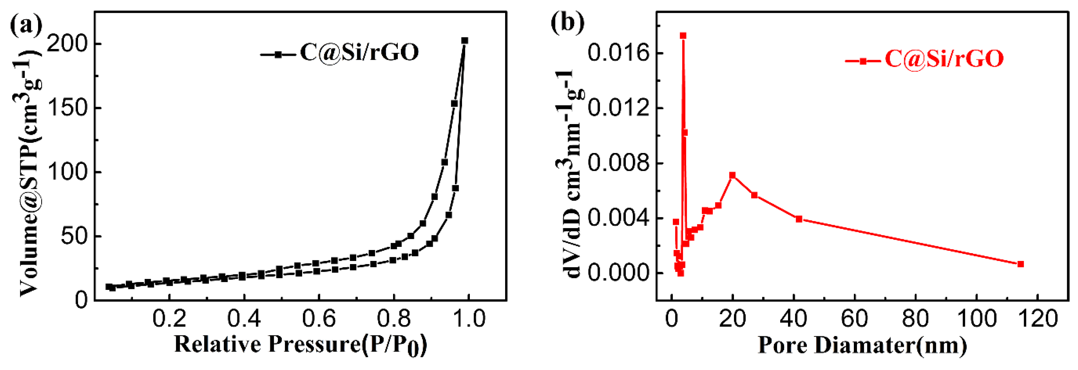
| Material | SBET [a] [m2 g−1] | Smeso [b] [m2 g−1] | Vtotal [c] [cm3 g−1] | Vmeso [d] [cm3 g−1] | APD [e] |
|---|---|---|---|---|---|
| C@Si/rGO | 50.0 | 63.3 | 0.313 | 0.315 | 25.10 |
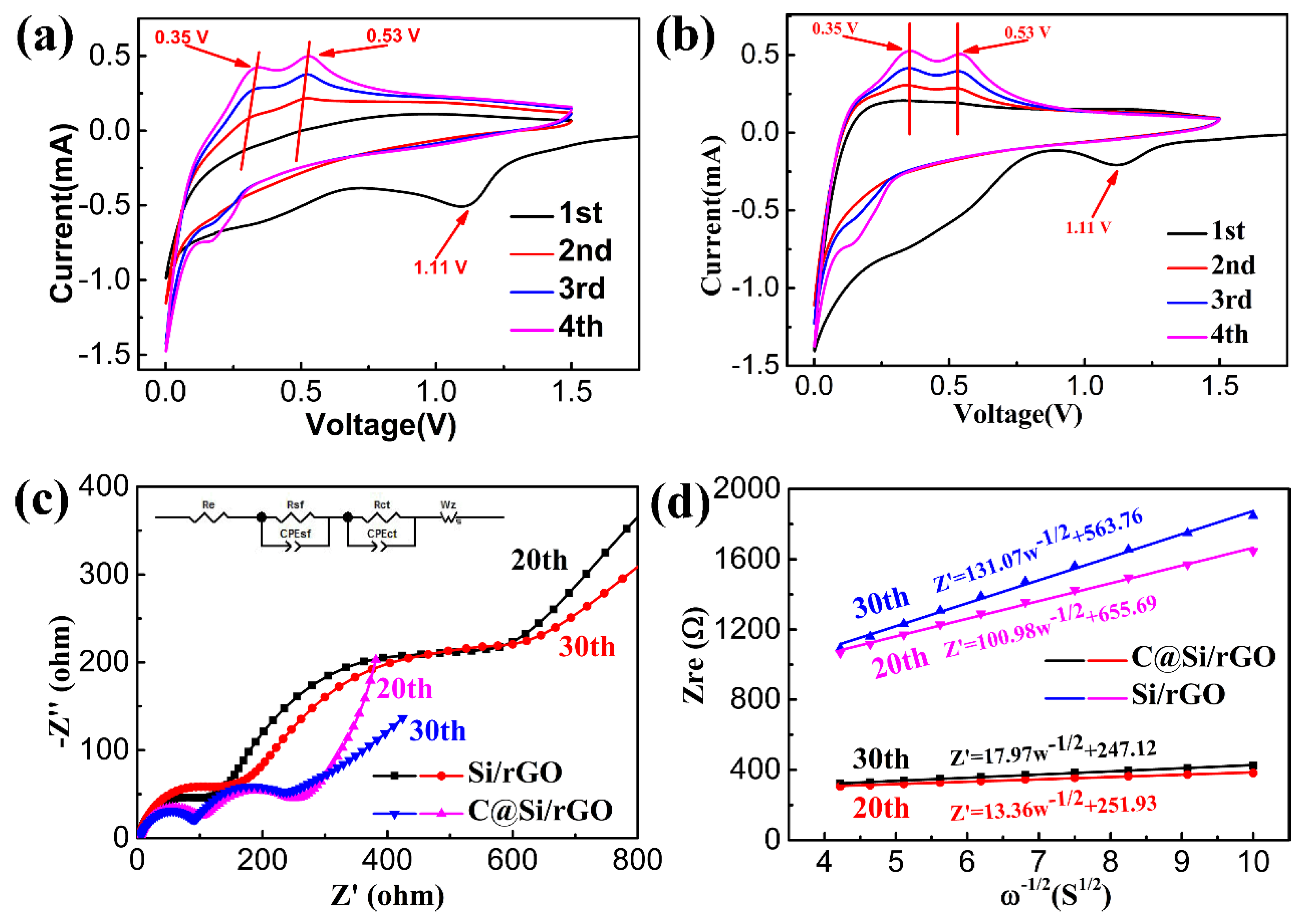
| Sample | Re (Ω) | Rsf (Ω) | Rct (Ω) | CPE1 (F) | CPE2 (F) | W (Ω·s−1/2) |
|---|---|---|---|---|---|---|
| Si/rGO | 2.37 | 92.0 | 310.6 | 5.34 × 10⁻⁶ | 2.52 × 10⁻⁴ | 0.42 |
| 2.61 | 116.9 | 508 | 5.82 × 10⁻⁶ | 4.10 × 10⁻⁴ | 0.44 | |
| C@Si/rGO | 4.95 | 81.0 | 113.1 | 1.33 × 10⁻⁵ | 6.93 × 10⁻⁴ | 0.36 |
| 4.29 | 93.6 | 160.2 | 1.65 × 10⁻⁵ | 7.26 × 10⁻⁴ | 0.60 |
| Samples | Potential Cut-Off (V) | Cycle Number | Initial Columbic Efficiency (CE) | Specific Discharge Capacity (mAh g−1) | Current Density (mAg−1) | Ref. |
|---|---|---|---|---|---|---|
| C@Si/rGO films | 0.01–1.5 | 100 | 61.82% | 1988 | 100 | This work |
| Si/rGO film | 0.01–3.0 | 150 | 53.00% | 2030 | 200 | [18] |
| Si/GP-2 | 0.02–2.0 | 100 | 61.40% | 2262 | 100 | [10] |
| Si/rGO film | 0.05–1.2 | 1300 | 54.00% | 2501 | 400 | [9] |
| I-rGO/Si | 0.00–1.5 | 100 | 75.90% | 2154 | 100 | [19] |
| Si-CNT/G paper | 0.005–1.5 | 100 | 58.00% | 2100 | 200 | [20] |
© 2019 by the authors. Licensee MDPI, Basel, Switzerland. This article is an open access article distributed under the terms and conditions of the Creative Commons Attribution (CC BY) license (http://creativecommons.org/licenses/by/4.0/).
Share and Cite
Li, X.; Bai, Y.; Wang, M.; Wang, G.; Ma, Y.; Huang, Y.; Zheng, J. Dual Carbonaceous Materials Synergetic Protection Silicon as a High-Performance Free-Standing Anode for Lithium-Ion Battery. Nanomaterials 2019, 9, 650. https://doi.org/10.3390/nano9040650
Li X, Bai Y, Wang M, Wang G, Ma Y, Huang Y, Zheng J. Dual Carbonaceous Materials Synergetic Protection Silicon as a High-Performance Free-Standing Anode for Lithium-Ion Battery. Nanomaterials. 2019; 9(4):650. https://doi.org/10.3390/nano9040650
Chicago/Turabian StyleLi, Xing, Yongshun Bai, Mingshan Wang, Guoliang Wang, Yan Ma, Yun Huang, and Jianming Zheng. 2019. "Dual Carbonaceous Materials Synergetic Protection Silicon as a High-Performance Free-Standing Anode for Lithium-Ion Battery" Nanomaterials 9, no. 4: 650. https://doi.org/10.3390/nano9040650
APA StyleLi, X., Bai, Y., Wang, M., Wang, G., Ma, Y., Huang, Y., & Zheng, J. (2019). Dual Carbonaceous Materials Synergetic Protection Silicon as a High-Performance Free-Standing Anode for Lithium-Ion Battery. Nanomaterials, 9(4), 650. https://doi.org/10.3390/nano9040650