Abstract
Controlling the distribution of the Mn12–stearate, single-molecule magnets (SMMs) anchored on a select surface is expected to be a new method for tuning its interactions, and an investigation on the magnetic properties of separated magnetic molecules is also lacking. The anchoring of the SMMs at the surface with an assumed statistic distance between each other is not an easy task; nevertheless, in this work, we show a synthesis which allows for this in detail. The immobilization of the Mn12–stearate was demonstrated with the use of FTO glasses and spherical silica as substrates. Based on differential pulse anodic stripping voltammetry (DPASV) and transmission electron microscopy (TEM) observations, we proved the efficiency of the method proposed. We observed continuous decreasing the number of bonds, and afterward, decreasing in the number of immobilized molecules with an increasing the number of spacer units used for separation of the magnetic particles.
The current developments in surface chemistry provide excellent opportunities for creating new materials and exploring novel and unique phenomena that take place on the surfaces of substances. In that vein, the functionalization of a surface plays an important role, and there are a great variety of techniques and methods aimed at modification of surfaces of nanoscale structures [1]. Surfaces of solids such as silica, glass, or carbon provide the opportunity to create unusual arrangements of atoms and molecules and also to connect materials with entirely different properties [2]. On the other hand, since every chemical modification changes the functionality of a surface, some significant effects, in contrast to “bulk” properties, should be taking into account [3].
For the organic functionalization of semiconductors silicon surfaces, self-assembled monolayers and direct attachment of oxygen- and carbon-free chemical functions [4] can be used. Additionally, introducing organic functional groups on silica surfaces is possible by the use of the immobilization of a monomeric [5] or polymeric [6] silane precursor. Also, a new class of materials, which is attractive from the functionalization point of view and characterized by large specific surface areas, is silica-based mesoporous materials. The incorporation of some functional units, in this case, can be achieved by applying grafting or co-condensation methods or using periodic mesoporous organosilicates [7]. Such a material has potential applications in the fields of catalysis and environmental remediation [8], or for use as a tunable, nonlinear optical material [9] for the performance of optoelectronic devices.
A glass surface can also be used as a substrate to produce functional materials. In this case, using zeolite microcrystals as model microbuilding blocks [10] opens up a possible application of zeolites as advanced materials. A more promising material for surface modification is Fluoride doped Tin Oxide (FTO) coated glass, which shows efficient surface chemical functionalization through electrochemical grafting [11] or by electrostatic self-assembled monolayers of transition metal cations receptors [12].
However, an essential issue of surface functionalization, which was not included in aforementioned techniques, is the possibility to separate the individual functionalities and to control not only distances between them but their interactions. Such a solution is possible to realize using spacer units [13], which gives the possibility of horizontal distributions of the functional groups. Such an approach is a critical factor of intermolecular interaction controlling and opens up extensive opportunities for practical applications. An interesting and promising option is deposition on the surface of magnetic molecules [14]. As it was shown in [15], attaching Mn12–stearate single-molecule magnets (SMMs) to the surface of spherical silica, allows one to separate the individual molecular magnets.
Here we present a procedure that provides a possibility of controlling statistic distance between SMMs on a surface by using spacer units. Theoretically, it is possible not only to separate the SMMs but also to tune mean intermolecular distances between SMMs by adjusting the number of spacer molecules: more separator molecules with regard to anchoring units, means a larger distance between anchored functionalities. In this study, we experimentally demonstrate this idea for the case of SMMs. We propose anchoring the Mn12–stearate single-molecule magnets onto a surface of two types of substrates. The first one is FTO covered glass. The conductive substrate allows for the investigation of the samples utilizing electrochemistry methods. The second one is spherical nanosilica, allowing for the direct observation the Mn12-stearate SMMs [15]. As the anchoring units we applied propyl carbonic acid groups, while the role of spacers was played by trimethoxysilane. The schema of the material and illustration of proposed idea is shown in Figure 1.
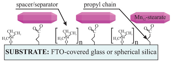
Figure 1.
Schema of the proposed material: Mn12–stearate single-molecule magnets distributed onto FTO glass or spherical silica nanoparticles with assumed distributions. The intervals between Mn12–stearate single-molecule magnets (SMMs) can be controlled by tuning the numbers of the spacer groups (n) with respect to the number of the Mn12–stearate-containing units.
The concept is a combination of those described earlier by our team [13,15]. After preliminary testing, the procedure worked predictably, according to our assumption, at first glance. After careful analysis and comparison of the results of electrochemical measurements and TEM observation, nevertheless, it turned out that the Mn12–stearate immobilization mechanism was more complicated than we assumed. The finding presented in this work seems to be very important for controlling the distribution of single-molecule magnets on the surface. The procedure allows for obtaining separated SMM on the surface and tuning the statistic intermolecular distances. The ability to attach isolated magnetic molecules on the surface will enable us to directly investigate their properties as single molecules in contrast to their study or extrapolation of their properties using a bulk analysis. The use of this approach opens a wide possibility for synthesis of materials that can be used in molecular-based magnetic devices (such as data storage and spintronics devices) and in quantum computation.
As mentioned before, we prepared samples in two forms: based on FTO-glass (1), and as a fine powder based on spherical silica (2). Both were prepared in an analogous way. The synthesis routes involve a few steps, as illustrated in Figure 2.
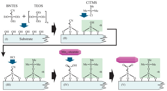
Figure 2.
Schema of the functionalization route allowing for the statistical control of the distances between anchored Mn12–stearate single-molecule magnets. Abbreviations: BNTES—butyronitrile triethoxysilane, TEOS—tetraethyl orthosilicate, ClTMS—Chlorotrimethylsilane, Me—methyl groups, Et—ethyl units.
Before the proper chemical processing, we prepared substrates: FTO glasses (3D Nano Ltd., Krakow, Poland) were degreased by the use of mechanical washing with a regular detergent. Next, the substrates were soaked in a solution containing a mixture of concentrated HCl (Poch Inc., Gliwice, Poland) and methanol (1:1 of the volume) for one hour. After this process, we washed the substrates with distilled water and dried them by flowing dry nitrogen. Spherical silica was synthesized as described in the literature [16], and used as prepared. Samples based FTO-glass were named FTO-COOMn12, while those based on spherical silica hereafter are called SILS-COOMn12. The synthesis of Mn12–stearate was performed according to the protocol described previously [17,18].
In Step I we grafted the substrates with the precursors of the anchoring units and spacer groups. To that end, the (Solution I) was prepared. It contained the mixture of butyronitrile triethoxysilane (BNTES—Sigma-Aldrich, Saint Louis, MI, USA) and tetraethyl orthosilicate (TEOS—Sigma-Aldrich Inc., Saint Louis, MI, USA) in toluene. The total concentration of TEOS and BNTES was 10−2 mol/dm3 for both substrates, while their molar proportion determined the distances between functional units: BNTES created the anchoring group for the functionality, while TEOS was a precursor of the spacer unit. We applied various proportions of BNTES and TEOS—1:0, 1:3, 1:6, 1:9, 1:12, and 1:15—which corresponded to the number of spacer units for each one anchoring molecule. In order to distinguish the samples, we added the number of spacers after the name; for example SILS-COOMn12N0 means spherical silica-based material does not contain any separators (N0—only BNTES), while sample SILS-COOMn12N15 includes 15 spacers per one anchoring unit (N15—initial proportion BNTES:TEOS, 1:15 molar ratio). Analogously, we had FTO-COOMn12N0 with no spacers and FTO-COOMn12N15 with 15 spacers.
For the case of FTO coated glass we immersed them into Solution I for 24 h. Subsequently, we washed the pre-functionalized glasses by immersing in the toluene ultrasonic bath for 1 hour in order to remove any excess of silane from the surface and to avoid the polymerization. Next, we rewashed the substrates and dried them. As a result, we obtained FTO glasses which contained cyanopropyl and hydroxyl units on the surfaced in concentrations depending on the initial molar proportions of BNTES and TEOS.
In the Step II we silylized our materials: hydroxyl units were converted into trimethyl silane groups (constituting spacers). To do this we treated samples with a solution of chlorotrimethylsilane (ClTMS) in toluene (2% of volume)—Solution II. Pre-functionalized FTO glasses were immersed in this solution and for 24 h at room temperature. After this process the samples were rinsed with toluene and acetone. After drying under vacuum for two hours samples were ready for further processing.
During the (Step III) the cyanopropyl units were transformed into propyl carbonic acid groups (constituting the anchors for Mn12-stearate molecules) by hydrolysis. To do this we soaked the samples in the concentrated hydrochloric acid (37%—Solution III) for at least 5 h. Next, we rinsed the samples several times with deionized water, and dried under vacuum for two hours.
In the last step, we functionalized the anchoring units (carbonic acid) by Mn12–stearate molecules (Step IV). To do this we immersed the substrates containing propyl carboxy units in the solution of Mn12–stearate in dichloromethane (0.1 g of Mn12–stearate in 50 mL of CH2Cl2—(Solution IV)). The procedure was carried out in a weighing dish and under ultrasonification for 20 h. After this we rinsed the samples by the solvent for a few times to remove residues of the doping agent, and dried them under vacuum for a few hours. The resulting material was meant to posses SMMs immobilized at the substrate’s surface via bounding by propyl carbonic acid anchoring units. Functionalized FTO glasses were stored in a refrigerator under an argon atmosphere.
Similar steps were applied for spherical silica. Firstly, the spherical silica was mixed with Solution I under reflux overnight (0.5 g of spherical silica per 50 mL of the solution I). Next, we recovered the product by centrifugation and washed it with pure toluene. We repeated this procedure four times, and subsequently dried the resulting powder under vacuum.
Next, the silylation was carried out by mixing the pre-functionalized powder with Solution II under reflux, similarly to what is described above.
Hydrolysis was carried out by concentrated hydrochloric acid. We performed the reaction under reflux (12 h). Subsequently, we centrifuged the resulting powder and washed it by water and acetone (four times, until neutral pH was reached).
Finally, we functionalized the silica containing carbonic acid anchoring units on the surface with Mn12–stearate. For the functionalization of 0.3 g of silica, we applied 50 mL of the Solution IV (for all concentrations of the anchoring units). We mixed this suspension overnight at room temperature under an argon protective atmosphere. The resulting powders (SILS-COOMn12NX, where X was a number of spacers per one anchoring unit) were recovered by centrifugation, washed by dichloromethane five times, and dried under vacuum for 10 h. Samples were stored in an argon atmosphere in a refrigerator.
We assumed that by the variation of the number of spacers, it would be possible to control the distribution of the anchored single-molecule magnets. To check our assumption, we decided to carry out two crucial investigations: differential pulse anodic stripping voltammetry (DPASV) for the case of samples prepared on FTO-glasses and TEM microscopy for spherical silica-based materials. The DPASV is a susceptible technique allowing for quantitative estimation of the number of the bonds between substrate and SMMs [19,20]. TEM microscopy (FEI Tecnai G2 20 X-TWIN with an LaB6 emission source and an FEI Eagle 2 K CCD camera - Thermo Fisher Scientific Inc., Waltham, MA, USA), in turn, allows for direct observation of the SMMs anchored at the surface of spherical silica, as we have shown before [15]. Measurements of the pristine substrates as a reference are covered in Supplementary Materials.
The DPASV spectra (SP200 potentiostat/galvanostat, BioLogic Inc., Seyssinet-Pariset, France) of the FTO-glass-based samples are shown in Figure 3. The spectra are quite noisy (normal taking into account that a relatively low amount of the detected specimen), but DPASV peaks are clearly visible. For all samples, we can see characteristic stripping asymmetric peaks at +0.28 V. This confirms the presence of the anchored molecules: Mn12 in this case.
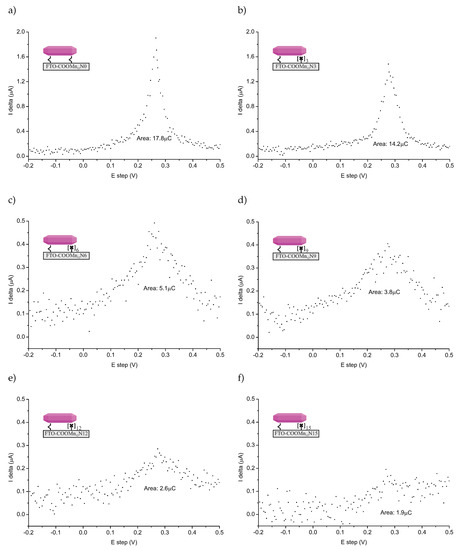
Figure 3.
Differential pulse anodic stripping voltammetry (DPASV) recorded for FTO covered glass functionalized by Mn12-stearate molecules anchored via propyl-carbonic groups distributed onto the surface with various densities: full functionalization (no spacers between functionalities—sample FTO-COOMn12 N0—(a)), three (FTO-COOMn12 N3—(b)), six (FTO-COOMn12g N6—(c)), nine (FTO-COOMn12g N9—(d)), 12 (FTO-COOMn12g N12—(e)), and 15 (FTO-COOMn12g N15—(f)) spacers between anchoring units. Note, that the Y axis scale is larger for the cases of (a) and (b).
The position of the DPASV peak suggested that we were dealing with chemically bonded specimens [19]. The relatively high value of the potential is typical for specimens bonded via covalent-polarized bonds of carbonic units [13,21], not only physically adsorbed ones. What is more, the peaks are well-localized. On this basis, we can conclude that a single type of ionization connected with charge transport, and, in our opinion, that was stripping bonds between carbonic groups and the SMMs. Another fact arguing for this, is that we did not adsorb any SMMs molecules at the supports not-containing anchoring units (see Supplementary Materials). Naturally, we need to take into account the possible decomposition of the Mn12–stearate molecules as well. In our opinion, however, this is unlikely, since in such a case, we would expect the peak or rather peaks’ positions to be different than what is typical for the stripping of carbonic bonds. Of course, we cannot exclude such a possibility.
The relative amounts of bounds can be estimated by measuring the area under the DPASV peaks [19] (see values given in Figure 3). The comparison of the relative amount of the bounds was according to our expectations at first glance. More spacer units caused less bonds between the surface and SMMs. We must emphasize nevertheless, that it does not mean less of the anchored magnetic molecules at all. To understand this, let us consider TEM microscopic images for the samples based on spherical silica with the concentration of the anchored single-molecule magnets corresponding to the materials based on FTO-glasses. The resulting images can be seen in Figure 4.
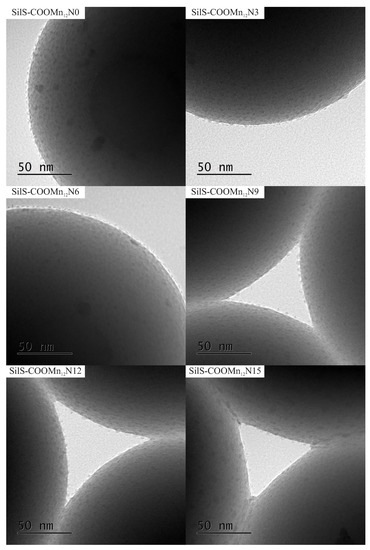
Figure 4.
The transmission electron microscopy images of the spherical silica-based materials containing individual Mn12–stearate molecules attached to the surface with various concentration of the anchoring units.
The TEM results are quite surprising. For all cases, one can see separate Mn12–stearate molecules at the surface. Nevertheless, we can clearly observe, that for the samples SILS-COOMn12N0, SILSCOOMn12N3, and SILS-COOMn12N6 SMMs are very densely distributed on the surface—molecule by molecule. No difference in distribution can be distinguished. In our previous work, we maintained that Mn12–stearate molecules were bonded at the surface in an umbrella-like configuration [15]. That is visible for the samples SILS-COOMn12N0 and SILS-COOMn12N3. Closer inspection of the TEM image of SILS-COOMn12N6 sample reveals one important detail, however. This sample shows Mn12–stearate molecules that are bounded in different orientations like those marked in the Figure 5.
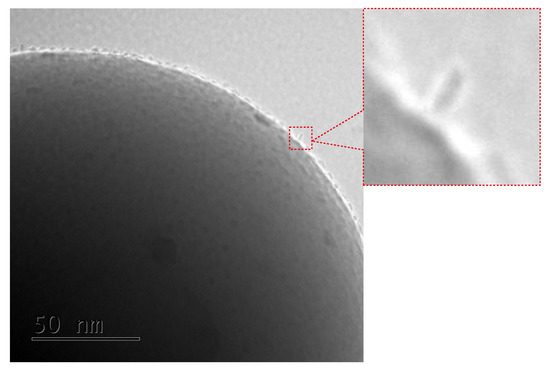
Figure 5.
Closer inspection of the TEM image of the SILS-COOMn12N6 sample: enlarged part of the microphotograp shows the Mn12–stearate molecules attached in different configurations than the umbrella-like.
This orientation of the SMMs can be observed for the samples SILS-COOMn12N9, SILS-COOMn12N12, and SILS-COOMn12N15 as well. Moreover, for these samples, we can clearly see a decrease in the number of anchored Mn12–stearate molecules. Why then can we observe a reduction in the anchored SMMs’ density after applying at least six spacers per anchoring unit? This finding seems to be inconsistent with the DPASV results. The explanation can be found by analyzing the molecular structure of the Mn12 molecule [22]. It has the form of a flattened ellipsoid with organic ligands located four each flat side and eight on the circumference of the molecule (a total of sixteen). The umbrella-like arrangement involves, probably, two to four bonds. In such a configuration the molecule is rigidly attached to the surface. When only one anchor is involved for immobilization of the SMMs, the molecule is relatively free, and arrangements different than umbrella-like are also possible. Looking at the TEM results we can say that the concentration of the spacer units of six per single anchoring group involves the single bond of the Mn12–stearate to the surface. Concentrations of the spacers of below this value do not cause an increase in the number of anchored SMMs but an increase the number of bonds between Mn12 and the support. This conclusion is in agreement with DPASV results: when the molecule is anchored via four bonds, its detection involves the exchange of four electrons and only one for a single bond. Thus, we observe continuous diminishing in the area under the DPASV, while TEM imaging shows roughly the same number of immobilized magnetic molecules, up to the six spacers per anchoring unit.
Here we must remark that some other research was carried out to check the chemical compositions of our specimens: energy-dispersive X-ray spectroscopy (EDX – FEI Tecnai G2 20 X-TWIN with an LaB6 emission source and an FEI Eagle 2 K CCD camera and X-Ray microanalyzer EDX—Thermo Fisher Scientific Inc., Waltham, MA, USA), Raman spectroscopy (confocal Raman microscope CRM alpha 300, WITec Inc., Ulm, Germany), and SQUID magnetometry (MPMS magnetometer, Quantum Design Inc., San Diego, CA, USA). Due to the reason of very low concentrations of the functional groups, EDX and Raman did not bring unambiguous results. The SQUID magnetometry proved that the Mn12–stearate molecules did not lose their SMMs properties. Moreover, SQUID research revealed extremely interesting behaviors of the material (a quantum tunneling phenomenon, non-linear dependence of the coercive field on the Mn12 concentration, and many more). The description of the magnetic properties of the materials is very extensive and is presented in a pending article. Magnetic research did not prove the light shed on the connection between Mn12–stearate and silica support though. For this reason, the only information about the chemical bonding between SMMs and the substrate was provided by DPASV.
Summing up both TEM and DPASV research, we observed that with the increase in the number of spacer units up to six per single anchoring molecule, we dealt with a decreasing of bonds between the support and Mn12–stearate, not diminishing the number of immobilized SMMs though. The reducing number of anchored magnetic molecules can be observed when the number of spacers is more than six per one anchoring molecule. Moreover, we can say that the samples SILS-COOMn12N6 or FTO-COOMn12N6 are optimal: they possess the largest possible numbers of immobilized SMMs with the smallest possible numbers of bonds. For the case of immobilization with Mn12 with more than a single anchoring point, the molecule is relatively rigid. Its mobility is limited. Therefore, the samples with six spacers contained the highest possible concentration of non-rigid, single-molecule magnets. This fact is reflected in the magnetic properties of such materials (work in preparation).
Supplementary Materials
The following are available online at https://www.mdpi.com/2079-4991/9/12/1730/s1, Figure S1: The experiment verifying the role of anchoring units—the case of spherical silica: the transmission electron microscopy images of the materials at different stages of the synthesis and with the application of various steps of the procedure. Pure spherical silica (a), pure spherical silica functionalized by Mn12–stearate (b), silica with carbonic acid units and spacers in proportion 1:3 (c), silica with carbonic acid units and separators in ratio 1:3 functionalized by Mn12-st (d). Figure S2: The experiment verifying the role of anchoring units—the case of FTO-glasses: the DPASV results for the materials at different stages of the synthesis and with the application of various steps of the procedure. Pure spherical silica (a), pure spherical silica functionalized by Mn12–stearate (b), silica with carbonic acid units and spacers in proportion 1:3 (c), silica with carbonic acid units and separators in ratio 1:3 functionalized by Mn12–stearate (d). Figure S3: The DPASV results for of the spherical silica-based materials containing individual Mn12–stearate molecules attached to the surface with various concentration of the anchoring units (N means number of the spacer with regards to single anchoring group), juxtaposed with a pure FTO-glasse (FTO-pure), and FTO-glass functionalized by Mn12-stearate molecules (with no use of anchoring units). Figure S4: The transmission electron microscopy images of the spherical silica-based materials containing individual Mn12–stearate molecules attached to the surface with various concentration of the anchoring units (N means number of the spacer with regards to single anchoring group), juxtaposed with a pure spherical silica (SilS-pure), and pristine silica functionalized by Mn12–stearate molecules (with no use of anchoring units—SilS-Mn12).
Author Contributions
Conceptualization, M.L., O.P. and Ł.L.; methodology, M.L. and Ł.L.; validation, Ł.L., M.L., D.K. and O.P.; formal analysis, O.P. and M.L.; investigation, Ł.L., M.L., D.K. and O.P.; resources, M.L. and O.P.; writing—original draft preparation, O.P., Ł.L. and M.L.; writing—review and editing, M.L. and Ł.L.; visualization, M.L.; supervision, M.L.; project administration, Ł.L.; funding acquisition, Ł.L. All authors contributed to the discussion of the results and analyzed the data.
Funding
This work has been supported by the resources of the National Science Center (grant number: 2017/26/E/ST5/00162).
Acknowledgments
The authors are grateful to Maciej Zubko for performing TEM microscopy.
Conflicts of Interest
The authors declare no conflict of interest.
Abbreviations
The following abbreviations are used in this manuscript:
| FTO | Fluoride doped Tin Oxide |
| Mn12ac16 | [Mn12O12(CH3(CH2)16CO2)11(CH3CO2)5(H2O)4]·2CH3COOH |
| Mn12–stearate | derivative of Mn12 containing strearic acid ligands |
References
- Zhang, Y.; Kohler, N.; Zhang, M. Surface modification of superparamagnetic magnetite nanoparticles and their intracellular uptake. Biomaterials 2002, 23, 1553–1561. [Google Scholar] [CrossRef]
- Rahman, I.A.; Padavettan, V. Synthesis of silica nanoparticles by sol-gel: Size-dependent properties, surface modification, and applications in silica-polymer nanocomposites—A review. J. Nanomater. 2012, 2012, 8. [Google Scholar] [CrossRef]
- Bagwe, R.P.; Hilliard, L.R.; Tan, W. Surface modification of silica nanoparticles to reduce aggregation and nonspecific binding. Langmuir 2006, 22, 4357–4362. [Google Scholar] [CrossRef] [PubMed]
- Gao, F.; Teplyakov, A.V. Challenges and opportunities in chemical functionalization of semiconductor surfaces. Appl. Surf. Sci. 2017, 399, 375–386. [Google Scholar] [CrossRef]
- Park, J.W.; Jun, C.H. Transition-metal-catalyzed immobilization of organic functional groups onto solid supports through vinylsilane coupling reactions. J. Am. Chem. Soc. 2010, 132, 7268–7269. [Google Scholar] [CrossRef] [PubMed]
- Park, J.W.; Kim, D.S.; Kim, M.S.; Choi, J.H.; Jun, C.H. A method for introducing organic functional groups on silica surfaces using a functionalized vinylsilane containing polymer. Polym. Chem. 2015, 6, 555–560. [Google Scholar] [CrossRef]
- Hoffmann, F.; Cornelius, M.; Morell, J.; Fröba, M. Silica-based mesoporous organic–inorganic hybrid materials. Angew. Chem. Int. Ed. 2006, 45, 3216–3251. [Google Scholar] [CrossRef]
- Sayari, A.; Hamoudi, S. Periodic mesoporous silica-based organic- inorganic nanocomposite materials. Chem. Mater. 2001, 13, 3151–3168. [Google Scholar] [CrossRef]
- Laskowska, M.; Kityk, I.; Dulski, M.; Jędryka, J.; Wojciechowski, A.; Jelonkiewicz, J.; Wojtyniak, M.; Laskowski, Ł. Functionalized mesoporous silica thin films as a tunable nonlinear optical material. Nanoscale 2017, 9, 12110–12123. [Google Scholar] [CrossRef]
- Yoon, K.B. Organization of zeolite microcrystals for production of functional materials. Accounts Chem. Res. 2007, 40, 29–40. [Google Scholar] [CrossRef]
- Lamberti, F.; Agnoli, S.; Brigo, L.; Granozzi, G.; Giomo, M.; Elvassore, N. Surface functionalization of fluorine-doped tin oxide samples through electrochemical grafting. ACS Appl. Mater. Interfaces 2013, 5, 12887–12894. [Google Scholar] [CrossRef] [PubMed]
- Jasiecki, S.; Czupryniak, J.; Ossowski, T.; Schroeder, G. FTO coated glass electrode functionalization with transition metal cations receptors via electrostatic self-assembly. Int. J. Electrochem. Sci. 2013, 8, 12543–12556. [Google Scholar]
- Laskowska, M.; Oyama, M.; Kityk, I.; Marszalek, M.; Dulski, M.; Laskowski, L. Surface functionalization by silver-containing molecules with controlled distribution of functionalities. Appl. Surf. Sci. 2019, 481, 433–436. [Google Scholar] [CrossRef]
- Mannini, M.; Pineider, F.; Sainctavit, P.; Danieli, C.; Otero, E.; Sciancalepore, C.; Talarico, A.M.; Arrio, M.A.; Cornia, A.; Gatteschi, D.; et al. Magnetic memory of a single-molecule quantum magnet wired to a gold surface. Nat. Mater. 2009, 8, 194. [Google Scholar] [CrossRef] [PubMed]
- Laskowski, L.; Kityk, I.; Konieczny, P.; Pastukh, O.; Schabikowski, M.; Laskowska, M. The Separation of the Mn12 Single-Molecule Magnets onto Spherical Silica Nanoparticles. Nanomaterials 2019, 9, 764. [Google Scholar] [CrossRef]
- Stöber, W.; Fink, A.; Bohn, E. Controlled growth of monodisperse silica spheres in the micron size range. J. Colloid Interface Sci. 1968, 26, 62–69. [Google Scholar] [CrossRef]
- Park, C.D.; Jeong, D.Y. Soluble Single-Molecule Magnet: Mn12-stearate. Bull. Korean Chem. Soc. 2001, 22, 611–615. [Google Scholar]
- Verma, S.; Verma, A.; Srivastava, A.K.; Gupta, A.; Singh, S.P.; Singh, P. Structural and magnetic properties of Mn12-Stearate nanomagnets. Mater. Chem. Phys. 2016, 177, 140–146. [Google Scholar] [CrossRef]
- Etienne, M.; Bessiere, J.; Walcarius, A. Voltammetric detection of copper (II) at a carbon paste electrode containing an organically modified silica. Sens. Actuators B Chem. 2001, 76, 531–538. [Google Scholar] [CrossRef]
- Laborda, E.; González, J.; Molina, Á. Recent advances on the theory of pulse techniques: A mini review. Electrochem. Commun. 2014, 43, 25–30. [Google Scholar] [CrossRef]
- Laskowski, Ł.; Laskowska, M.; Dulski, M.; Zubko, M.; Jelonkiewicz, J.; Perzanowski, M.; Vila, N.; Walcarius, A. Multi-step functionalization procedure for fabrication of vertically aligned mesoporous silica thin films with metal-containing molecules localized at the pores bottom. Microporous Mesoporous Mater. 2019, 274, 356–362. [Google Scholar] [CrossRef]
- Lis, T. Preparation, structure, and magnetic properties of a dodecanuclear mixed-valence manganese carboxylate. Acta Crystallogr. Sect. B Struct. Crystallogr. Cryst. Chem. 1980, 36, 2042–2046. [Google Scholar] [CrossRef]


© 2019 by the authors. Licensee MDPI, Basel, Switzerland. This article is an open access article distributed under the terms and conditions of the Creative Commons Attribution (CC BY) license (http://creativecommons.org/licenses/by/4.0/).