Article

Electrochemical Analysis for Demonstrating CO Tolerance of Catalysts in Polymer Electrolyte Membrane Fuel Cells

Graduate School of Energy Science and Technology (GEST), Chungnam National University, 99 Daehak-ro, Yuseong-gu, Daejeon, 34134, Korea
*
Author to whom correspondence should be addressed.
These authors contributed equally to this work.
Nanomaterials 2019, 9(10), 1425; https://doi.org/10.3390/nano9101425
Submission received: 11 September 2019 / Revised: 29 September 2019 / Accepted: 1 October 2019 / Published: 8 October 2019

Abstract

:
Since trace amounts of CO in H2 gas produced by steam reforming of methane causes severe poisoning of Pt-based catalysts in polymer electrolyte membrane fuel cells (PEMFCs), research has been mainly devoted to exploring CO-tolerant catalysts. To test the electrochemical property of CO-tolerant catalysts, chronoamperometry is widely used under a CO/H2 mixture gas atmosphere as an essential method. However, in most cases of catalysts with high CO tolerance, the conventional chronoamperometry has difficulty in showing the apparent performance difference. In this study, we propose a facile and precise test protocol to evaluate the CO tolerance via a combination of short-term chronoamperometry and a hydrogen oxidation reaction (HOR) test. The degree of CO poisoning is systematically controlled by changing the CO adsorption time. The HOR polarization curve is then measured and compared with that measured without CO adsorption. When the electrochemical properties of PtRu alloy catalysts with different atomic ratios of Pt to Ru are investigated, contrary to conventional chronoamperometry, these catalysts exhibit significant differences in their CO tolerance at certain CO adsorption times. The present work will facilitate the development of catalysts with extremely high CO tolerance and provide insights into the improvement of electrochemical methods.

Graphical Abstract

1. Introduction

Polymer electrolyte membrane fuel cells (PEMFCs) that use hydrogen (H2) as a fuel have attracted increasing research attention as the most promising next-generation power sources because of an eco-friendly reaction mechanism and high power density [1,2,3]. Conventionally, H2 is produced by steam reforming of methane gas, and the produced H2 gas contains trace amounts of carbon monoxide (CO) of 10–100 ppm [4,5]. However, this small amount of carbon monoxide is sufficient to cause detrimental effects on Pt catalysts widely used in PEMFCs, causing a tremendous suppression in their catalytic performance [6,7]. To alleviate the effect of CO poisoning, various strategies have been adopted, including alloying of Pt with other transition metals, such as Ru, Fe, and Co, formation of core-shell structures, and modification of support materials [8,9,10,11]. Among these strategies, the alloying of Pt with transition metals has been regarded as an efficient way to enhance the CO tolerance of Pt-based catalysts. Especially, PtRu catalysts have exhibited interesting electrochemical properties towards various anodic reactions, such as methanol and CO oxidation reactions, due to bi-functional and ligand effects, resulting in even higher CO tolerance in the hydrogen oxidation reaction (HOR) using reformed H2 gas [12,13,14,15,16].
In general, the CO tolerance for the HOR catalysts is evaluated using a CO/H2 mixture gas (CO concentrations are 10–100 ppm) as a fuel in a half-cell. In addition, the most commonly used electrochemical method is chronoamperometry, by which the change in currents can be observed as a function of time at a constant potential [17,18]. The chronoamperometry test has the advantage of observing the change in the HOR current at room temperature since only small amounts of catalysts are evaluated on a glassy carbon electrode. However, conventional chronoamperometry has difficultly in distinguishing the superiority of catalysts with relatively high CO tolerance, despite the physical characteristics (surface structure and composition) of the catalysts being different [19,20,21,22,23,24]. For instance, if a novel catalyst with a much higher CO tolerance is designed and surpasses the CO tolerance of the PtRu catalyst, the chronoamperometry technique cannot be a useful method in identifying the novelty of the developed catalysts since the performance difference is not very divergent in the chronoamperogram [24]. Therefore, to supplement the chronoamperometry results, researchers usually conduct additional characterization, such as CO stripping and methanol oxidation reaction (MOR) tests. Otherwise, one must simultaneously increase the CO concentration (200~500 ppm) in the CO/H2 mixture gas and the reaction temperature (40~60 °C) for the chronoamperometry test. Alternatively, after fabricating a membrane electrode assembly (MEA) for a unit cell test, its current–voltage (I–V) curve can be measured using the CO/H2 mixture gas as fuel. However, in this case, it takes a long time to make the MEA, and a skillful MEA fabrication technique is additionally required. Furthermore, if the concentration of carbon monoxide is too small (e.g., 10–100 ppm), the performance difference remains negligible since much larger amounts of catalysts are used in the MEA compared to the catalyst loading on the glassy carbon for the half-cell test. Therefore, there is a need to develop a unique and simple catalyst evaluation technique that can demonstrate distinguishable CO tolerance and clearly identify the superiority among the catalysts with much higher CO tolerance even at room temperature using a half-cell test with few experimental variables.
In this work, we propose a facile and reliable test protocol to evaluate the CO poisoning via a combination of short-term chronoamperometry and a simple HOR test. After pre-adsorption of CO on catalysts at a certain time during the short-term chronoamperometry, the HOR polarization curve was simply measured at room temperature and compared with that measured without CO adsorption to corroborate the CO tolerance. To confirm the applicable feasibility of the protocol, the electrochemical properties of PtRu alloy (Pt1Ru1 and Pt1Ru3) catalysts with different atomic ratios of Pt to Ru were mainly investigated. Through the modified tests, the significant difference in their CO tolerance was revealed, while there was no performance difference between them in the conventional chronoamperometry tests. Therefore, we believe that this protocol can clearly identify the CO tolerance difference by controlling the adsorption time using a high concentration of CO and effectively monitoring the HOR activity of the catalysts.

2. Materials and Methods

2.1. Materials

All chemical reagents used were of analytical grade and used without further purification. Carbon blacks (Vulcan XC72, Cabot) were purchased from Cabot Inc., Alpharetta, GA, USA. Commercialized Pt1Ru1/C and Pt/C catalysts (Johnson Matthey) were used as controls. Also, 1-Octadecene (90%), platinum acetylacetonate (Pt(acac)2, 97%), ruthenium acetylacetonate (Ru(acac)2, 97%), oleylamine (70%), Nafion ionomer (5 wt %), and 2-propanol (99.5%) were procured from Sigma-Aldrich Inc., USA. n-Hexane (95%) and ethanol (95%) were acquired from Samchun Pure Chemical, Daejeon, Korea.

2.2. Synthesis of Pt1Ru3/C catalyst

Carbon black (0.1 g) and 3.5 mL of oleylamine were well dispersed through ultrasonication in 147 mL of 1-octadecene for 20 min. Meanwhile, 0.034 g of Pt(acac)2, 0.035 g of Ru(acac)2, 3.5 mL of oleylamine, and 13 mL of 1-octadecene were taken in a separate vial and allowed to disperse through ultrasonication for 20 min. Afterwards, the two solutions were mixed well and further sonicated for 5 min and subjected to heating at 120 °C for 1 h under an Ar atmosphere to remove H2O impurities. After 1 h, the solution temperature was gradually raised to 300 °C and maintained for 2 h. After the thermal decomposition reaction of Pt and Ru precursors, the solution was cooled down to 80 °C. The catalyst-containing solution was filtered and then washed with a copious amount of n-hexane and ethanol solution. After the obtained product was dried in a vacuum oven at 60 °C, it was annealed at 600 °C for 2 h in 5% H2-mixed N2 gas and formulated as a Pt1Ru3/C catalyst.

2.3. Characterizations

The microstructure and morphologies of the catalysts, Pt1Ru1/C and Pt1Ru3/C, were observed using a high-resolution transmission electron microscopy (HRTEM, Tecnai G2 F30 S-Twin, FEI Thermo Fisher Scientific, Eindhoven, Netherlands). The atomic composition of the Pt1Ru3/C catalyst was confirmed by energy-dispersive X-ray spectroscopy (EDX, Tecnai G2 F30 S-Twin, FEI Thermo Fisher Scientific, Eindhoven, Netherlands) analysis using the TEM as shown in Figure S1. All electrochemical measurements were tested in a standard three-electrode system using a rotating disk electrode (RDE, Metrohm, Switzerland) with a glassy carbon (GC, Metrohm, Switzerland), Pt wire, and Ag/AgCl electrode as the working, counter, and reference electrodes, respectively. All potential values were represented versus the reversible hydrogen electrode (RHE). The RHE calibration was performed in an electrolyte solution by measuring the current using a Pt disk electrode between the potential ranges of hydrogen oxidation and evolution reactions. The catalyst ink was prepared by dispersing a mixture containing 5 mg of the prepared catalyst, Nafion ionomer (68.7 µL), and 2-propanol (500 µL) through ultrasonication for few minutes. A drop of catalyst ink (total metal loading = 44.86 μg cm−2) was applied to a glassy carbon electrode (0.196 cm2 geometric surface area) and then dried at room temperature. Cyclic voltammograms (CVs) were measured by cycling the potential between 0.05 and 1.05 VRHE at a scan rate of 20 mV s−1 in an Ar-saturated 0.1 M HClO4 electrolyte solution. For HOR tests, the potential was applied from −0.05 to 0.1 VRHE at a scan rate of 1 mV s−1 under a constant rotation speed of 1600 rpm in H2-saturated 0.1 M HClO4 solution. For CO stripping measurements, the working electrode potential was held at 0.05 VRHE for 15 min while bubbling pure CO gas into 0.1 M HClO4. After purging the electrolyte with Ar gas for 20 min, the residual CO molecules in the electrolyte were completely removed, and then, in Ar-saturated electrolyte, a CV was obtained at a scan rate of 20 mV s−1 within the potential range of 0.05 and 1.05 VRHE. The electrochemically active surface area (ECSA) was calculated by integrating the current in the CO oxidation peak region assuming a monolayer adsorption of CO molecules. For all chronoamperometry tests, the potential was maintained at 0.05 VRHE for 7200 s at 1600 rpm in H2- and 100 ppm CO-mixed H2-saturated 0.1 M HClO4. For the proposed new CO tolerance test, conventional chronoamperometry was modified by systematically controlling the gas atmosphere. First, the conventional chronoamperometry was performed for ~60 s in the same condition (at 0.05 VRHE with a rotation speed of 1600 rpm) using H2-saturated 0.1 M HClO4. After ~60 s, the gas atmosphere was immediately changed from H2 to CO while maintaining the applied potential (0.05 VRHE). In this step, pure CO gas was bubbled into 0.1 M HClO4 for a period of time (∆tCO = 0, 5, 15, or 30 s) for partial adsorption of CO molecules on the catalyst surface, followed by purging H2 gas for 20 min. Finally, the HOR polarization curve was measured in H2-saturated 0.1 M HClO4 at a scan rate of 1 mV s-1 within the potential range of −0.05 to 0.1 VRHE under a constant rotation speed of 1600 rpm.

3. Results and Discussion

The main purpose of this work is to provide clear insights into the facile and precise evaluation of CO tolerance for catalysts with different electrochemical properties. Therefore, to emphasize the applicable feasibility of the test protocol for CO tolerance measurement, we compared the electrochemical properties of two representative carbon-supported PtRu (Pt1Ru1/C and Pt1Ru3/C) alloy catalysts composed of different atomic ratios of Pt to Ru. First of all, the Pt1Ru3/C catalyst was prepared by a solution-based thermal decomposition reaction (the detailed synthesis procedure was described in the Section 2), and its CO tolerance was then compared with that of commercialized Pt1Ru1/C and Pt/C catalysts as controls.
It is well known that alloying Ru with Pt enhances the CO tolerance of the active Pt surface for the HOR by decreasing the CO binding energy [13]. For the Pt1Ru1/C catalyst, it is widely reported that the equivalent content of Pt and Ru (Pt/Ru = 1:1) is an ideal atomic ratio to have appropriately low CO binding energy and the number of active Pt sites can be ensured [25]. On the other hand, in the case of the Pt1Ru3/C catalyst, slightly lower CO tolerance is expected, since increasing the ratio of Pt to Ru above 1 causes an increase in CO binding energy of PtRu alloys [25,26].
As shown in Figure 1a,b, TEM images of Pt1Ru1/C and Pt1Ru3/C clearly show the uniform distribution of PtRu alloy nanoparticles with a particle size of 2 to 3 nm on carbon supports. To further understand the difference in the surface properties of Pt1Ru1/C and Pt1Ru3/C catalysts, CO stripping tests were performed for each sample, as shown in Figure 1c. The ECSA of a sample is obtained by integrating CO oxidation currents, and the information about its electrochemical property can be qualitatively estimated from the onset and peak potentials for the CO oxidation. As expected, the onset and peak potentials (0.45 and 0.57 VRHE, respectively) for the CO oxidation of Pt1Ru1/C were much lower than those (0.57 and 0.66 VRHE, respectively) of Pt1Ru3/C, indicating higher CO oxidation activity than Pt1Ru3/C [26]. However, it was clearly confirmed that the two PtRu/C catalysts still exhibit much higher CO oxidation activities due to the presence of surface Ru atoms compared to a bare Pt/C catalyst [27]. This result corresponded to that of previous reports showing that the change in the CO binding energy depends on the Ru content in PtRu alloys [13].
However, the CO stripping (or CO oxidation) test results, which were obtained by a potential scan between 0.05 and 1.05 VRHE, cannot directly represent the CO tolerance characteristic of the samples in the HOR since the anode overpotential is practically limited within 0.2 VRHE in PEMFCs [28,29]. Meanwhile, as shown in Figure 1d, Pt1Ru1/C and Pt1Ru3/C had similar particle diameters (estimated from the TEM images in Figure 1a,b) and ECSA values (calculated from the CO stripping curves shown in Figure 1c). From the above results, it might be concluded that Pt1Ru1/C and Pt1Ru3/C catalysts have a similar particle size and surface area while they have different CO binding energies due to different Ru content.
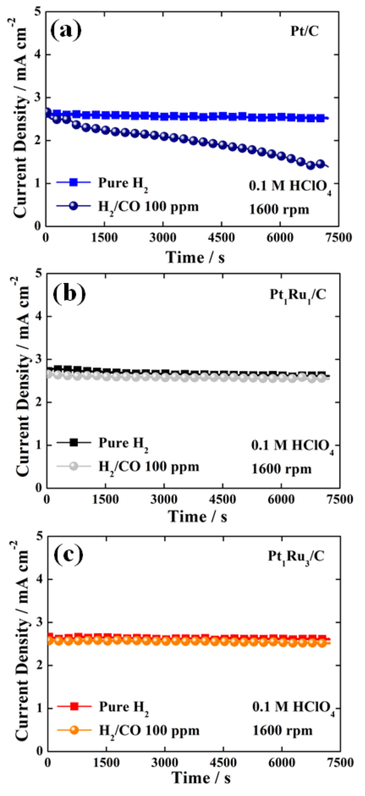
To investigate the CO tolerance of the catalysts, a chronoamperometry test, one of the most commonly used evaluation techniques, was conducted. Definitely, a Pt/C catalyst without Ru indicated much lower CO tolerance in the chronoamperometry tests, changing the gas atmosphere from pure H2 to 100 ppm CO-mixed H2 gases, as shown in Figure 2a. In sharp contrast, it was difficult to determine which of the Pt1Ru1/C and Pt1Ru3/C catalysts had better CO tolerance in the same test condition. As shown in Figure 2b and c, in pure H2 and 100 ppm CO-mixed H2 gas atmospheres, both Pt1Ru1/C and Pt1Ru3/C catalysts exhibited similarly high CO tolerance characteristics although they showed different CO oxidation activity in the CO stripping tests, as shown in Figure 1c. Hence, it is reasonable to assume that the above conventional chronoamperometry is not sensitive enough to judge the superiority between PtRu-based catalysts having a much lower CO binding energy and sufficiently high CO tolerance.
Alternatively, the test might be carried out using CO/H2 mixture gases containing more CO than 100 ppm to monitor the performance differences [30]. However, if CO/H2 mixture gases with a much higher CO concentration are used for the test at room temperature, it might be difficult to obtain normal HOR currents even for PtRu catalysts since the amount of CO adsorption on the Pt surface is considerably increased. Therefore, simply increasing the CO concentration in CO/H2 mixture gas is not helpful to clearly confirm the difference in the CO tolerance of catalysts at room temperature in half-cell tests using a very small catalyst loading on a glassy carbon electrode. To minimize the effect of temperature on the evaluation quality, in most cases, CO tolerance tests using CO/H2 mixture gases with a high CO concentration have been performed in unit cells operating at high temperature (60–85 °C) [31]. However, in this case, one has to fabricate an MEA and conduct the activation process of the MEA for a long time before the CO tolerance test. Therefore, it is crucial to develop a facile and reliable evaluation protocol that provides accurate and significant differences in CO tolerance testing even at room temperature in a half-cell.
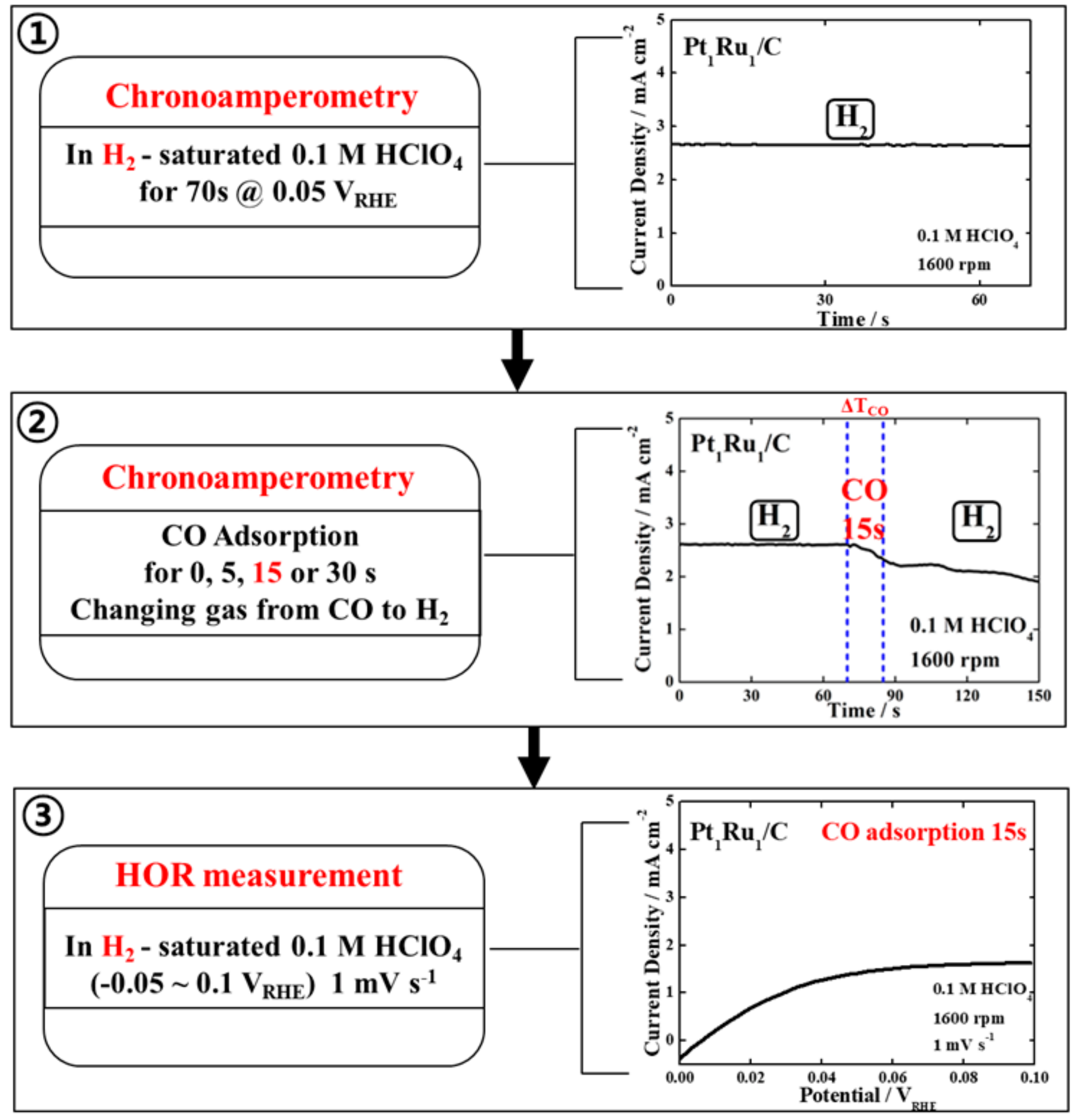
As shown in Figure 3, we designed a facile test protocol that combines short-term chronoamperometry and a simple HOR test at room temperature as an alternative approach. The proposed test protocol entails the following order of analysis. Step (1)—after purging the electrolyte with H2 gas for 20 min, measure chronoamperometry at a constant potential of 0.05 VRHE for ~60 s in H2-saturated electrolyte to confirm the HOR current of a sample under normal operating conditions, as shown in Figure S2a. Step (2)—change the bubbling gas from H2 to 100% CO gas to poison the catalyst surface with CO molecules for a desired time, e.g., 15 s, while simultaneously monitoring the changes in the chronoamperogram, as shown in Figure S2b–d. After the CO poisoning time, change the bubbling gas back to pure H2 gas. Step (3)—after purging H2 gas for 20 min in the electrolyte, measure the HOR polarization curve in the potential range of -0.05 to 0.1 VRHE. The HOR polarization curve measured in the last step can be compared with that measured in a pure H2 atmosphere without CO adsorption (0 s) to corroborate the CO tolerance.
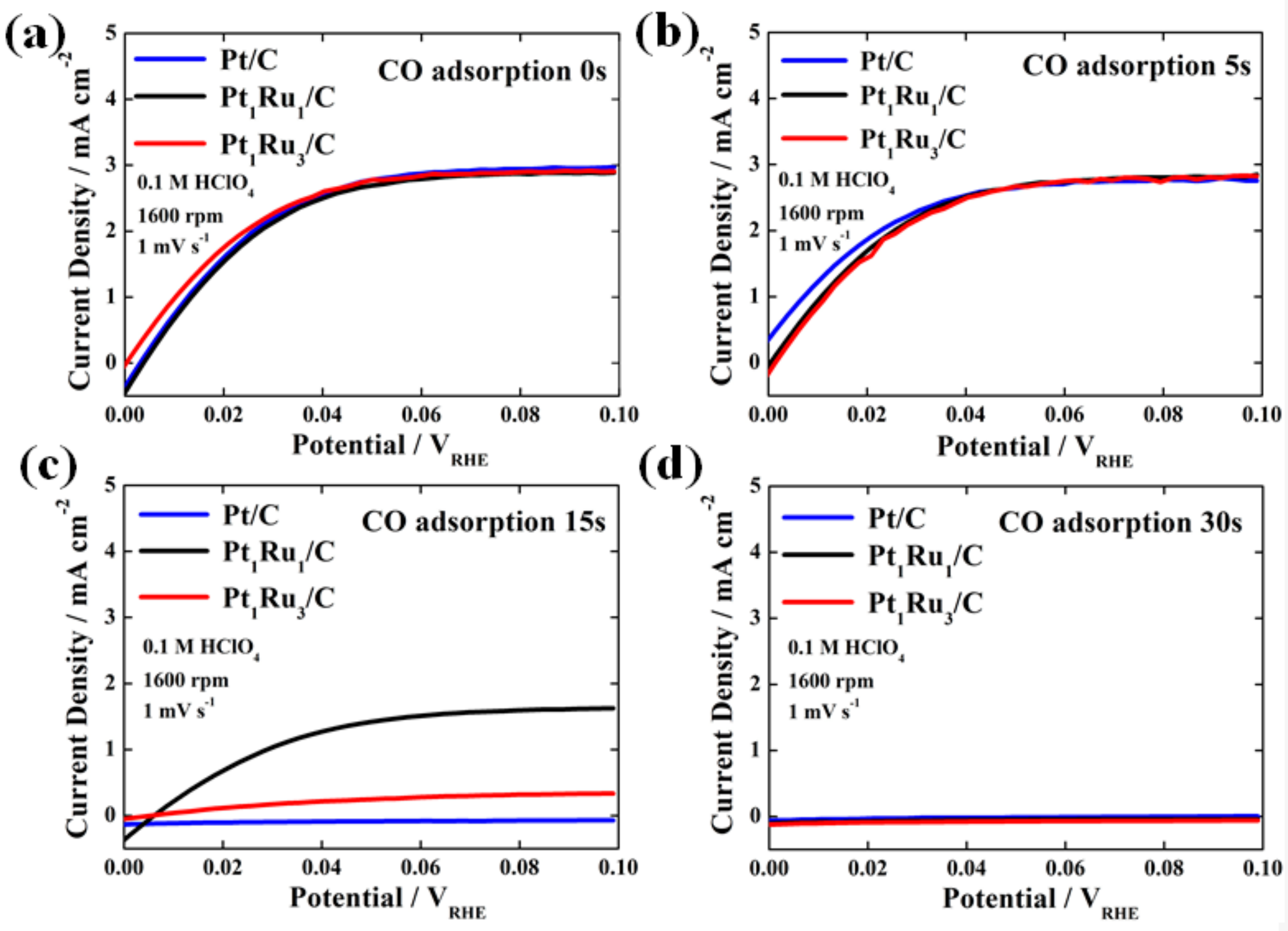
The HOR polarization curves for the prepared catalysts depending on the CO adsorption time are presented in Figure 4a–d. In Figure 4a, it is noted that the HOR curves of Pt/C, Pt1Ru1/C, and Pt1Ru3/C catalysts without CO adsorption show no noticeable difference. Similarly, when the CO adsorption time is 5 s in Step (2) shown in Figure 3, their HOR performances hardly changed because the CO adsorption time might have been too short, as shown in Figure 4b. It can be regarded as insufficient CO poisoning time in decreasing the performance of the catalysts. Interestingly, as shown in Figure 4c, we observed a clear-cut difference in performance between the two PtRu catalysts after CO was adsorbed onto the catalysts for 15 s in Step (2), although the HOR current of Pt/C without CO tolerance was zero. Notably, after 15 s of CO adsorption, the Pt1Ru1/C catalyst with an atomic ratio of 1:1 exhibited a ~50% reduction in the HOR current density, while Pt1Ru3/C showed near-zero tolerance toward CO, and the current density was drastically reduced, which is mainly attributed to severe catalyst poisoning. This result supports lower CO binding energy (higher CO oxidation reaction activity) of Pt1Ru1/C, confirmed by the CO stripping analysis, as shown in Figure 1c, and proves that Pt1Ru1 alloy has much higher CO tolerance compared to Pt1Ru3 [25,26]. Furthermore, when we increased the CO adsorption time to 30 s in Step (2), Pt1Ru1/C, as well as Pt1Ru3/C and Pt/C, indicated no HOR current since most active sites in both samples were completely poisoned by CO molecules, as shown in Figure 4d.
Consequently, it is worth noting that, in our evaluation protocol, 15 s was the optimum time for the CO adsorption to clearly confirm the difference in electrochemical properties of catalysts with low CO binding energy and sufficiently high CO tolerance. To further ascertain that 15 s CO adsorption is the optimum time clearly demonstrating the CO tolerance of PtRu catalysts, CO stripping analyses of all catalysts with different CO adsorption times were conducted again after the HOR tests and the corresponding CO coverage was calculated from the results, as shown in Figure S3. To investigate the change in CO coverage, the CO oxidation peak area obtained after 900 s of CO adsorption for each sample was served as a standard area (100%) with the catalyst surface completely covered by CO. From the CO stripping analyses, it was revealed that the CO coverage on the catalyst surface was controlled depending on the CO binding energy. As expected, in the case of CO adsorption for 15 s as the optimum value, the difference in CO coverage among the samples was apparent.

4. Conclusions

A facile and accurate test protocol, which combines short-term chronoamperometry and a simple HOR test, was proposed to evaluate the CO tolerance of catalysts with low CO binding energy and sufficiently high CO tolerance at room temperature. In this protocol, the degree of the catalyst poisoning was systematically controlled by changing the CO adsorption time with 100% CO gas. After the CO adsorption, the HOR polarization curve was obtained and compared with that measured in a pure H2 atmosphere without CO. To prove the application feasibility of the proposed evaluation protocol, the electrochemical properties of two representative PtRu (Pt1Ru1/C and Pt1Ru3/C) alloy catalysts with different atomic ratios of Pt to Ru were intensively studied. The conventional chronoamperometry showed no drastic difference in CO tolerance in both samples since they have sufficiently low CO binding energy and high CO tolerance as evidenced from the CO stripping curves and chronoamperograms, respectively. In sharp contrast, using the proposed test protocol, the CO tolerance of the catalysts were sensitively changed depending on the CO adsorption time. Especially, when the CO adsorption time was 15 s (the optimum condition), the HOR polarization curves of Pt1Ru1/C and Pt1Ru3/C showed a noticeable difference in CO tolerance even at room temperature. Accordingly, we believe that the present work will support the development of a wide variety of Pt-based alloy catalysts showing high CO tolerance and may further provide insights into the improvement of conventional electrochemical methods.

Supplementary Materials

The following are available online at https://www.mdpi.com/2079-4991/9/10/1425/s1, Figure S1: TEM image, elemental maps of Pt and Ru, and the corresponding EDX spectrum of (a) Pt1Ru1 and (b) Pt1Ru3 nanoparticles; Figure S2: Chronoamperograms of Pt/C, Pt1Ru1/C, and Pt1Ru3/C measured switching a bubbling gas (H2 and 100% CO gases) in 0.1 M HClO4 at a constant potential of 0.05 VRHE for 150 s at a rotation speed of 1600 rpm. For the CO adsorption on the catalyst surface, 100% CO was supplied into the electrolyte for (a) 0 s, (b) 5 s, (c) 15 s, and (d) 30 s; Figure S3: CO stripping curves of (a) Pt/C, (c) Pt1Ru1/C, and (e) Pt1Ru3/C measured after the CO adsorption for 5, 15, 30, and 900 s. Change in the CO coverage (%) on the catalyst surfaces for (b) Pt/C, (d) Pt1Ru1/C, and (f) Pt1Ru3/C estimated from the corresponding CO stripping curves.

Author Contributions

Conceptualization, J.M., A.A.J., and N.J.; data curation, J.M., A.A.J., and N.J.; formal analysis, J.M., A.A.J., and N.J.; investigation, J.M., A.A.J., and N.J.; methodology, J.M., A.A.J., Y.K., and N.J.; visualization, J.M., A.A.J., and N.J.; writing-original draft, J.M. and A.A.J.; writing-review & editing, J.M., A.A.J., Y.K., and N.J.; funding acquisition, N.J.; supervision, N.J.

Funding

This work was supported by the Korea Institute of Energy Technology Evaluation and Planning (KETEP) and the Ministry of Trade, Industry & Energy (MOTIE) of the Republic of Korea (No. 20173010032100). This work was also supported by the National Research Foundation of Korea (NRF) grant funded by the Korean government (MSIP) (No. 2018R1C1B6007453, 2018M1A2A2061991) and by the KIST Institutional Program.

Conflicts of Interest

The authors declare no conflict of interest.

References

  1. Qingfeng, L.; Ronghuan, H.; Jens, O.J.; Niels, J.B. Approaches and recent development of polymer electrolyte membranes for fuel cells operating above 100 °C. Chem. Mater. 2003, 15, 4896–4915. [Google Scholar]
  2. Sharma, M.; Jang, J.H.; Shin, D.Y.; Kwon, J.A.; Lim, D.H.; Choi, D.Y.; Sung, H.K.; Jang, J.H.; Lee, S.Y.; Lee, L.Y.; et al. Work function-tailored graphene via transition metal encapsulation as highly active and durable catalyst for oxygen reduction reaction. Energy Environ. Sci. 2019, 12, 2200–2211. [Google Scholar] [CrossRef]
  3. Jang, J.H.; Sharma, M.; Choi, D.I.; Kang, Y.S.; Kim, Y.J.; Min, J.H.; Sung, H.K.; Jung, N.G.; Yoo, S.J. Boosting fuel cell durability under shut-down/start-up conditions using hydrogen oxidation-selective metal-carbon hybrid core-shell catalyst. ACS Appl. Mater. Interfaces 2019, 11, 27735–27742. [Google Scholar] [CrossRef] [PubMed]
  4. Lulianelli, A.; Ribeirinha, P.; Mendes, A.; Basile, A. Methanol steam reforming for hydrogen generation via conventional and membrane reactors: A review. J. Renew. Sustain. Ener. 2014, 29, 355–368. [Google Scholar] [CrossRef] [Green Version]
  5. Boyano, A.; Blanco-Marigorta, A.M.; Morosuk, T.; Tsatsaronis, G. Exergoenvironmental analysis of a steam methane reforming process for hydrogen production. Energy 2011, 36, 2202–2214. [Google Scholar] [CrossRef]
  6. Philippe, T.; Robert, D.; Bernard, C.; Christophe, C.; Severine, R.; Claude, L. Poisoning of Pt/C catalysts by CO and its consequences over the kinetics of hydrogen chemisorption. Appl. Catal. B Environ. 2009, 92, 280–284. [Google Scholar]
  7. Xuan, C.; Zheng, S.; Nancy, G.; Zhang, L.; Zhang, J.; Datong, S.; Zhong, S.L.; Wang, H.; Shen, J. A review of PEM hydrogen fuel cell contamination: Impacts, mechanisms, and mitigation. J. Power Sources 2007, 165, 739–756. [Google Scholar]
  8. Hsieh, Y.C.; Zhang, Y.; Su, D.; Volkov, V.; Si, R.; Wu, L.; Zhu, Y.; An, W.; Liu, P.; He, P.; et al. Ordered bilayer ruthenium–platinum core-shell nanoparticles as carbon monoxide-tolerant fuel cell catalysts. Nat. Commun. 2013, 4, 2466. [Google Scholar] [CrossRef] [PubMed]
  9. Zhang, L.; Kim, J.; Zhang, J.; Nan, F.; Gauquelin, N.; Botton, G.A.; He, P.; Bashyam, R.; Knights, S. Ti4O7 supported Ru@Pt core–shell catalyst for CO-tolerance in PEM fuel cell hydrogen oxidation reaction. Appl. Energ. 2013, 103, 507–513. [Google Scholar] [CrossRef]
  10. Jackson, A.; Strickler, A.; Higgins, D.; Jaramillo, T. Engineering Ru@Pt Core-Shell Catalysts for Enhanced Electrochemical Oxygen Reduction Mass Activity and Stability. Nanomaterials 2018, 8, 38. [Google Scholar] [CrossRef]
  11. Rigdon, W.A.; Huang, X. Carbon monoxide tolerant platinum electrocatalysts on niobium doped titania and carbon nanotube composite supports. J. Power Sources 2014, 272, 845–859. [Google Scholar] [CrossRef]
  12. Lee, M.J.; Kang, J.S.; Kang, Y.S.; Chung, D.Y.; Shin, H.J.; Ahn, C.Y.; Park, S.B.; Kim, S.j.; Lee, K.S.; Sung, Y.E. Understanding the bifunctional effect for removal of CO poisoning: Blend of a platinum nanocatalyst and hydrous ruthenium oxide as a model system. ACS Catal. 2016, 6, 2398–2407. [Google Scholar] [CrossRef]
  13. Liu, P.; Logadottir, A.; Nørskov, J.K. Modeling the electro-oxidation of CO and H2/CO on Pt, Ru, PtRu and Pt3Sn. Electrochim. Acta. 2003, 48, 3731–3742. [Google Scholar] [CrossRef]
  14. Lopes, P.P.; Ticianelli, E.A. The CO tolerance pathways on the Pt–Ru electrocatalytic system. J. Electroanal. Chem. 2010, 644, 110–116. [Google Scholar] [CrossRef]
  15. Roth, C.; Papworth, A.J.; Hussain, I.; Nichols, R.J.; Schiffrin, D.J. A Pt/Ru nanoparticulate system to study the bifunctional mechanism of electrocatalysis. J. Electroanal. Chem. 2005, 581, 79–85. [Google Scholar] [CrossRef]
  16. Sugimoto, W.; Aoyama, K.; Kawaguchi, T.; Murakami, Y.; Takasu, Y. Kinetics of CH3OH oxidation on PtRu/C studied by impedance and CO stripping voltammetry. J. Electroanal. Chem. 2005, 576, 215–221. [Google Scholar] [CrossRef]
  17. Dickinson, E.J.F.; Streeter, I.; Compton, R.G. Theory of chronoamperometry at cylindrical microelectrodes and their arrays. J. Phys. Chem. C 2008, 31, 11637–11644. [Google Scholar] [CrossRef]
  18. Yuan, Y.; Wang, L.; Amemiya, S. Chronoamperometry at micropipet electrodes for determination of diffusion coefficients and transferred charges at liquid/liquid interfaces. Anal. Chem. 2004, 76, 5570–5578. [Google Scholar] [CrossRef] [PubMed]
  19. Ham, D.J.; Kim, Y.K.; Han, S.H.; Lee, J.S. Pt/WC as an anode catalyst for PEMFC: Activity and CO tolerance. Catal. Today 2008, 132, 117–122. [Google Scholar] [CrossRef]
  20. Xi, J.; Wang, J.; Yu, L.; Qiu, X.; Chen, L. Facile approach to enhance the Pt utilization and CO-tolerance of Pt/C catalysts by physically mixing with transition-metal oxide nanoparticles. Chem. Commun. 2007, 16, 1656–1658. [Google Scholar] [CrossRef] [PubMed]
  21. Guo, X.; Guo, D.J.; Wang, J.S.; Qiu, X.P.; Chen, L.Q.; Zhu, W.T. Using phosphomolybdic acid (H3PMo12O40) to efficiently enhance the electrocatalytic activity and CO-tolerance of platinum nanoparticles supported on multi-walled carbon nanotubes catalyst in acidic medium. J. Electroanal. Chem. 2010, 638, 167–172. [Google Scholar] [CrossRef]
  22. Li, M.; Pan, Y.; Guo, X.; Liang, Y.; Wu, Y.; Wen, Y.; Yang, H. Pt/single-stranded DNA/graphene nanocomposite with improved catalytic activity and CO tolerance. J. Mater. Chem. A 2015, 19, 10353–10359. [Google Scholar] [CrossRef]
  23. Martinez, H.V.; Rodriguez, J.L.; Tsiouvaras, N.; Pena, M.A.; Fierro, J.L.G.; Pastor, E. Novel synthesis method of CO-tolerant PtRu−MoOx nanoparticles: Structural characteristics and performance for methanol electrooxidation. Chem. Mater. 2008, 20, 4249–4259. [Google Scholar] [CrossRef]
  24. González-Hernández, M.; Antolini, E.; Perez, J. Synthesis, Characterization and CO Tolerance Evaluation in PEMFCs of Pt2RuMo Electrocatalysts. Catalysis 2019, 9, 61. [Google Scholar] [CrossRef]
  25. Ianniello, R.; Schmidt, V.M.; Stimming, U.; Stumper, J.; Wallau, A. CO adsorption and oxidation on Pt and PtRu alloys: Dependence on substrate composition. Electrochim. Acta 1994, 39, 1863–1869. [Google Scholar] [CrossRef]
  26. Jeon, T.Y.; Lee, K.S.; Yoo, S.J.; Cho, Y.H.; Kang, S.H.; Sung, Y.E. Effect of Surface Segregation on the Methanol Oxidation Reaction in Carbon-Supported Pt−Ru Alloy Nanoparticles. Langmuir 2010, 26, 9123–9129. [Google Scholar] [CrossRef]
  27. Jang, Y.; Choi, K.-H.; Chung, D.Y.; Lee, J.E.; Jung, N.; Sung, Y.-E. Self-assembled dendritic Pt nanostructure with high-index facets as highly active and durable electrocatalyst for oxygen reduction. ChemSusChem 2017, 10, 3063–3068. [Google Scholar] [CrossRef]
  28. Cuesta, A.; Couto, A.; Rincón, A.; Pérez, M.C.; López-Cudero, A.; Gutiérrez, C. Potential dependence of the saturation CO coverage of Pt electrodes: The origin of the pre-peak in CO-stripping voltammograms. Part 3: Pt(poly). J. Electroanal. Chem. 2006, 586, 184–195. [Google Scholar] [CrossRef]
  29. López-Cudero, A.; Cuesta, A.; Gutiérrez, C. Potential dependence of the saturation CO coverage of Pt electrodes: The origin of the pre-peak in CO-stripping voltammograms. Part 1: Pt(111). J. Electroanal. Chem. 2005, 579, 1–12. [Google Scholar]
  30. Li, Q.; He, R.; Gao, J.A.; Jensen, J.O.; Bjerrum, N.J. The CO poisoning effect in PEMFCs operational at temperatures up to 200 °C. J. Electrochem. Soc. 2003, 150, A1599–A1605. [Google Scholar] [CrossRef]
  31. Lopes, P.P.; Freitas, K.S.; Ticianelli, E.A. CO Tolerance of PEMFC Anodes: Mechanisms and Electrode Designs. Electrocatalysis 2010, 1, 200–212. [Google Scholar] [CrossRef]
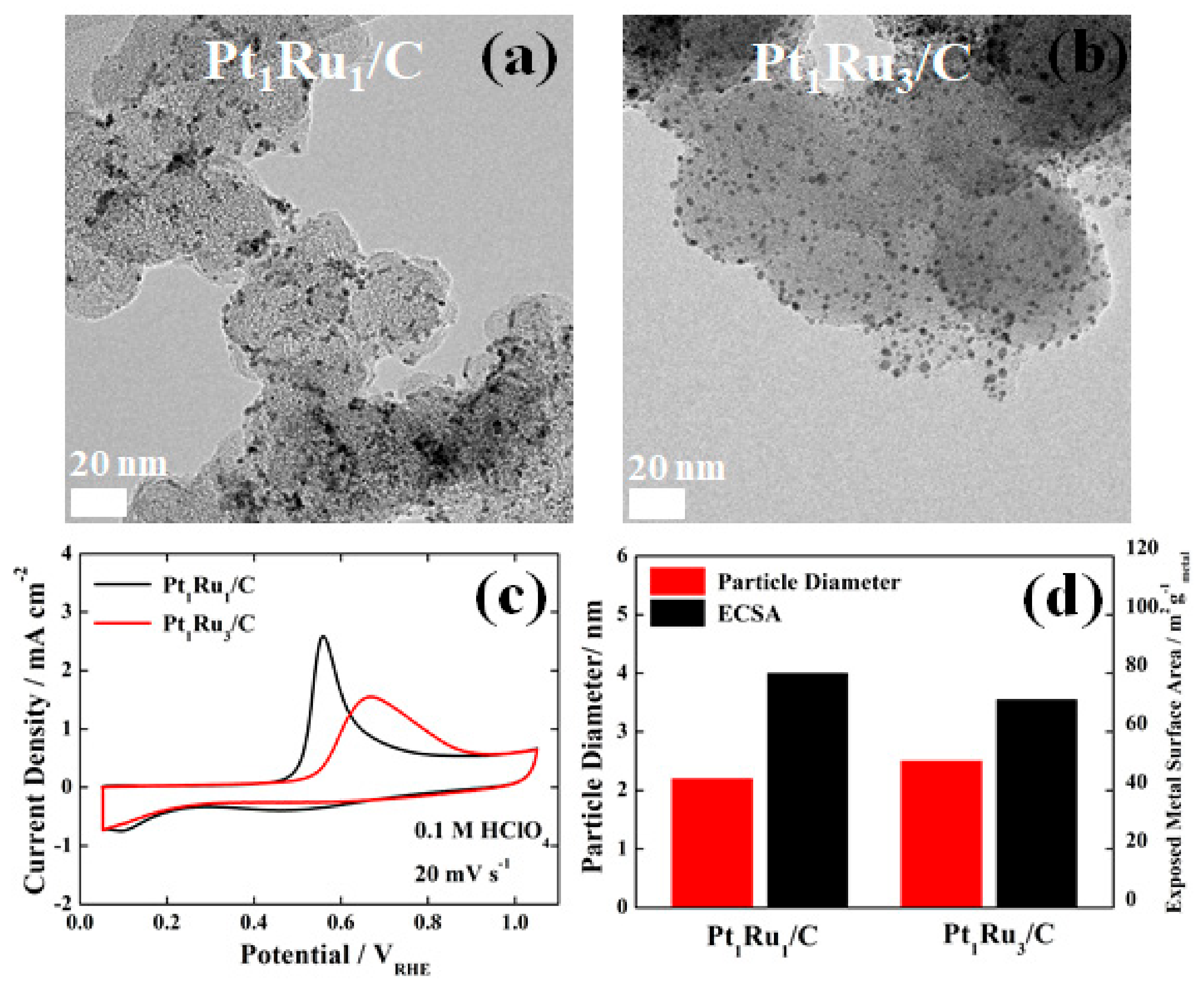
Figure 1. Transmission electron microscopy (TEM) images of (a) Pt1Ru1/C and (b) Pt1Ru3/C, (c) CO-stripping curves and (d) particle diameters and electrochemically active surface areas (ECSAs) of Pt1Ru1/C and Pt1Ru3/C.
Nanomaterials 09 01425 g001
Figure 2. Chronoamperograms of (a) Pt/C, (b) Pt1Ru1/C, and (c) Pt1Ru3/C measured in H2- and 100 ppm CO-mixed H2-saturated 0.1 M HClO4 at a constant potential of 0.05 VRHE for 7200 s.
Nanomaterials 09 01425 g002
Figure 3. Proposed test protocol to evaluate the CO tolerance and the test results of the Pt1Ru1/C catalyst as an example in each step. Step (1) chronoamperometry of catalyst in H2-saturated 0.1 M HClO4 at a constant potential of 0.05 VRHE for ~60 s, Step (2) 15 s CO adsorption on catalyst followed by H2 purging for 20 min at a constant potential of 0.05 VRHE, and Step (3) hydrogen oxidation reaction (HOR) polarization curve of catalyst in H2-saturated 0.1 M HClO4.
Nanomaterials 09 01425 g003
Figure 4. The HOR polarization curves of commercial Pt/C, Pt1Ru1/C, and Pt1Ru3/C catalysts measured in H2-saturated 0.1 M HClO4 after the CO adsorption for (a) 0 s (without CO adsorption), (b) 5 s, (c) 15 s, and (d) 30 s.
Nanomaterials 09 01425 g004