Article

Engineering Charge Transfer Characteristics in Hierarchical Cu2S QDs @ ZnO Nanoneedles with p–n Heterojunctions: Towards Highly Efficient and Recyclable Photocatalysts

1
School of Materials Science and Engineering, Changchun University of Science and Technology, Changchun 130022, China
2
Engineering Research Center of Optoelectronic Functional Materials, Ministry of Education, Changchun 130022, China
3
Changchun Institute of Optics, Fine Mechanics and Physics, Chinese Academy of Sciences, Changchun 130033, China
4
School of Engineering and Architecture, Northeast Electric Power University, Jilin City 132012, China
5
School of Materials Science and Engineering, Jilin University, Changchun 130025, China
6
Quality and Reliability Assurance Department, GLOBALFOUNDRIES (Singapore) Pte. Ltd., 60 Woodlands Industrial Park D, Street 2, Singapore 738406, Singapore
*
Authors to whom correspondence should be addressed.
Nanomaterials 2019, 9(1), 16; https://doi.org/10.3390/nano9010016
Submission received: 21 November 2018 / Revised: 18 December 2018 / Accepted: 19 December 2018 / Published: 23 December 2018
(This article belongs to the Special Issue Nanostructured Catalysts for Sustainable Applications)

Abstract

:
Equipped with staggered gap p-n heterojunctions, a new paradigm of photocatalysts based on hierarchically structured nano-match-shaped heterojunctions (NMSHs) Cu2S quantum dots (QDs)@ZnO nanoneedles (NNs) are successfully developed via engineering the successive ionic layer adsorption and reaction (SILAR). Under UV and visible light illumination, the photocatalytic characteristics of Cu2S@ZnO heterojunctions with different loading amounts of Cu2S QDs are evaluated by the corresponding photocatalytic degradation of rhodamine B (RhB) aqueous solution. The results elaborate that the optimized samples (S3 serial specimens with six cycles of SILAR reaction) by means of tailored the band diagram exhibit appreciable improvement of photocatalytic activities among all synthesized samples, attributing to the sensitization of a proper amount of Cu2S QDs. Such developed architecture not only could form p–n junctions with ZnO nanoneedles to facilitate the separation of photo-generated carries but also interact with the surface defects of ZnO NNs to reduce the electron and hole recombination probability. Moreover, the existence of Cu2S QDs could also extend the light absorption to improve the utilization rate of sunlight. Importantly, under UV light S3 samples demonstrate the remarkably enhanced RhB degradation efficiency, which is clearly testified upon the charge transfer mechanism discussions and evaluations in the present work. Further supplementary investigations illustrate that the developed nanoscale Cu2S@ZnO heterostructures also possess an excellent photo-stability during our extensive recycling photocatalytic experiments, promising for a wide range of highly efficient and sustainably recyclable photocatalysts applications.

1. Introduction

With the increasing emphasis on environmental pollution and energy shortage, photocatalytic degradation of organic pollutants in water using solar energy has become a promising route to solve those problems due to its environmental friendliness, high efficiency, and easy operation compared to traditional treatment methods, such as coagulation, adsorption, and membrane separation [1,2,3,4]. Therefore, great deals of efforts have been devoted in recent years to improve the necessitating high efficiency, long-term stability and low cost semiconductor photocatalysts [5,6,7,8,9,10]. Among various semiconductor materials, zinc oxide (ZnO) has attracted significant attention because of its superior characteristics, e.g., direct wide band gap (Eg = 3.37 eV), easy access, low-cost, low-toxic, high photosensitivity, chemical stability, tunable nanoscale size with adjustable optical and magneto-optical, as well as perfect electron mobility (205–300 cm, 2 V/s) [11,12,13,14,15,16,17,18,19]. Nevertheless, under UV light, the fast electron-hole pair recombination and photocorrosion in the single phase ZnO leads to a low photocatalytic activity, and ZnO under visible light is almost no activity by reason of the high band gap [20,21].
To overcome the drawbacks of ZnO, we need to develop a new material with better optical absorption capacity and lower tendency towards charge recombination than that of pure ZnO material. Until now, possible solutions have been tested. Metals doping (such as gold, silver, rhodium, or platinum) [22,23], metal ions doping (such as Bi or Al) [24], and nitrogen doping [25] are the most used techniques to give rise to visible light activity of the semiconductor materials, to extend their light absorption ability from UV to visible range and to feature good electron transport. Beyond that, heterojunctions, which can effectively capture the photo-generated charge carriers to improve the charge separation efficiency, decrease the surface reaction over potential, enhance apparent quantum efficiencies and provide active sites for surface redox reaction at two different reaction sites, are believed to be essential to achieving highly efficient photocatalytic performances [26,27,28,29,30,31,32,33,34,35,36,37]. Recently, semiconductor heterojunctions composed of ZnO and other metal sulfides or oxides have also been extensively studied, for example combining ZnO with Cu2O, CdS, SnO2, MoO3, and TiO2 semiconductor materials [1,2,32,33,38,39,40]. Aforementioned results demonstrate that the composites developed by coupling different semiconductor materials could exhibit collective and enhanced property by reciprocal transfer of electrons and holes from one semiconductor to the other under irradiation and, consequently, realizing a higher photocatalytic activity [41,42,43]. Copper sulfides (Cu2S), as an important p-type semiconductor due to the stoichiometric deficiency of copper in the lattice, are holding great potential applications in diverse fields including cold cathodes [44], solar cells [45], nanoscale switches [46], chemical sensing [47] and nanoscale switches [48]. In addition, attributed to its excellent combination of a bulk band gap of 1.2 eV, an absorption coefficient of >104 cm−1, a certain thermal and chemical stability, the elemental abundance as well as low toxicity [49], Cu2S has also been considered as an ideal light absorbing material for photocatalytic [12], photothermal [50], photovoltaic [51] and optoelectronic [2] applications. The band structures of Cu2S and ZnO are sufficient to facilitate the electron transfer process. In this process, the photo-generated electrons can flow from Cu2S to ZnO, and the charge carriers become physically separated once they are generated [52]. Therefore, the Cu2S and ZnO have been selected to compose a highly catalytic efficient, stable and cost-effective p–n heterostructure.
Different preparation methods for fabrication ZnO semiconductor materials such as coprecipitation [53], micro-emulsions [54], sol-gel [55], hydrothermal routes [56], combustion [57], pulsed-laser deposition [58], spray pyrolysis [59], etc. have been used. And various synthesis methods for fabrication Cu2S semiconductor materials such as successive ion layer adsorption (SILAR) [60], physical vapor deposition (PVD) [61], hydrothermal method [62], solvothermal decomposition [63], etc. have also been tested. Of all the preparation methods, hydrothermal method for ZnO and deposition Cu2S on substrate by SILAR have been proved to be the simpler, cheaper, and less toxic methods [64].
In the present work, we report on the synthesis of p-n heterostructure comprising of ZnO nanoneedles (NNs) decorated with Cu2S quantum dots (QDs) by a low-cost, easy to operate and environmentally friendly two step method. The first step is to prepare ZnO NNs by hydrothermal method, and the second step is to deposit Cu2S QDs on ZnO NNs by SILAR method. The photocatalytic performances of ZnO NNs and ZnO@Cu2S nano-match-shaped heterojunctions (NMSHs) under UV and visible light irradiation were evaluated by the photocatalytic degradation of rhodamine B (RhB). The structural characteristics of ZnO@Cu2S NMSHs and the role of Cu2S QDs in improving the photocatalytic activity of ZnO NNs are the focus of the present study and discussions.

2. Materials and Methods

2.1. Materials

Ethylenediamine, Copper nitrate trihydrate (Cu(NO3)2·3H2O), sodium sulfide nonahydrate (Na2S·9H2O), RhB and other required chemicals were all analytical-grade reagents and were used as received without further purification. And all of them were obtained from Sinopharm Chemical Regent Co., Ltd. (Shanghai, China).

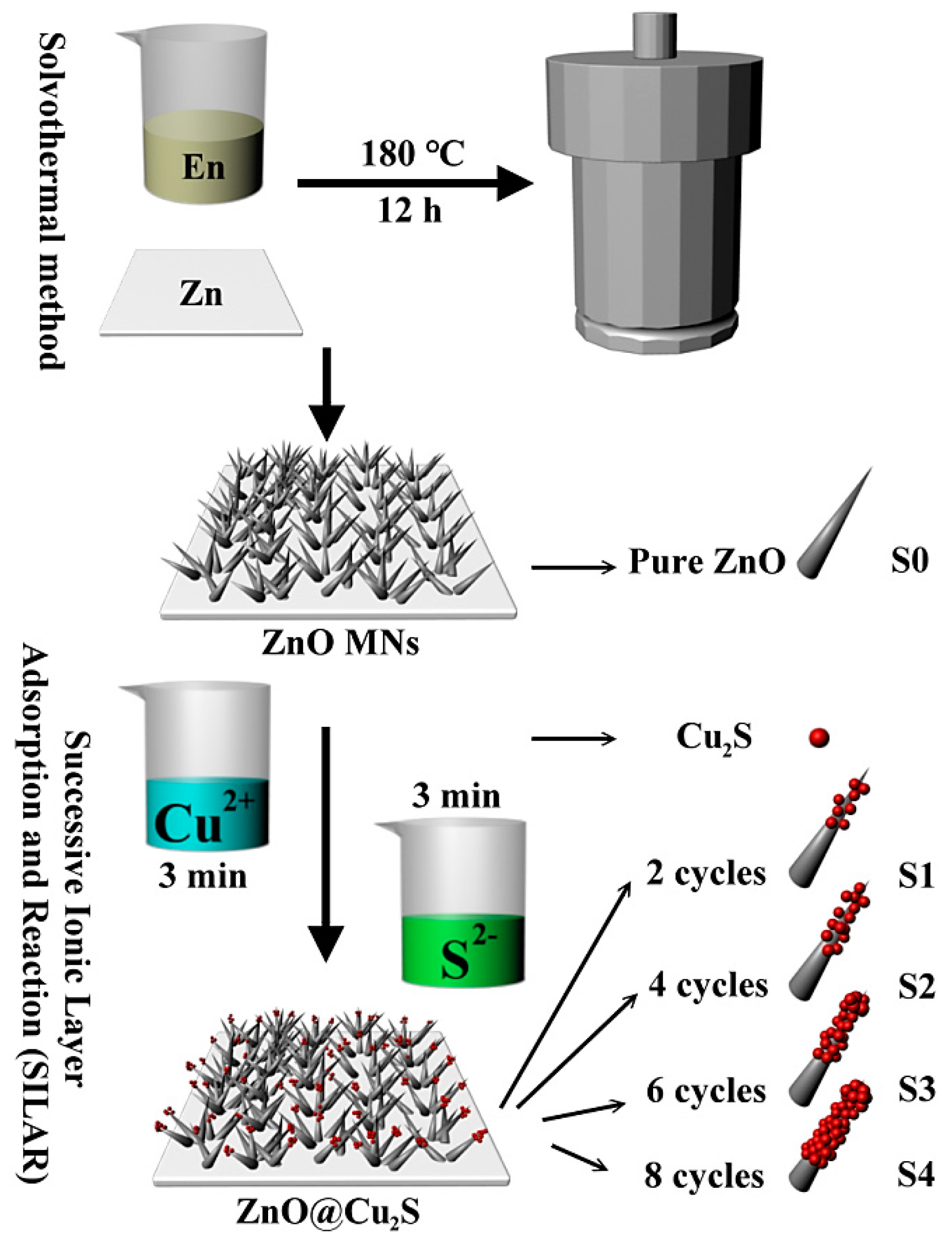
2.2. Samples Preparation

The synthesis processes of ZnO@Cu2S NMSHs can be divided into two steps: ZnO NNs growing and Cu2S coating, as shown in Figure 1.
ZnO NNs growth: Zinc sheet with the size of 1.0 cm × 1.0 cm (width × width), the thickness of 0.22 mm and the purity of 99% was used as zinc source and a substrate for direct growth ZnO NNs. First Zinc sheet was put into a mixed aqueous solution containing 5 mL ethylene diamine and 5 mL deionized water. Then, this system was transferred into a 20 mL Teflon-lined autoclave and kept at 180 °C for 12 h as Figure 1 shows. After the reaction, the autoclave was taken out and cooled down to room temperature. The products (each thin film) were thoroughly rinsed with deionized water and absolute ethanol. Ultimately, the pure ZnO NNs were obtained and labeled as S0.
Cu2S QDs synthesis and coating: Due to the quantum dots possess few atoms and small size effect, it can generate special interface effects and function under the quantum confinement effect [65,66,67,68]. In our experiments, ZnO@Cu2S NMSHs were prepared through a modified successive ionic layer adsorption and reaction (SILAR) method. Firstly, the prepared ZnO NNs were immersed into the Cu(NO3)2 (0.5 mol/L) solution and remained stationary for 3 min for adsorbing Cu2+ ions, and then the samples were taken out and washed thoroughly with deionized water to remove the excess Cu2+ ions which adsorbed weakly on the surface of samples. Secondly, we continued to place the samples in the Na2S (0.5 mol/L) solution and repeated the above operation. When the tip of ZnO NNs begun to turn black, it proved that Cu2S QDs has begun to adsorb to the ZnO NNs and the ZnO@Cu2S NMSHs were initially synthesized. In order to investigate the effect of the deposition amount of Cu2S QDs on photocatalytic performance, samples with repeating different SILAR cycle times were prepared, and the samples with two, four, six and eight SILAR cycle times were denoted as S1, S2, S3, S4, respectively. The surface of the ZnO NNs turned dark when we repeat this SILAR cycle for eight times, indicating that Cu2S QDs has completely covered the tip of the ZnO NNs and the ZnO@Cu2S NMSHs have been compounded.

2.3. Characterization

The X-ray diffraction patterns (XRD) of the as-prepared samples were measured on a D/max-2500 copper rotating-anode X-ray diffractometer (Rigaku Corporation, Tokyo, Japan) with Cu Kα radiation of wavelength λ = 1.5406Å (40 kV, 200 mA). The surface morphologies of the as-prepared samples were characterized by a field emission scanning electron microscope (FESEM, 7800F, JEOL Ltd., Tokyo, Japan), and the elemental composition was estimated by energy-dispersive X-ray spectroscopy (EDX) (JEOL Ltd., Tokyo, Japan). Transmission electron micrographs (TEM) and high-resolution transmission electron microscopy (HRTEM) images were taken on a FEI Tenai G2 F20 electron microscope (JEOL Ltd., Tokyo, Japan) equipped with an X-ray energy dispersive spectrometer (EDS) (JEOL Ltd., Tokyo, Japan). Chemical components and the binding energies of ZnO NNs and the ZnO@Cu2S NMSHs were analyzed by X-ray photoelectron spectroscopy (XPS) (Thermo Scientific ESCALAB 250Xi A1440 system, Thermo Fisher Scientific, Waltham, MA, USA). Photoluminescence (PL) spectra were investigated at room temperature on a Renishaw in Via micro-PL spectrometer (Renishaw, London, UK) at room temperature (λex = 325 nm, He-Cd laser). The UV-Vis diffuse reflection spectra (DRS) of the samples (S0-S4) were measured by an UV-Vis spectrophotometer (UV-5800PC, Shanghai Metash Instruments Co., Ltd., Tokyo, Japan).

2.4. DRS Test and Photocatalyic Test

DRS test: First, install the integrating sphere attachment. Then, in the measurement method of the UV Probe software, the measurement method is set to absorbance, and the measurement wavelength range is set. A standard sample is placed on the sample sit of the integrating sphere. Baseline correction was performed over the measurement wavelength range. Finally, the standard sample of the integrating sphere is removed and replaced with the sample to be measured.
Photocatalytic test: The photocatalytic activities of the obtained samples were measured by the degradation of RhB aqueous solution under UV and visible light irradiation. A 250 W high-pressure mercury lamp with average light intensity of 22.11 mW/cm2 (main wavelength 365 nm) was used as UV source and a 300 W Xe arc lamp with the intensity of 5 W·cm−2 were used as the visible light source by a 420nm cutoff filter. After washing with the RhB aqueous solution (2 mg/L), the square substrates (covered with ZnO NNs or ZnO@Cu2S NMSHs) with the size of 1.0 cm × 1.0 cm (width × width) were immersed into the RhB aqueous solution for 20 min in the dark to reach an adsorption-desorption equilibrium between the catalysts and RhB molecules. After that, the light source was switched on, and then 2mL of aliquots was withdrawn from the irradiated suspension every 20 min. The concentrations of RhB before and after different irradiation intervals were analyzed by a UV-Vis spectrophotometer with 14 cm away between the cuvettes and the light source, and then the percentage degradation was calculated.

3. Results and Discussion

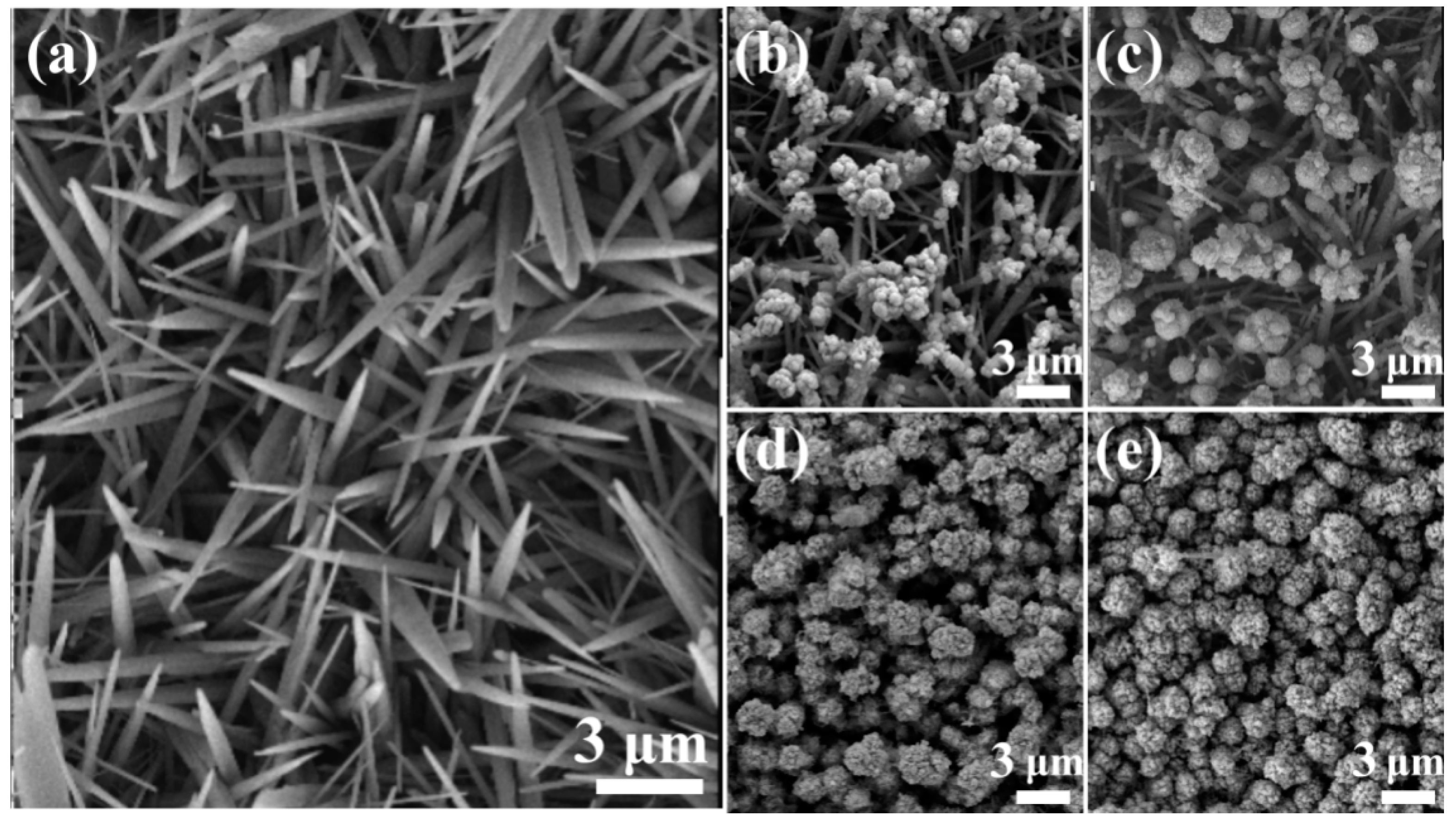
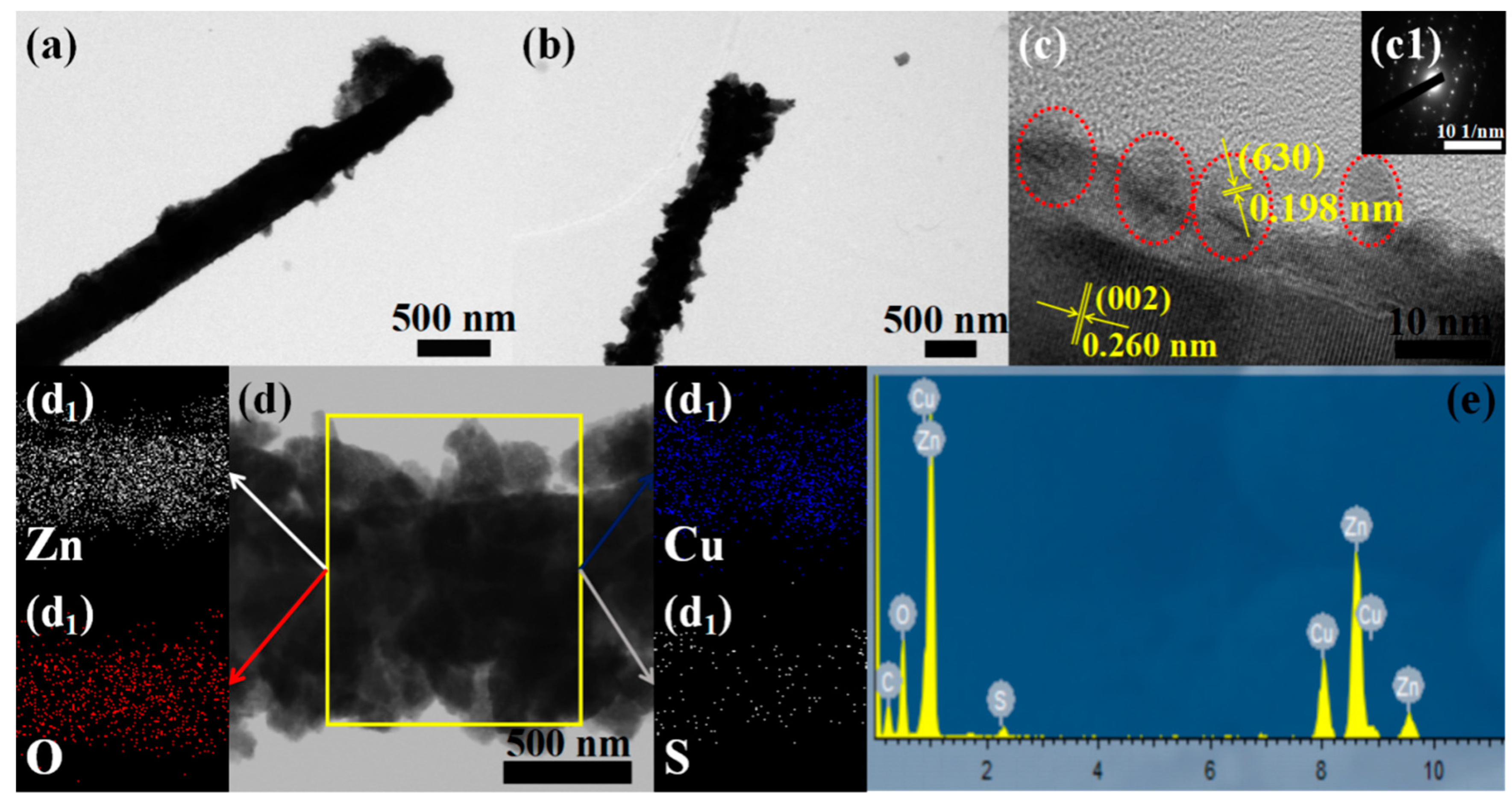
3.1. Morphologies and Phase Structures

Figure 2a,b show the XRD and partially magnified XRD patterns (the black rectangle in Figure 2a) of ZnO NNs (S0) and ZnO@Cu2S NMSHs (S1–S4). The pronounced diffraction peaks were exhibiting the crystalline nature, so the average crystallite size was determined using the Scherrer’s formula, D = 0.9 λ/β Cosθ, where λ is the wavelength of x-ray radiation, β is the full width of half maximum of the peak at diffracting angle θ. The average crystallite size of the S0–S4 samples remained virtually unchanged as the increasing amount of Cu2S QDs in ZnO@Cu2S NMSHs, which indicate that copper is not doped into the bulk phase of ZnO but exists in the form of sulfide [69]. It can be clearly seen from Figure 2a that all the diffraction peaks of as-synthesized S0, S1, and S2 samples agree well with the hexagonal wurtzite phase structure of ZnO (JCPDS card No.36-1451) [70], except for some peaks (marked with blue squares) coming from the Zn (JCPDS No. 87-0713) substrate. However, these diffraction peaks of Cu2S are absence in the XRD patterns of S1 and S2 samples (Figure 2b), which may be attributed to the low loading amount of Cu2S nanomaterials loaded on the surface of ZnO. This will be further discussed by the SEM and TEM test. As the XRD patterns of S3 and S4 samples shown, the diffraction peaks of as-synthesized ZnO@Cu2S NMSHs observed at 2θ values of 31.7°, 34.3°, 36.2°, 47.4°, 56.5°, and 62.7° are matched well to (100), (002), (101), (102), (110), and (103) planes of the hexagonal wurtzite ZnO (space group p63mc, JCPDS card No.36-1451) [70], meanwhile the observed at 2θ values of 37.1°, 45.6°, and 47.9° could be indexed to (204), (630), and (106) planes of chalcocite Cu2S phase (JCPDS card No. 73-1138). No characteristic peaks of other impurities were detected, indicating that the films were prepared as we designed.
Field emission scanning electron microscopy (FESEM) images morphology evolution investigations were carried out to observe the amount and morphology of ZnO NNs and Cu2S QDs in the ZnO@Cu2S NMSHs. Figure 3a reveals the FESEM image of the pure ZnO NNs (S0) and Figure 3b–e reveal the FESEM images of ZnO@Cu2S NMSHs synthesized with SILAR method for two, four, six, and eight cycle times, respectively. As shown in Figure 3a, the ZnO nanocrystals with very clean and smooth surface exhibit needle-like structure, and the diameter and length range of the pure ZnO NNs (S0) are 340~530 nm and up to 5.3~10.6 μm, respectively. From Figure 3b–e we can see that the shapes of S1–S4 samples are like “matches” with different sizes of heads proving that the Cu2S QDs has been deposited on the ZnO NNs. As the loading amount of Cu2S QDs was improved, the average sizes of the head of these “matches” samples (S1–S4) grow to 670 nm, 1.3, 2.0, and 2.3 μm, respectively. When the SILAR reaction cycle reaches six times (S3), the surfaces of ZnO NNs were nearly covered by the Cu2S QDs and the nanoneedles structure of ZnO was hardly detected (Figure 3d). Meanwhile, plenty of Cu2S QDs became to aggregate together (Figure 3d). Particularly, when the SILAR reaction cycle reaches eight times (S4), the heads of those “matches” have been tightly connected to each other to form a Cu2S shell layer that closely covers ZnO nanoneedles.
In order to further identify the morphology and detailed structure of the ZnO@Cu2S NMSHs and reveal its chemical element composition, TEM (Figure 4a) test of S1 sample and TEM (Figure 4b,d), HRTEM (Figure 4c), selected area electron diffraction (SAED, Figure 4c1), EDX, and EDS elemental mappings for Zn, O, Cu, and S (Figure 4e and Figure 4d1–d4) analysis of S3 sample was carried out. When Cu2S was deposited to form ZnO@Cu2S NMSHs (S1 and S3 samples), it was observed in Figure 4a,b that a number of Cu2S QDs were selectively grown on the tips of ZnO NNs to form a match-like morphology composites, and as the number of Cu2S QDs deposition increases, the size of the top end of the match-shaped nanomaterial increases from 680 to 910 nm. The HRTEM images of the ZnO@Cu2S NMSHs (Figure 4c) and the TEM images (Figure 4d) show an apparent contrast between the inner core and the outer shell, which suggest the existence of a core-shell structure. The HRTEM image in Figure 4c clearly shows that the shell has an interlayer spacing of 0.198 nm, which is in agreement with the lattice spacing of the (630) planes of the chalcocite Cu2S (d(630) = 0.197 nm for bulk Cu2S); the core displays an interlayer spacing of 0.26 nm, which agrees well with the lattice spacing of the (002) planes of the hexagonal wurtzite-type ZnO (d(002) = 0.26 nm for bulk wurtzite ZnO). At the same time, we can also get the information from Figure 4c that the as-prepared Cu2S QDs with an average diameter of 7 nm are uniformly distributed on the surface of the ZnO NNs, and the Cu2S QDs and the ZnO NNs grow preferentially along the [630] and [002] direction, respectively. The corresponding SAED pattern in Figure 4c1 reveals that ZnO NNs has a single crystal-like structure and Cu2S QDs has a polycrystalline structure which further confirms that the sample we prepared is a composite material consisting of ZnO and Cu2S. Figure 4d was selected to do the EDS elemental mapping test and the Figure 4d1–d4 display the EDS elemental mapping images of Zn, O, Cu and S, respectively. As shown in Figure 4d1–d4, the distributions of Zn, O, Cu, and S atoms are uniformly dispersed and the Zn element is concentrated only at the core region while the Cu signal is dispersed in the entire nanoneedles, which again confirms the core-shell configurations with the Cu2S sheath have been generated. Compare Figure 4d1 with Figure 4d3, the distribution density of the S element is much lower than that of the Cu element, which indicates that the valence of Cu is lower than S. Figure 4e is the EDX of S3. The results show that the sample contained Zn, O, Cu, and S elements, which further confirmed that the sample may be composed of ZnO NNs and Cu2S QDs, and the surface chemical states will be further confirmed by XPS analysis.
The XPS measurement was performed to investigate the surface elemental composition and elemental valences of ZnO@Cu2S NMSHs (Figure 5a–e). All binding energy values in the XPS spectra were calibrated according to the information of C 1s (284.6 eV) [71]. The presence of C element mainly originated from the oil pump owing to vacuum treatment [72]. In the survey spectra of ZnO@Cu2S NMSHs (Figure 5a), all elements, namely Cu, Zn, O, and S, are detected with strong characteristic peaks. In addition, the atom ratio of the Cu (24.08, expressing in the illustration of Figure 5a) is two times higher than the S (11.89, expressing in the illustration of Figure 5a) in ZnO@Cu2S NMSHs, which has confirmed that the Cu2S QDs phase exists in ZnO@Cu2S NMSHs. The Zn 2p regions of the XPS spectra (Figure 5b) consist of two peaks centered at 1021.9 and 1044.9 eV, which were characteristics of the Zn 2p3/2 and Zn 2p1/2 of ZnO [73]. The Zn 2p core level dipoles induced by the spin-orbit coupling are typical of ZnO materials in terms of binding energy, peak shape, and peak separation which is 23 eV [74]. The peak centered at 531.2 eV (Figure 5c) corresponds to the O 1s peak of ZnO [75]. The Cu 2p peaks located at 932.3 eV and 952.2 eV (Figure 5d) are consistent with the binding energies of the Cu 2p3/2 and Cu 2p1/2 for Cu+ in Cu2S, respectively [76]. For the ZnO@Cu2S NMSHs, both the asymmetric Cu 2p peaks with shoulders on the higher binding energy sides of the Cu 2p lines and the satellite peaks which can be found at the higher binding energy direction in Figure 5d can prove that the Cu2+ ions are also present in the samples [77,78]. As the illustration of Figure 5d expressed, when the valence of Cu is +1, the outermost electronic configuration of Cu+ ions is d10 arranged with stably and fully paired, so it is difficult to excite the electrons in the d-orbital. However, if the Cu is +2 state, there will be one unpaired electron in the outermost 3d-orbital which can easily interact with an out-going electron, absorbed an amount of energy and then jump to a higher energy level. Therefore, if a higher binding energy satellite peaks can be detected by the XPS detector, it is proved that the Cu2+ ions exist in the samples [79,80]. Two peaks which are located at 161.3 eV and 162.4 eV (Figure 5e) can be ascribed to S 2p3/2 and S 2p1/2 of S2−, respectively [81].

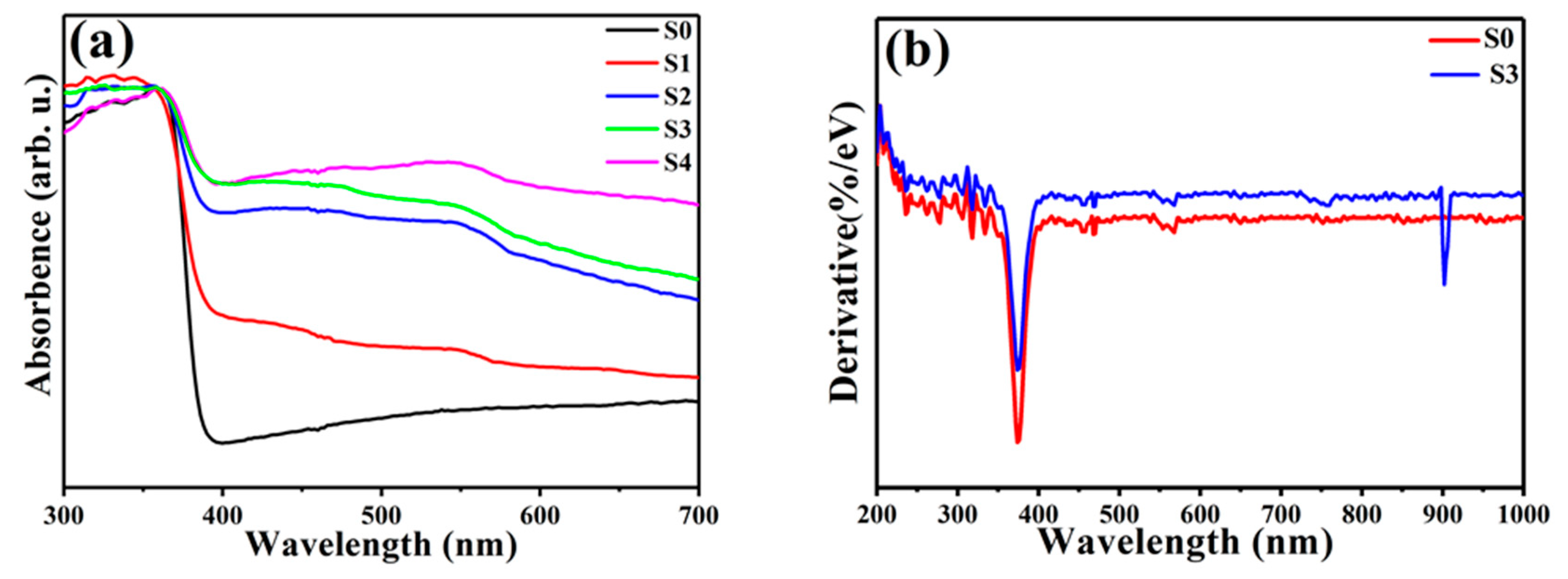
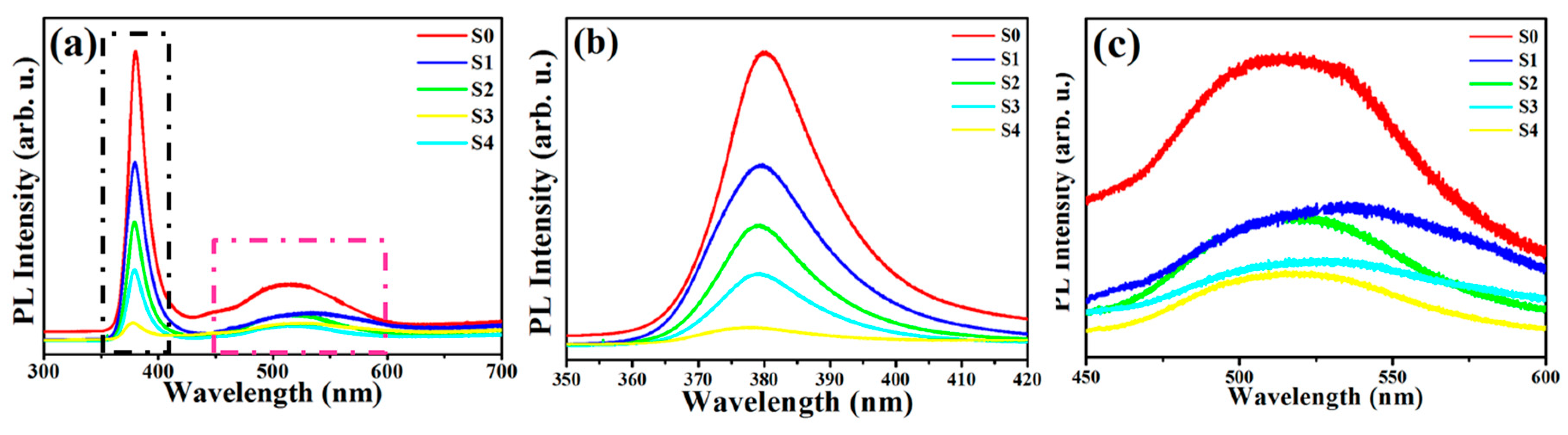
3.2. Optical Properties

Figure 6a,b shows the room temperature UV-Vis diffuse reflectance spectra in the presence of ZnO NNs (S0) and ZnO@Cu2S NMSHs with different SILAR cycle times (S1–S4) and the corresponding derivative curves of ZnO NNs (S0) and ZnO@Cu2S NMSHs with six SILAR cycle times (S3), respectively. As Figure 6a shows, the spectrum of pure ZnO NNs (S0) displayed only a sharp UV absorption edge at around 386 nm. The absorption onsets of other samples (S1–S4) are also located at around 386 nm, corresponding to the absorption of ZnO NNs in ZnO@Cu2S NMSHs [82]. The almost identical absorption edges of pure ZnO and ZnO@Cu2S NMSHs indicate that copper is not doped into the bulk phase of ZnO but exists in the form of sulfide so that composite material is formed with ZnO and Cu2S [83]. Compared with the single ZnO NNs, ZnO@Cu2S NMSHs also showed an absorption band in the region of 400~700 nm, which should be ascribed to the contribution of Cu2S, since its appropriate energy band gap (1.2 eV) structure and the high optical absorption coefficient [84]. It is worth noting that the absorption intensity of this band gradually increased with the increasing amount of Cu2S QDs in ZnO@Cu2S NMSHs. Figure 6b shows the spectra of S0 and S3 samples deriving from UV–Vis diffuse reflectance spectra (Figure 6a). For S0 sample, only one distinct peak at 374.7 nm (3.31 eV) is observed, which is a characteristic of wurtzite ZnO. For S3 sample, there are two peaks can be observed from the derivative spectrum, which are respectively located at 374.7 nm (3.31 eV) and 902.3 nm (1.37 eV). The peaks at 3.31 and 1.37 eV are ascribed to ZnO NNs and Cu2S QDs, respectively. Compared with bulk Cu2S material, the band gap of Cu2S QDs in ZnO@Cu2S NMSHs moves towards higher energy, which may be attributed to quantum size effects [85,86,87].
Figure 7a–c show the PL spectrum of ZnO NMs and ZnO@Cu2S NMSHs at room temperature. It was observed from Figure 7b that the as-prepared ZnO NNs and ZnO@Cu2S NMSHs displayed a strong blue emission peak centered at 380 nm, which was close to the near band edge emission of ZnO (ca. 368 nm) due to the recombination of free excitons through an exciton–exciton collision process [88,89,90]. However, besides the fundamental ZnO emission, the green region peaks from 450 nm to 600 nm detected in the PL spectra (Figure 7c) can be generally attributed to oxygen vacancies and surface interstitial oxygen [89,90,91,92], which generally revealed that a number of trapped states have been formed in the forbidden band of ZnO [93]. Such surface defects could act as the recombination centers of photoexcited electron-hole pairs, leading to lower the photocatalytic efficiency. It can be seen from Figure 7a–c, the trend of PL spectrum of ZnO@Cu2S NMSHs with different SILAR cycle times is similar to that of single ZnO NNs, but the intensity of those two peaks of ZnO@Cu2S NMSHs was lower than the single ZnO NNs, verifying that the ZnO@Cu2S NMSHs have higher charge separation efficiency than the pure ZnO NNs. The peak strength has been declining until the SILAR cycle time of Cu2S QDs in ZnO@Cu2S NMSHs reaches six, which proves that an appropriate increasing amount of Cu2S QDs is beneficial to form p–n junctions to promote charge separation. It was reported by Yubin Chen’s group that Cu2S could interact with defect states on the surface of CdS and meanwhile quench the emission by forming p–n interfacial junctions. In the p–n nano-match-shaped heterojunctions ZnO@Cu2S, similar mechanism can be expected. In other words, it is considered that Cu2S QDs can form heterojunctions with ZnO NNs and interact with the surface defects of ZnO (such as oxygen vacancies and surface interstitial oxygen) to quench the surface trap states emission between 450 and 600 nm and increase the charge separation efficiency in ZnO@Cu2S NMSHs. When the SILAR reaction cycle reaches eight times (S4), the aggregation of Cu2S QDs occurred, and the peak strength of the two PL peaks does not continue to decline but begins to rise because the aggregation of Cu2S QDs could restrict the formation of more p–n junctions and the grain boundaries of Cu2S QDs would act as the recombination centers, lowing the charge separation [94].

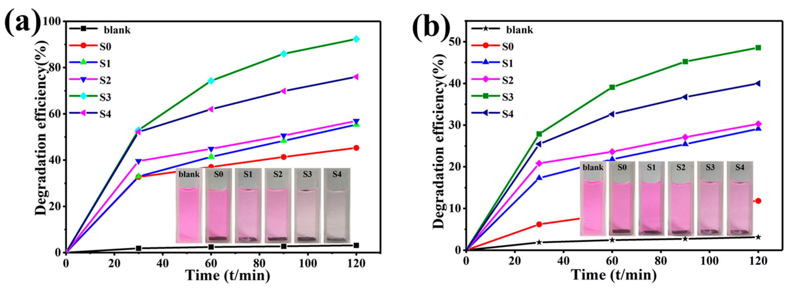
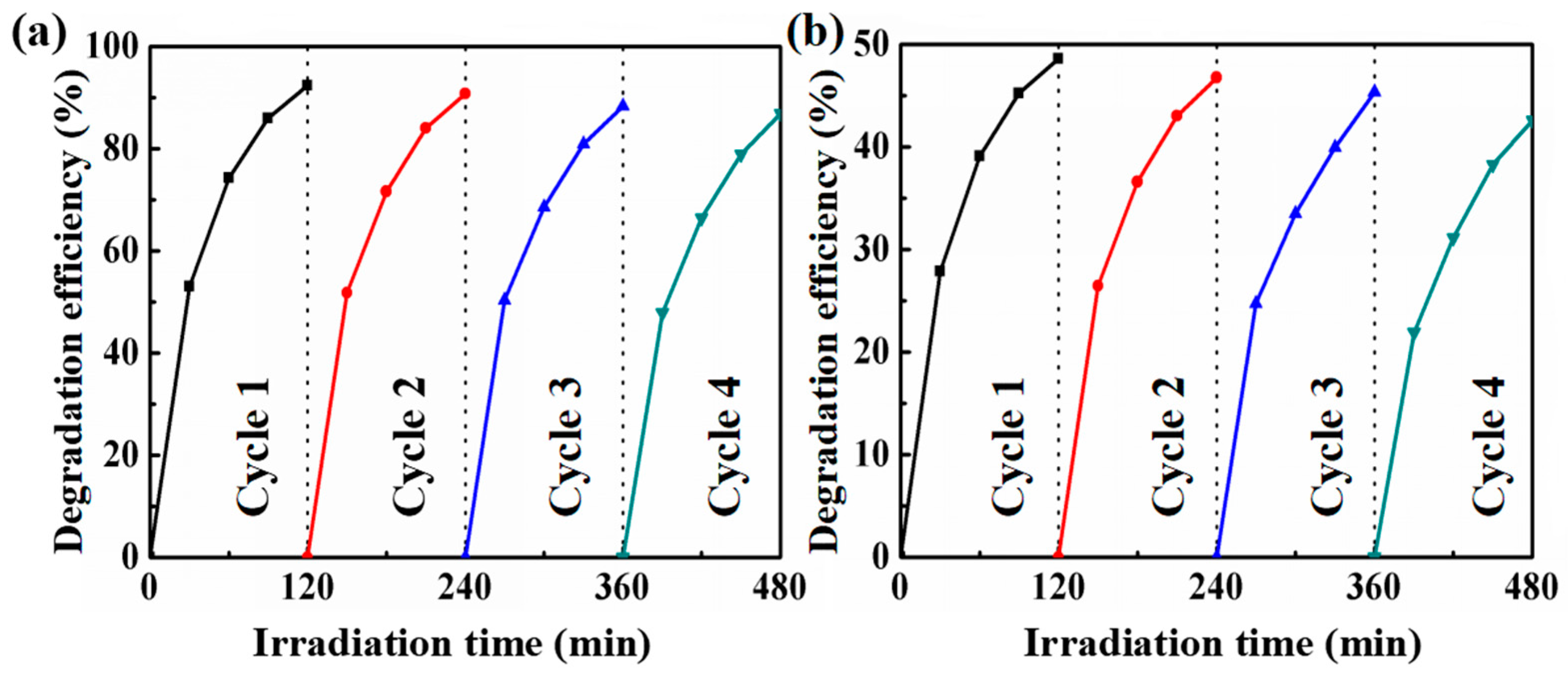
3.3. Photocatalytic Performance

The photocatalytic performance of the single ZnO NNs and ZnO@Cu2S NMSHs with different Cu2S QDs deposition amounts has been evaluated toward photocatalytic degradation of RhB under UV and visible light irradiation, respectively. As revealed in Figure 8a,b, the photolysis result of the blank sample which has been performed without photocatalyst is only about 3%, demonstrating that the dye solution is light stable in the absence of photocatalyst. Whether the experiment is done under UV or visible light, the ZnO@Cu2S NMSHs have higher photocatalytic degradation efficiency than the ZnO NNs during the entire photocatalytic degradation process (120 min). As the SILAR cycle time of Cu2S QDs increases from zero (S0) to two (S1), four (S2), or six (S3), the photocatalytic degradation efficiency performed under UV and visible light has been respectively increasing from 45.3% to 55.3%, 56.9%, and 92.3%, and increasing from 11.8% to 29.1%, 30.3%, and 48.6%, as the SILAR cycle time continues to increase to 8 (S4), the photocatalytic degradation efficiency performed under UV and visible light dose not continue to rise but decreased to 76% and 40%, respectively. Aforementioned results agree well with the color variations of the RhB solution before and after degradation (120 min) for S0–S4 samples as the photocatalysts under the irradiation of UV (the illustrations in Figure 8a) and visible (the illustrations in Figure 8b) light. The enhanced photocatalytic activity was contributed to the combination ZnO NNs with Cu2S QDs forming p-n heterojuctions and enhancing specific surface area. When increasing the loading amounts of Cu2S on the surface of ZnO NNs, the heterojunctions’ interface of Cu2S QDs and ZnO NNs, which can enhance the separation of the generated electron-hole pairs in the presence of light while avoids recombination, will increase at the same time. However, when an excessive amount of Cu2S QDs (SILAR cycle for eight times) was used, the more Cu2S QDs tended to aggregate together (Figure 3e), which could lead to the increased recombination of photoexcited charges. That is why the photocatalytic degradation efficiency increases first and then decreases. It can be seen that the degradation efficiency of the samples (S0–S4, under UV and visible light) never reached 100 percent, which is mainly ascribed to the existence of CuS phase that the information has been reflected in the XPS results (Figure 5d).
Photo-stability and reusability is also important for the practical application of photocatalysts. The durability of the ZnO@Cu2S NMSHs catalysts for the degradation of RhB under UV and visible illumination was investigated. Following a simple step of washing with water, the recycled photocatalyst was reused and the results of the photocatalyst degradation efficiency of RhB are shown in Figure 9a (UV light) and Figure 9b (visible light). It can be seen from Figure 9a,b that the degradation efficiency of the sample slightly declines after every cycle, probably due to the phase transformation of a little Cu2S to CuS [71]. Even so, the photodegradation efficiency of the S3 sample still does not exhibit a significant loss even after the fourth cycle, which indicates that the as-prepared ZnO@Cu2S NMSHs catalysts possesses an excellent photostability throughout the photocatalytic process.

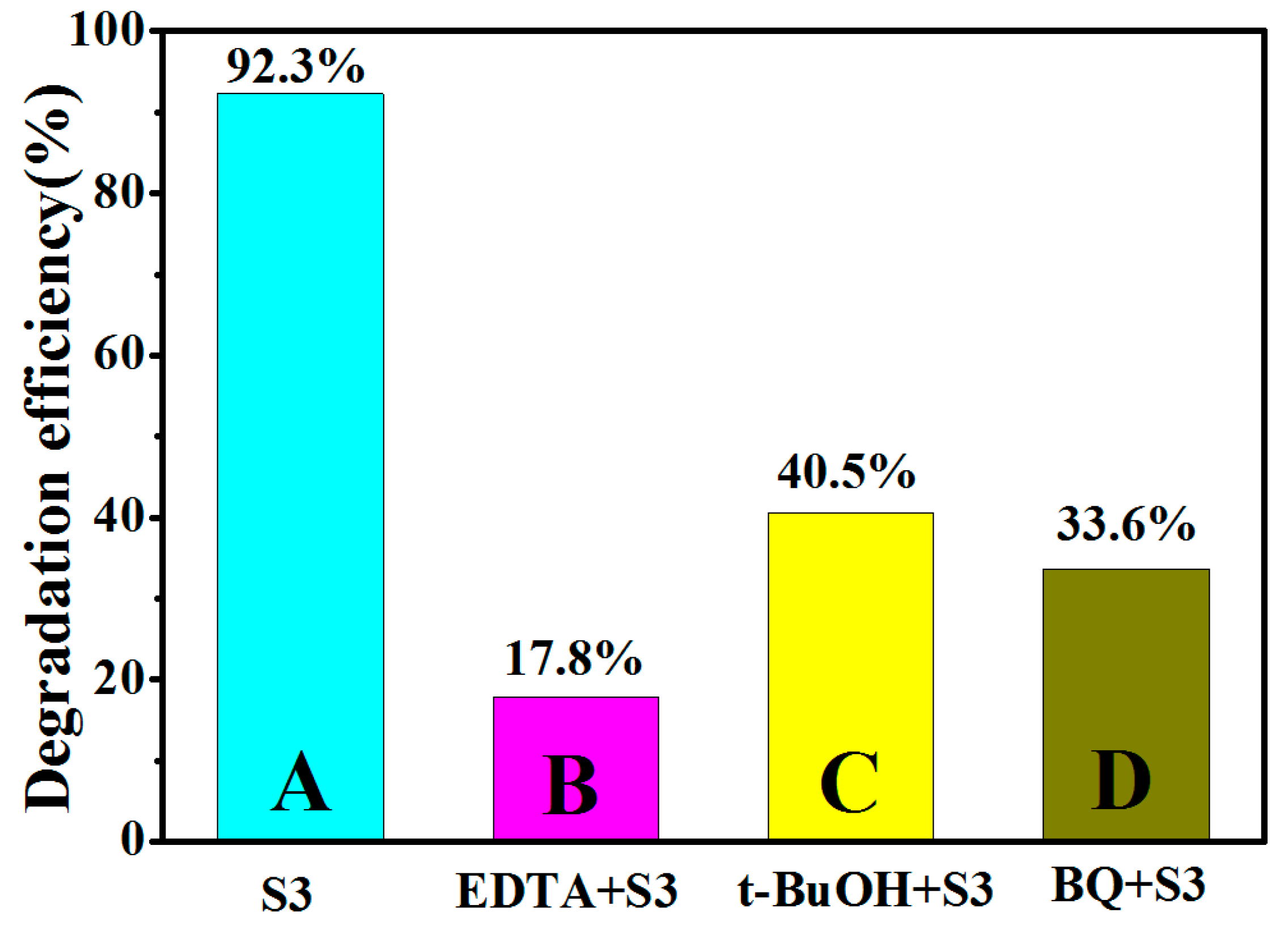
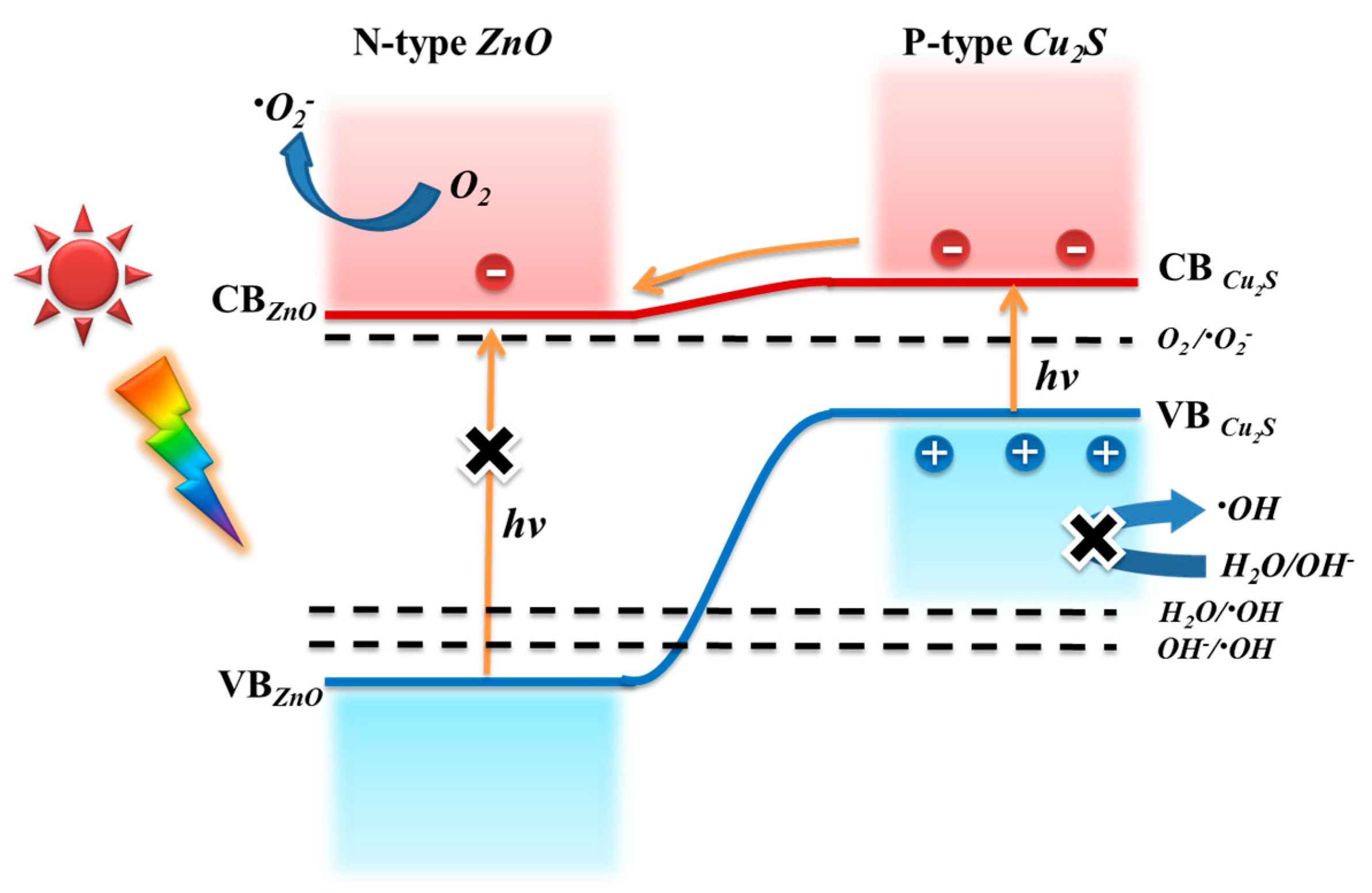
3.4. Photocatalytic Mechanism

According to the PL and UV-Vis results of S0–S4 samples, possible schematic diagram of the charge separation process in ZnO@Cu2S NMSHs are illustrated in Figure 10. Where the improved activity of the ZnO@Cu2S NMSHs under UV irradiation can be interpreted using two possible routes, as shown in Figure 10a,b. If the electron-hole pairs transfer following the heterojunction mechanism (Figure 10a), both the ZnO NNs and Cu2S QDs were excited to generate the electron-hole pairs. The photo-generated electrons are transferred from CB of Cu2S QDs into that of ZnO NNs, urging electrons to transfer to O2 to yield (superoxide anion radical) •O2. At the same time, the photo-induced holes are transferred from valence band (VB) of ZnO NNs into that of Cu2S QDs in heterojunction. However, holes were not adsorbed H2O or OH groups into (hydroxyl free radical) •OH, in virtue of the required potential for •OH generation is higher than the VB potential of Cu2S QDs [95,96,97,98]. If the photo-generated charges transfer was only carried out according to this process, then the active species that contribute to photocatalytic degradation will mainly consist of (photo-generated holes) h+ of Cu2S VB and •O2, •OH yield by •O2 will be just a little amount which can be ignored [99]. Meanwhile the photocatalytic efficiency should be very low, because •OH is well known to be very reactive oxidative species for the oxidation decomposition of organic molecules (RhB) or water pollutants and degrade them, which is inconsistent with the experiment results of Figure 8. Hence, the photo-induced electron-hole transfer in ZnO@Cu2S NMSHs may follow basically Z-scheme mechanism [100,101]. As expressed in Figure 10b, since the energy gap between CB of ZnO and VB of Cu2S is the smallest, the conduction band electrons of ZnO and the valence band holes of Cu2S are easy to recombine. And the photo-generated holes in ZnO remain mainly in its VB to transmit to H2O or OH to form highly reactive •OH, meanwhile the photo-generated electrons in the CB of Cu2S are trapped by O2 near the surface of Cu2S to form reactive •O2. Finally, the RhB is degraded by these highly active radical species. The photocatalytic reactions were possibly written as follows [71]:
ZnO/Cu2S + hγ → Cu2S (e + h+)/ZnO (e + h+) → Cu2S (e)/ZnO (h+)
e + O2 → •O2
h+ + OH → •OH
•O2 + H2O → •HO2 + OH
•HO2 + H2O → H2O2 + •OH
H2O2 → 2•OH
•OH + RhB → Oxidation products.
It is noteworthy that •OH is mainly derived from the redox reaction of h+, and just a little bit of •OH yield by •O2 which can be ignored in this photocatalytic reaction [99].
In order to further prove the basically Z-scheme mechanism under ultraviolet light, the scavenging experiment was performed. The scavenging experiment procedure is similar to the degradation experiment; various scavengers such as ethylene-diamine tetraacetate (EDTA), tert-butyl alcohol (t-BuOH), and 1,4-ben-zoquinone (BQ) were respectively introduced into the aqueous RhB before the addition of photocatalyst to scavenge the h+, •OH and •O2 [102,103]. As shown in Figure 11, the histogram from A to D shows the photodegradation efficiency results of scavenging experiment without adding any capture agent, adding h+ trapping agent EDTA, adding an •OH trapping agent t-BuOH, and adding an •O2 trapping agent BQ under UV light irradiation. After adding EDTA (capturing the h+), the photodegradation efficiency has dropped from 92.3% to 17.8% caused by the absence of the active species h+. Now the active species which is responsible for photocatalytic degradation efficiency is •O2. After adding t-BuOH (capturing the •OH), the active species are •O2 and h+, and the photodegradation efficiency is 40.5 % which is much higher than the result of B (17.8 %). After comparing this result with B, it can be inferred that the role of h+ in photocatalytic degradation of RhB is greater than that of •O2. Meanwhile, the •OH mainly originated from the oxidation of holes in the valence band of ZnO NNs is generated during catalytic degradation process because the photocatalytic efficiency is reduced after the •OH is captured. Hence, the conclusion that •OH converted from h+ and h+ participate jointly in photocatalytic degradation in this process can be obtained, which is consistent with the basically Z-scheme mechanism in Figure 10b. After adding BQ (capturing the •O2), the photodegradation efficiency is 33.6 %, and the active species which is responsible for photocatalytic degradation efficiency are h+ and •OH generated by h+, which proves the existence of h+ and •OH generated by h+ once again, and further proves that the electronic transmission mechanism is the Z-scheme mechanism.
Figure 12 depicts electron-transfer processes of ZnO@Cu2S NMSHs under visible light illumination. When visible light is irradiated on ZnO@Cu2S NMSHs, only the ground state electronics of Cu2S QDs can absorb solar energy and jump to the conduction band, and ZnO NNs can’t, due to its wider band gap (3.37 eV). After exposure to visible light, the holes keep remain in the Cu2S QDs valence band and the conduction band (CB) electrons of Cu2S QDs transfer to the conduction band of ZnO NNs by electron injection, which helps in the separation of the photo-generated electron-hole pairs and avoids recombination. The electronics in conduction band of ZnO NNs reacted with the dissolved oxygen on ZnO surface to yield the •O2 which can continuously participated in the photocatalytic reaction to generate the •HO2 and •OH. However, the accumulated photo-generated holes in the valence band (VB) of Cu2S QDs can’t react with adsorbed H2O or OH to form •OH radicals, because the valence band potential of Cu2S QDs is lower than the •OH. It is possible that the holes themselves directly oxidize the RhB molecules [95,104]. The analysis of above investigation about charge separation process in ZnO@Cu2S NMSHs under UV and visible light is consistent with the result of photocatalytic degradation experiments, namely, h+ and •O2 are main active species under visible light illumination, except for the highly reactive •OH. Therefore, it is easy to understand that the photocatalytic activity under UV light is much higher than the photocatalytic activity under visible light for the same samples.
In the last decade, enormous efforts have been made to prepare different photocatalysts, for example Ag3PO4/ZnO [105,106], ZnO/CuO [107,108], ZnO@AgI [109,110], TiO2/g-C3N4 [111], MoS2@Cu2S [112], and so on, for degrading various organic dyes, such as methyl orange (MO) [112,113,114], RhB [105,106,107,108,115], methylene blue (MB) [116,117], phenol [118], etc. It can be seen from Table 1 that even if the components constituting the heterojunction photocatalyst are the same, the photocatalytic degradation efficiency is not the same due to the different conditions in experimental, such as, the amount of catalyst, the type and concentration of organic dyes, and the source used in photocatalytic degradation experiments, the distance between the sample and the source, and the exposure time. The photocatalytic degradation efficiency of the same organic dye is not the same because of the different photocatalysts or experiment conditions used. Thus extensive possibilities exist in this promising area of research, which need to be given full attention and the achievements of such exploration should benefit commercial sector both in terms of ecology and economy.

4. Conclusions

In this work, a novel nano-match-shaped ZnO@Cu2S photocatalyst with a p-n heterostructure was successfully synthesized. The amount of Cu2S QDs in ZnO@Cu2S NMSHs, which can be controlled by adjusting the number of SILAR cycles, was the key factor for the photocatalytic performance of the fabricated samples. As the SILAR cycle time of Cu2S QDs increases, the photocatalytic performances increases first and then decreases no matter what light sources were used. The enhanced photocatalytic activity was contributed to the combination ZnO NNs with Cu2S QDs forming p–n heterojuctions and the declined photocatalytic activity was attributed to the more Cu2S QDs tended to aggregate together. It is worth noting that the photocatalytic performance of the same sample irradiated with UV light is much higher than that of visible light. This is because the charge transport of the sample under the illumination of the UV light follows the Z-scheme mechanism, so not only h+ and •O2 active species but also the highly reactive •OH will be yielded, however, the ZnO in the sample could not be excited to generate electronic-hole pairs while the sample exposed to visible light, so only h+ and •O2 active species can be produced without the highly reactive •OH. In addition, the photocatalytic efficiency of the S3 sample has no significant decrease even after four cycles, which indicates that the ZnO@Cu2S NMSHs photocatalyst exhibits an excellent stability throughout the photocatalytic process. It is believed that the study of the composite materials with p–n heterostructure for high-efficiency photocatalytic applications will contribute to the development of energy conservation and environmental protection.

Author Contributions

Contributor Roles Taxonomy (CRediT): Conceptualization, D.H.; Investigation, B.L.; Writing—Original Draft Preparation, D.H.; Writing—Review & Editing, D.W.; Characterization test, S.Y., X.W., W.G., Z.S., Q.Z., Y.L. (Yanhui Li), and Y.L. (Yanwei Li); Funding Acquisition, D.H. and Q.D.

Funding

This research was funded by the National Youth Program Foundation of China: 61705020, 61705079, 51609100, 61605059, 61505067, the National Natural Science Foundation of China: 61475063, 21676115, Program for the development of Science and Technology of Jilin province: 20190103002JH, 20180519016JH, 20180414008GH, the Thirteenth Five-Year Program for Science and Technology of Education Department of Jilin Province: JJKH20190550KJ.

Conflicts of Interest

The authors declare no conflict of interest.

References

  1. Yang, J.H.; Wang, J.; Li, X.Y.; Wang, D.D.; Song, H. Synthesis of urchin-like Fe3O4@SiO2@ZnO/CdS core-shell microspheres for the repeated photocatalytic degradation of rhodamine B under visible light. Catal. Sci. Technol. 2016, 6, 4525–4534. [Google Scholar] [CrossRef]
  2. Enesca, A.; Isac, L.; Duta, A. Hybrid structure comprised of SnO2, ZnO and Cu2S thin film semiconductors with controlled optoelectric and photocatalytic properties. Thin Solid Films 2013, 542, 31–37. [Google Scholar] [CrossRef]
  3. Chen, W.; Zhang, N.; Zhang, M.Y.; Zhang, X.T.; Gao, H.; Wen, J. Controllable growth of ZnO-ZnSe heterostructures for visible-light photocatalysis. CrystEngComm 2014, 16, 1201–1206. [Google Scholar] [CrossRef]
  4. Chen, L.; Zhang, W.X.; Feng, C.; Yang, Z.H.; Yang, Y.M. Replacement/etching route to ZnSe nanotube arrays and their enhanced photocatalytic activities. Ind. Eng. Chem. Res. 2012, 51, 4208–4214. [Google Scholar] [CrossRef]
  5. Xiang, C.M.; Ying, D.; Lin, Y.; Bai, B.H. Energy transfer in plasmonic photocatalytic composites. Light Sci. Appl. 2016, 5, e16017. [Google Scholar]
  6. Savitskii, D.P.; Stanishevskii, Y.M. Growing Cu2S Thin Films by Exposing a Copper Substrate to Gas-Phase Products of Brown Coal Hydrothermal Desulfurization. Russ. Phys. Chem. A 2018, 92, 147–154. [Google Scholar] [CrossRef]
  7. Francesca, P.; Katsuhiro, I.; Kazushi, M. A visible light-driven plasmonic photocatalyst. Light Sci. Appl. 2014, 3, e133. [Google Scholar]
  8. Shanshan, C.; Tsuyoshi, T.; Kazunari, D. Particulate photocatalysts for overall water splitting. Nat. Rev. Mater. 2017, 2, 17050. [Google Scholar]
  9. Low, J.; Yu, J.; Jaroniec, M.; Wageh, S.; Al-Ghamdi, A.A. Heterojunction Photocatalysts. Adv. Mater. 2017, 29, 1601694. [Google Scholar] [CrossRef] [Green Version]
  10. Matías, E.A.; Zhou, R.; Eugene, A.J. Cu2O/TiO2 heterostructures for CO2 reduction through a direct Z-scheme: Protecting Cu2O from photocorrosion. Appl. Catal. B Environ. 2017, 217, 485–493. [Google Scholar]
  11. Jamadi, O.; Reveret, F.; Disseix, P.; Medard, F.; Leymarie, J.; Moreau, A.; Solnyshkov, D.; Deparis, C.; Leroux, M.; Cambril, E.; et al. Edge-emitting polariton laser and amplifier based on a ZnO waveguide. Light Sci. Appl. 2018, 7, 82. [Google Scholar] [CrossRef] [PubMed]
  12. Li, S.C.; Yu, K.; Wang, Y.; Zhang, Z.L.; Song, C.Q.; Yin, H.H.; Ren, Q.; Zhu, Z.Q. Cu2S@ZnO hetero-nanostructures: Facile synthesis, morphology-evolution and enhanced photocatalysis and field emission properties. CrystEngComm 2013, 15, 1753–1761. [Google Scholar] [CrossRef]
  13. Lan, L.; Xia, Y.; Li, R.; Liu, K.; Mai, J.; Medley, J.A.; Obeng-Gyasi, S.; Han, L.K.; Wang, P.; Cheng, J.X. A fiber optoacoustic guide with augmented reality for precision breast-conserving surgery. Light Sci. Appl. 2018, 7, 2. [Google Scholar] [CrossRef]
  14. Gu, C.D.; Cheng, C.; Huang, H.Y.; Wong, T.L.; Wang, N.; Zhang, T.Y. Growth and photocatalytic activity of dendrite-like ZnO@Ag heterostructure nanocrystals. Cryst. Growth Des. 2009, 9, 3278–3285. [Google Scholar] [CrossRef]
  15. Pawan, K.S.; Young, T.C.; Daping, C. A high-resolution optically addressed spatial light modulator based on ZnO nanoparticles. Light Sci. Appl. 2015, 4, e259. [Google Scholar]
  16. Xing, G.Z.; Fang, X.S.; Zhang, Z. Ultrathin single-crystal ZnO nanobelts: Ag-catalyzed growth and field emission property. Nanotechnology 2010, 21, 255701. [Google Scholar] [CrossRef] [PubMed]
  17. Wang, D.D.; Xing, G.Z.; Yan, F.; Yan, Y.S.; Li, S. Ferromagnetic (Mn, N)-codoped ZnO nanopillars array: Experimental and computational insights. Appl. Phys. Lett. 2014, 104, 022412. [Google Scholar] [CrossRef]
  18. Wang, D.D.; Chen, Q.; Xing, G.G. Robust Room-Temperature Ferromagnetism with Giant Anisotropy in Nd-Doped ZnO Nanowire Arrays. Nano Lett. 2012, 12, 3994. [Google Scholar] [CrossRef]
  19. Xing, G.Z.; Xing, G.C.; Li, M.J. Charge transfer dynamics in Cu-doped ZnO nanowires. Appl. Phys. Lett. 2011, 98, 102105. [Google Scholar] [CrossRef]
  20. Georgiev, P.; Kaneva, N.; Bojinova, A.; Papazova, K.; Mircheva, K.; Balashev, K. Effect of gold nanoparticles on the photocatalytic efficiencyof ZnO films. Colloid Surf. A 2014, 460, 240–247. [Google Scholar] [CrossRef]
  21. Ranjith, K.S.; Senthamizhan, A.; Balusamya, B.; Uyar, T. Nanograined surface shell wall controlled ZnO-ZnS core-shell nanofibers and their shell wall thickness dependent visible photocatalytic properties. Catal. Sci. Technol. 2017, 7, 1167–1180. [Google Scholar] [CrossRef]
  22. Mostoni, S.; Pifferi, V.; Falciola, L.; Meroni, D.; Pargoletti, E.; Davoli, E.; Cappelletti, G. Tailored routes for home-made Bi-doped ZnO nanoparticles. Photocatalytic performances towards o-toluidine, a toxic water pollutant. J. Photochem. Photobiol. A 2017, 332, 534–545. [Google Scholar] [CrossRef]
  23. Demille, T.B.; Hughes, R.A.; Preston, A.S.; Adelung, R.; Mishra, Y.K.; Neretina, S. Light-Mediated Growth of Noble Metal Nanostructures (Au, Ag, Cu, Pt, Pd, Ru, Ir, Rh) From Micro- and Nanoscale ZnO Tetrapodal Backbones. Front. Chem. 2018, 6, 411. [Google Scholar] [CrossRef] [PubMed]
  24. Pal, M.; Bera, S.; Sarkar, S.; Jana, S. Influence of Al doping on microstructural, optical and photocatalytic properties of sol–gel based nanostructured zinc oxide films on glass. RSC Adv. 2014, 4, 11552–11563. [Google Scholar] [CrossRef]
  25. Zhou, Z.; Toshitaka, K.; Masahito, Y. Enhanced 1.54 μm photoluminescence from Er-containing ZnO through nitrogen doping. Appl. Phys. Lett. 2005, 86, 1979. [Google Scholar] [CrossRef]
  26. Chao, X.; Peng, Y.; Zhike, L.; Li, L.; Feng, Y. Ultrasensitive broadband phototransistors based on perovskite/organic-semiconductor vertical heterojunctions. Light Sci. Appl. 2017, 6, e17023. [Google Scholar]
  27. Tanaka, A.; Teramura, K.; Hosokawa, S.; Kominami, H.; Tanaka, T. Visible light-induced water splitting in an aqueous suspension of a plasmonic Au/TiO2 photocatalyst with metal co-catalysts. Chem. Sci. 2017, 8, 2574–2580. [Google Scholar] [CrossRef]
  28. Leilei, G.; Zhiyong, F. Perovskite/organic-semiconductor heterojunctions for ultrasensitive photodetection. Light Sci. Appl. 2017, 6, e17090. [Google Scholar]
  29. Chen, Y.H.; Ma, D.G.; Sun, H.D.; Chen, J.S.; Guo, Q.X.; Wang, Q.; Zhao, Y.B. Organic semiconductor heterojunctions: Electrode-independent charge injectors for high-performance organic light-emitting diodes. Light Sci. Appl. 2016, 5, e16042. [Google Scholar] [CrossRef]
  30. Hoque, M.A.; Guzman, M.I. Photocatalytic Activity: Experimental Features to Report in Heterogeneous Photocatalysis. Materials 2018, 11, 1990. [Google Scholar] [CrossRef]
  31. Meenal, D.; Deodatta, S.; Ashish, Y.; Jyoti, J.; Beatrice, H. Cu2O/ZnO hetero-nanobrush: Hierarchical assembly, field emission and photocatalytic properties. J. Mater. Chem. 2012, 22, 17055. [Google Scholar]
  32. Luo, Q.; Wu, Z.M.; He, J.L.; Cao, Y.Y.; Bhutto, W.A.; Wang, W.P.; Zheng, X.L.; Kang, J.Y. Facile synthesis of composition-tuned ZnO/ZnxCd1-xSe nanowires for photovoltaic applications. Nanoscale Res. Lett. 2015, 10, 181. [Google Scholar] [CrossRef] [PubMed]
  33. Salehi, M.M.; Saboori, R.; Sabbaghi, S. Hydrogen sulfide removal in water-based drilling fluid by metal oxide nanoparticle and ZnO/TiO2 nanocomposite. Mater. Res. Express 2017, 4, 075501. [Google Scholar] [CrossRef]
  34. Zhou, R.; Guzman, M.I. CO2 Reduction under Periodic Illumination of ZnS. J. Phys. Chem. C 2014, 118, 118–11656. [Google Scholar] [CrossRef]
  35. Zhou, R.; Guzman, M.I. Photocatalytic Reduction of Fumarate to Succinate on ZnS Mineral Surfaces. J. Phys. Chem. C 2016, 120, 7349–7357. [Google Scholar] [CrossRef]
  36. Mishra, Y.K.; Adelung, R. ZnO tetrapod materials for functional applications. Mater. Today 2018, 21, 631–651. [Google Scholar] [CrossRef]
  37. Jorit, G.; Fabian, S.; Daria, S.; Oleg, L.; Rainer, A.; Yogendra, K.M. Porous ceramics based on hybrid inorganic tetrapodal networks for efficient photocatalysis and water purification. Ceram. Int. 2017, 43, 14915–14922. [Google Scholar]
  38. Liu, W.; Hao, J.; Xu, C.; Mou, J.; Dong, L.; Jiang, F.; Kang, Z.; Wu, J.; Jiang, B.; Kang, F. Investigation of zinc ion storage of transition metal oxides, sulfides, and borides in zinc ion battery systems. Chem. Commun. 2017, 53, 6872–6874. [Google Scholar] [CrossRef]
  39. Di Credico, B.; Bellobono, I.R.; D’Arienzo, M.; Fumagalli, D.; Redaelli, M.; Scotti, R.; Morazzoni, F. Efficacy of the Reactive Oxygen Species Generated by Immobilized TiO2 in the Photocatalytic Degradation of Diclofenac. Int. J. Photoenergy 2015, 2015, 919217. [Google Scholar] [CrossRef]
  40. Di Credico, B.; Redaelli, M.; Bellardita, M.; Calamante, M.; Cepek, C.; Cobani, E.; D’Arienzo, M.; Evangelisti, C.; Marelli, M.; Moret, M.; et al. Step-by-Step Growth of HKUST-1 on Functionalized TiO2 Surface: An Efficient Material for CO2 Capture and Solar Photoreduction. Catalysts 2018, 8, 353. [Google Scholar] [CrossRef]
  41. Li, B.X.; Wang, Y.F. Facile synthesis and photocatalytic activity of ZnO/CuO nanocomposite. Superlattice. Microstruct. 2010, 47, 615–623. [Google Scholar] [CrossRef]
  42. Arai, T.; Yanagida, M.; Konishi, Y.; Iwasaki, Y.; Sayama, K. Efficient complete oxidation of acetaldehyde into CO2 over CuBi2O4/WO3 composite photocatalyst under visible and UV light irradiation. J. Phys. Chem. C 2007, 111, 7574–7577. [Google Scholar] [CrossRef]
  43. Li, Y.; Wang, W.N.; Zhan, Z. Photocatalytic reduction of CO2 with H2O on mesoporous silica supported Cu/TiO2 catalysts. Appl. Catal. B Environ. 2010, 100, 386–392. [Google Scholar] [CrossRef]
  44. Zhao, B.; Li, S.C.; Zhang, Q.F.; Wang, Y.; Song, C.Q.; Zhang, Z.L.; Yu, K.; Xu, J.; Li, Y.; Peng, S. Controlled synthesis of Cu2S microrings and their photocatalytic and field emission properties. Chem. Eng. J. 2013, 230, 236–243. [Google Scholar] [CrossRef]
  45. Xu, J.; Li, Y.; Peng, S. Photocatalytic hydrogen evolution over Erythrosin B-sensitized graphitic carbon nitride with in situ grown molybdenum sulfide cocatalyst. Int. J. Hydrogen Energy 2015, 40, 353. [Google Scholar] [CrossRef]
  46. Meng, F.; Li, J.; Cushing, S.K.; Zhi, M.; Wu, N. Solar Hydrogen Generation by Nanoscale p-n Junction of p-type Molybdenum Disulfide/n-type Nitrogen-Doped Reduced Graphene Oxide. J. Am. Chem. Soc. 2013, 135, 10286. [Google Scholar] [CrossRef]
  47. Su, Z.; Li, H.; Chen, P.; Hu, S.; Yan, Y. Novel heterostructured InN/TiO2 submicron fibers designed for high performance visible-light-driven photocatalysis. Catal. Sci. Technol. 2017, 7, 5105–5112. [Google Scholar]
  48. Nayak, A.; Ohno, T.; Tsuruoka, T.; Terabe, K.; Hasegawa, T.; Gimzewski, J.K.; Aono, M. Controlling the Synaptic Plasticity of a Cu2S Gap-Type Atomic Switch. Adv. Funct. Mater. 2012, 22, 3606–3613. [Google Scholar] [CrossRef]
  49. Riha, S.C.; Jin, S.; Baryshev, S.V.; Thimsen, E.; Wiederrecht, G.P.; Martinson, A.B.F. Stabilizing Cu2S for Photovoltaics One Atomic Layer at a Time. ACS Appl. Mater. Interfaces 2013, 5, 10302–10309. [Google Scholar] [CrossRef]
  50. Zhuang, T.T.; Fan, F.J.; Gong, M.; Yu, S.H. Cu1.94S nanocrystal seed mediated solution-phase growth of unique Cu2S-PbS heteronanostructures. Chem. Commun. 2012, 48, 9762–9764. [Google Scholar] [CrossRef]
  51. Pan, Z.X.; Zhao, K.; Wang, J.; Zhang, H.; Feng, Y.Y.; Zhong, X.H. Near Infrared Absorption of CdSexTe1-x Alloyed Quantum Dot Sensitized Solar Cells with More than 6% Efficiency and High Stability. ACS Nano 2013, 7, 5215–5222. [Google Scholar] [CrossRef] [PubMed]
  52. Peng, M.; Ma, L.L.; Zhang, Y.G.; Tan, M.; Wang, J.B.; Yu, Y. Controllable synthesis of self-assembled Cu2S nanostructures through a template-free polyol process for the degradation of organic pollutant under visible light. Mater. Res. Bull. 2009, 44, 1834–1841. [Google Scholar] [CrossRef]
  53. Zhang, P.; Honga, R.Y.; Chen, Q.; Feng, W.G. On the electrical conductivity and photocatalytic activity of aluminium-doped zinc oxide. Powder Technol. 2014, 253, 360–367. [Google Scholar] [CrossRef]
  54. D’Arienzo, M.; Redaelli, M.; Di Credico, B.; Polizzi, S.; Scotti, R.; Morazzoni, F. New insights into the sensing mechanism of shape controlled ZnO particles. RSC Adv. 2016, 6, 52987–52997. [Google Scholar] [CrossRef]
  55. Ivanovaa, T.; Harizanovaa, A.; Koutzarovab, T.; Vertruyenc, B. Study of ZnO sol–gel films: Effect of annealing. Mater. Lett. 2010, 64, 1147–1149. [Google Scholar] [CrossRef]
  56. Kołodziejczak, R.A.; Jesionowski, T. Zinc Oxide—From Synthesis to Application: A Review. Materials 2014, 7, 2833. [Google Scholar] [CrossRef] [PubMed]
  57. Ahmad, M.; Ahmed, E.; Zhang, Y.; Khalid, N.R.; Xu, J.; Ullah, M.; Hong, Z. Preparation of highly efficient Al-doped ZnO photocatalyst by combustion synthesis. Curr. Appl. Phys. 2013, 13, 697–704. [Google Scholar] [CrossRef]
  58. Shinde, S.D.; Date, S.K.; Deshmukh, A.V.; Das, A.P.; Kukreja, L.M.; Adhi, K.P. Role of Al doping in structural, microstructural, electrical and optical characteristics of as deposited and annealed ZnO thin films. RSC Adv. 2015, 5, 24178–24187. [Google Scholar] [CrossRef]
  59. Hsiao, K.C.; Liao, S.C.; Chen, Y.J. Synthesis, characterization and photocatalytic property of nanostructured Al-doped ZnO powders prepared by spray pyrolysis. Mater. Sci. Eng. A 2007, 447, 71–76. [Google Scholar] [CrossRef]
  60. Zhuge, F.; Li, X.; Gao, X. Synthesis of stable amorphous Cu2S thin film by successive ion layer adsorption and reaction method. Mater. Lett. 2009, 63, 652–654. [Google Scholar] [CrossRef]
  61. Siol, S.; Sträter, H.; Brüggemann, R. PVD of copper sulfide (Cu2S) for PIN-structured solar cells. J. Phy. D Appl. Phys. 2013, 46, 5112. [Google Scholar] [CrossRef]
  62. Salavati-Niasari, M.; Alizadeh, S.; Mousavi-Kamazani, M. Surfactant-Free Fabrication of Copper Sulfides (CuS, Cu2S) via Hydrothermal Method. J. Clust. Sci. 2013, 24, 1181–1191. [Google Scholar] [CrossRef]
  63. Maji, S.K.; Dutta, A.K.; Bhadu, G.R. A novel amperometric biosensor for hydrogen peroxide and glucose based on cuprous sulfide nanoplates. J. Mater. Chem. B 2013, 1, 4127. [Google Scholar] [CrossRef]
  64. Cao, J.; Han, D.L.; Wang, B.J. Low temperature synthesis, photoluminescence, magnetic properties of the transition metal doped wurtzite ZnS nanowires. J. Solid State Chem. 2013, 200, 317–322. [Google Scholar] [CrossRef]
  65. Qu, D.; Zheng, M.; Li, J.; Xie, Z.G.; Sun, Z.C. Tailoring color emissions from N-doped graphene quantum dots for bioimaging applications. Light Sci. Appl. 2015, 4, e364. [Google Scholar] [CrossRef]
  66. Luo, X.; Tseng, L.T.; Lee, W.T.; Xing, G.Z.; Tao, L.; Sean, L.; Yi, J.B. Monodispersed ZnO Quantum Dots with Nd Doping. Nanosci. Nanotechnol. Lett. 2015, 7, 417. [Google Scholar] [CrossRef]
  67. Silke, L.D.; Dominik, K.; Tania, L.; Gerasimos, K. Integrated colloidal quantum dot photodetectors with color-tunable plasmonic nanofocusing lenses. Light Sci. Appl. 2015, 4, e234. [Google Scholar]
  68. Wang, L.; Li, Q.; Wang, H.Y.; Huang, J.C.; Zhang, R.; Chen, Q.D.; Xu, H.L.; Han, W.; Shao, Z.Z.; Sun, H.B. Ultrafast optical spectroscopy of surface-modified silicon quantum dots: Unraveling the underlying mechanism of the ultrabright and color-tunable photoluminescence. Light Sci. Appl. 2015, 4, e245. [Google Scholar] [CrossRef]
  69. Suresh, K.V.; Ealisha, J.; Pritam, K.P.; Jugal, K.D.; Mrutyunjay, S. Molecular aspects of core-shell intrinsic defect induced enhanced antibacterial activity of ZnO nanocrystals. Nanomedicine 2018, 13, 43–68. [Google Scholar]
  70. Wang, S.; Kuang, P.; Cheng, B. ZnO hierarchical microsphere for enhanced photocatalytic activity. J. Alloy Compd. 2018, 741, 622–632. [Google Scholar] [CrossRef]
  71. De-Zhi, W.U.; Fan, X.M.; Tian, K. Fabrication and photocatalytic properties of Cu2S/T-ZnO w heterostructures via simple polyol process. Trans. Nonferr. Metals Soc. 2012, 22, 1620–1628. [Google Scholar]
  72. Han, D.; Cao, J.; Yang, S. Investigation of composition dependent structural and optical properties of the Zn(1−x)Cd(x)S., coaxial Zn(0.99−x)Cd(x)Cu(0.01)S/ZnS, Zn(0.99−x)Cd(x)Mn(0.01)S nanorods generated by a one-step hydrothermal process. Dalton Trans. 2014, 43, 11019–11026. [Google Scholar] [CrossRef]
  73. Zhang, X.; Wang, Y.; Hou, F. Effects of Ag loading on structural and photocatalytic properties of flower-like ZnO microspheres. Appl. Surf. Sci. 2017, 391, 476–483. [Google Scholar] [CrossRef]
  74. Kamarulzaman, N.; Kasim, M.F.; Chayed, N.F. Elucidation of the highest valence band and lowest conduction band shifts using XPS for ZnO and Zn0.99Cu0.01O band gap changes. Res. Phys. 2016, 6, 217–230. [Google Scholar]
  75. Hsieh, P.T.; Chen, Y.C.; Kao, K.S. Luminescence mechanism of ZnO thin film investigated by XPS measurement. Appl. Phys. A 2008, 90, 317–321. [Google Scholar] [CrossRef]
  76. Lu, Y.J.; Jia, J.H. The effect of complexing agent on crystal growth, structure and properties of nanostructured Cu2-xS thin films. Chin. Chem. Lett. 2014, 25, 1473–1478. [Google Scholar] [CrossRef]
  77. Xue, H.; Chen, Y.; Xu, X.L.; Zhang, G.H.; Zhang, H.; Ma, S.Y. X-ray diffraction spectroscopy and X-ray photoelectron spectroscopy studies of Cu-doped ZnO films. Phys. E 2009, 41, 788–791. [Google Scholar] [CrossRef]
  78. Biesinger, M.C.; Payne, B.P.; Hart, B.R.; Grosvenor, A.P.; McIntryre, N.S.; Lau, L.W.M. Quantitative chemical state XPS analysis of first row transition metals, oxidesand hydroxides. J. Phys. 2008, 100, 012025. [Google Scholar]
  79. Svintsitskiy, D.A.; Chupakhin, A.P.; Slavinskaya, E.M. Study of cupric oxide nanopowders as efficient catalysts for low-temperature CO oxidation. J. Mol. Catal. A Chem. 2013, 368, 95–106. [Google Scholar] [CrossRef]
  80. Van der Heide, P.A.W. Multiplet splitting patterns exhibited by the first row transition metal oxides in X-ray photoelectron spectroscopy. J. Electron. Spectrosc. 2008, 164, 8–18. [Google Scholar] [CrossRef]
  81. Poulose, A.C.; Veeranarayanan, S.; Mohamed, M.S. Multi-Stimuli Responsive Cu2S Nanocrystals as Trimodal Imaging and Synergistic Chemo-Photothermal Therapy Agents. Nanoscale 2015, 7, 8378–8388. [Google Scholar] [CrossRef] [PubMed]
  82. Xu, F.; Yuan, Y.; Han, H.; Wu, D.; Gao, Z.; Jiang, K. Synthesis of ZnO/CdS hierarchical heterostructure with enhanced photocatalytic efficiency under nature sunlight. CrystEngComm 2012, 14, 3615–3622. [Google Scholar] [CrossRef]
  83. Yunhee, K.; Kee, Y.P.; Dong, M.J.; Yun, M.S.; Han, S.K.; Yong, J.C.; Yoon, M.; Jeunghee, P. Synthesis of Au-Cu2S Core-Shell Nanocrystals and Their Photocatalytic and Electrocatalytic Activity. J. Phys. Chem. C 2010, 114, 22141–22146. [Google Scholar]
  84. Guo, K.; Chen, X.; Han, J. Synthesis of ZnO/Cu2S core/shell nanorods and their enhanced photoelectric performance. J. Sol-Gel Sci. Technol. 2014, 72, 92–99. [Google Scholar] [CrossRef]
  85. Monreal, R.C.; Apell, S.P.; Antosiewicz, T. Quantum-Size Effects in Visible Defect Photoluminescence of Colloidal ZnO Quantum Dots: A Theoretical Analysis. Nanoscale 2018, 10, 7016–7025. [Google Scholar] [CrossRef] [PubMed]
  86. Dakhlaoui, H.B.B.; Mouna, N. Quantum Size and Magnesium Composition Effects on the Optical Absorption in the MgxZn(1−x)O/ZnO Quantum Well. Chem. Phys. Lett. 2018, 693, 40–45. [Google Scholar] [CrossRef]
  87. Susanna, A.; Armelao, L.; Callone, E. ZnO nanoparticles anchored to silica filler. A curing accelerator for isoprene rubber composites. Chem. Eng. J. 2015, 275, 245–252. [Google Scholar] [CrossRef]
  88. Liang, Y.; Wicker, S.; Wang, X. Organozinc Precursor-Derived Crystalline ZnO Nanoparticles: Synthesis, Characterization and Their Spectroscopic Properties. Nanomaterials 2018, 8, 22. [Google Scholar] [CrossRef]
  89. Yang, J.H.; Kong, X.W.; Jiang, W.L.; Cao, J.; Zou, P.; Luan, H.M.; Yang, L.L. Size-controllable synthesis and photocatalytic performance of ZnO hollow spheres. Mat. Sci. Semicon. Proc. 2015, 40, 713–719. [Google Scholar] [CrossRef]
  90. Tang, Q.; Zhou, W.J.; Shen, J.M.; Zhang, W.; Kong, L.F.; Qian, Y.T. A template-free aqueous route to ZnO nanorod arrays with high optical property. Chem. Comm. 2004, 6, 712–713. [Google Scholar] [CrossRef]
  91. Stavale, F.; Nilius, N.; Freund, H.-J. STM Luminescence Spectroscopy of Intrinsic Defects in ZnO(0001) Thin Films. J. Phys. Chem. Lett. 2013, 4, 3972–3976. [Google Scholar] [CrossRef]
  92. Kohan, A.F.; Ceder, G.; Morgan, D.; Van de Walle, C.G. First-Principles Study of Native Point Defects in ZnO. Phys. Rev. B 2000, 61, 15019. [Google Scholar] [CrossRef]
  93. Chen, Y.B.; Qin, Z.X.; Wang, X.X.; Guo, X.; Guo, L.J. Noble-metal-free Cu2S-modified photocatalysts for enhanced photocatalytic hydrogen production by forming nanoscale p-n junction structure. RSC Adv. 2015, 5, 18159. [Google Scholar] [CrossRef]
  94. Riha, S.C.; Schaller, R.D.; Gosztola, D.J. Photoexcited Carrier Dynamics of Cu2S Thin Films. J. Phys. Chem. Lett. 2015, 5, 4055–4061. [Google Scholar] [CrossRef] [PubMed]
  95. Yan, S.; Rai, S.C.; Zheng, Z. Piezophototronic Effect Enhanced UV/Visible Photodetector Based on ZnO/ZnSe Heterostructure Core/Shell Nanowire Array and Its Self-Powered Performance. Adv. Electron. Mater. 2016, 2, 1600242. [Google Scholar] [CrossRef]
  96. Bian, F.; Hong, K.Q.; Ge, X.; Song, R.; Liu, L.Q.; Xu, M.X. Functional hierarchical nanocomposites based on ZnO nanowire and magnetic nanoparticle as highly active recyclable photocatalysts. J. Phys. Chem. C 2015, 119, 1700–1705. [Google Scholar] [CrossRef]
  97. Wang, J.; Fan, X.M.; Wu, D.Z. Fabrication of CuO/T-ZnOw nanocomposites using photo-deposition and their photocatalytic property. Appl. Surf. Sci. 2011, 258, 1797–1805. [Google Scholar] [CrossRef]
  98. Wei, S.; Chen, Y.; Ma, Y. Fabrication of CuO/ZnO composite films with cathodic co-electrodeposition and their photocatalytic performance. J. Mol. Catal. A Chem. 2010, 331, 112–116. [Google Scholar] [CrossRef]
  99. Wang, D.D.; Han, D.L.; Shi, Z.; Wang, J.; Yang, J.H.; Li, X.Y.; Song, H. Optimized design of three-dimensional multi-shell Fe3O4/SiO2/ZnO/ZnSe microspheres with type II heterostructure for photocatalytic applications. Appl. Catal. B Environ. 2018, 227, 61–69. [Google Scholar] [CrossRef]
  100. Yang, Y.; Guo, Y.; Liu, F.Y.; Yuan, X.; Guo, Y.H.; Zhang, S.Q.; Guo, W.; Huo, M.X. Preparation and enhanced visible-light photocatalytic activity of silver deposited graphitic carbon nitride plasmonic photocatalyst. Appl. Catal. B 2013, 142, 828–837. [Google Scholar] [CrossRef]
  101. Li, J.M.; Cheng, H.Y.; Chiu, Y.H. ZnO-Au-SnO2 Z-scheme photoanodes for remarkable photoelectrochemical water splitting. Nanoscale 2016, 8, 15720. [Google Scholar] [CrossRef]
  102. Xie, L.H.; Ai, Z.Y.; Zhang, M.; Sun, R.Z.; Zhao, W.R. Enhanced hydrogen evolution in the presence of plasmonic Au-photo-sensitized g-C3N4 with an extended absorption spectrum from 460 to 640 nm. PLoS ONE 2016, 11, e0161397. [Google Scholar] [CrossRef]
  103. Zhang, X.T.; Ip, K.M.; Liu, Z. Structure and photoluminescence of ZnSe nanoribbons grown by metal organic chemical vapor deposition. Appl. Phys. Lett. 2004, 84, 2641–2643. [Google Scholar] [CrossRef]
  104. Rochkind, M.; Pasternak, S.; Paz, Y. Using Dyes for Evaluating Photocatalytic Properties: A Critical Review. Catalysts 2018, 8, 353. [Google Scholar] [CrossRef] [PubMed]
  105. Luo, Y.; Xu, N.; Liu, X.M.; Yang, L.X.; Wu, H.m.; Qin, Y.C. Photoactivity Enhanced and Photo-Corrosion Inhibited Ag3PO4 /ZnO Visible Light Photocatalyst for the Degradation of Rhodamine, B. Energy Environ. Focus 2015, 4, 121–127. [Google Scholar] [CrossRef]
  106. Liu, W.; Wang, M.L.; Xu, C.X. Ag3PO4/ZnO: An efficient visible-light-sensitized composite with its application in photocatalytic degradation of Rhodamine, B. Mater. Res. Bull. 2013, 48, 106–113. [Google Scholar] [CrossRef]
  107. Harish, S.; Archana, J.; Sabarinathan, M.; Navaneethan, M.; Nisha, K.D.; Ponnusamy, S.; Muthamizhchelvan, C.; Ikeda, H.; Aswal, D.K.; Hayakawa, Y. Controlled structural and compositional characteristic of visible light active ZnO/CuO photocatalyst for the degradation of organic pollutant. Appl. Surf. Sci. 2017, 418, 103–112. [Google Scholar] [CrossRef]
  108. Pal, S.; Maiti, S.; Maiti, U.N.; Chattopadhyay, K.K. Low temperature solution processed ZnO/CuO heterojunction photocatalyst for visible light induced photo-degradation of organic pollutants. CrystEngComm. 2015, 17, 1464–1476. [Google Scholar] [CrossRef]
  109. Huang, H.; Huang, N.; Wang, Z.H.; Xia, G.Q.; Chen, M.; He, L.L.; Tong, Z.F.; Ren, C.G. Room-temperature synthesis of carnation-like ZnO@AgI hierarchical nano-structures assembled by AgI nanoparticles-decorated ZnO nanosheets with enhanced visible light photocatalytic activity. J. Colloid Interface Sci. 2017, 502, 77–88. [Google Scholar] [CrossRef]
  110. Wang, X.J.; Wan, X.L.; Xu, X.N.; Chen, X.N. Facile fabrication of highly efficient AgI/ZnO heterojunction and itsapplication of methylene blue and rhodamine B solutions degradationunder natural sunlight. Appl. Surf. Sci. 2014, 321, 10–18. [Google Scholar] [CrossRef]
  111. Li, K.; Gao, S.M.; Wang, Q.Y.; Xu, H.; Wang, Z.Y.; Lu, J. In Situ Reduced Synthesis of Ti3+ Self-Doped TiO2/g-C3N4 Heterojunctions with High Photocatalytic Performance under LED Light Irradiation. ACS Appl. Mater. Interfaces 2015, 17, 9023–9030. [Google Scholar] [CrossRef] [PubMed]
  112. Zhang, X.J.; Guo, Y.C.; Tian, J.; Sun, B.T.; Liang, Z.Q.; Cui, H.Z. Controllable growth of MoS2 nanosheets on novel Cu2S snowflakes with high photocatalytic activity. Appl. Catal. B Environ. 2018, 232, 355–364. [Google Scholar] [CrossRef]
  113. Wang, Z.X.; Xu, F.; Wang, H.; Cui, H.N.; Wang, H.S. ZnO/Cu2S/ZnO Multilayer Films: Structure Optimization and Its Detail Data for Applications on Photoelectric and Photocatalytic Properties. Materials 2017, 10, 37. [Google Scholar] [CrossRef] [PubMed]
  114. Xu, F.; Sun, S.N.; Wang, Y.X.; Bian, F.L.; Wang, H.; Fu, Z.X.; Cui, H.N. The influence of top layer on ZnO/Cu2S/ZnO films in optoelectric and photocatalytic performance. Key Eng. Mater. 2014, 575, 306–309. [Google Scholar]
  115. Li, B.; Wang, Y. Synthesis, microstructure, and photocatalysis of ZnO/CdS nano-heterostructure. J. Phys. Chem. Solids 2011, 72, 1165–1169. [Google Scholar] [CrossRef]
  116. Lin, J.J.; Luo, Z.Z.; Liu, J.J.; Li, P. Photocatalytic degradation of methylene blue in aqueous solution by using ZnO-SnO2 nanocomposites. Mat. Sci. Semicon. Proc. 2018, 87, 24–31. [Google Scholar] [CrossRef]
  117. Huang, L.Y.; Xu, H.; Li, Y.P.; Li, H.M.; Cai, G.B. Visible-light-induced WO3/g-C3N4 composites with enhanced photocatalytic activity. Dalton Trans. 2013, 42, 1–7. [Google Scholar] [CrossRef]
  118. Xu, D.F.; Cheng, B.; Cao, S.W.; Yu, J.G. Enhanced photocatalytic activity and stability of Z-scheme Ag2CrO4-GO composite photocatalysts for organic pollutant degradation. Appl. Catal. B Environ. 2015, 164, 380–388. [Google Scholar] [CrossRef]
Figure 1. Schematic of ZnO@Cu2S nano-match-shaped heterojunctions (NMSHs) synthesis.
Nanomaterials 09 00016 g001
Figure 2. Wide-range (a) and magnified (b) XRD patterns of ZnO NNs (S0) and ZnO@Cu2S NMSHs with depositing Cu2S QDs for two (S1), four (S2), six (S3), and eight (S4) cycles by the successive ionic layer adsorption and reaction (SILAR) method.
Nanomaterials 09 00016 g002
Figure 3. Field emission scanning electron microscope (FESEM) images of ZnO NNs and ZnO@Cu2S NMSHs with depositing Cu2S QDs for different cycles by SILAR method. (a) ZnO NNs (S0), (b) ZnO@Cu2S NMSHs (S1, two cycles), (c) ZnO@Cu2S NMSHs (S2, four cycles), (d) ZnO@Cu2S NMSHs (S3, six cycles), and (e) ZnO@Cu2S NMSHs (S4, eight cycles).
Nanomaterials 09 00016 g003
Figure 4. (a) TEM images of S1 (depositing Cu2S QDs for two cycles by SILAR method); (bd) TEM and HRTEM images of S3 (depositing Cu2S QDs for six cycles by SILAR method); (c1) SAED images of S3; (d1d4) the EDS elemental mappings for Zn, O, Cu and S of S3 in (d); (e) EDX spectra of S3.
Nanomaterials 09 00016 g004
Figure 5. (a) XPS spectra of ZnO@Cu2S NMSHs (S3, depositing Cu2S QDs for six cycles by SILAR method), and High resolution XPS spectra of elemental, (b) Zn 2p, (c) O1s, (d) Cu 2p, and (e) S 2p.
Nanomaterials 09 00016 g005
Figure 6. (a) UV-Vis spectra of ZnO NNs and ZnO@Cu2S NMSHs with depositing Cu2S QDs for two cycles (S1), four cycles (S2), six cycles (S3), or eight cycles (S4) by SILAR method and (b) the corresponding derivative curves of S0 and S3 samples.
Nanomaterials 09 00016 g006
Figure 7. PL (a) and magnified PL spectrum (b,c, the black and pink rectangle in Figure 7a) of ZnO NNs (S0) and ZnO@Cu2S NMSHs with depositing Cu2S QDs for different cycles by SILAR method (S1, two cycles; S2, four cycles; S3, six cycles; and S4, eight cycles).
Nanomaterials 09 00016 g007
Figure 8. Degradation efficiency as a function of time with ZnO NNs (S0) and ZnO@Cu2S NMSHs with depositing Cu2S for two cycles (S1), four cycles (S2), six cycles (S3), or eight cycles (S4) under irradiation of (a) UV and (b) visible light; the color variations of the RhB solution before and after degradation (120 min) for S0–S4 samples as the photocatalysts under the irradiation of UV (the illustrations in (a)) and visible (the illustrations in (b)).
Nanomaterials 09 00016 g008
Figure 9. Recycle degradation efficiency of S3 sample (depositing Cu2S for six cycles by SILAR method) measured after each interval of 2 h under UV (a) and visible (b) light.
Nanomaterials 09 00016 g009
Figure 10. (a,b) The charge separation process in ZnO@Cu2S NMSHs under UV illumination.
Nanomaterials 09 00016 g010
Figure 11. Effect of active species scavengers on percentage photodegradation of RhB using S3 sample (depositing Cu2S for six cycles by SILAR method) under UV irradiation.
Nanomaterials 09 00016 g011
Figure 12. Electron-transfer processes of ZnO@Cu2S NMSHs under visible light illumination.
Nanomaterials 09 00016 g012
Table 1. List of diverse photocatalysts studied for degrading various organic dyes.
SampleAmountApplicationConcentration & UsagePower SourceTimeEfficiencyRef.
Ag3PO4/ZnO
heterojunction
20 mgRh B
degradation
10 mg/L
50 mL
Xe lamp
125 mW/cm2
15 min100%Luo et al. [105]
Ag3PO4/ZnO
heterojunction
50 mgRh B
degradation
9.0×10⁻⁶ M,
25 mL
Xe lamp
500 W
40 min96%Liu et al. [106]
ZnO/CuO
composites
-MB
degradation
10 ppmhalogen lamp 500 W 92.5%Harish et al. [107]
ZnO/CuO
heterostructure
2 × 2 cm2Rh B
degradation
1.0 × 10⁻⁵ M,
40 mL
Mercury lamp 500 W400 min100%Pal et al. [108]
ZnO@AgI
hierarchical
50 mgMO
degradation
10 mg·L−1
50 mL
metal halide lamp 70 W90 min83.1%Huang et al. [109]
AgI/ZnO
heterojunction
15 mgRh B
degradation
1.0 × 10⁻⁵ M,
50 mL
Xe lamp
500 W
150 min100%Wang et al. [110]
TiO2/g-C3N4
heterojunction
40 mgMB
degradation
6.0 × 10⁻⁵ M,
80 mL
LED light
30 W
100 min100%Li et al. [111]
MoS2@Cu2S heterojunction2.5 mgMO
degradation
6.0 × 10⁻⁵ M,
20 mL
Xe lamp
300 W
60 min95%Zhang et al. [112]
ZnO/Cu2S/ZnO
complex film
2.5 × 2.5 cm2MO degradation1.0 × 10−4 M,
30 mL
Mercury lamp
175 W
90 min86%Wang et al. [113]
ZnO/Cu2S/ZnO
complex film
2.5 × 2.5 cm2MO
degradation
1.0 × 10⁻⁴ M,
20 mL
Mercury lamp
175 W
90 min75%Xu et al. [114]
ZnO/CdS
heterojunction
50 mgRh B
degradation
5.0 × 10⁻⁵ M,
100 mL
Xe lamp
300 W
90 min100%Li et al. [115]
ZnO/SnO2
nanocomposites
40 mgMB
degradation
6.0 × 10⁻⁵ M,
100 mL
Mercury lamp 250 W80 min100%Lin et al. [116]
WO3/g-C3N4
heterojunction
100 mgMB
degradation
3.0 × 10⁻⁵ M,
100 mL
Xe lamp
300 W
120 min97%Huang et al. [117]
Ag2CrO4-GO
composites
20 mgPhenol
degradation
5.0 × 10⁻⁵ M,
100 mL
Xe lamp
300 W
60 min90%Xu et al. [118]
Cu2O/ZnO
Hetero
-nanobrush
-MO
degradation
1.0 × 10⁻⁵ Msolar simulator
100 mW/cm2
120 min93%Deo et al. [31]

