Article

One-Step Synthesis Heterostructured g-C3N4/TiO2 Composite for Rapid Degradation of Pollutants in Utilizing Visible Light

1
Collaborative Innovation Center for Nanomaterials & Devices, College of Physics, Qingdao University, Qingdao 266071, China
2
College of Science & Information, Qingdao Agricultural University, Qingdao 266109, China
3
Industrial Research Institute of Nonwovens & Technical Textiles, College of Textiles and Clothing, Qingdao University, Qingdao, 266071, China
4
Center for Nanofibers & Nanotechnology, Faculty of Engineering, National University of Singapore, Singapore
*
Authors to whom correspondence should be addressed.
These authors contributed equally to this work.
Nanomaterials 2018, 8(10), 842; https://doi.org/10.3390/nano8100842
Submission received: 19 September 2018 / Revised: 11 October 2018 / Accepted: 12 October 2018 / Published: 16 October 2018
(This article belongs to the Special Issue Advances in Heterocatalysis by Nanomaterials)

Abstract

:
To meet the urgent need of society for advanced photocatalytic materials, novel visible light driven heterostructured composite was constructed based on graphitic carbon nitride (g-C3N4) and fibrous TiO2. The g-C3N4/TiO2 (CNT) composite was prepared through electrospinning technology and followed calcination process. The state of the g-C3N4 and fibrous TiO2 was tightly coupled. The photocatalytic performance was measured by degrading the Rhodamine B. Compared to commercial TiO2 (P25®) and electrospun TiO2 nanofibers, the photocatalytic performance of CNT composite was higher than them. The formation of CNT heterostructures and the enlarged specific surface area enhanced the photocatalytic performance, suppressing the recombination rate of photogenerated carriers while broadening the absorption range of light spectrum. Our studies have demonstrated that heterostructured CNT composite with an appropriate proportion can rational use of visible light and can significantly promote the photogenerated charges transferred at the contact interface between g-C3N4 and TiO2.

1. Introduction

Dye wastewater was a kind of industrial organic pollution with large chroma, complex composition and difficult to be biochemically treated. In addition, it caused serious harm to the environment and physical health. With the rapid development of modern society, using of economic, environmental friendly, efficient and convenient photocatalytic technology to control the environmental pollution has attracted widespread attention [1,2]. Among wide variety of research materials, semiconductor materials for its economical, stable, and harmless qualities commonly used in photocatalytic technology, including metal oxides, non-metal oxides, nitrides, sulfides, phosphides et al. [3,4,5,6,7]. As a promising candidate photocatalyst, titanium dioxide (TiO2) due to its chemical stability, non-toxicity, strong oxidation and reduction, controllable morphology and low-cost properties stands out among the various studied transition metal oxide semiconductors over the past decades. It has been proved that anatase phase TiO2 was considered the most active phase involving in photocatalytic degradation of pollutions [8]. However, some of the inevitable shortcomings inherent in TiO2 limited the practical application in photocatalytic process. Firstly, as an n-type semiconductor, TiO2 has a wide band gap (3.2 eV) and absorbs only 4% of the ultraviolet (UV) light in sunlight [9]. Secondly, the high recombination rate of photogenerated carriers in TiO2 leads to lower quantum efficiency and thus affects the efficiency of photocatalysis [10]. Therefore, it is urgent to find a new strategy for narrowing the band gap of TiO2, prolonging the lifetime of photogenerated carriers, and improving the photocatalytic performance of the photocatalyst. To date, many effective strategies have been developed to improve the shortcomings of TiO2 such as precious metal deposition, metal and non-metal ion doping, semiconductor bonding, surface modification, and so on [11,12,13,14,15]. According to the research in recent years, the formation of heterostructure with semiconductor materials is an effective means to avoid the shortcomings inherent in TiO2. It can be proved that surfacemodification of TiO2 with a narrow band gap semiconductor could generate a Type II heterostructure. Aguirre et al. have recently employed Cu2O coated by TiO2 for improving photocatalytic stability and performance and provided a z-scheme mechanism of charge transfer. Besides, the Cu2O/TiO2 nanocomposites were created to avoid the typical limitation problems found in photocatalysis [16]. In addition, various semiconductor materials of narrow band gap combined with TiO2 have been successfully synthesized, such as CdS, CuS, MoS2, etc. [17,18,19]. This strategy can not only extend the light capture range of TiO2 to the visible light region, but also separate the photogenerated carriers at the contract interface between two different band gap materials through matched energy levels coupling, thereby enhancing the performance of photocatalytic.
Among the studied various narrow band gap semiconductor materials, the g-C3N4 with an indirect band gap of 2.7 eV has attracted extensive attention due to its thermal stability, physicochemical stability, excellent photoelectric transmission property, non-toxic and harmless characteristics [20,21,22]. In addition, semiconductor g-C3N4 was easily available and can be obtained by direct thermal decomposition of precursor materials, for instance, urea, melamine, cyanamide and dicyandiamide [23,24,25,26]. Nowadays, several techniques have been reported to combine TiO2 with g-C3N4 to form composite. The prepared TiO2/g-C3N4 composite (g-C3N4 and TiO2 with a certain ratio) can not only extend the absorption spectrum range of TiO2, but also promote the separation efficiency of photogenerated carriers, thus improve the photocatalytic performance [27,28]. For instance, Lu et al. obtained the C-TiO2/g-C3N4 (CNT) composite by the hydrothermal and calcination methods [29]. According to this method, granular TiO2 was obtained, which has a smaller specific surface area, resulting in a smaller contact surface with lamellar g-C3N4. Han et al. fabricated the g-C3N4/Titanium(IV) n-butoxide (TNBT)/PVP nanofibers in using the facile electrospinning technology with the addition proportion precursors for g-C3N4 and TiO2 was 1:15, and then the fibers were calcination to obtain the g-C3N4 NSs hybridized N-doped TiO2 nanofibers (GCN/NT NFs) composite [30]. Although the heterostructured CNT composite can be directly obtained after calcination, the doped g-C3N4 content accounted for a limited proportion of the composite material, and the heterostructures formed by the contact between g-C3N4 and TiO2 had few sites, making it difficult to harvest a better photocatalytic effect. Lu et al. reported a mean for combining the layered g-C3N4 with the rod-like TiO2 by using the hydrothermal method and calcination process. In comparison with TiO2 and g-C3N4, the heterostructured TiO2-based nanorods/g-C3N4 (TNRs/g-C3N4) performed excellent photocatalytic performance and remarkable optoelectronic characteristics for removing heavy metals and degrading rhodamineB (RhB) in wastewater [31]. However, the means of preparing materials was complicated, which required secondary hydrothermal process. Therefore, a novel one-step synthesis method is needed to prepare the CNT composite with large specific surface area and can combine a large amount of g-C3N4 to provide more contact sites points.
In the current work, we developed the novel method to prepare CNT composites based on the flexible electrospinning technology [32,33,34,35] and calcination process. TBOT/PVP nanofibers were fabricated by electrospinning method, followed by one-step synthesis a type II heterostructure based on n-type g-C3N4 and n-type TiO2 nanofibers in calcination process. The synthesized porous TiO2 nanofibers were tightly wrapped on the surface of the g-C3N4, and the fibrous TiO2 with large specific surface area were contacted with the substrate of the lamellar state that was provided by a large amount of g-C3N4 to form heterostructure. The heterostructured CNT composite was found available in absorbing the visible light and promoting the separation in photogenerated carriers. Consequently, the CNT composite was promising to be applied in practical environmental protection for removing the organic pollutants.

2. Experimental Section

2.1. Materials

Polyvinyl Pyrrolidone (PVP, MW ≈ 1300000) was purchased from Shanghai Aladdin Bio-Chem Technology Co., Ltd. (Shanghai, China). Tetrabutyl orthotitanate (TBOT, CP, 98.0%), tert-butyl alcohol (TBA, CP, 98.0%), melamine (CP, 98.0%), acetic acid (AR, 99.5%), ethanol (CP, 95.0%), silver nitrate (AgNO3, AR, 99.8%) and disodium ethylenediaminetetraacetate (Na-EDTA, AR, 99%) were all bought from Sinopharm Chemical Reagent Limited Company (Beijing, China). Degussa P25 (80% anatase and 20% rutile) was purchased from Evonik Degussa Company (Shanghai, China). All chemical reagents we used as received without further purification.

2.2. Preparation of TBOT/PVP Nanofibers Membrane

0.3 g of PVP, 5 g of alcohol and 2 g of acetic acid were weighed into a prepared 50 mL Erlenmeyer flask and mixed well. Then 3 g TBOT was added into the transparent solution and continued for stirring at 30 min until uniform. Later, 5 mL solution was taken into a syringe and placed on an electrospinning device with a voltage of 10 kV. The metal needle was connected to the anode of the high voltage power supply, and the negative pole of the high voltage power supply was connected to the collector. Followed, the prepared TBOT/PVP nanofibers membrane was collected and dried at 60 °C for 12 h.

2.3. Preparation of g-C3N4.

g-C3N4 was prepared following the method reported in the literature [36]. Ten g of melamine was uniformly dispersed in an alumina crucible and placed into a muffle furnace by annealing at 550 °C for 4 h to obtain the yellow powder.

2.4. Fabrication of CNT Composites

The as-prepared white TBOT/PVP nanofibers membrane and g-C3N4 powder were weighed in various certain ratios and grounded in a mortar for 1 h to acquire the uniform g-C3N4/TBOT/PVP composites, as listed in Table 1. Subsequently, the mixture was placed into a crucible and then transferred to a muffle furnace by annealing at 600 °C for 2 h. Anneal operation was to remove the PVP present in the nanofibers for leaving bare TiO2, meanwhile allowed the fibrous TiO2 tightly combined with g-C3N4. In contrast, the TBOT/PVP nanofibers membrane was also annealed in the muffle furnace under the same conditions to obtain bare TiO2 nanofibers.

2.5. Characterization

X-ray diffraction (XRD) patterns were recorded by a Rigaku SmartLab X-ray diffractometer (Rigaku, Tokyo, Japan) using Cu-Kα radiation (λ = 1.54178 Å) with an accelerating voltage at 40 kV, a sweep step was 5° in the 2θ range from 10° to 80°. The morphology and microstructure images of the as-synthesized samples were monitored by a JEOL JSM-7800F field emission scanning electron microscope (SEM) (JEOL, Tokyo, Japan). A JEOL JEM-2100F transmission electron microscopy (TEM) (JEOL, Tokyo, Japan) attached with energy dispersive spectroscopy (EDS) was used for observation the as-prepared samples. X-ray photoelectron spectroscopy (XPS) measurement was taken on a Thermo Scientific Escalab 250Xi system (Thermo Scientific, Shanghai, China) with an Al Kα X-ray source to confirm the surface chemical composition of the samples and the valence state of the contained elements. The Brunauer–Emmett–Teller (BET) specific surface areas of the samples were carried out by Quantachrome Autosorb-IQ-MP/XR nitrogen adsorption apparatus (Quantachrome, Shanghai, China). A Hitachi F-4600 fluorescence spectrometer (Hitachi, Tokyo, Japan) was used to measure the photoluminescence (PL) spectra for studying the recombination efficiency of photogenerated carriers with an excitation wavelength of 320 nm. UV-Vis diffuse reflectance spectra of the as-prepared solid composites photocatalysts (the BaSO4 powder was used as a reflectance standard) and UV-Vis absorbance spectra of the reaction solution were collected on a PERSEE-T9 UV-Vis spectrophotometer (PERSEE, Beijing, China).

2.6. Photocatalytic Performance

The photocatalytic performances of the samples were determined by evaluating the concentration of representative pollutants RhB 5 mg/L in the 50 mL solution after irradiation with an 800 W Xe lamp equipped with the filter at 420 nm (only launched visible light). 50 mg photocatalysts was added to the dye solution and continue to stir for 30 min in dark state before turning on the Xe lamp, ensuring the equilibrium of adsorption desorption is achieved [37,38]. The solution was illuminated with a visible light source went on for 2 h during the entire photocatalytic process. Under the action of flowing cooling water circulation system, after every 15 min, 4 mL of the solution was extracted from quartz tube and centrifuged at 10,000 rpm speed for 10 min to separate the supernatant. The concentration of RhB in solution was detected by the UV-Vis spectrophotometer (Beijing, China) using an absorption wavelength of 540 nm for indicating the photocatalytic performance. In addition, the roles of various active species in the reaction system were also confirmed by the addition of corresponding scavengers.

3. Results and Discussion

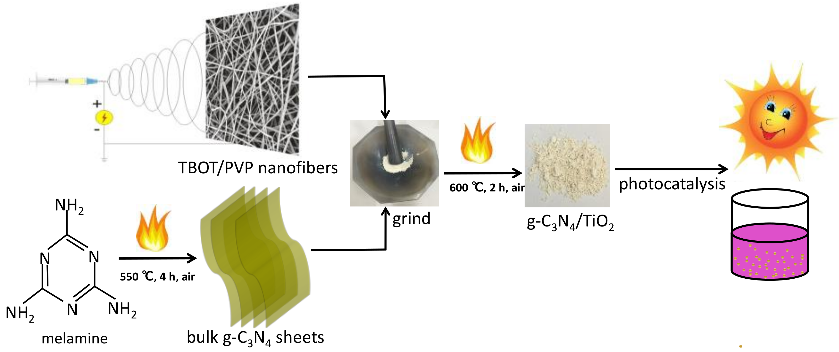
3.1. Synthesis and Application Process

The flow chart of the as-prepared photocatalysts from preparation to application was shown in Figure 1. At the beginning, TBOT/PVP nanofibers were obtained by electrospinning technology [32]. And then the yellow g-C3N4 was synthesized by calcination the melamine at 550 °C for 4 h, following the method mentioned in the literature [36]. Subsequently, the prepared TBOT/PVP nanofibers were mixed and grinded uniformly with g-C3N4 powder in a certain proportion and transferred to a muffle furnace for reannealing. Later, the as-prepared various CNT composites were applied to degrade the contaminant under visible light irradiation.

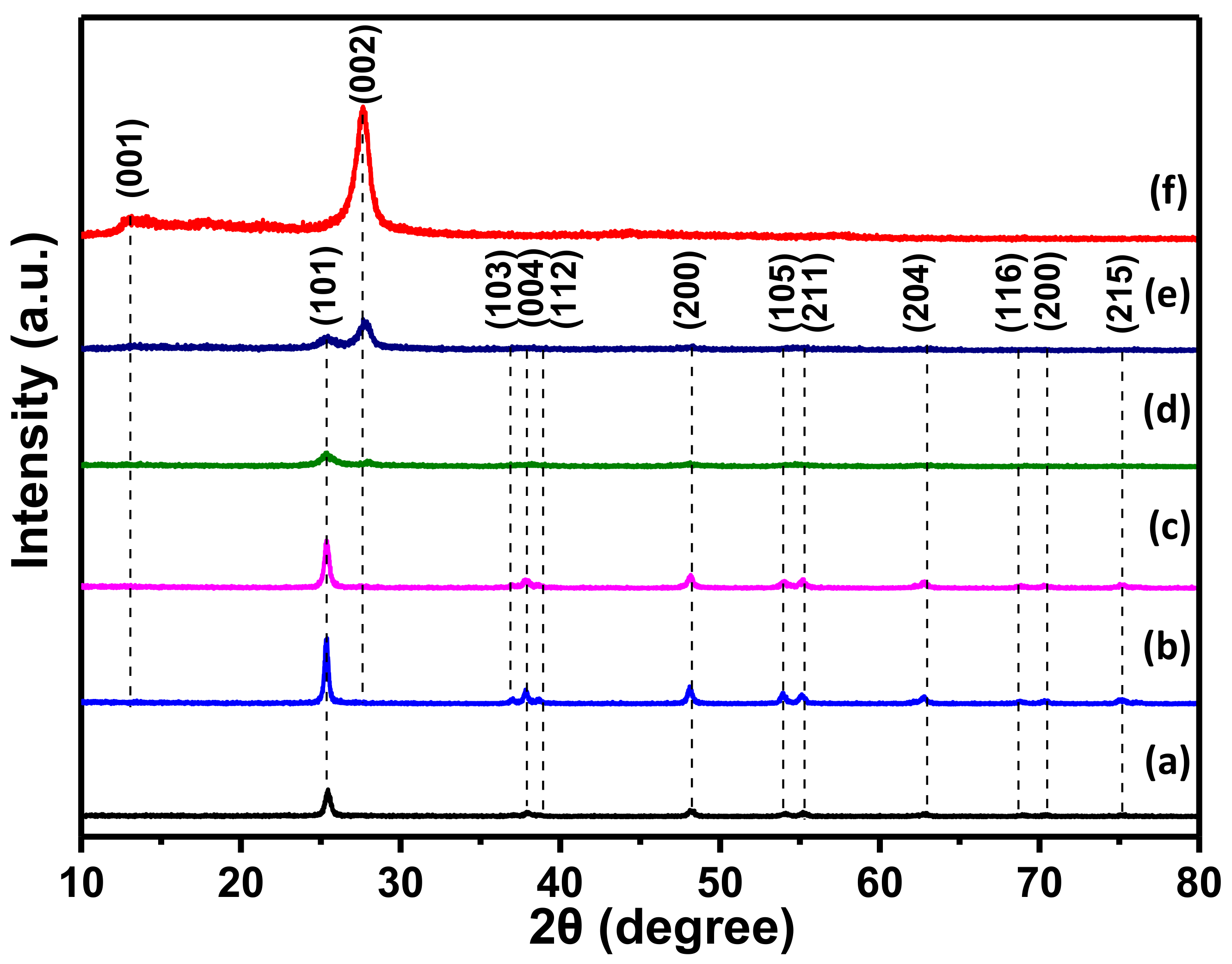
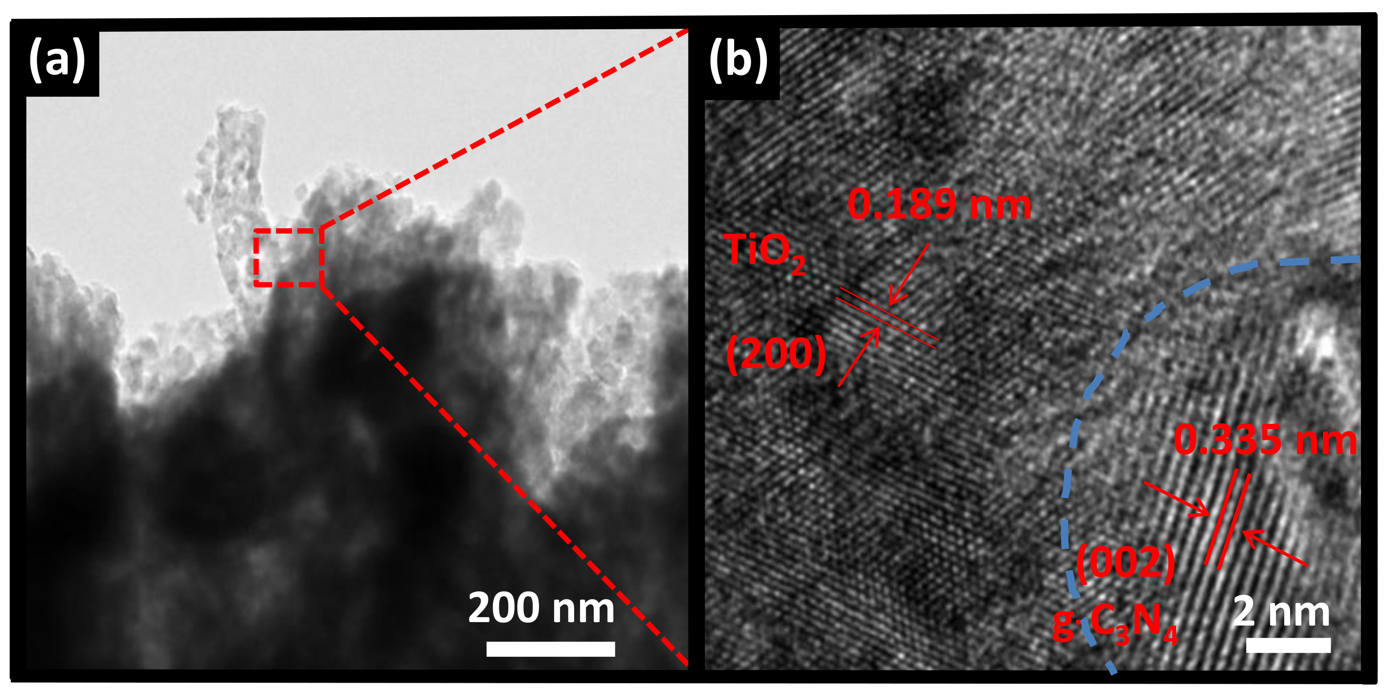
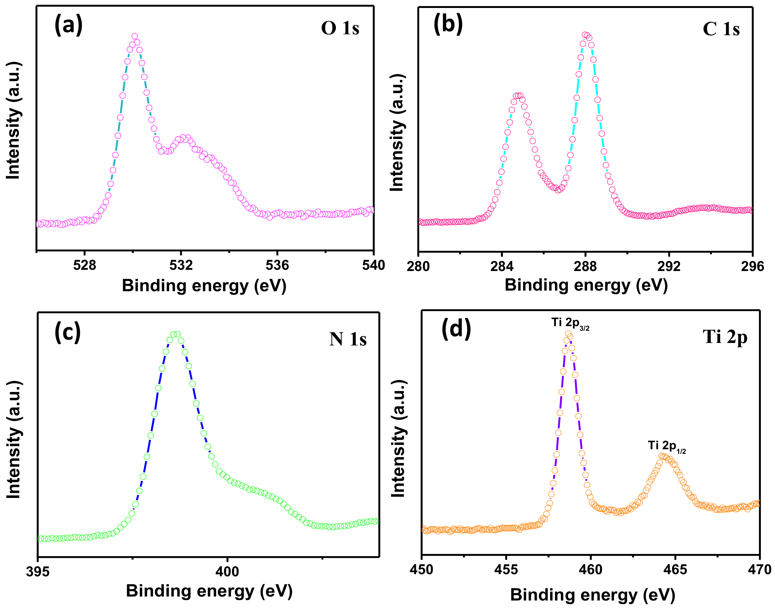
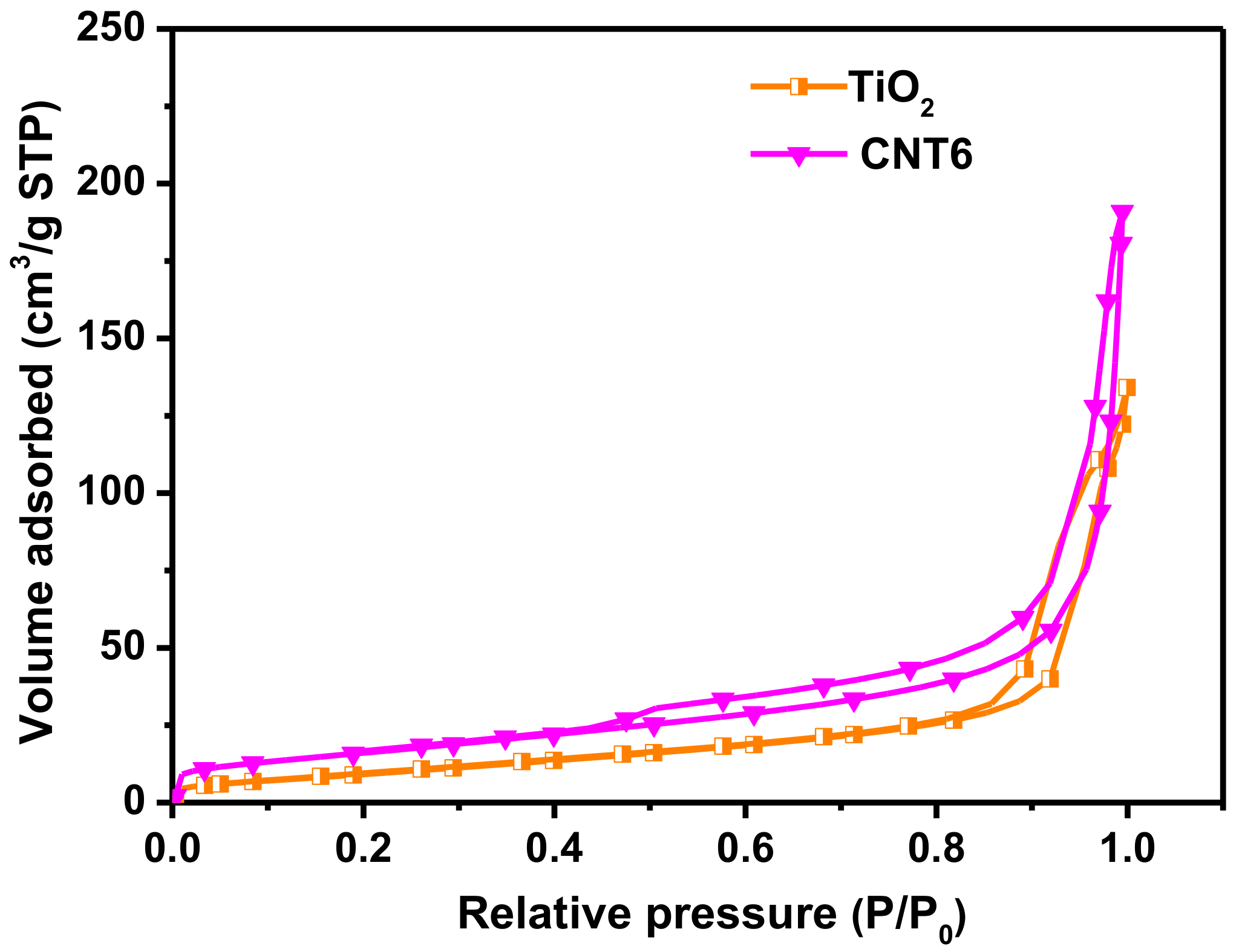
3.2. Structure and Morphology Characteristics

Figure 2 depicts the XRD patterns of g-C3N4, TiO2 and various CNT composites. As shown in Figure 2 curve a, bare TiO2 nanofibers exhibited significant diffraction peaks 2θ at 25.4°, 37.0°, 37.9°, 38.7°, 48.3°, 54.1°, 55.4°, 62.9°, 69.1°, 70.3°, and 75.1°, which were consistent with the (101), (103), (004), (112), (200), (105), (211), (204), (116), (220), and (215) crystal faces of anatase TiO2 (JCPDS 21-1272), respectively [39]. In addition, the crystallized peaks 2θ at 13.1° and 27.5° were related to g-C3N4 phase at (001) and (002) crystal faces (JCPDS 87-1526), respectively [40]. As observed in Figure 2 curves b and c, only bare TiO2 was detected and no other peaks appeared in the XRD patterns, owing to the proportion of added g-C3N4 was less. The diffraction peaks of g-C3N4 increased markedly with the addition of g-C3N4 content (Figure 2 curves d and e), indicating a successful compounded of g-C3N4 to TiO2. This phenomenon was also clearly illustrated by SEM images. In addition, the intensity peaks of TiO2 become lower for the proportion of g-C3N4 increases, proving that the content of g-C3N4 could affect the transformation from TBOT to anatase TiO2. Therefore, the results of XRD can inferred that various CNT composites have been successfully synthesized by the process of electrospinning and calcination.
The detailed structure of heterostructured CNT6 composite has been further confirmed by TEM and HRTEM, as shown in Figure 3a,b, respectively. In TEM image, it could be clearly seen that the fibrous and bulk substances were apparent as TiO2 and g-C3N4, respectively. It seemed that TiO2 was tightly attached the surface of g-C3N4 so the heterostructure formed, although the thickness of the layer of the latter was uncertain. In addition, the TEM image also investigated that the diameter of the nanofiber was less than 100 nm, which was consistent with the results observed in SEM images (Figure S1). In HRTEM image, the well-ordered lattice spacing of TiO2 was measured at 0.189 nm, which was assigned to the exposed (200) plane of anatase TiO2 [41]. In addition, the measured lattice spacing of 0.335 nm can be clearly seen, completely ascribed to the (002) plane of g-C3N4 [42]. Analysis based on SEM, TEM, HRTEM and XPS results for TiO2 and g-C3N4, the formation of CNT heterostructure between g-C3N4 and TiO2 was verified. The close contact interface may contribute to the transfer and separate of photogenerated carriers during the process of light irradiation, which could enhance the performance of photocatalytic. Therefore, the expectation for improving the photocatalytic performance by CNT composite is reasonable.
The surface chemical composition and elemental states of the as-prepared CNT heterstructured composite were studied using XPS. Figure S2 exhibited the XPS survey spectra included O 1s, Ti 2p, C 1s and N 1s for CNT6 composite. In Figure 4a, O 1s spectrum present two characteristic peaks located at 530.1 eV and 532.2 eV corresponded to Ti–O and C=O, respectively [43]. The spectrum of O 1s indicated that TBOT has been converted to TiO2 during the sintering process. The C 1s spectrum in Figure 4b exhibited two major peaks centered at 284.8 eV and 288.1 eV belong to C–C and N–C=N, respectively [44]. Regarding of N 1s spectrum (Figure 4c), the basic units of g-C3N4 mainly contains three N units, presenting in characteristic peaks to sp2 hybridized C=N–C (398.7 eV), tertiary nitrogen N–(C)3 (399.6 eV) and C–N–H groups (401.1 eV) [45]. Meanwhile, the peaks of Ti element in Figure 4d distributed at 458.7 eV and 464.5 eV were ascribed to Ti 2p3/2 and Ti 2p1/2, respectively [46]. The analysis of XPS confirmed the presence of TiO2 and g-C3N4 in the composites. The results further indicate that the g-C3N4/TiO2 heterostructures have been successfully formed, which was matched well with the results obtained by XRD, TEM, UV and PL.
Nitrogen adsorption–desorption isotherms analysis was carried out in using BET method to characterize the properties the specific surface area of TiO2 nanofibers and CNT6 composite (Figure 5) and the corresponding pore size distribution were recorded by using Barrett–Joyner–Halenda (BJH) method (Figure S3). According to the classification of IUPAC [47], both TiO2 nanofibers and CNT6 composite adsorption branches curves exhibit the typical type IV isotherm with H3 hysteresis loops in the relative pressure (P/P0) range about 0.5–1.0, reflecting the slit-like mesopores appear in the products. By BET method, the specific surface area and pore volume of CNT6 were calculated to be 58.71 m2 g−1 and 0.243 cm3 g−1, respectively, which was much super than bare TiO2 nanofibers (34.95 m2 g−1 and 0.18 cm3 g−1). The phenomenon might due to the presence of g-C3N4, which possessing a large specific surface area and have extensive contract with TiO2 to inhibit the stack between g-C3N4 sheets. It could be deduced that heterostructured CNT6 composite was more suitable for meeting the demand as a photocatalyst than bare TiO2 nanofibers, owing to the more adsorption reactive contact sites could be provided during the photocatalytic degradation process. Besides, the pore diameter distribution of CNT6 composite (16.53 nm) tends to be smaller compared to TiO2 nanofibers (20.58 nm), might due to the CNT6 composite surface was covered by TiO2 nanofibers.

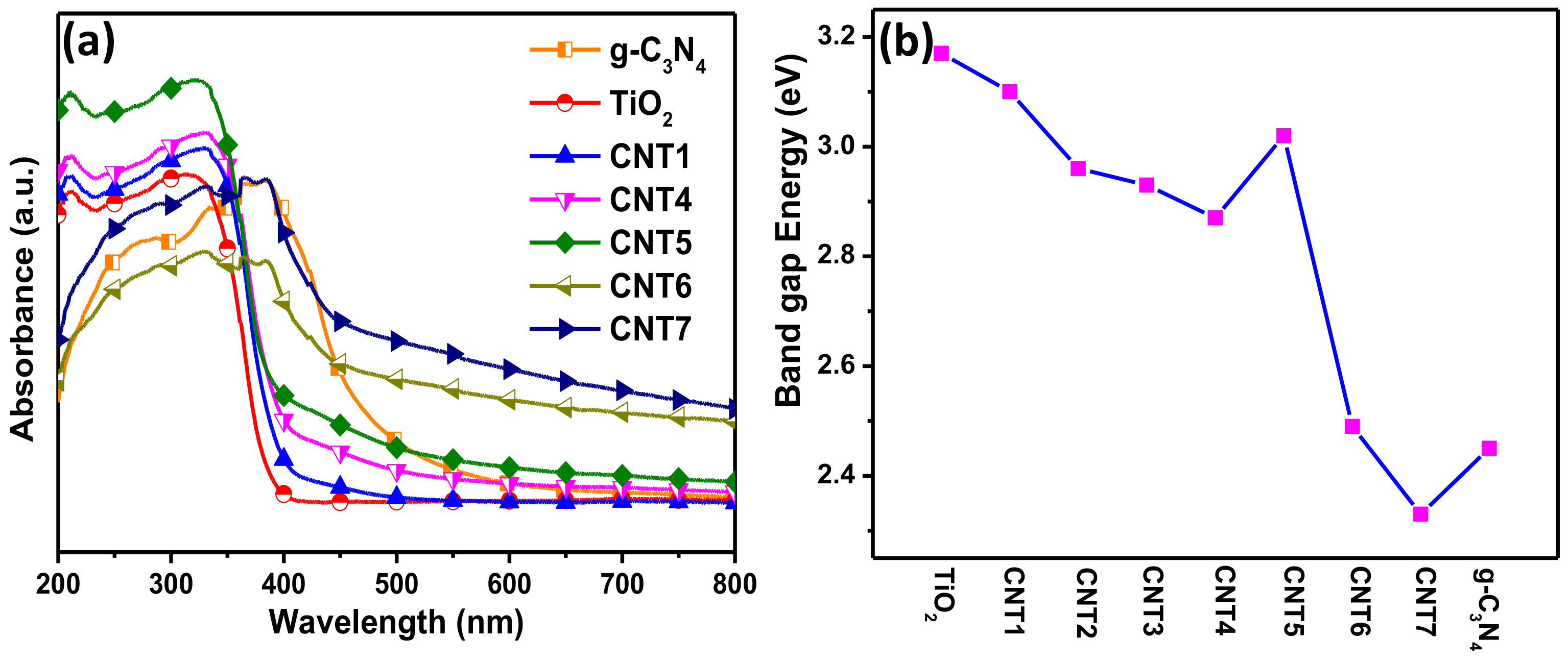
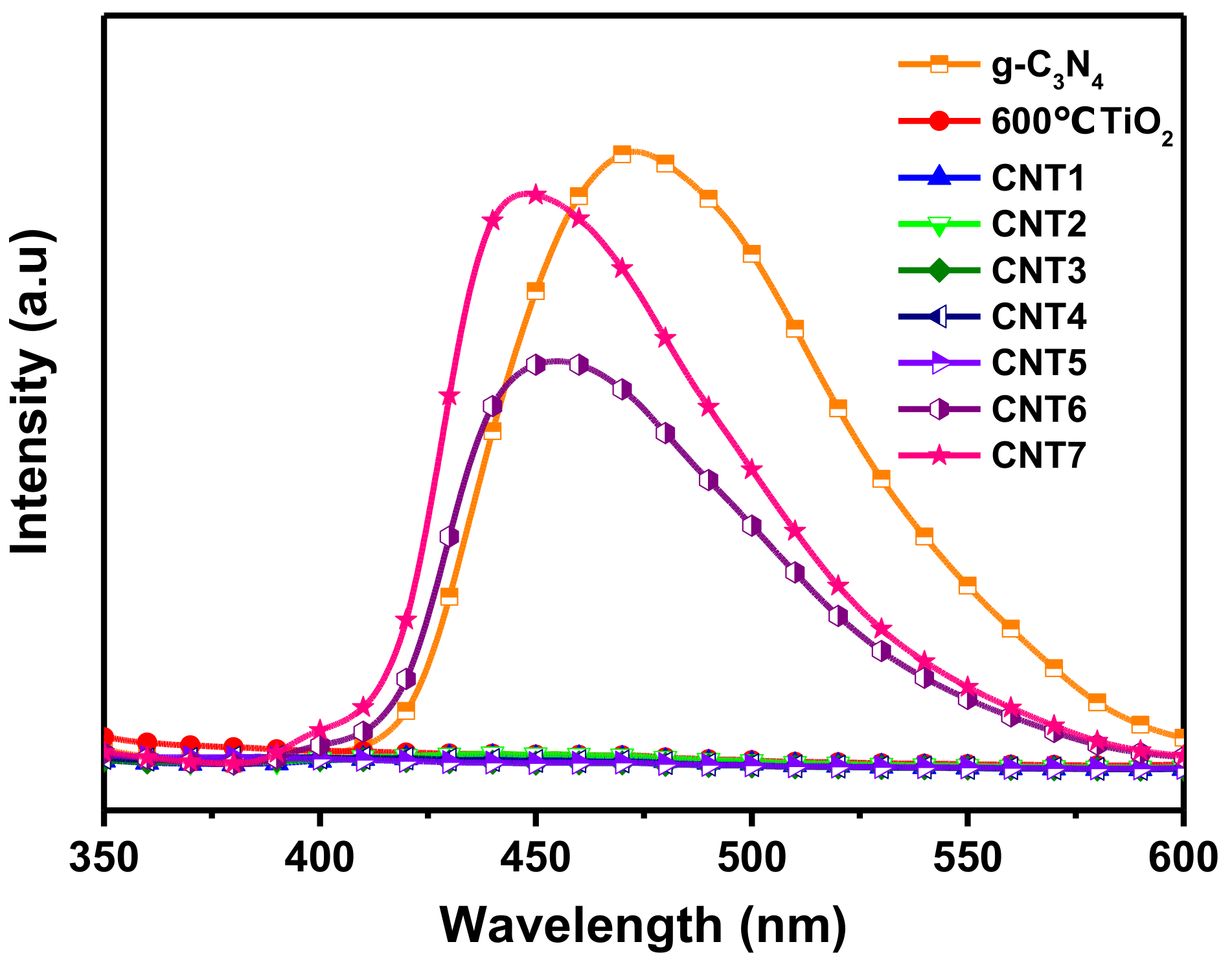
3.3. Optical Characteristics

The optical absorption properties of g-C3N4, TiO2 and various CNT composites were obtained by UV-Vis diffuse reflectance spectra. It can be seen from Figure 6a that all materials have strong absorption in corresponding response light source region. As expect, g-C3N4 with the intrinsic band gap at 2.7 eV exhibits a significant absorption edge at around 450 nm in visible region [48]. The bare TiO2 nanofibers showed the absorption edge at the wavelength of lower than 400 nm in UV region, ascribing to the band gap of 3.2 eV [49]. After compounding the g-C3N4 with TiO2, the CNT composites present evident hybrid adsorption features that the background to capture visible light obviously increased with the increasing of g-C3N4 content in the composites. Obviously, red shift phenomenon has occurred on composites with the increasing of g-C3N4 content, performing that the absorption edge moved moderated toward the infrared zone. The situation was also consistent with the color changes of the resulting products from light yellow to black with the increase of g-C3N4 added amount as shown in Figure S4. The band gap energy range of various CNT composites was estimated at around 2.3 eV–3.1 eV as displayed in Figure 6b. It was calculated by extrapolating the linear region of (hυ·F(R))1/2 versus hυ plot to zero F(R), where hυ is the incident photon energy and values of F(R) can be obtained by using the Kubelka−Munk function: F(R) = (1−R)2/2R [50,51]. The initial curves of (hυ·F(R))1/2 versus hυ were originated from the diffuse reflectance spectra as shown in Figure S5. Thus, it can be concluded that the enhanced ability of CNT composites for capturing the light source could contribute to the improvement of photocatalytic performance.
Since the PL emission is derived from the recombination of photogenerated carriers, PL analysis is an effective technique used in photocatalytic process to investigate the transfer, migrate, and separate of electrons and holes. PL spectra of TiO2 nanofibers and various CNT composites were recorded under the excitation wavelength of 320 nm (Figure 7). For pure g-C3N4, one strong peak centered could see at 473.2 nm was ascribed to the band-band PL phenomenon with the light energy bordering on the band gap energy of g-C3N4 [52]. The PL intensities of all CNT composites were lower than pure g-C3N4, one reason is that the formation of heterostructures indeed promote the separation of photogenerated carriers at the integrated interface, another reason probably because that g-C3N4 occupied is less than the single g-C3N4 in the equivalent amount of the products. Comparing the curves of CNT6, CNT7 and g-C3N4, it was not difficult to find that the intensity of the emission peak has dropped sharply, which was related to the coupled amount of TiO2. Further study the enlarged view of partial curves in Figure 7 as depicted in Figure S6, the PL intensity of CNT1, CNT2, CNT3, CNT4, CNT5 were both decreased than bare TiO2, even the PL intensity of CNT3, CNT4, CNT5 were below than the commercial P25®. Usually, the PL intensity is inversely to the recombination efficiency of the photogenerated carriers. In other words, the lower the PL intensity, the longer the lifetime of the electrons and holes are, and the better performance performs of the corresponding photocatalyst [53]. Therefore, a suitable ratio of CNT composite is beneficial to improve the photocatalytic performance towards degrading pollutants.

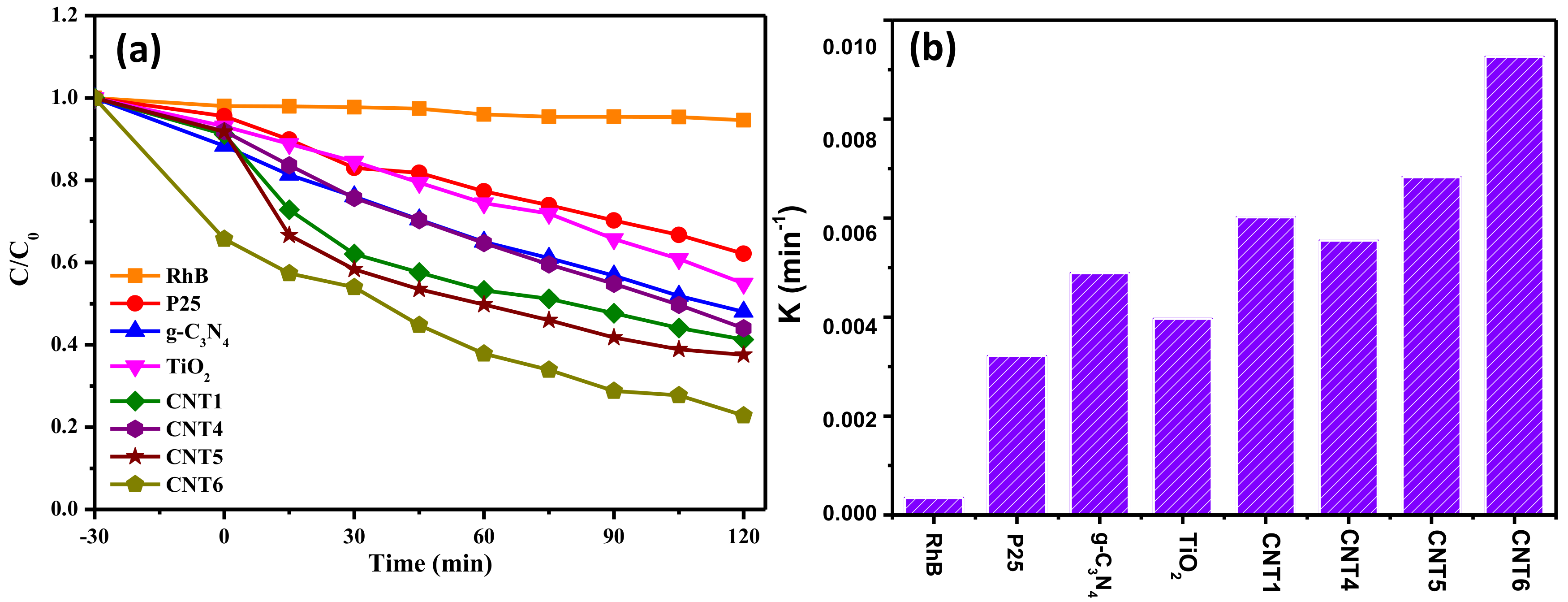
3.4. Photocatalytic Performances

The photocatlytic performances of the as-prepared samples were evaluated by monitoring the concentration changes in RhB over time under visible light irradiation. In addition, the system was adsorbed in the dark for 30 min to ensure an adsorption-desorption balance achieved. Figure 8a presents the comparison curves of the concentration in RhB degradation by pure g-C3N4, bare TiO2 nanofibers, commercial P25® and partial as-prepared CNT composites within the same time. After dark state adsorption, CNT6 exhibits the best adsorption effect due to the large specific surface area. Figure 8a showed that the concentration changes of RhB can be neglected throughout the photocatalytic process in the absence of photocatalyst, indicating that RhB was relatively stable under visible light irradiation. It can be seen from Figure 8a that the CNT composites reaction system has better photocatalytic performance for degradation of RhB than single material and commercial P25® reaction systems, which was attributed to the effective separation of photogenerated carriers at the intimate contact interface and the enlarged specific surface area. Surprisingly, the wide band gap of TiO2 has restricted the range of light absorption wavelength, while it still has good photocatalytic performance in the visible light range. One detailed reason could ascribe that the RhB chromosphere absorbed the visible light and caused the electrons from ground state jumped to the excited state. Subsequently, the excited state electrons rapidly transferred to the conduction band (CB) of TiO2, resulting in degradation of RhB [54]. Another reason might owing to the material inherent oxygen vacancy defects and thus altered the range of absorbed light to degradation the RhB. As expect, the as-prepared heterostructured CNT6 showed the optimal photocatalytic performance instead of the as-prepared maximum g-C3N4 amount loaded in the composite (Figure S7). Hence, it should be noted that the suitable amount of g-C3N4 bonded in the composite could greatly affect the performance of photocatalysis. The results indicated that the as-prepared product had excellent photocatalytic performance and was suitable as a photocatalyst for harnessing the actual environmental pollution. The photocatalytic degradation of RhB could be expressed as a pseudo-first-order kinetics process, which followed the equation below: [55]
−ln(C/C0) = kappt
where kapp was the reaction rate constant, and C and C0 were the concentration of RhB detected at initial t0 and t, respectively. Figure 8b displayed the reaction rate constant of degradation RhB over different as-prepared photocatalysts, which was stemmed from Figure S7. According to the equation, the reaction rate constant of CNT6 was calculated as 9.83 × 10⁻³ min−1, which was nearly 2.5 times and 3 times higher than that of TiO2 nanofibers (4.21 × 10⁻³ min−1) and commercial P25® (3.41 × 10⁻³ min−1), respectively.

3.5. Reaction Mechanisms

To further study the possible reaction mechanism of the as-prepared photocatalyst, series comparative experiments of radical scavengers were carried out in the reaction system to demonstrate the active species that dominated the photocatalysis process. Added scavengers of N2, EDTA-2Na, AgNO3 and TBA were correspond for quenching active species of O 2 , h+, e and OH, respectivity. As can be seen in Figure 9a, the performances of photocatalysis both have the minor changes in the addition of EDTA-2Na, AgNO3 and TBA, respectively, meaning that h+, e and OH played a weaker role in the decomposition of RhB. When N2 was added into the solution, the remove rate of RhB over CNT6 reduced drastically, suggesting that O 2 played the leading role in the photocatalytic process.
Based on the above results, a reasonable photocatalytic mechanism of heterostructured CNT for degradation RhB under visible light irradiation was proposed in detail, as displayed in Figure 9b. Under the irradiation of visible light, the photogenerated electrons (e) of g-C3N4 and TiO2 were both excited from valence band (VB) to CB, leaving the same amount of holes (h+) on the VB. Since the conduction edge potential of TiO2 was higher than that of g-C3N4, the electrons of g-C3N4 on CB were then quickly flowed into the CB of TiO2 through the contact interface. Correspondingly, the holes on VB of TiO2 were rapidly transferred into the VB of g-C3N4 because the VB potential of former was more negative than latter. Eventually, photogenerated carriers were separated at the intimate interface, thus prolonging the survival time of electrons and holes. The oxygen radicals ( O 2 ) attached to the surface of the photocatalyst were generated from that the electrons have transferred to the CB of TiO2 been captured by O2 in the solution, possessing strong oxidizing properties on the surface of the photocatalyst ( O 2 + e O 2 ) [56]. Accordingly, the holes moved to the VB of g-C3N4 having strong oxidative could react with H2O or O2 to yield hydroxyl radicals ( OH ) ( H 2 O , OH + h + OH ) [57]. Oxygen radicals and hydroxyl radicals possessed strong oxidizing, can effectively oxidized the organic pollutant RhB in solution transferred into H2O and CO2. The mechanism of degradation pathway for RhB was proposed. The degradation of RhB mainly via two steps: N-demethylation and cracking of the conjugated structure. After the main steps of chromophore crack, ring opening and mineralization were completed in the photocatalytic process, the dye was converted to smaller organic species. Finally, the products were mineralization with other organic functional groups to form H2O and CO2 [58,59]. It is worth noting that the content of g-C3N4 in CNT composites has a significant influence on the separation and recombination efficiency of photogenerated carriers, which has been discussed in PL spectra. An optimal ratio of CNT composite could behave the outstanding photocatalytic performance towards degradation of pollutants under the visible light irradiation.

4. Conclusions

In this paper, novel heterostructured g-C3N4/TiO2 (CNT) composites were successfully fabricated by using g-C3N4 precursor and TBOT/PVP nanofibers via the electrospinning technology [60,61,62,63,64], grinding treatment followed by the calcination process. Under the visible light irradiation, CNT composites exhibited considerable photocatalytic performance on the photocatalytic process for purifying organic contaminant as comparing with commercial TiO2 P25® and pure electrospun TiO2 nanofibers. An appropriate amount of g-C3N4 addition can expand the absorption light range of the composites to the visible light region and enlarge the specific surface area of as-prepared materials. The enhanced performance of the photocatalyst was attributed to the formation of heterostructures between g-C3N4 and TiO2 nanofibers, thus the charges on tightly-coupled interface can quickly transferred and separated. Based on the admirable photocatalytic performance of CNT composite in the process of photocatalysis, the as-prepared products can be treated as prospective materials to government the pollutants in environmental.

Supplementary Materials

The following are available online at https://www.mdpi.com/2079-4991/8/10/842/s1, Figure S1: SEM images of (a) g-C3N4, (b) TiO2 nanofibers, (c,d) CNT6 composite, Figure S2: XPS survey spectra of CNT6, Figure S3: The pore size distribution of TiO2 nanofibers and CNT6 composite, Figure S4: Optical images of different products: (a) bare TiO2 nanofibers, (b) g-C3N4, (c) CNT2, (d) CNT4, (e) CNT6, and (f) CNT7, Figure S5: The curves of (hν·F(R))1/2 versus hν originated from the diffuse reflectance spectra, Figure S6: PL spectra of commercial TiO2 P25 and the enlarged view of partial curves in Figure 6, Figure S7: (a) Photocatalytic degradation RhB curves under visible light irradiation over different samples, (b) kinetic curves of degradation RhB over different as-prepared photocatalysts.

Author Contributions

Conceptualization, H.L. and Z.-G.Z.; Software, H.L.; Validation, H.-W.H. and H.L.; Formal Analysis, Z.-G.Z. and X.-X.W.; Investigation, Q.-Q.Z. and Y.-F.T.; Resources, S.R., S.-Y.Y. and Y.-Z.L.; Data Curation, H.L. and H.-L.L; Writing-Original Draft Preparation, H.L.; Writing-Review & Editing, H.L., Z.-G.Z. and Y.-Z.L.; Supervision, S.R., J.Z. and Y.-Z.L.

Funding

Our work was supported by the National Natural Science Foundation of China (51673103), Shandong Provincial Natural Science Foundation, China (ZR2017BA013), China Postdoctoral Science Foundation (2017M612200) and the Postdoctoral Scientific Research Foundation of Qingdao (2016014).

Acknowledgments

All results were obtained at the Qingdao University. We thank two anonymous reviewers for positive and instructive comments.

Conflicts of Interest

The authors declare no conflict of interest.

References

  1. Ding, Q.; Meng, F.; English, C.R.; Cabán-Acevedo, M.; Shearer, M.J.; Liang, D.; Daniel, A.S.; Hamers, R.J.; Jin, S. Efficient photoelectrochemical hydrogen generation using heterostructures of Si and chemically exfoliated metallic MoS2. J. Am. Chem. Soc. 2014, 136, 8504–8507. [Google Scholar] [CrossRef] [PubMed]
  2. Zou, Z.; Ye, J.; Sayama, K.; Arakawa, H. Direct splitting of water under visible light irradiation with an oxide semiconductor photocatalyst. Nature 2001, 414, 625–627. [Google Scholar] [CrossRef] [PubMed]
  3. De Brito, J.F.; Tavella, F.; Genovese, C.; Ampelli, C.; Zanoni, M.V.B.; Centi, G.; Perathoner, S. Role of CuO in the modification of the photocatalytic water splitting behavior of TiO2 nanotube thin films. Appl. Catal. B Environ. 2018, 224, 136–145. [Google Scholar] [CrossRef]
  4. Odenbrand, C.U.I. CaSO4 deactivated V2O5-WO3/TiO2 SCR catalyst for a diesel power plant. Characterization and simulation of the kinetics of the SCR reactions. Appl. Catal. B Environ. 2018, 234, 365–377. [Google Scholar] [CrossRef]
  5. Hao, R.; Wang, G.; Tang, H.; Sun, L.; Xu, C.; Han, D. Template-free preparation of macro/mesoporous g-C3N4/TiO2 heterojunction photocatalysts with enhanced visible light photocatalytic activity. Appl. Catal. B Environ. 2016, 187, 47–58. [Google Scholar] [CrossRef]
  6. Qin, N.; Xiong, J.; Liang, R.; Liu, Y.; Zhang, S.; Li, Y.; Li, Z.; Wu, L. Highly efficient photocatalytic H2 evolution over MoS2/CdS-TiO2 nanofibers prepared by an electrospinning mediated photodeposition method. Appl. Catal. B Environ. 2017, 202, 374–380. [Google Scholar] [CrossRef]
  7. Castro, Y.; Mosa, J.; Aparicio, M.; Pérez-Carrillo, L.A.; Vílchez, S.; Esquena, J.; Durán, A. Sol–gel hybrid membranes loaded with meso/macroporous SiO2, TiO2–P2O5 and SiO2–TiO2–P2O5 materials with high proton conductivity. Mater. Chem. Phys. 2015, 149–150, 686–694. [Google Scholar] [CrossRef]
  8. Hirano, M.; Nakahara, C.; Ota, K.; Tanaike, O.; Inagaki, M. Photoactivity and phase stability of ZrO2-doped anatase-type TiO2 directly formed as nanometer-sized particles by hydrolysis under hydrothermal conditions. J. Solid State Chem. 2003, 170, 39–47. [Google Scholar] [CrossRef]
  9. Ren, W.; Ai, Z.; Jia, F.; Zhang, L.; Fan, X.; Zou, Z. Low temperature preparation and visible light photocatalytic activity of mesoporous carbon-doped crystalline TiO2. Appl. Catal. B Environ. 2007, 69, 138–144. [Google Scholar] [CrossRef]
  10. Takezawa, Y.; Imai, H. Bottom–Up synthesis of Titanate nanosheets with hierarchical structures and a high specific surface area. Small 2006, 2, 390–393. [Google Scholar] [CrossRef] [PubMed]
  11. Yu, H.; Liu, W.; Wang, X.; Wang, F. Promoting the interfacial H2-evolution reaction of metallic Ag by Ag2S cocatalyst: A case study of TiO2/Ag-Ag2S photocatalyst. Appl. Catal. B Environ. 2018, 225, 415–423. [Google Scholar] [CrossRef]
  12. Chen, J.; Qiu, F.; Zhang, Y.; Liang, J.; Zhu, H.; Cao, S. Enhanced supercapacitor performances using C-doped porous TiO2 electrodes. Appl. Surf. Sci. 2015, 356, 553–560. [Google Scholar] [CrossRef]
  13. Kondo, K.; Murakami, N.; Ye, C.; Tsubota, T.; Ohno, T. Development of highly efficient sulfur-doped TiO2 photocatalysts hybridized with graphitic carbon nitride. Appl. Catal. B Environ. 2013, 142–143, 362–367. [Google Scholar] [CrossRef]
  14. Jiang, Z.; Jiang, D.; Yan, Z.; Liu, D.; Qian, K.; Xie, J. A new visible light active multifunctional ternary composite based on TiO2–In2O3 nanocrystals heterojunction decorated porous graphitic carbon nitride for photocatalytic treatment of hazardous pollutant and H2 evolution. Appl. Catal. B Environ. 2015, 170–171, 195–205. [Google Scholar] [CrossRef]
  15. Xu, J.; Wu, F.; Jiang, Q.; Shang, J.K.; Li, Y.X. Metal halides supported on mesoporous carbon nitride as efficient heterogeneous catalysts for the cycloaddition of CO2. J. Mol. Catal. A Chem. 2015, 403, 77–83. [Google Scholar] [CrossRef]
  16. Aguirre, M.E.; Zhou, R.; Eugene, A.J.; Guzman, M.I.; Grela, M.A. Cu2O/TiO2 heterostructures for CO2 reduction through a direct Z-scheme: Protecting Cu2O from photocorrosion. Appl. Catal. B Environ. 2017, 217, 485–493. [Google Scholar] [CrossRef]
  17. Zazpe, R.; Sopha, H.; Prikryl, J.; Krbal, M.; Mistrik, J.; Dvorak, F.; Hromadko, L.; Macak, J.M. A 1D conical nanotubular TiO2/CdS heterostructure with superior photon-to-electron conversion. Nanoscale 2018, 2018. 10, 16601–16612. [Google Scholar] [CrossRef]
  18. Khanchandani, S.; Kumar, S.; Ganguli, A.K. Comparative study of TiO2/CuS core/shell and composite nanostructures for efficient visible light photocatalysis. ACS Sustain. Chem. Eng. 2016, 4, 1487–1499. [Google Scholar] [CrossRef]
  19. Li, P.; Hu, H.; Xu, J.; Jing, H.; Peng, H.; Lu, J.; Wu, C.; Ai, S. New insights into the photo-enhanced electrocatalytic reduction of carbon dioxide on MoS2-rods/TiO2 NTs with unmatched energy band. Appl. Catal. B Environ. 2014, 147, 912–919. [Google Scholar] [CrossRef]
  20. Naseri, A.; Samadi, M.; Pourjavadi, A.; Moshfegh, A.Z.; Ramakrishna, S. Graphitic carbon nitride (g-C3N4)-based photocatalysts for solar hydrogen generation: Recent advances and future development directions. J. Mater. Chem. A 2017, 5, 23406–23433. [Google Scholar] [CrossRef]
  21. Cao, S.; Low, J.; Yu, J.; Jaroniec, M. Polymeric photocatalysts based on graphitic carbon nitride. Adv. Mater. 2015, 27, 2150–2176. [Google Scholar] [CrossRef] [PubMed]
  22. Ong, W.J.; Tan, L.L.; Ng, Y.H.; Yong, S.T.; Chai, S.P. Graphitic carbon nitride (g-C3N4)-based photocatalysts for artificial photosynthesis and environmental remediation: Are we a step closer to achieving sustainability? Chem. Rev. 2016, 116, 7159–7329. [Google Scholar] [CrossRef] [PubMed]
  23. Wan, Z.; Zhang, G.; Wu, X.; Yin, S. Novel visible-light-driven Z-scheme Bi12GeO20/g-C3N4 photocatalyst: Oxygen-induced pathway of organic pollutants degradation and proton assisted electron transfer mechanism of Cr(VI) reduction. Appl. Catal. B Environ. 2017, 207, 17–26. [Google Scholar] [CrossRef]
  24. Bellardita, M.; García-López, E.I.; Marcì, G.; Krivtsov, I.; García, J.R.; Palmisano, L. Selective photocatalytic oxidation of aromatic alcohols in water by using P-doped g-C3N4. Appl. Catal. B Environ. 2018, 220, 222–233. [Google Scholar] [CrossRef]
  25. Da Silva, G.T.S.T.; Carvalho, K.T.G.; Lopes, O.F.; Ribeiro, C. g-C3N4/Nb2O5 heterostructures tailored by sonochemical synthesis: Enhanced photocatalytic performance in oxidation of emerging pollutants driven by visible radiation. Appl. Catal. B Environ. 2017, 216, 70–79. [Google Scholar] [CrossRef]
  26. Wang, F.; Wang, Y.; Feng, Y.; Zeng, Y.; Xie, Z.; Zhang, Q.; Su, Y.; Chen, P.; Liu, Y.; Yao, K.; et al. Novel ternary photocatalyst of single atom-dispersed silver and carbon quantum dots co-loaded with ultrathin g-C3N4 for broad spectrum photocatalytic degradation of naproxen. Appl. Catal. B Environ. 2018, 221, 510–520. [Google Scholar] [CrossRef]
  27. Li, K.; Huang, Z.; Zeng, X.; Huang, B.; Gao, S.; Lu, J. Synergetic effect of Ti3+ and oxygen doping on enhancing photoelectrochemical and photocatalytic properties of TiO2/g-C3N4 heterojunctions. ACS Appl. Mater. Inter. 2017, 9, 11577–11586. [Google Scholar] [CrossRef] [PubMed]
  28. Lu, L.; Wang, G.; Zou, M.; Wang, J.; Li, J. Effects of calcining temperature on formation of hierarchical TiO2/g-C3N4 hybrids as an effective Z-scheme heterojunction photocatalyst. Appl. Surf. Sci. 2018, 441, 1012–1023. [Google Scholar] [CrossRef]
  29. Lu, Z.; Zeng, L.; Song, W.; Qin, Z.; Zeng, D.; Xie, C. In situ synthesis of C-TiO2/g-C3N4 heterojunction nanocomposite as highly visible light active photocatalyst originated from effective interfacial charge transfer. Appl. Catal. B Environ. 2017, 202, 489–499. [Google Scholar] [CrossRef]
  30. Han, C.; Wang, Y.; Lei, Y.; Wang, B.; Wu, N.; Shi, Q.; Li, Q. In situ synthesis of graphitic-C3N4 nanosheet hybridized N-doped TiO2 nanofibers for efficient photocatalytic H2 production and degradation. Nano Res. 2015, 8, 1199–1209. [Google Scholar] [CrossRef]
  31. Lu, D.; Fang, P.; Wu, W.; Ding, J.; Jiang, L.; Zhao, X.; Li, C.; Yang, M.; Li, Y.; Wang, D. Solvothermal-assisted synthesis of self-assembling TiO2 nanorods on large graphitic carbon nitride sheets with their anti-recombination in the photocatalytic removal of Cr(VI) and rhodamine B under visible light irradiation. Nanoscale 2017, 9, 3231–3245. [Google Scholar] [CrossRef] [PubMed]
  32. Wang, X.; Song, W.Z.; You, M.H.; Zhang, J.; Yu, M.; Fan, Z.; Ramakrishna, S.; Long, Y.-Z. Bionic single-electrode electronic skin unit based on piezoelectric nanogenerator. ACS Nano 2018, 12, 8588–8596. [Google Scholar] [CrossRef] [PubMed]
  33. Zhang, J.; Wang, X.X.; Zhang, B.; Ramakrishna, S.; Yu, M.; Ma, J.W.; Long, Y.Z. In situ assembly of well-dispersed Ag nanoparticles throughout electrospun alginate nanofibers for monitoring human breath—Smart fabrics. ACS Appl. Mater. Inter. 2018, 10, 19863. [Google Scholar] [CrossRef] [PubMed]
  34. Hu, W.; Zhang, B.; Luo, W.; Zhang, J.; Guo, Y.; Chen, S.; Yun, M.; Ramakrishna, S.; Long, Y.Z. Ag/alginate nanofiber membrane for flexible electronic skin. Nanotechnology 2017, 28, 445502. [Google Scholar] [CrossRef] [PubMed] [Green Version]
  35. Zhang, B.; Zhang, Z.G.; Yan, X.; Wang, X.X.; Zhao, H.; Guo, J.; Feng, J.Y.; Long, Y.Z. Chitosan nanostructures by in situ electrospinning for high-efficiency PM2.5 capture. Nanoscale 2017, 9, 4154–4161. [Google Scholar] [CrossRef] [PubMed]
  36. Yan, S.C.; Li, Z.S.; Zou, Z.G. Photodegradation performance of g-C3N4 fabricated by directly heating melamine. Langmuir 2009, 25, 10397–10401. [Google Scholar] [CrossRef] [PubMed]
  37. Zhou, R.; Guzman, M.I. CO2 reduction under periodic illumination of ZnS. J. Phys. Chem. C 2014, 118, 11649–11656. [Google Scholar] [CrossRef]
  38. Zhou, R.; Guzman, M.I. Photocatalytic reduction of fumarate to succinate on ZnS mineral surfaces. J. Phys. Chem. C 2016, 120, 7349–7357. [Google Scholar] [CrossRef]
  39. Liu, H.; Zhang, Z.G.; Wang, X.X.; Nie, G.D.; Zhang, J.; Zhang, S.X.; Cao, N.; Yan, S.Y.; Long, Y.Z. Highly flexible Fe2O3/TiO2 composite nanofibers for photocatalysis and utraviolet detection. J. Phys. Chem. Solids 2018, 121, 236–246. [Google Scholar] [CrossRef]
  40. Sun, Y.; Zhang, W.; Xiong, T.; Zhao, Z.; Dong, F.; Wang, R.; Ho, W.-K. Growth of BiOBr nanosheets on C3N4 nanosheets to construct two-dimensional nanojunctions with enhanced photoreactivity for NO removal. J. Colloid Interf. Sci. 2014, 418, 317–323. [Google Scholar] [CrossRef] [PubMed]
  41. Darabdhara, G.; Boruah, P.K.; Borthakur, P.; Hussain, N.; Das, M.R.; Ahamad, T.; Alshehri, S.M.; Malgras, V.; Wu, K.C.W.; Yamauchi, Y. Reduced graphene oxide nanosheets decorated with Au–Pd bimetallic alloy nanoparticles towards efficient photocatalytic degradation of phenolic compounds in water. Nanoscale 2016, 8, 8276–8287. [Google Scholar] [CrossRef] [PubMed]
  42. Pan, F.; Cao, Z.; Zhao, Q.; Liang, H.; Zhang, J. Nitrogen-doped porous carbon nanosheets made from biomass as highly active electrocatalyst for oxygen reduction reaction. J. Power Sources 2014, 272, 8–15. [Google Scholar] [CrossRef]
  43. Liu, C.; Wang, L.; Tang, Y.; Luo, S.; Liu, Y.; Zhang, S.; Zeng, Y.; Xu, Y. Vertical single or few-layer MoS2 nanosheets rooting into TiO2 nanofibers for highly efficient photocatalytic hydrogen evolution. Appl. Catal. B Environ. 2015, 164, 1–9. [Google Scholar] [CrossRef]
  44. Liang, Q.; Li, Z.; Yu, X.; Huang, Z.H.; Kang, F.; Yang, Q.H. Macroscopic 3D porous graphitic carbon nitride monolith for enhanced photocatalytic hydrogen evolution. Adv. Mater. 2015, 27, 4634–4639. [Google Scholar] [CrossRef] [PubMed]
  45. Jiang, X.H.; Xing, Q.J.; Luo, X.B.; Li, F.; Zou, J.P.; Liu, S.S.; Li, X.; Wang, X.K. Simultaneous photoreduction of Uranium(VI) and photooxidation of Arsenic(III) in aqueous solution over g-C3N4/TiO2 heterostructured catalysts under simulated sunlight irradiation. Appl. Catal. B Environ. 2018, 228, 29–38. [Google Scholar] [CrossRef]
  46. Zheng, F.; Wang, Z.; Chen, J.; Li, S. Synthesis of carbon quantum dot-surface modified P25 nanocomposites for photocatalytic degradation of p-nitrophenol and acid violet 43. RSC Adv. 2014, 4, 30605–30609. [Google Scholar] [CrossRef]
  47. Thommes, M.; Kaneko, K.; Neimark, A.V.; Olivier, J.P.; Rodriguezreinoso, F.; Rouquerol, J.; Sing, K.S.W. Physisorption of gases, with special reference to the evaluation of surface area and pore size distribution (IUPAC Technical Report). Pure Appl. Chem. 2016, 38, 25–25. [Google Scholar] [CrossRef]
  48. Li, G.; Nie, X.; Gao, Y.; An, T. Can environmental pharmaceuticals be photocatalytically degraded and completely mineralized in water using g-C3N4/TiO2 under visible light irradiation?—Implications of persistent toxic intermediates. Appl. Catal. B Environ. 2016, 180, 726–732. [Google Scholar] [CrossRef]
  49. Chen, Y.; Huang, W.; He, D.; Situ, Y.; Huang, H. Construction of heterostructured g-C₃N₄/Ag/TiO₂ microspheres with enhanced photocatalysis performance under visible-light irradiation. ACS Appl. Mater. Inter. 2014, 6, 14405. [Google Scholar] [CrossRef] [PubMed]
  50. Fujisawa, J.I.; Matsumura, S.; Hanaya, M. A single TiOC linkage induces interfacial charge-transfer transitions between TiO2 and a π-conjugated molecule. Chem. Phys. Lett. 2016, 657, 172–176. [Google Scholar] [CrossRef]
  51. Li, R.; Yu, L.; Yan, X.; Tang, Q. Efficient photocatalysts from polymorphic cuprous oxide/zinc oxide microstructures. RSC Adv. 2015, 5, 11917–11924. [Google Scholar] [CrossRef]
  52. Huang, Z.A.; Sun, Q.; Lv, K.; Zhang, Z.; Li, M.; Li, B. Effect of contact interface between TiO2 and g-C3N4 on the photoreactivity of g-C3N4/TiO2 photocatalyst: (001) vs. (101) facets of TiO2. Appl. Catal. B Environ. 2015, 164, 420–427. [Google Scholar] [CrossRef]
  53. Jiang, F.; Yan, T.; Chen, H.; Sun, A.; Xu, C.; Wang, X. A g-C3N4–CdS composite catalyst with high visible-light-driven catalytic activity and photostability for methylene blue degradation. Appl. Surf. Sci. 2014, 295, 164–172. [Google Scholar] [CrossRef]
  54. Pan, L.; Zou, J.J.; Zhang, X.; Wang, L. Water-mediated promotion of dye sensitization of TiO2 under visible light. J. Am. Chem. Soc. 2011, 133, 10000–10002. [Google Scholar] [CrossRef] [PubMed]
  55. Tan, C.; Zhu, G.; Hojamberdiev, M.; Okada, K.; Liang, J.; Luo, X.; Liu, P.; Liu, Y. Co3O4 nanoparticles-loaded BiOCl nanoplates with the dominant {001} facets: Efficient photodegradation of organic dyes under visible light. Appl. Catal. B Environ. 2014, 152–153, 425–436. [Google Scholar] [CrossRef]
  56. Chai, B.; Peng, T.; Mao, J.; Li, K.; Zan, L. Graphitic carbon nitride (g-C3N4)-Pt-TiO2 nanocomposite as an efficient photocatalyst for hydrogen production under visible light irradiation. Phys. Chem. Chem. Phys. 2012, 14, 16745. [Google Scholar] [CrossRef] [PubMed]
  57. He, Y.; Zhang, L.; Teng, B.; Fan, M. New application of Z-Scheme Ag3PO4/g-C3N4 composite in converting CO2 to fuel. Environ. Sci. Technol. 2015, 49, 649–656. [Google Scholar] [CrossRef] [PubMed]
  58. Hisaindee, S.; Meetani, M.A.; Rauf, M.A. Application of LC-MS to the analysis of advanced oxidation process (AOP) degradation of dye products and reaction mechanisms. TRAC Trend Anal. Chem. 2013, 49, 31–44. [Google Scholar] [CrossRef]
  59. Idrees, F.; Cao, C.; Ahmed, R.; Butt, F.K.; Butt, S.; Tahir, M.; Tanveer, M.; Aslam, I.; Ali, Z. Novel nano-flowers of Nb2O5 by template free synthesis and enhanced photocatalytic response under visible light. Sci. Adv. Mater. 2015, 7, 4204–4220. [Google Scholar] [CrossRef]
  60. Sun, B.; Long, Y.Z.; Zhang, H.D.; Li, M.M.; Duvail, J.L.; Jiang, X.Y.; Yin, H.L. Advances in three-dimensional nanofibrous macrostructures via electrospinning. Prog. Polym. Sci. 2014, 39, 862–890. [Google Scholar] [CrossRef]
  61. Liu, S.; Liu, S.L.; Long, Y.Z.; Liu, L.Z.; Zhang, H.D.; Zhang, J.C.; Han, W.P.; Liu, Y.C. Fabrication of p-type ZnO nanofibers by electrospinning for field-effect and rectifying devices. Appl. Phys. Lett. 2014, 104, 042105. [Google Scholar] [CrossRef]
  62. Zhang, B.; Yan, X.; He, H.W.; Yu, M.; Ning, X.; Long, Y.Z. Solvent-free electrospinning: Opportunities and challenges. Polym. Chem. 2016, 8, 333–352. [Google Scholar] [CrossRef]
  63. Wang, L.; Yang, J.; Ran, B.; Yang, X.; Zheng, W.; Long, Y.Z.; Jiang, X. Small molecular TGF-β1 inhibitor loaded electrospun fibrous scaffolds for preventing hypertrophic scars. ACS Appl. Mater. Inter. 2017, 9, 32545–32553. [Google Scholar] [CrossRef] [PubMed]
  64. Zhang, Z.G.; Liu, H.; Zhang, B.; Zhang, J.; Liu, R.Z.; Ning, X.; Long, Y.Z. Synthesis and application of highly ordered arrays of TiO2 rods grown on electrospun PVDF fibers. Mater. Res. Express 2017, 4, 075907. [Google Scholar] [CrossRef]
Figure 1. Schematic illustration for the synthesis and visible light photocatalytic application of the CNT composite.
Nanomaterials 08 00842 g001
Figure 2. XRD patterns of (a) TiO2 nanofibers; (b) CNT1; (c) CNT3; (d) CNT5; (e) CNT6 and (f) g-C3N4 synthesized at 550 °C.
Nanomaterials 08 00842 g002
Figure 3. (a) TEM and (b) HRTEM images of heterostructured CNT6 composite.
Nanomaterials 08 00842 g003
Figure 4. XPS spectra of CNT6: (a) O 1s region; (b) C 1s region; (c) N 1s region and (d) Ti 2p region.
Nanomaterials 08 00842 g004
Figure 5. Nitrogen adsorption–desorption isotherms.
Nanomaterials 08 00842 g005
Figure 6. (a) UV-vis diffuses reflectance spectra of g-C3N4, TiO2 nanofibers and various CNT composites; (b) The curve of band gap energy in various samples.
Nanomaterials 08 00842 g006
Figure 7. PL spectra of TiO2 nanofibers and various CNT composites.
Nanomaterials 08 00842 g007
Figure 8. (a) Photocatalytic degradation RhB curves under visible light irradiation over different samples; (b) reaction rate constant for degradation RhB over different as-prepared photocatalysts.
Nanomaterials 08 00842 g008
Figure 9. (a) Effects on photocatalytic performance by adding different kinds of scavengers; (b) Schematic illustration for the separation and recombination process of photogenerated carriers between TiO2 and g-C3N4 under visible light irradiation.
Nanomaterials 08 00842 g009
Table 1. Description of various as-prepared g-C3N4/TiO2 (CNT) composite.
SamplesCNT1CNT2CNT3CNT4CNT5CNT6CNT7
g-C3N4 (g)0.250.30.51234
TBOT/PVP (g)1111111

