Article

Wettability of Y2O3: A Relative Analysis of Thermally Oxidized, Reactively Sputtered and Template Assisted Nanostructured Coatings

by
Harish C. Barshilia
*,
Archana Chaudhary
,
Praveen Kumar
and
Natarajan T. Manikandanath
Surface Engineering Division, CSIR-National Aerospace Laboratories, Bangalore-560017, India
*
Author to whom correspondence should be addressed.
Nanomaterials 2012, 2(1), 65-78; https://doi.org/10.3390/nano2010065
Submission received: 6 December 2011 / Revised: 17 January 2012 / Accepted: 21 February 2012 / Published: 29 February 2012

Abstract

:
The wettability of reactively sputtered Y2O3, thermally oxidized Y-Y2O3 and Cd-CdO template assisted Y2O3 coatings has been studied. The wettability of as-deposited Y2O3 coatings was determined by contact angle measurements. The water contact angles for reactively sputtered, thermally oxidized and template assisted Y2O3 nanostructured coatings were 99°, 117° and 155°, respectively. The average surface roughness values of reactively sputtered, thermally oxidized and template assisted Y2O3 coatings were determined by using atomic force microscopy and the corresponding values were 3, 11 and 180 nm, respectively. The low contact angle of the sputter deposited Y2O3 and thermally oxidized Y-Y2O3 coatings is attributed to a densely packed nano-grain like microstructure without any void space, leading to low surface roughness. A water droplet on such surfaces is mostly in contact with a solid surface relative to a void space, leading to a hydrophobic surface (low contact angle). Surface roughness is a crucial factor for the fabrication of a superhydrophobic surface. For Y2O3 coatings, the surface roughness was improved by depositing a thin film of Y2O3 on the Cd-CdO template (average roughness = 178 nm), which resulted in a contact angle greater than 150°. The work of adhesion of water was very high for the reactively sputtered Y2O3 (54 mJ/m2) and thermally oxidized Y-Y2O3 coatings (43 mJ/m2) compared to the Cd-CdO template assisted Y2O3 coating (7 mJ/m2).

1. Introduction

The wettability property of a solid surface is important scientifically and technologically. The surface morphological structure and surface chemistry mainly control the wetting or repellant behavior of the solid surface. Contact angle measurement commonly determines the wettability of a solid surface. For a liquid on a flat solid surface the contact angle is measured as the combined result of three different types of interface tension at the solid, liquid and gas interfaces given by the classical Young’s equation:
Nanomaterials 02 00065 i001
where γSV, γSL, and γLV are the interfacial free energies per unit area of solid-vapor, solid-liquid, and liquid-vapor interfaces. Young's equation tells us that hydrophobicity refers to a contact angle greater than 90° while a contact angle less than 90° implies hydrophilicity. Solid surfaces are usually not perfectly flat but are somewhat rough, so the effect of surface roughness has to be considered for surface wettability. The Wenzel and Cassie-Baxter models describe the effect of morphological parameters such as surface roughness on the wettability of solid surfaces [1,2]. The Wenzel model assumes that the liquid can enter completely and contact the concave regions on the solid surface. Young’s equation was modified by Wenzel by including a roughness factor and the modified equation is:
Nanomaterials 02 00065 i002
where θW is the apparent contact angle on a rough surface and r is the ratio of the actual to the projected area. If air can be trapped by the liquid to give a composite surface, the latter belongs to Cassie’s case and the apparent contact angle is described as the modified equation:
Nanomaterials 02 00065 i003
where, f1 and f2 are the fractional interfacial areas of solid and air trapped between the solid surface and the water droplet, respectively and Nanomaterials 02 00065 i004. This model clearly demonstrates that the larger the vapor fraction (f2) the more hydrophobic is the surface.
A great deal of attention is now being placed on inorganic nanomaterials because of their various potential applications in the production of electronic devices, sensors, biochips and energy storage media [3,4,5,6,7,8,9,10,11,12]. Inorganic materials have also been used to form superhydrophobic surfaces [13,14,15]. Recently, with the development of smart devices, such as the intelligent microfluidic switch [16], reversibly controlling the surface wettability has aroused great interest and has been realized by using external stimuli such as heating/cooling, light irradiation and temperature [17,18,19]. Several stimuli-responsive, smart, interfacial materials that can be switched between superhydrophilicity and superhydrophobicity by combining the geometrical morphology of the surface with a change of surface chemistry have been reported [20,21,22]. With a high dielectric constant (10–17), high melting point (2439 °C), high refractive index (1.7–1.9) and large optical band gap (5.5 eV) yttrium oxide (Y2O3) is a very promising material for the potential applications mentioned above [23,24]. Combining the properties listed above with superhydrophobicity opens up new possibilities for the use of Y2O3 in diverse fields. The ability of yttrium oxide to be a host material for the rare earth atoms europium or thulium makes it an important material for optical applications [25,26,27,28,29]. The Eu3+ doped Y2O3 is a well-known red phosphor [25]. The Y2O3 thin films have been deposited by several deposition techniques: radio frequency (RF) magnetron sputtering, pulsed laser ablation, ion-beam sputtering, solvothermal process, hydrothermal reaction, wet-chemical method, physical vapor deposition (PVD) methods and reactive sputtering [26,30,31,32,33,34,35,36]. Yttrium oxide through synthesis has enabled the creation of structures such as nanoparticles, nanotubes, nanorods, nanospheres, nanoflowers, etc. [25,37,38]. To the best of our knowledge superhydrophobicity for yttrium oxide based coatings has not been reported so far.
In this paper three different types of yttrium oxide based coatings: sputter deposited Y2O3, thermally oxidized Y-Y2O3 and template assisted Y2O3 were prepared and the effect of surface morphology on the wettability was studied. A contact angle goniometer was used to investigate the static contact angle (CA) of the coatings. The structural and chemical properties of these coatings have been studied using X-ray diffraction (XRD), atomic force microscopy (AFM), micro-Raman spectroscopy and field emission scanning electron microscopy (FESEM).

2. Experimental Details

The Y2O3 coatings were prepared on borosilicate glass substrates by using three different approaches. The first set of Y2O3 coatings were deposited by sputtering a high purity (99.99%) yttrium target (0.076 m diameter and 0.006 m thickness) in Ar + O2 plasma using an RF generator (f = 13.56 MHz, hereafter called as Sample 1). The sputtering process parameters were optimized by preparing Y2O3 coatings at different power levels, substrate temperatures and O2 flow rates. The optimized process parameters were: Ar flow rate = 25 sccm (standard cubic centimeter per minute), O2 flow rate = 2 sccm, target power = 350 W and duration = 60 min. The substrates were chemically cleaned in an ultrasonic agitator by isopropyl alcohol and acetone before placing them in the vacuum chamber. The vacuum chamber was pumped down to a base pressure of 5.0 × 10⁻⁴ Pa. The second set of Y2O3 coatings was prepared by thermal oxidation of sputter deposited yttrium. The Y-Y2O3 coatings were prepared by depositing yttrium using 85 W of direct current (DC) power for 11 min followed by oxidation (O2 flow rate = 75 sccm) at 350 °C for 2 h. Hereafter, this coating is referred to as Sample 2. In the third set, coatings were prepared by depositing Y2O3 on the Cd-CdO template. The preparation of the Cd-CdO template is reported elsewhere [39]. In brief, the cadmium coating was deposited using 85 W of RF power for 4 min and subsequently oxidized in an oxygen atmosphere (O2 flow rate = 85 sccm) at 225 °C for 2 h, thus forming a Cd-CdO template. The Cd-CdO coatings prepared under these conditions were superhydrophobic in nature [39]. The thin films of Y2O3 were deposited on a Cd-CdO template by the reactive sputtering technique. Y2O3 thin films were deposited under the following optimized conditions: Ar flow rate = 25 sccm, O2 flow rate = 2 sccm, target power = 350 W and duration = 10 min. The thickness of the Y2O3 film on the glass substrate was found to be about 60 nm for a 10 min deposition at 350 °C (hereafter called Sample 3). The Y2O3 samples were prepared with a thickness of 10–80 nm on Cd-CdO templates.
The static contact angle was measured according to the sessile-drop method using a contact angle analyzer (Phoenix 300 Goniometer, Surface Electro Optics Co., Suwan City, Gyunggido, Korea) with three different liquids (water, formamide and glycerol). The system consists mainly of a CCD video camera with a resolution of 768 × 576 pixels. The drop image was stored by a video camera and an image analysis system was used to calculate the left and right angles from the shape of the drop with an accuracy of ±0.1°. The droplet size of the fluid was about 5 µL, therefore, the gravitational effect can be neglected. The contact angle of the samples was measured at three different places and the values reported herein are the average of three measurements. The dynamic contact angle measurements were also carried out using a Rame-Hart contact angle goniometer (model 100-00) equipped with a CCD camera. For these measurements, we took a 8 micro-liter droplet on the substrate and then again added 4 micro-liter of water to the same droplet.
The chemical structure of the coatings was studied using micro-Raman spectroscopy. A DILOR-Jobin-Yvon-SPEX integrated micro-Raman spectrometer was used for the present study. Three-dimensional surface imaging of the coatings was measured by atomic force microscopy (Surface Imaging System) in the contact mode. A Si based tip (Nanosensors) with a radius of less than 5 nm was used for the AFM measurements. The microstructure of the coatings was studied using field emission scanning electron microscopy (Supra 40VP, Carl Zeiss, Oberkochen, Germany). The X-ray diffraction patterns of the coatings were recorded in a X-ray diffractometer system (JEOL, JDX-8030) with thin film attachment (α = 3°). The X-ray source was CuKα radiation (λ = 0.15418 nm), which was operated at 35 kV and 20 mA.

3. Results and Discussion

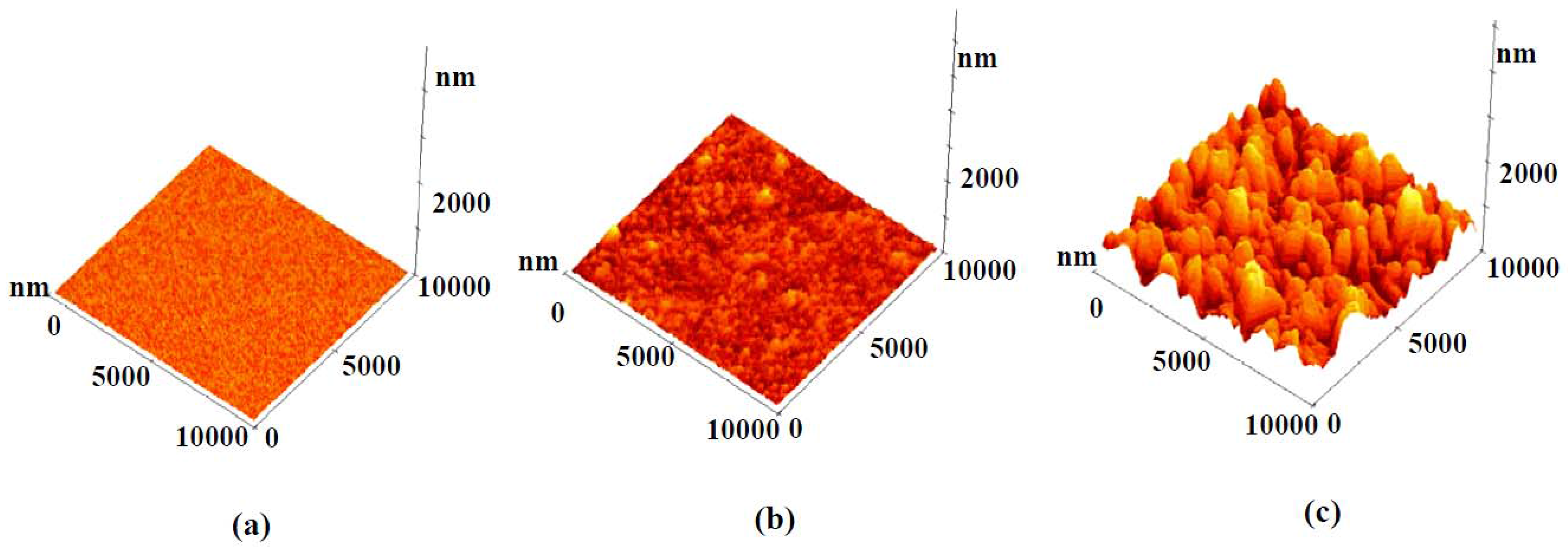
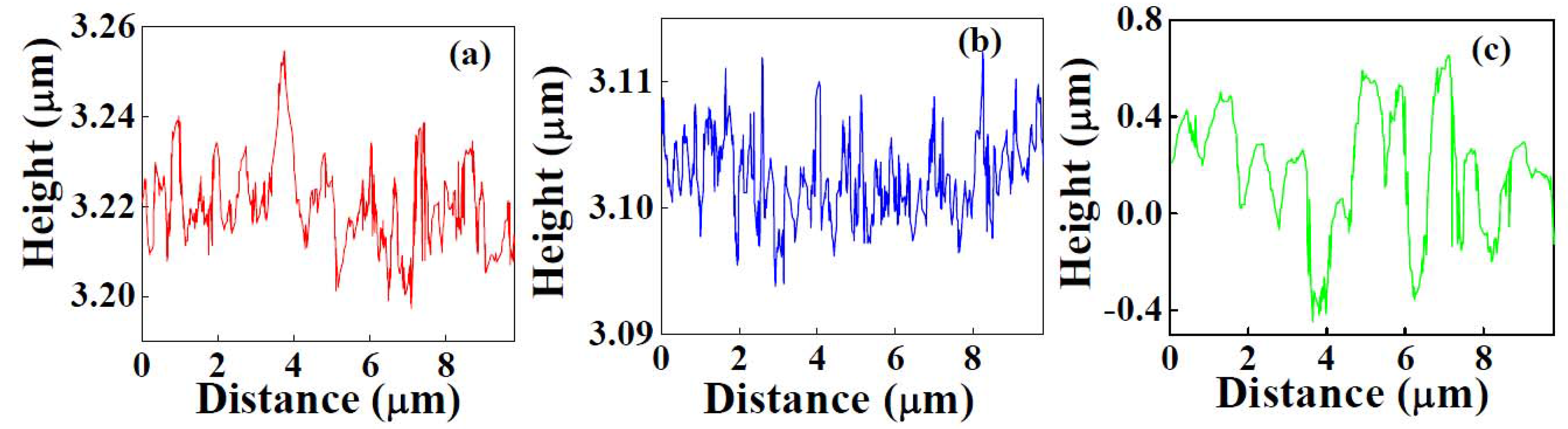
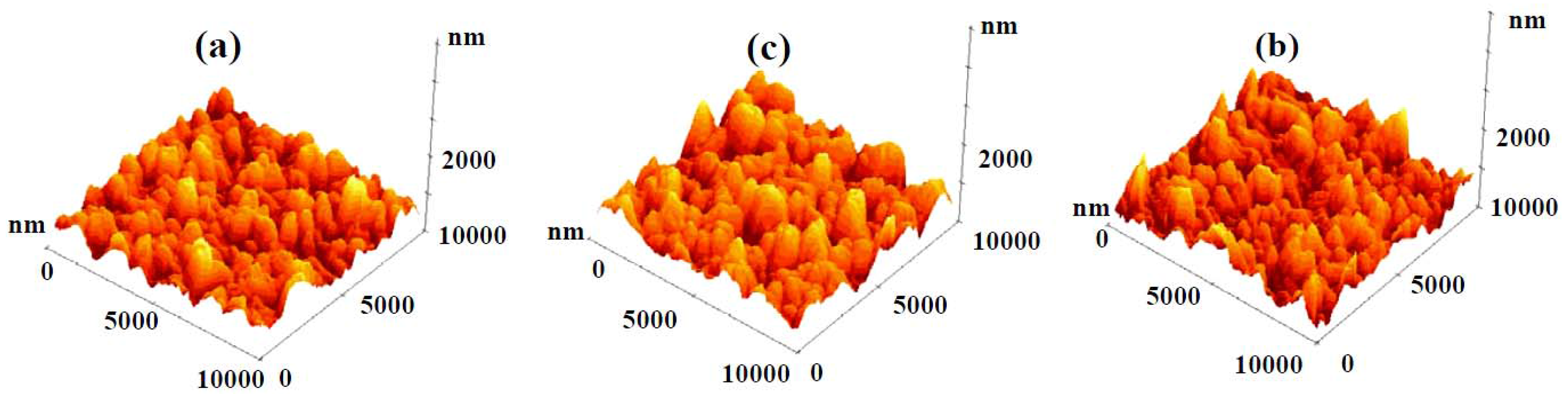
3.1. Structure and Morphology

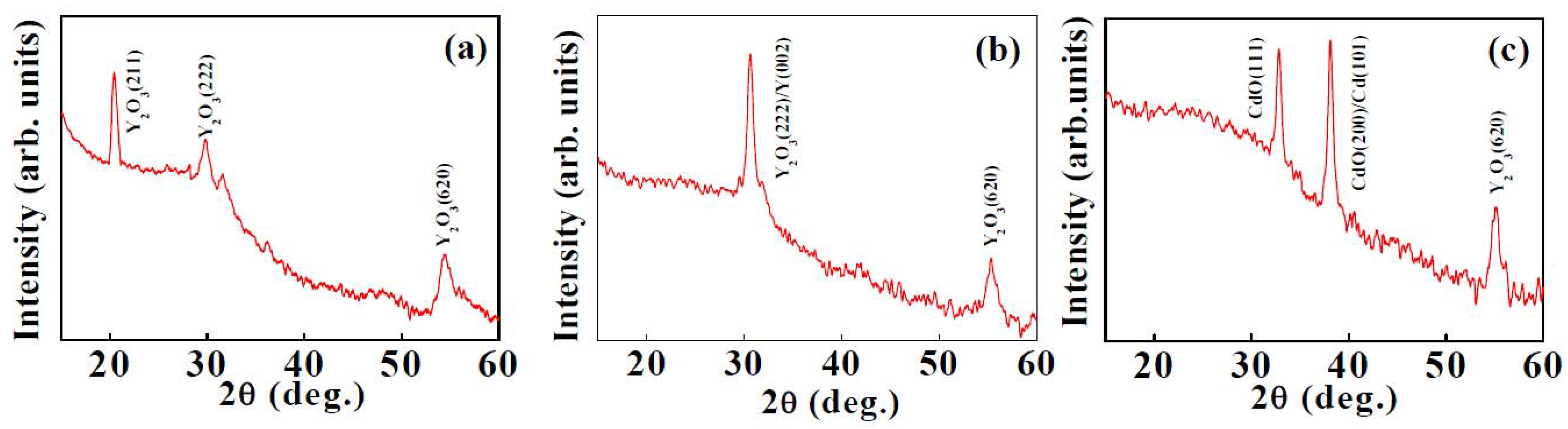
3.1.1. X-ray Diffraction

Figure 1(a–c) shows the XRD plots of sputter deposited Y2O3, thermally oxidized Y-Y2O3 and Cd-CdO template assisted Y2O3 coatings. Reactively sputtered coatings (Figure 1(a)) showed reflections corresponding to (211), (222) and (620) of cubic Y2O3 (JCPDS card no. 025–1200). Figure 1(b) shows XRD pattern for thermally oxidized Y-Y2O3 coating. Two peaks are observed at 2θ = 30.7° and 55.3°, which correspond to (222) and (620) planes of cubic Y2O3,respectively (JCPDS card no. 025–1200). The peak centered at 2θ = 30.7° corresponds to (002) plane of hexagonal yttrium (JCPDS card no. 12–702). The presence of diffraction peaks from Y and Y2O3 show that only the top surface layer of the coating is oxidized. The XRD plot for Cd-CdO template assisted Y2O3 coating is shown in Figure 1(c). The peak observed at 2θ = 55.3° corresponds to the (620) plane of Y2O3. Two additional peaks are also observed at 2θ = 32.9° and 38.1°, which are attributed to the (111) and (200) planes of cubic CdO, respectively (JCPDS card no. 5–0640). The peak centered at 2θ = 38.1° corresponds to (101) plane of metallic hexagonal Cd (JCPDS card no. 5–0674). The diffraction peaks for Cd and CdO are from the template. Here we observed diffraction peaks for both Cd and CdO, which indicates that only the uppermost surface layer of the coating is oxidized, as the Cd-CdO template is prepared by sputtering followed by thermal oxidation. The average grain size of Y2O3 coatings was calculated from the prominent peaks using Scherrer’s formula. The average grain sizes for sputtered deposited Y2O3, thermally oxidized Y-Y2O3 and template assisted Y2O3 coatings were 15.0 nm, 15.5 nm and 19.5 nm, respectively.
Figure 1. X-ray diffraction plots of: (a) sputter deposited Y2O3 coating, (b) thermally oxidized Y-Y2O3coating, and (c) template assisted Y2O3 coating.
Nanomaterials 02 00065 g001

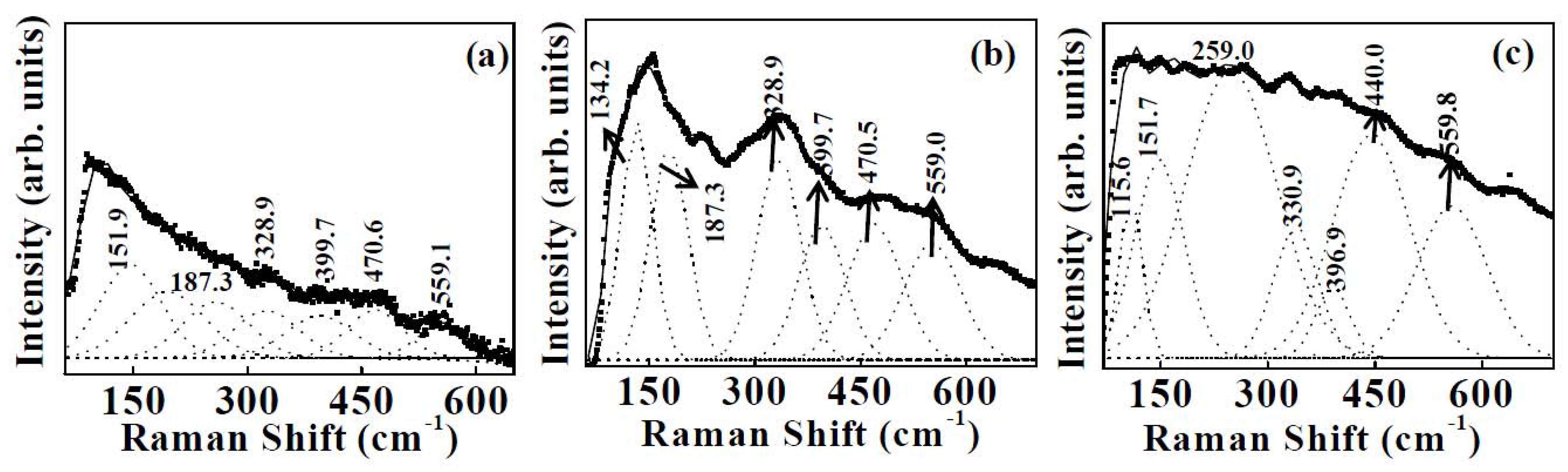
3.1.2. Micro-Raman Spectroscopy

The chemical structure of the coating was studied by micro-Raman spectroscopy (Figure 2). Yttrium sesquioxide crystallizes in the cubic system and is a body centered cubic with space group Ia3 (Z = 16). The structure is related to the structure of fluorite, with each yttrium ion located at the center of the cube from which two of the eight neighboring oxygens of the fluoride have been removed. As the structure is body centered, the unit cell contains the primitive cell twice. The latter cells, containing eight formula units, were used for the theoretical numbering of vibration. The irreducible representations for optical and acoustical modes are [40,41]:
Гop = 4 Ag + 4 Eg+ 14 Fg+ 5 A2u + 5 Eu+ 16 Fu
Гac = Fu,
where Ag, Eg and Fg are Raman active, Fu is infrared (IR) active and A2u and Eu are inactive. Twenty two Raman lines of Ag, Eg and Fg modes and sixteen Fu IR bonds are then predicted. Figure 2(a–c) shows the Raman spectra of Samples 1–3. The frequencies of various Raman bands were determined using deconvolution of the Raman data by Gaussian fit as shown in Figure 2. The assignment of the Raman spectrum of cubic Y2O3 for Samples 1–3 is given in Table 1. The Raman spectrum of Sample 1 (Figure 2(a)) showed six peaks at 151.9, 187.3, 328.9, 399.7, 470.6 and 559.1 cm−1 [40,41]. The peaks observed at 187.3, 328.9 and 559.1 cm−1 are attributed to the Fg+ Eg mode of Y2O3 [40,41]. The peak centered at 399.7 cm−1 corresponds to Fg and at 151.9, 470.6 cm−1 correspond to Fg + Ag modes of Y2O3[40,41]. For Sample 2, the Raman peaks observed at 134.2 and 399.7 cm−1 are attributed to Fg, 187.3, 328.9 and 559.0 cm−1 are attributed to Fg + Eg, and 470.6 cm−1 is attributed to Fg + Ag modes of cubic Y2O3 (Figure 2(b)) [40,41]. The Raman spectrum of template assisted Y2O3 coating (Sample 3) is shown in Figure 2(c). In addition to the above modes we observed a few additional peaks at 115.6, 440.0 and 559.8 cm−1. The peaks centered at 115.6 and 396.9 cm−1 are attributed to Fg + Ag and Fg modes of Y2O3, respectively. The peaks observed at 440.0 and 559.8 cm−1 correspond to Fg+ Eg mode of Y2O3 [40,41]. For Sample 3 an additional peak is observed at 259.0 cm−1, which corresponds to CdO. This peak is from the Cd-CdO template.
Figure 2. Deconvoluted Raman spectra of: (a) sputter deposited Y2O3 coating, (b) thermally oxidized Y-Y2O3 coating, and (c) template assisted Y2O3 coating.
Nanomaterials 02 00065 g002
Table 1. The assignment of Raman spectra of for reactively sputtered Y2O3, thermally oxidized Y-Y2O3 and template assisted Y2O3 coatings.
Sample 1Sample 2Sample 3
Peak position (cm−1)SymmetryPeak position (cm−1)SymmetryPeak position (cm−1)Symmetry
151.9Fg+ Ag134.2Fg115.6Fg
187.3Fg+ Eg187.3Fg+ Eg151.7Fg+ Ag
328.9Fg+ Eg328.9Fg+ Eg330.9Fg+ Eg
399.7Fg399.7Fg396.9Fg
470.6Fg+ Ag470.5Fg+ Ag440.0Fg+ Eg
559.1Fg+ Eg559.0Fg+ Eg559.8Fg+ Eg

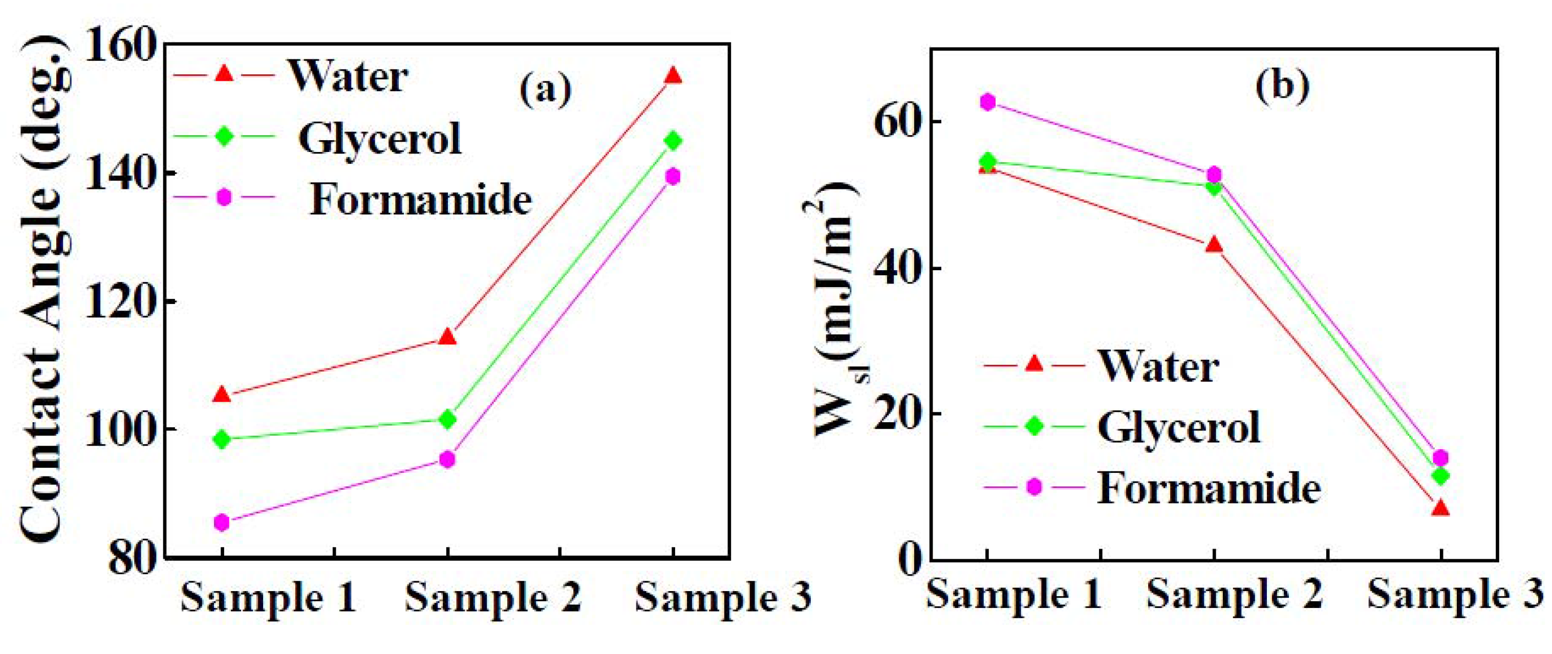
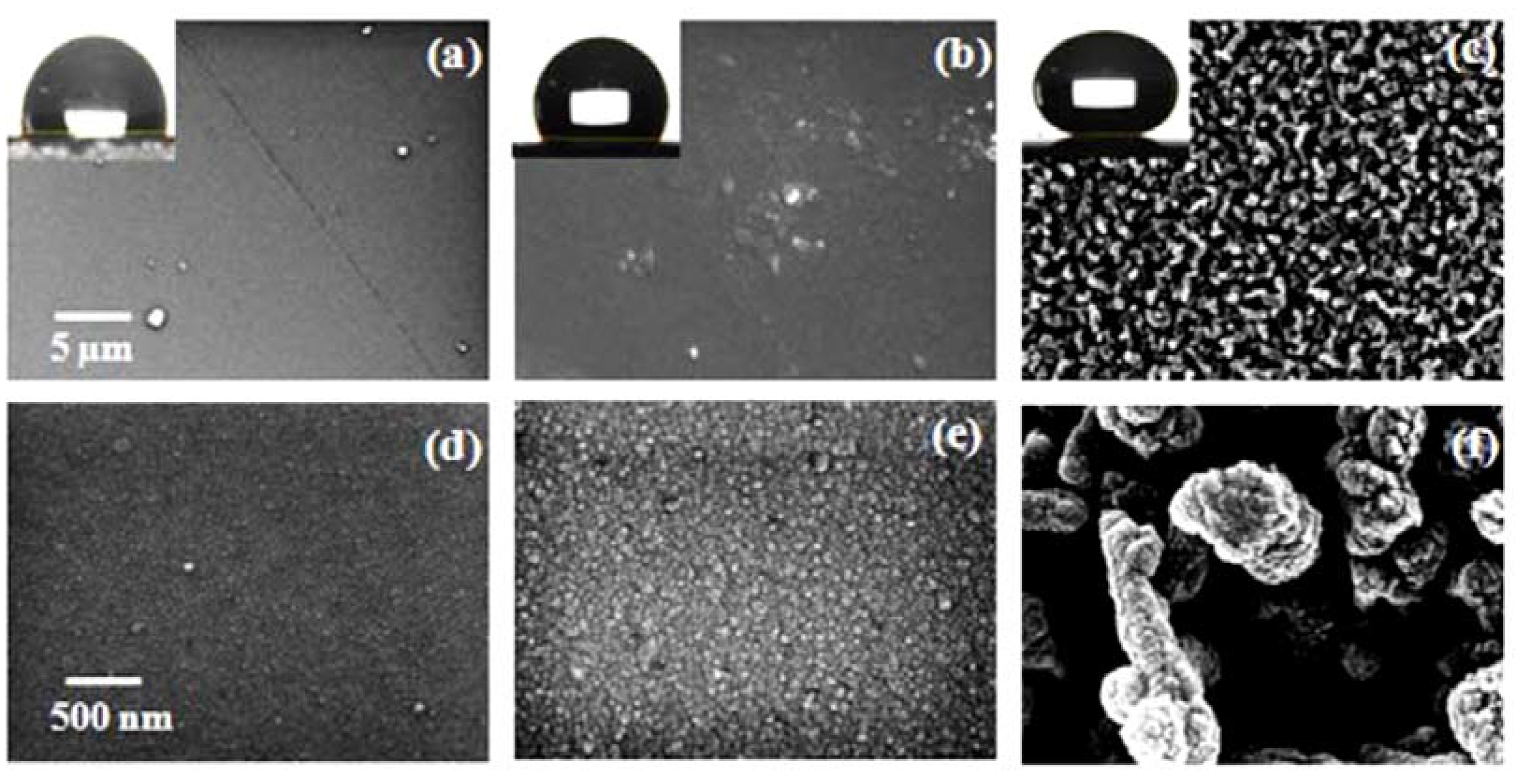
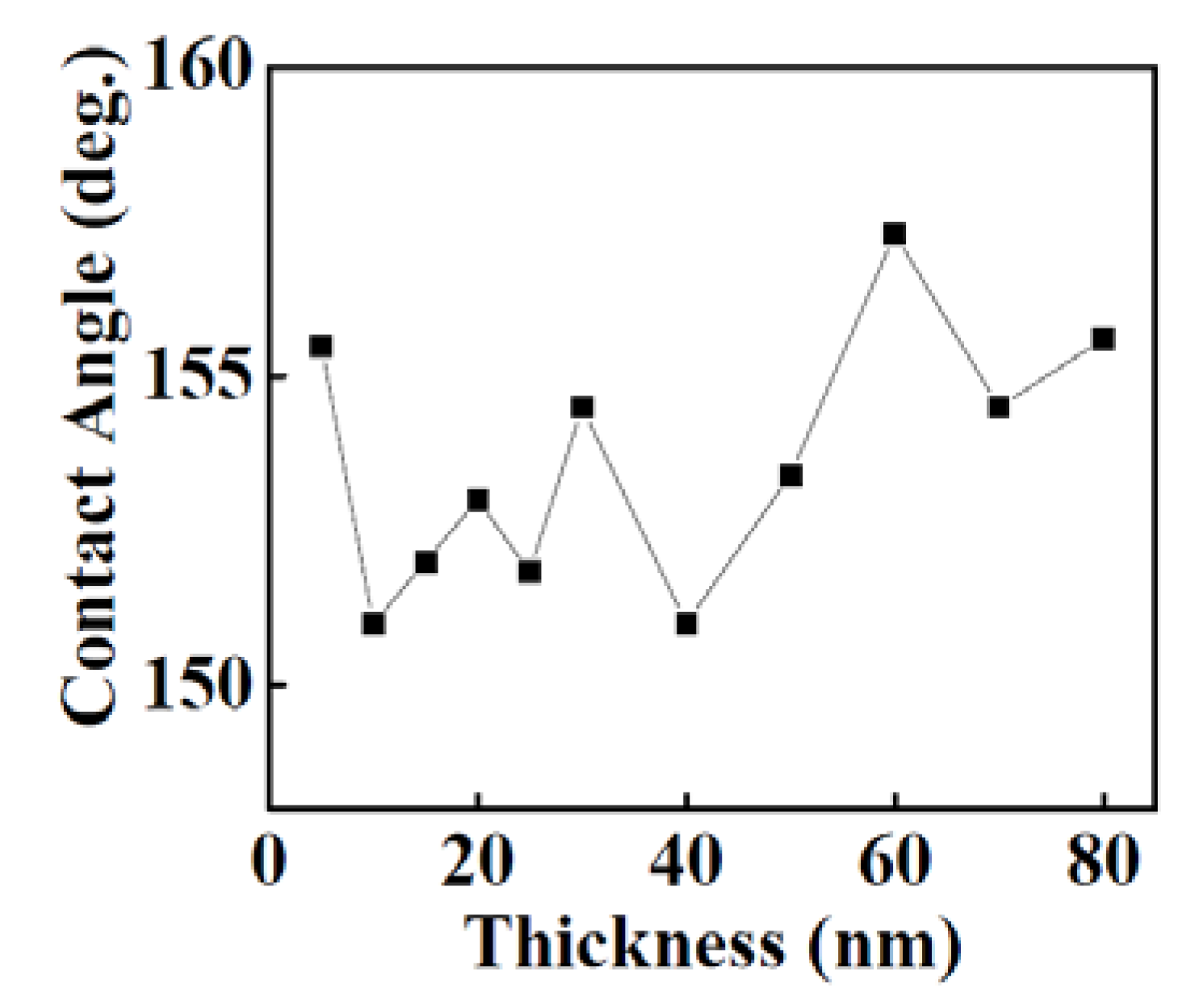
3.1.3. Wettability of Y2O3 Coatings

Sputter deposited Y2O3, thermally oxidized Y-Y2O3 and template assisted Y2O3 coatings show different surface morphologies. The surface morphologies of Samples 1–3 were examined by FESEM and are shown in Figure 3(a–f) at two different magnifications. The water contact angles for Samples 1, 2 and 3 were 99°, 117° and 155°, respectively as shown in the insets in Figure 3(a–c). The dynamic contact angle measurements for Sample 3 showed an advancing water contact angle of 154° and a receding water contact angle of 144° with a contact angle hysteresis of 8° (data not shown). The relatively low contact angle of the sputter deposited Y2O3 and thermally oxidized Y-Y2O3 coatings compared to the template assisted Y2O3 coating is attributed to a densely packed nano-grain like microstructure without any void space (shown in Figure 3(a,b) and Figure 3(d,e) at lower and higher magnifications, respectively). The sputter deposited and thermally oxidized Y2O3 coatings show hydrophobicity with an ultralow surface roughness (discussed later). It is well known that, improving the surface roughness is a crucial factor for the fabrication of a superhydrophobic surface [42]. To improve the surface roughness a new process was applied. The Cd-CdO template was prepared with a high average surface roughness (Ra = approximately 178 nm, data not presented) and shows superhydrophobic nature (water contact angle > 150°). A thin film of Y2O3 is deposited on the Cd-CdO template which enhanced the surface roughness, resulting in the superhydrophobicity. The surface morphology of the template assisted Y2O3 coating is shown in Figure 3(c,f) at low and high magnifications, respectively.
Figure 3. Field emission scanning electron microscopy images of: (a) sputter deposited Y2O3 coating, (b) thermally oxidized Y-Y2O3 coating, and (c) template assisted Y2O3 coating at low magnification with the corresponding optical photographs of water droplet contact angle shown in the inset. High magnification images are shown in (d–f), respectively.
Nanomaterials 02 00065 g003
In order to further confirm the microstructure of these samples the FESEM data was also recorded at higher magnification, which showed a nanograin-like microstructure for sputtered deposited Y2O3 (Figure 3(d)), thermally oxidized Y-Y2O3 (Figure 3(e)) and non-uniform nanostructures for the template assisted Y2O3 coating (Figure 3(f)). The low resolution image (Figure 3(c)) shows the presence of solid components (i.e., whitish regions) and air pockets (i.e., darker regions). This combination of air gaps and solid regions behaves as the first or higher scale roughness of the coating as shown in the roughness profile presented later. Even though the air pockets are in sub-micron range, the roughness (that is, average height of hills and valleys) was in the nanometric scale. The high magnification (Figure 3(f)) showed the solid surface to consist of fused individual structures which generated a textured or a patterned surface. The textured surface acts as the second or lower scale roughness (believed to be a few tens of nanometers). This texturing gives rise to a multi-scale roughness in the Y2O3 coating deposited on the Cd-CdO template, which was responsible for the observed superhydrophobicity. According to the Cassie-Baxter model, the surface fraction of the solid (f1) and air pockets (f2) impacts the water contact angle for a composite surface which can be calculated by Equation 3. The air fractions for Samples 2 and 3 were 0.32 and 0.91, respectively (assuming Sample 1 with an average roughness 3 nm as a smooth surface and contact angle for Sample 1 = 99°). The surface roughness of as-deposited Y2O3 coatings was measured by AFM. Figure 4(a–c) shows the AFM images of sputter deposited Y2O3, thermally oxidized Y-Y2O3 coating and template assisted Y2O3 coating and the corresponding 2D roughness profiles are shown in Figure 5(a–c). The values of average surface roughness of sputter deposited Y2O3, thermally oxidized Y2O3 and template assisted Y2O3 coatings are: 3, 11 and 180 nm, respectively. The AFM data confirms the presence of nanoscale surface roughness. The presence of air-pockets in Sample 3 was confirmed by FESEM as shown in Figure 3(c), which contributes to the higher scale of roughness. The variation of the water contact angle with the template assisted Y2O3 coating thickness is shown in Figure 6. It is clearly seen that irrespective of the change in the thickness of the coating, the contact angle always remains greater than 150°. To cross check this observation, the surface roughness of the coatings was measured by AFM. The AFM images of the template assisted Y2O3 coating for different thicknesses are shown in Figure 7(a–c). The average surface roughness values for 30, 60 and 80 nm thickness of template assisted Y2O3 coatings are approximately 180, 185 and 188 nm, respectively. The Y2O3 coating follows the template/substrate morphology. It can be concluded that for coatings with different thicknesses of Y2O3, the change in the average surface roughness was negligible, which is responsible for superhydrophobicity for all thicknesses.
Figure 4. 3D atomic force microscopy (AFM) images of: (a) sputter deposited Y2O3 coating, (b) thermally oxidized Y-Y2O3 coating, and (c) template assisted Y2O3 coating.
Nanomaterials 02 00065 g004
Figure 5. Surface roughness profiles of: (a) sputter deposited Y2O3 coating, (b) thermally oxidized Y-Y2O3 coating, and (c) template assisted Y2O3 coating.
Nanomaterials 02 00065 g005
Figure 6. Variation of contact angle of Cd-CdO template assisted Y2O3 coating with thickness of Y2O3 layer.
Nanomaterials 02 00065 g006
Figure 7. AFM images of template assisted Y2O3 coating at different thicknesses of Y2O3 layer: (a) 30 nm, (b) 60 nm, and (c) 80 nm.
Nanomaterials 02 00065 g007
The contact angle and work of adhesion of the polar liquids for Samples 1–3 are shown in Figure 8(a,b), respectively as per the procedure described elsewhere [43]. Ideally the static CAs of the sample should be found experimentally using a series of probe liquids, with a balanced composition of polar and non-polar components. A suggested series of probe liquids that are easily available and cover the whole range of surface tension values are, polar protic–water, glycerol, formamide and aniline, and non-polar aprotic–diiodomethane, dodecane, hexadecane, ethylene glycol and benzene. In the present work we chose only three liquids for the initial estimate of the free surface energy of the samples. The dispersive and polar components of glycerol, formamide and water are reported in Reference 44. The static contact angles for Samples 1–3 for different probe liquids are presented in Table 2. Compared to non-polar liquids, the polar liquids interact differently with Y2O3 coatings because they exhibit a large dipole moment and have a strong tendency for hydrogen bonding. The contact angle of liquids (water, formamide and glycerol) for Samples 1–3 increased in the following order: θformamideθglycerolθwater. The free energies of the liquid-solid, solid-vapor and liquid-vapor interfaces are dependent on the work of adhesion at the solid-liquid interface. The work of adhesion for Samples 1–3 is calculated, without taking into account the polar/apolar interactions by the Young-Dupre Equation [45]:
(4)
The work of adhesion of water for Samples 1–3 were 54, 43 and 7 mJ/m2, respectively. It can be clearly seen that the work of adhesion for Sample 3 was very low compared to Samples 1 and 2. This is because the template assisted Y2O3 coating demonstrated a composite surface (Cassie Baxter state), which contains a void space filled with air combined with nonuniform nanostructures (shown in Figure 3(c)). This composite interface decreases the solid-liquid contact area and therefore decreases the work of adhesion. These results show that the presence of a micron scale void space combined with non-uniform nanostructures like morphology is responsible for superhydrophobicity in Sample 3.
Figure 8. Variations of: (a) contact angle and (b) work of adhesion of the polar liquids for Samples 1–3.
Nanomaterials 02 00065 g008
Table 2. Static contact angles of the probe liquids for reactively sputtered Y2O3, thermally oxidized Y-Y2O3 and Cd-CdO template assisted Y2O3 coatings.
SampleStatic contact angle (degree)
WaterGlycerolFormamide
Sample 1999885
Sample 211710195
Sample 3155145139

4. Conclusions

The water contact angles were 99°, 117° and 155° respectively for reactively sputtered Y2O3, thermally oxidized Y-Y2O3 and the Cd-CdO template assisted Y2O3 coating. Superhydrophobicity was demonstrated by the template assisted Y2O3 coating and it was attributed to an optimum combination of non-uniform nanostructures and a void space which gives rise to a high surface roughness. The work of adhesion was calculated for different probe liquids (water, glycerol and formamide). The work of adhesion for all three liquids was very low for the Cd-CdO template assisted Y2O3 coating when compared to the reactively sputtered Y2O3 coating and the thermally oxidized Y-Y2O3 coating. The superhydrophobic properties of the the Cd-CdO template assisted Y2O3 coating are attributed to a non-uniform nanostructure like morphology combined with a micron scale void space filled with air. The water droplet on such a coating is in contact with a comparatively higher fraction of air gaps, than the rough surface which results in a higher contact angle. The surface roughness of reactively sputtered Y2O3 (3 nm), thermally oxidized Y-Y2O3 (11 nm) and the Cd-CdO template assisted Y2O3 coating (180 nm) was determined by AFM. The reactively sputtered Y2O3 and thermally oxidized Y-Y2O3 coatings demonstrate hydrophobicity with a very low surface roughness. The surface roughness of the Y2O3 coating was improved by using a Cd-CdO template, which resulted in superhydrophobicity.

Acknowledgements

We thank the Director, NAL (CSIR) for giving permission to publish these results. Work presented in the manuscript is partially supported by CSIR under Grant No. FAC-00-01-11. Authors thank Nagaraj Selvakumar and Siju John for their help in the measurements of contact angles and FESEM data.

References

  1. Wenzel, R.N. Resistance of solid surfaces to wetting by water. Ind. Eng. Chem. 1936, 28, 988–994. [Google Scholar] [CrossRef]
  2. Baxter, S.; Cassie, A.B.D. Wettability of porous surfaces. Trans. Faraday Soc. 1944, 40, 546–551. [Google Scholar] [CrossRef]
  3. Chatelain, F.; Delapierre, G.; Obeid, P.; Pegon, P.; Getin, S.; Brachet, A.G.; Fouque, B. Improvement of yeast biochip sensitivity using multilayer inorganic sol-gel substrates. Biosens. Bioelectron. 2007, 22, 2151–2157. [Google Scholar] [CrossRef] [PubMed]
  4. Galvin, P.; Wood, T.; Rawely, O.; Moore, E. Monitoring of cell growth in vitro using biochips packaged with indium tin oxide sensors. Sens. Actuator. B Chem. 2009, 139, 187–193. [Google Scholar] [CrossRef]
  5. Ohab, M.; Gotou, T.; Hirata, M. Thin-film particles of graphite oxide. 2: Preliminary studies for internal micro fabrication of single particle and carbonaceous electronic circuits. Carbon 2005, 43, 503–510. [Google Scholar] [CrossRef]
  6. Wang, M.; Han, S.; Peng, R.; Guo, Y.; Geng, H. A facile route for preparation of conjugated polymer functionalized inorganic semiconductors and direct application in hybrid photovoltaic devices. Solar Energy Mater. Solar Cells 2010, 94, 1293–1299. [Google Scholar] [CrossRef]
  7. Passacantando, M.; Santucci, S.; Cantalini, C.; Sberveglieri, G.; Comini, E.; Wlodarski, W.; Li, Y.X.; Galatsis, K. Comparison of single and binary oxide MoO3, TiO2 and WO3 sol-gel sensors. Sens. Actuator. B Chem. 2002, 83, 276–280. [Google Scholar] [CrossRef]
  8. Lamdhade, G.T.; Yawale, S.S.; Yawale, S.P. Tin oxide and zinc oxide based doped humidity sensors. Sens. Actuator. A 2007, 135, 388–393. [Google Scholar] [CrossRef]
  9. Li, H.D.; Sun, X.D.; Wu, X.H.; Ma, C.L.; Wang, Y.D. Electrical and gas-sensing properties of mesostructured tin oxide-based H2 sensors. Sens. Actuator. B Chem. 2002, 85, 270–276. [Google Scholar] [CrossRef]
  10. Akins, D.L.; Stevens, N. Dye-doped inorganic/organic composite films as fluorescence sensors for methanol vapor. Sens. Actuator. B Chem. 2007, 123, 59–64. [Google Scholar] [CrossRef]
  11. Basu, S.; Saha, H.; Basu, P.K.; Bhattacharyya, P. Fast response methane sensor using nanocrystalline zinc oxide thin films derived by sol–gel method. Sen. Actuator. B Chem. 2007, 124, 62–67. [Google Scholar] [CrossRef]
  12. Yi, J.; Kwak, D.J.; Lim, D.G. Improved interface properties of yttrium oxide buffer layer on silicon substrate for ferroelectric random access memory applications. Thin Solid Films 2002, 422, 150–154. [Google Scholar] [CrossRef]
  13. Shiratori, S.; Fujimoto, K.; Kim, J.; Ogawa, T.; Ding, B. Fabrication of a superhydrophobic nanofibrous zinc oxide film surface by electro-spinning. Thin Solid Films 2008, 516, 2495–2501. [Google Scholar] [CrossRef]
  14. Yan, H.; Song, X.; Zhang, X. H.; Li, E.; Wang, B.; Pei, M. D. The fabrication of superhydrophobic copper films by a low-pressure-oxidation method. Appl. Surf. Sci. 2010, 256, 5824–5827. [Google Scholar] [CrossRef]
  15. Liu, W.; Hao, J.; Zhou, F.; Guo, Z. Stable biomimetic superhydrophobic engineering materials. J. Am. Chem. Soc. 2005, 127, 15670–15671. [Google Scholar] [CrossRef] [PubMed]
  16. Gogolides, E.; Tserepi, A.; Papageorgiou, D.; Tsougeni, K. “Smart” polymeric microfluidics fabricated by plasma processing: Controlled wetting, capillary filling and hydrophobic valving. Lab Chip 2010, 10, 462–469. [Google Scholar] [CrossRef] [PubMed]
  17. Jiang, L.; Zhai, J.; Feng, X. The fabrication and switchable superhydrophobicity of TiO2 nanorod films. Angew. Chem. Int. Ed. 2005, 44, 5115–5118. [Google Scholar] [CrossRef]
  18. Nistchke, M.; Motornov, M.; Muller, M.; Minko, S. Two-level structured self-adaptive surfaces with reversibly tunable properties. J. Am. Chem. Soc. 2003, 125, 3896–3900. [Google Scholar] [CrossRef] [PubMed]
  19. Jiang, L.; Gao, X.; Feng, L.; Sun, T. Bio-inspired surfaces with special wettability. Acc. Chem. Res. 2005, 38, 644–652. [Google Scholar] [CrossRef] [PubMed]
  20. Jiang, L.; Yao, J.; Feng, X.; Wang, S. Controlling wettability and photochromism in a dual-responsive tungsten oxide film. Angew. Chem. Int. Ed. 2006, 45, 1264–1267. [Google Scholar] [CrossRef]
  21. Lkkala, O.; Ras, R.H.A.; Ritala, M.; Lindstrom, T.; Ankerfors, M.; Kemell, M.; Pore, V.; Sainio, J.; Ruokolainen, J.; Nykanen, A.; Houbenov, N.; Silvennoinen, R.J.; Kettunen, M. Photoswitchable superabsorbency based on nanocellulose aerogels. Adv. Funct. Mater. 2011, 21, 510–517. [Google Scholar] [CrossRef]
  22. Ras, R.H.; Karppinen, M.; Sahramo, E.; Malm, J. A photo-controlled wettability switching by conformal coating of nanoscale topographies with ultrathin oxide films. Chem. Mater. 2010, 22, 3349–3352. [Google Scholar] [CrossRef]
  23. Popov, D.; Thielsch, R.; Atanassov, G. Optical properties of TiO2, Y2O3, and CeO2 thin films deposited by electron beam evaporation. Thin Solid Films 1993, 223, 288–292. [Google Scholar] [CrossRef]
  24. Perriere, J.; Pailloux, F.; Gaboriaud, R.J. Pulsed laser deposition of Y2O3 thin film on MgO. Appl. Surf. Sci. 2002, 186, 477–482. [Google Scholar] [CrossRef]
  25. Kennedy, I.M.; Guo, B.; Dosev, D. Photoluminescence of Eu3 + : Y2O3 as an indication of crystal structure and particle size in nanoparticles synthesized by flame spray pyrolysis. J. Aerosol Sci. 2006, 37, 402–412. [Google Scholar] [CrossRef]
  26. Garcia, M.; Guasti, M.F.; Diamant, R.; Poniatowski, E.H.; Alonso, J.C. Photoluminescent thin films of terbium chloride-doped yttrium oxide deposited by the pulsed laser ablation technique. Thin Solid Films 1997, 303, 76–83. [Google Scholar] [CrossRef]
  27. Bose, A.C.; Joseyphus, R.J.; Elanchezhiyan, J.; Yogamalar, N.R.; Srinivasan, R. Structural and optical properties of europium doped yttrium oxide nanoparticles for phosphor applications. J. Alloys Compd. 2010, 496, 472–477. [Google Scholar] [CrossRef]
  28. Srikumar, S.R.; Mahalingam, T.; Auluck, S. Controlled synthesis, optical and electronic properties of Eu3+ doped yttrium oxysulfide (Y2O2S) nanostructures. J. Colloid Interface Sci. 2009, 336, 889–897. [Google Scholar] [CrossRef] [PubMed]
  29. Mugnier, J.; Garapon, C.; Perriere, J.; Millon, E.; Viana, B.; Aschehoug, P.; Fidancev, E.A.; Huignard, A.; Moll, O.P.Y. Eu3+and Tm3+ doped yttrium oxide thin films for optical applications. J. Luminesc 2000, 87–89. [Google Scholar]
  30. Fu, L.; Tanner, P.A. Morphology of Y2O3: Eu3+ prepared by hydrothermal synthesis. Chem. Phys. Lett. 2009, 470, 75–79. [Google Scholar] [CrossRef]
  31. Muroga, T.; Terai, T.; Koch, F.; Maier, H.; Suzuki, A.; Sawada, A. Fabrication of yttrium oxide and erbium oxide coatings by PVD methods. Fusion Eng. Des. 2005, 75, 737–740. [Google Scholar] [CrossRef]
  32. Xianping, F.; Pengyue, Z.; Shizhu, Z.; Zhanglian, H.; Huang, G. Synthesis of yttrium oxide nanocrystal via solvothermal process. J. Rare Earths 2006, 24, 47–50. [Google Scholar] [CrossRef]
  33. Tudoran, L.B.; Grecu, R.; Popovici, E.J.; Muresan, L. Studies on the synthesis of europium activated yttrium oxide by wet-chemical method: 1. Influence of precursor quality on phosphor photoluminescence properties. J. Alloys Compd. 2009, 471, 421–427. [Google Scholar] [CrossRef]
  34. Paumier, F.; Guerin, P.; Pailloux, F.; Gaboriaud, R.J. Yttrium oxide thin films, Y2O3, grown by ion beam sputtering on Si. J. Phys. D Appl. Phys. 2000, 33, 2884–2889. [Google Scholar] [CrossRef]
  35. Shih, I.; Yip, L.S. Studies of yttrium oxide films prepared by magnetron sputtering. Electron. Lett. 1988, 24, 1287–1288. [Google Scholar] [CrossRef]
  36. Dai, B.; Lei, P.; Tian, G.; Han, J.; Weng, Y.; Shen, W.; Zhu, Y.; Zhu, J. Growth and characterization of yttrium oxide films by reactive magnetron sputtering. Thin Solid Films 2011, 519, 4894–4898. [Google Scholar] [CrossRef]
  37. Qian, Y.; Liu, X.; Zhang, S.; Li, S.; Liu, Z.; Tang, Q. Synthesis of yttrium hydroxide and nanotubes. J. Cryst. Growth 2003, 259, 208–214. [Google Scholar] [CrossRef]
  38. Pengyue, Z.; Lixia, P.; Qichao, Z.; Zhanglian, H.; Zhenxiu, X. Preparation and luminescence properties of Y2O3: Eu3+ nanorods via post annealing process. J. Rare Earths 2006, 24, 111–114. [Google Scholar] [CrossRef]
  39. Rajam, K.S.; Barshilia, H.C. Sputter deposited nanometric multi-scale rough Cd-CdO superhydrophobic thin films. Nanosci. Nanotechnol. Lett. 2011, 3, 300–305. [Google Scholar] [CrossRef]
  40. Beny, J.M.; Husson, E.; Proust, C.; Repelin, Y. Vibrational spectroscopy of the C-form of yttrium sesquioxide. J. Solid State Chem. 1995, 118, 163–169. [Google Scholar] [CrossRef]
  41. Yoshimura, M.; Kakihana, M.; Lee, J.H.; Yashima, M. Raman spectral characterization of existing phase in the Y2O3-Nb2O5 system. J. Phys. Chem. Solids 1997, 58, 1593–1597. [Google Scholar] [CrossRef]
  42. Yalamanchili, M.R.; Drelich, J.; Veeramasuneni, S.; Miller, J.D. Effect of roughness determined by atomic force microscopy on the wetting properties of PTFE thin films. Polym. Eng. Sci. 1996, 36, 1849–1855. [Google Scholar] [CrossRef]
  43. Rajam, K.S.; Devi, L.M.; Pillai, N.; Selvakumar, N.; Barshilia, H.C. Wettability of ZnO: A comparison of reactively sputtered; thermally oxidized and vacuum annealed coating. Appl. Surf. Sci. 2011, 257, 4410–4417. [Google Scholar] [CrossRef]
  44. Rajam, K.S.; Barshilia, H.C.; Selvakumar, N. Effect of substrate roughness on the surface free energy of sputter deposited superhydrophobic polytetrafluoroethylene coatings: A comparison of experimental data with different theoretical models. J. Appl. Phys. 2010, 108, 013505:1–013505:9. [Google Scholar]
  45. Cazin, A.A.; Arnthal, M.; Zeuner, G. Theorie Mechanique De La Chaleur, Avec Ses Applications Aux Machines; 1869; pp. 1828–1907. Gauthier-Villars: Paris, France. [Google Scholar]

