Article

Ni Supported on Hollow CeO2 Microspheres with Controllable Shell Thickness for Catalytic Dry Reforming of Methane


1
Institute of Materials for Energy and Environment, College of Materials Science and Engineering, Qingdao University, Qingdao 266071, China
2
Faculty of Chemical Engineering and Energy Technology, Shanghai Institute of Technology, Shanghai 201418, China
*
Author to whom correspondence should be addressed.
Nanomaterials 2026, 16(14), 868; https://doi.org/10.3390/nano16140868
Submission received: 22 June 2026 / Revised: 12 July 2026 / Accepted: 13 July 2026 / Published: 15 July 2026
(This article belongs to the Section Environmental Nanoscience and Nanotechnology)

Abstract

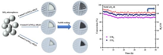
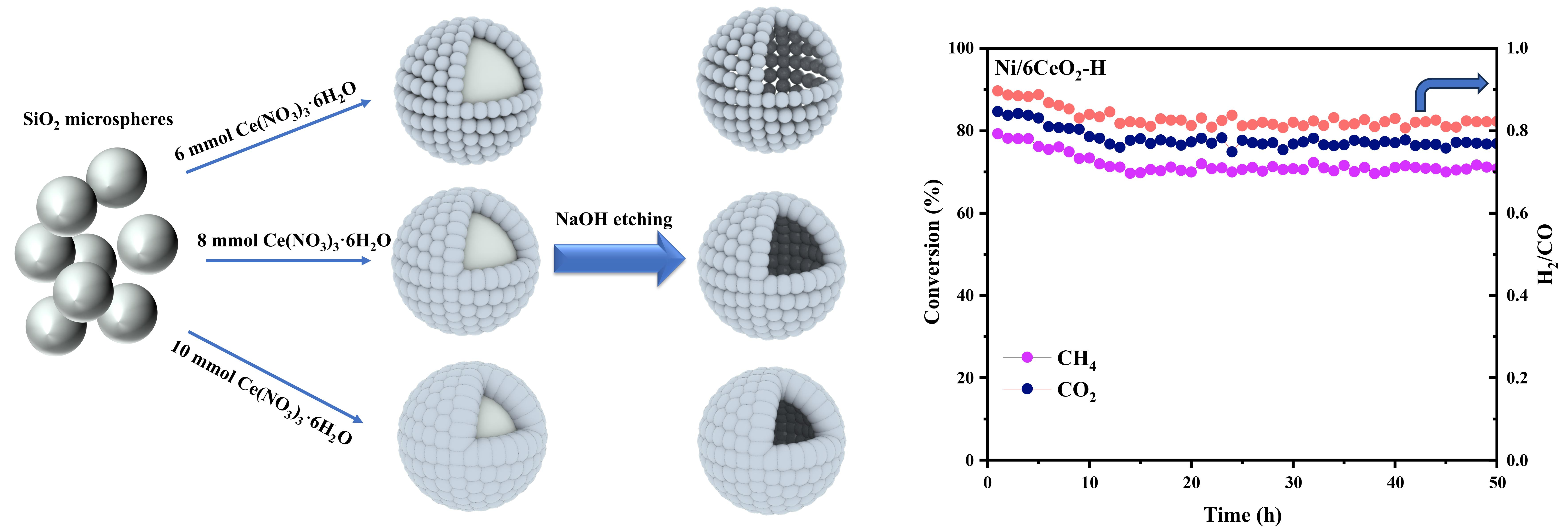
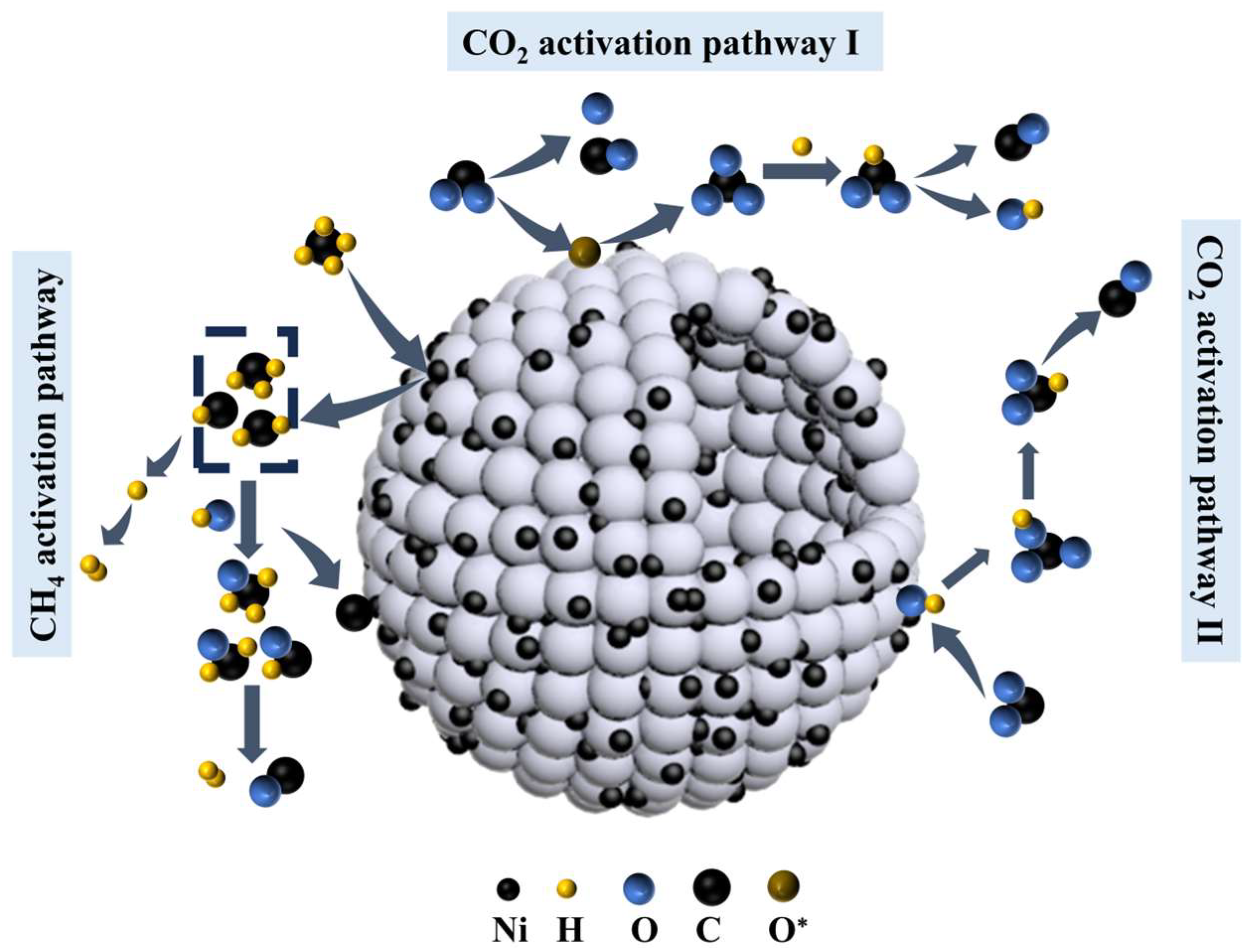
CeO2 hollow nanospheres were fabricated through a hard template-assisted route, with the shell thickness precisely tuned by varying the usage amount of Ce(NO3)3·6H2O. Ni was subsequently deposited onto the xCeO2-H (x = 6, 8, 10) supports via an incipient wetness impregnation method, affording Ni/6CeO2-H, Ni/8CeO2-H, and Ni/10CeO2-H catalysts, which were evaluated for catalytic dry reforming of methane (DRM). Notably, the Ni/6CeO2-H catalyst delivered stable CH4 and CO2 conversions of 70% and 76%, respectively, with an H2/CO molar ratio of 0.81 over a reaction period of 50 h at 750 °C, demonstrating exceptional catalytic stability. Comprehensive characterization revealed that the Ni/6CeO2-H catalyst featured stronger metal–support interaction (MSI) and abundant basic sites, which synergistically enhanced CO2 adsorption and activation, thereby endowing the catalyst with superior coke resistance. In situ infrared spectroscopy further elucidated the DRM reaction mechanism, revealing that surface –OH groups played a pivotal role in suppressing coke formation and sustaining high reaction efficiency by reacting with carbon precursor species (CHx*).

Graphical Abstract

1. Introduction

The continuous growth of global industrial activities has led to a steady increase in fossil fuel consumption, making greenhouse gas emissions a major cause of environmental problems. Among all anthropogenic radiative forcing factors, carbon dioxide (CO2) and methane (CH4) are the two main contributors to climate change [1,2]. Converting these two gases into high-value products is of great importance for reducing global warming and making better use of carbon resources [3,4]. The dry reforming of methane (DRM) reaction converts CO2 and CH4 directly into syngas (CO + H2) with an H2/CO ratio close to 1:1. Compared with steam reforming and partial oxidation, this ratio is more suitable for downstream Fischer–Tropsch synthesis to produce hydrocarbons and oxygenates [5,6]. Nickel-based catalyst is widely used as the active component for DRM because of its low cost and high activity, making it a good alternative to noble metal catalysts such as platinum (Pt), rhodium (Rh), and ruthenium (Ru) [7,8]. However, nickel-based catalyst has two main drawbacks: Nickel (Ni) particles tend to sinter and agglomerate at high temperatures, and carbon deposition on the surface covers active sites and causes catalyst deactivation. These two problems are the biggest obstacles to the industrial usage of Ni-based catalyst in low-temperature DRM [9,10]. Therefore, developing Ni-based catalyst with low cost, high activity, and strong resistance to carbon deposition is essential for the commercialization of DRM. In recent years, researchers have devoted significant efforts to studying various catalyst design strategies, encompassing diverse metal-support combinations [11,12], unique catalyst structures [13,14], and the rational utilization of noble metals [15,16]. In the research about DRM catalyst, commonly used support materials include silica (SiO2), magnesium oxide (MgO), alumina (Al2O3), and ceria (CeO2). Among them [17], CeO2 is regarded as the most promising support material for Ni-based catalysts due to its rich oxygen vacancies and high oxygen storage capacity, holding the potential to achieve both high activity and high stability in DRM reactions [18,19,20,21]. However, conventional supported catalysts have a large exposed area of active metal particles, making it difficult to effectively suppress Ni sintering and carbon deposition growth at high temperatures. In recent years, researchers have carried out extensive design strategy studies on CeO2 catalysts, covering support morphology control, promoter addition, and loading method optimization. For example, Vasiliades et al. [22] prepared Ni-based catalysts supported on CeO2 nanorods (CeO2-NR) and CeO2 nanopolyhedra (CeO2-NP). Their comparison showed that Ni/CeO2-NR exhibited stronger coke resistance because the CeO2 bulk phase had better oxygen migration ability, which increased the carbon deposition gasification rate during CO formation. Daza et al. [23] modified Ni/Mg–Al catalysts with different Ce contents (0, 1, 3, 5, 10 wt.%), and the results showed that Ce doping could effectively suppress carbon deposition. The catalyst modified with 3 wt.% Ce achieved the highest CH4 and CO2 conversions in the DRM reaction and remained stable for up to 100 h.
Among various structure types, hollow sphere structures have attracted considerable attention due to their high specific surface area and unique confinement effect. Studies have shown that hollow sphere CeO2 has already demonstrated certain advantages in the catalysis field. Xie et al. [24] successfully prepared CeO2 hollow nanospheres (CeO2-HS) via a hydrothermal method for efficient catalytic oxidation of toluene. The excellent performance of the CeO2-HS catalyst was mainly attributed to its unique hollow nanosphere structure, which provided a high specific surface area and large pore volume. The CeO2-HS catalyst effectively promoted the conversion of these intermediates and facilitated the cleavage of the aromatic ring, ultimately achieving complete mineralization of toluene to CO2 and H2O. Zhang et al. [25] prepared a copper-based catalyst (Cu-S-Ce) with highly dispersed Cu on hollow sphere CeO2 (S-Ce) for the reverse water–gas shift (RWGS) reaction. Their experiments proved that S-Ce played a key role in stabilizing Cu nanoparticles. The large void space inside the hollow sphere significantly enhanced mass transfer, increased the concentration of reactants and active sites, and promoted the formation of oxygen vacancies, thus leading to stable conversion of intermediates and the formation of active sites in the RWGS reaction.
However, most studies on hollow sphere catalysts have been limited to preparing structures with a single shell thickness. In this work, hollow sphere CeO2-supported Ni catalysts with different shell thicknesses were prepared by a hydrothermal strategy and an incipient wetness impregnation method, aiming to increase the specific surface area of the CeO2 support and achieve uniform dispersion of Ni particles. The catalytic activity and stability of the catalysts were evaluated through DRM performance tests, and the changes in physicochemical properties before and after the reaction were studied in detail, especially the resistance to coke and metal sintering. In addition, temperature-programmed surface reaction and in situ diffuse reflectance spectroscopy were used to analyze the activation behavior of CH4 and CO2 on the Ni-based catalysts and the possible reaction pathways and mechanism.

2. Materials and Methods

2.1. Catalyst Preparation

SiO2 template microspheres were synthesized by the classic Stöber method. The specific procedure was as follows: Amounts of 92 mL of absolute ethanol, 10 mL of ammonia water, and 5 mL of tetraethyl orthosilicate (TEOS, AR) were sequentially added into a beaker and stirred at room temperature for 4 h. After the reaction, the precipitate was collected by centrifugation, washed several times with deionized water and ethanol, and then dried in an oven at 60 °C for 12 h to obtain SiO2 microspheres.
A total of 0.15 g of the as-prepared SiO2 microspheres was dispersed in 30 mL of absolute ethanol and treated by ultrasonication to obtain a uniform slurry. Meanwhile, cerium nitrate hexahydrate (Ce(NO3)3·6H2O, AR) (4 mmol, 6 mmol, 8 mmol, and 10 mmol) and 0.5 g of urea were dissolved in 40 mL of deionized water, stirred evenly, and then mixed with the SiO2 slurry, followed by ultrasonication for 1 h. The resulting mixture was transferred into a stainless-steel autoclave lined with polytetrafluoroethylene and subjected to a hydrothermal reaction at 160 °C for 8 h. After the autoclave was naturally cooled to room temperature, the solid product was collected by centrifugation, washed several times with deionized water and ethanol, and dried in a vacuum oven at 60 °C for 12 h to obtain the CeO2@SiO2 core–shell precursor. Subsequently, the precursor was placed in a 0.5 M sodium hydroxide (NaOH, AR) solution and etched at 80 °C for 6 h to completely remove the SiO2 template. After etching, the solid was collected by centrifugation, washed repeatedly with deionized water and ethanol until clean, and dried in a vacuum oven (DGG-9036AD (Qingdao Lanten Science and Education Instrument Equipment Co., Ltd., Qingdao, China)) at 60 °C for 12 h. Finally, the product was calcined in a muffle furnace from room temperature to 500 °C at a heating rate of 2 °C min−1 and held for 4 h to obtain a series of hollow CeO2 sphere supports, which were denoted as xCeO2-H (where x represents the millimolar amount of added Ce(NO3)3·6H2O, with values of 6, 8, and 10).
The bulk CeO2 was prepared by a direct calcination of a certain amount of Ce(NO3)3·6H2O at 500 °C for 5 h, which was labeled as CeO2.
The Ni/xCeO2-H series and Ni/CeO2 catalysts were prepared by an incipient wetness impregnation method. The specific procedure was as follows: an appropriate amount of nickel nitrate (Ni(NO3)2·6H2O, AR) was dissolved in a certain volume of deionized water to prepare an impregnation solution. Then, 1.00 g of support was added, and the mixture was treated by ultrasonication to achieve uniform dispersion. The resulting mixture was dried in an oven at 60 °C for 12 h, then transferred to a muffle furnace and calcined from room temperature to 500 °C at a heating rate of 2 °C min−1 for 4 h. The target Ni-loaded hollow CeO2 microsphere catalysts were finally obtained, denoted as Ni/6CeO2-H, Ni/8CeO2-H, Ni/10CeO2-H and Ni/CeO2 respectively.
The theoretical Ni loading amount in all catalysts was 10 wt.%.

2.2. Catalyst Characterizations

The prepared catalysts were characterized using a variety of techniques, including X-ray diffraction (XRD), Raman spectroscopy, scanning electron microscopy (SEM), thermogravimetric analysis (TGA), X-ray photoelectron spectroscopy (XPS), temperature-programmed reduction of hydrogen (H2-TPR), temperature-programmed desorption of carbon dioxide (CO2-TPD), temperature-programmed surface reaction of carbon dioxide (CO2-TPSR), and temperature-programmed surface reaction of methane (CH4-TPSR). The reaction mechanism and the types of reaction intermediates in the catalytic reaction were explored by in situ diffuse reflectance infrared Fourier transform (DRIFT) spectroscopy. More characterization details are provided in the Supplementary Material.

2.3. Catalytic Evaluation

An amount of 20 mg of catalyst particles (40–60 mesh) was secured within a U-shaped quartz fixed-bed reactor. Prior to the catalytic reaction, the catalyst was pre-reduced under a flow of 40 mL min−1 of 10 vol.% H2/Ar gas mixture at 750 °C for 1 h. Subsequently, a reaction feed gas mixture (30 vol.% CH4/30 vol.% CO2/40 vol.% N2) with a total flow rate of 50 mL min−1 was introduced, corresponding to a weight hourly space velocity (WHSV) of 150,000 mL·g−1·h−1. The catalytic activity was evaluated by decreasing the temperature from 750 to 600 °C at intervals of 50 °C. Additionally, the long-term stability of the catalyst was assessed via a continuous DRM reaction at 750 °C for 50 h. The exiting reactants (CH4/CO2) and products (H2/CO) were separated by a packed column (TDX-01) and subsequently analyzed using an online gas chromatograph (GC) (9790II (Zhejiang Fuli Analytical Instruments Co., Ltd., Taizhou, China)) equipped with a thermal conductivity detector (TCD). Using N2 as the reference gas, the following equations are employed to calculate the conversion of CH4 ( X C H 4 ) and CO2 ( X C O 2 ), as well as the molar ratio of H2 to CO ( H 2 / C O ).
X C H 4 = F i n   C H 4 F o u t   C H 4 F i n   C H 4 × 100 %
X C O 2 = F i n   C O 2 F o u t   C O 2 F i n   C O 2 × 100 %
H 2 / C O = F o u t   H 2 F o u t   C O × 100 %
where F i n represents the molar flow rate of a component in the feed gas, while F o u t denotes the molar flow rate of the same component in the effluent gas.

3. Results

3.1. Physicochemical Characterization of Catalysts Before Reaction

3.1.1. Surface Morphology and Microstructure

The surface morphologies and microstructures of Ni/10CeO2-H, Ni/8CeO2-H, Ni/6CeO2-H, and Ni/4CeO2-H catalysts were examined by SEM. As shown in Figure 1, Ni/10CeO2-H, Ni/8CeO2-H, and Ni/6CeO2-H all exhibit well-defined spherical hollow architectures with progressively decreasing shell thickness in the order of Ni/10CeO2-H > Ni/8CeO2-H > Ni/6CeO2-H. Evidently, reducing the amount of Ce(NO3)3·6H2O precursor leads to thinner shell walls and larger internal cavities in the resulting CeO2 hollow spheres. Notably, the surface of Ni/6CeO2-H is rich in micropores, indicating a higher specific surface area and a greater number of accessible active sites. In contrast, Ni/4CeO2-H displays numerous fragmented and collapsed structures, which can be attributed to the insufficient Ce(NO3)3·6H2O content that compromises the structural stability of the hollow spheres during their formation, ultimately resulting in severe structural collapse.
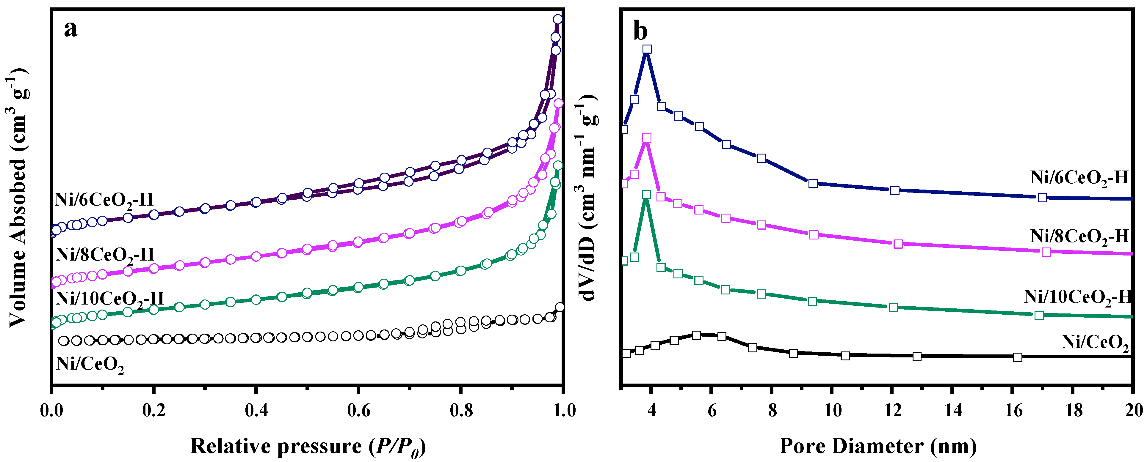
Figure 2 presents the N2 adsorption–desorption isotherms and pore size distribution curves of the as-prepared catalysts. All hollow sphere catalysts exhibited Type IV isotherms, confirming their mesoporous nature. Notably, the hysteresis loops varied among the catalysts: Ni/6CeO2-H displayed a pronounced hysteresis loop over the p/p0 range of 0.4–1.0, while Ni/8CeO2-H and Ni/10CeO2-H showed hysteresis loops in the higher relative pressure range of 0.8–1.0. The broad hysteresis loop observed for Ni/6CeO2-H is characteristic of an H3-type loop, which is typically associated with slit-shaped pores formed by the stacking of plate-like particles [26]. In contrast, the Ni/CeO2 catalyst exhibited a typical Type II isotherm with an H1-type hysteresis loop, indicative of uniform cylindrical mesopores [27]. The pore size distribution curves shown in Figure 2b further confirm that all three hollow sphere catalysts possess well-defined mesoporous structures. The specific surface area, total pore volume, and average pore diameter of each catalyst are summarized in Table 1. Both the specific surface area and total pore volume follow the order Ni/6CeO2-H > Ni/8CeO2-H > Ni/10CeO2-H > Ni/CeO2. Specifically, Ni/6CeO2-H achieves a higher specific surface area of 144.7 m2 g−1, whereas Ni/CeO2 exhibits the lowest value of 81.6 m2 g−1. This trend can be rationalized as follows: as the Ce precursor content increases, the shell thickness of the hollow spheres increases accordingly. Meanwhile, the higher Ce precursor concentration leads to a faster crystal growth rate, resulting in larger nanocrystallite sizes. Since the shell is constructed by the assembly of these nanocrystals, larger building blocks give rise to larger pore diameters. Although the individual pore size increases, the total number of mesopores decreases, leading to a concurrent reduction in both pore volume and specific surface area with increasing Ce precursor content. Consequently, Ni/6CeO2-H, with its superior specific surface area, provides a higher density of accessible active sites, thereby facilitating reactant transport and enhancing the contact between reactant molecules and active sites [26,28].

3.1.2. Redox and Basicity Properties

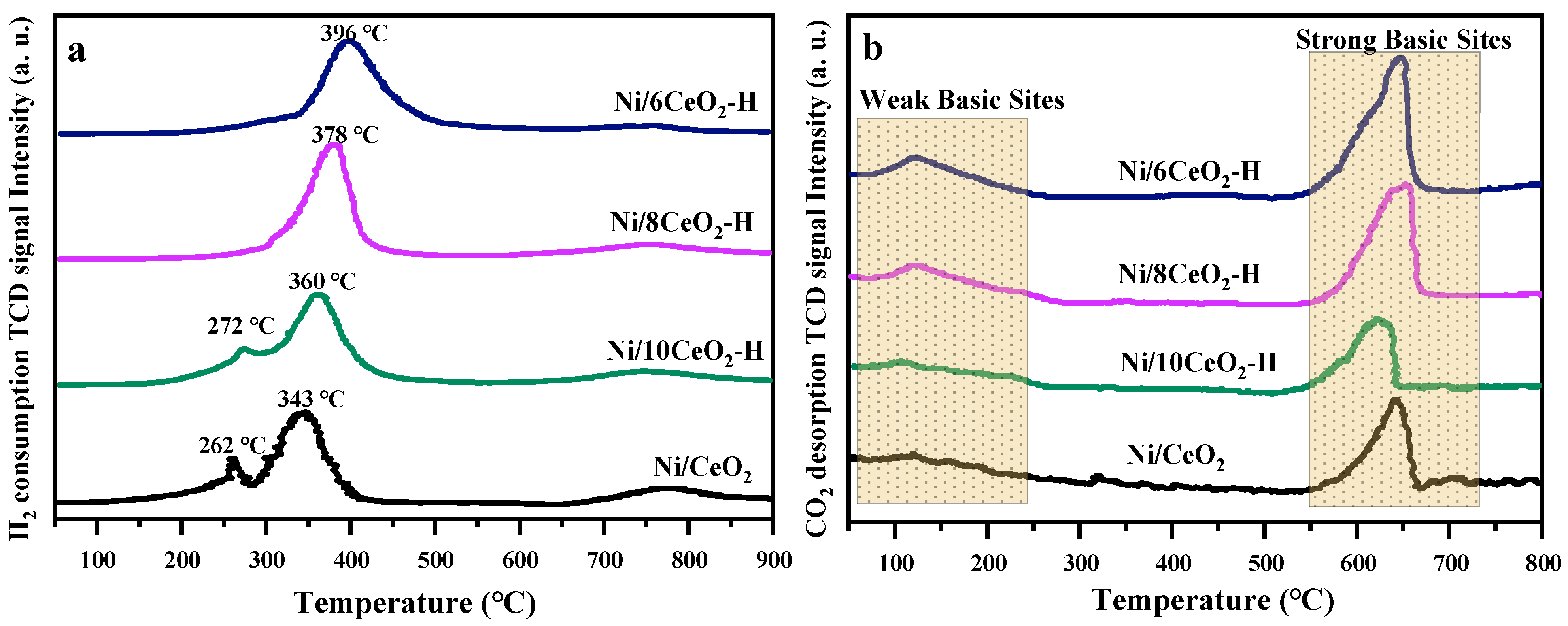
The H2-TPR profiles of the as-prepared catalysts are presented in Figure 3a. It can be observed that Ni/10CeO2-H and Ni/CeO2 exhibit a distinct reduction peak at 272 and 262 °C, respectively, which is attributed to the reduction of NiO particles with weak interaction with the CeO2 support [27]. It is speculated that the low dispersion of Ni species may weaken the Ni–CeO2 interaction, leading to the formation of large-sized NiO particles. Notably, no reduction peak is observed in the H2-TPR profile of Ni/6CeO2-H within the investigated temperature range, which strongly confirms the homogeneous dispersion of NiO within the CeO2 support and the presence of strong internal chemical interactions between them. Furthermore, each catalyst displays a prominent reduction peak at approximately 396, 378, 360, and 343 °C for Ni/6CeO2-H, Ni/8CeO2-H, Ni/10CeO2-H, and Ni/CeO2, respectively, originating from the co-reduction of CeO2 and NiO species [29]. Compared with Ni/8CeO2-H, Ni/10CeO2-H, and Ni/CeO2, the reduction peak of Ni/6CeO2-H shifts to a higher temperature, indicating the presence of strong metal–support interactions. This robust MSI effectively suppresses the agglomeration of Ni particles and promotes their uniform dispersion. Overall, these findings further validate the existence of strong Ni–CeO2 interactions in the hollow sphere-structured catalysts. In addition, all four catalysts show a noticeable reduction peak within the range of 750–800 °C, which originates from the reduction of bulk lattice oxygen in CeO2 [30].
The CO2-TPD profiles of the catalysts shown in Figure 3b typically reveal three distinct desorption regions: the low-temperature zone (ca. 200 °C) corresponds to weak Brønsted basic sites, the medium-temperature zone (ca. 400 °C) is associated with moderate-strength Lewis basic sites, and the high-temperature zone (ca. 600 °C) reflects strong basic sites [21,31]. Experimental results demonstrate that all catalysts exhibit significant CO2 desorption signals in the high-temperature region, confirming the presence of strong basic sites. Notably, the CO2 desorption peak at approximately 120 °C in the low-temperature region becomes increasingly intense as the CeO2 shell thickness decreases, which is attributed to weak Brønsted basic sites formed by surface–OH groups [31]. In contrast, Ni/CeO2 shows no apparent desorption signal in this temperature range. This discrepancy indicates that the hollow sphere structure significantly modulates the distribution of basic sites on CeO2, generating abundant weak basic sites. In the DRM reaction, CH4 preferentially reacts with reactive carbon species formed by adsorbed CO2 on weak basic sites, thereby effectively suppressing coke deposition and enhancing catalytic stability [32,33]. The CO2-TPD results are in good agreement with previous characterization data on coking resistance (e.g., TGA and Raman spectroscopy), providing consistent evidence for the structural advantages of hollow sphere catalysts in mitigating coke formation.

3.2. Physicochemical Characterization of Catalysts After Reaction

3.2.1. Catalytic Evaluation

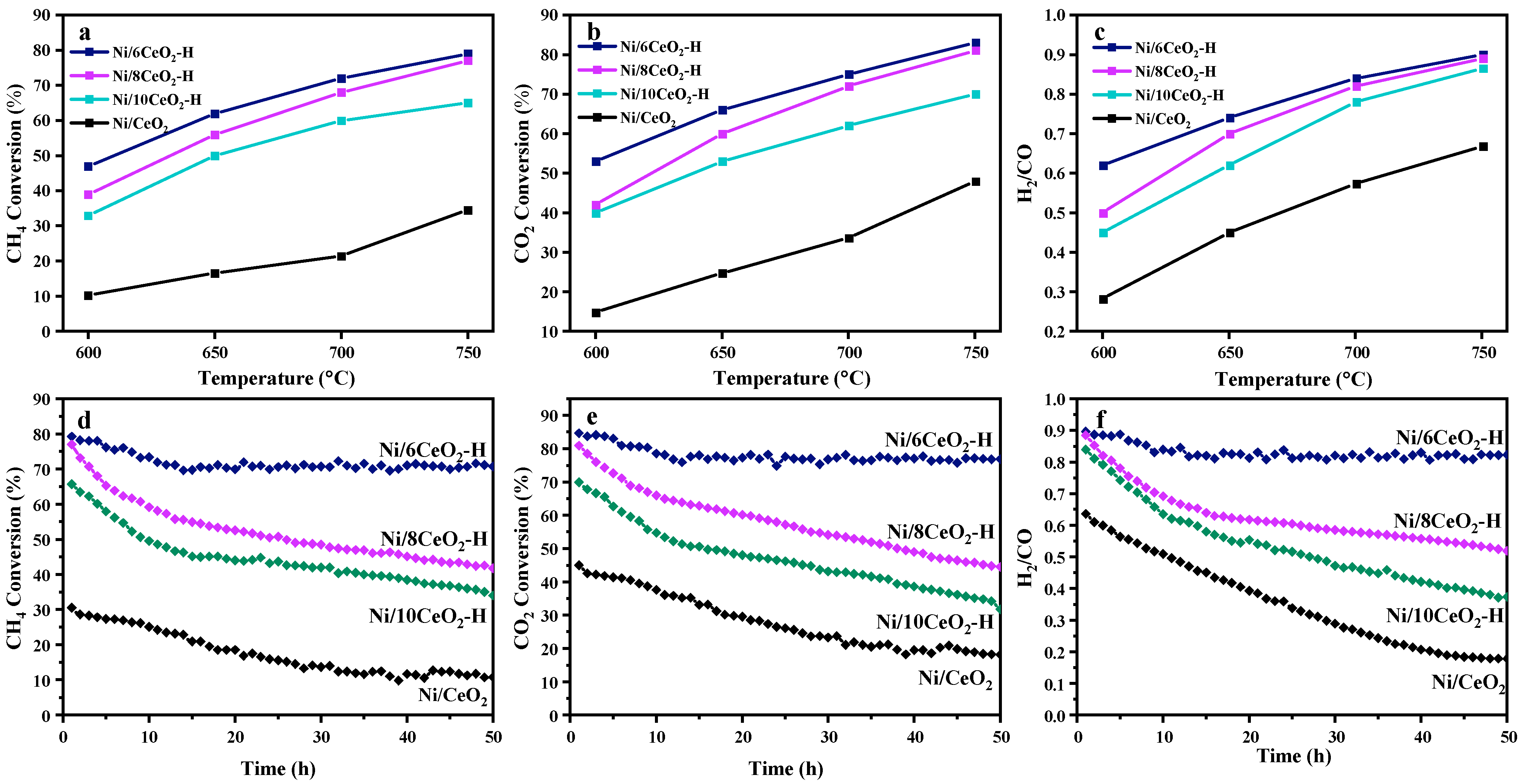
As shown in Figure 4a–c, within the temperature range of 650–750 °C, all catalysts exhibited a consistent activity trend, Ni/6CeO2-H > Ni/8CeO2-H > Ni/10CeO2-H > Ni/CeO2, as reflected by CH4 conversion, CO2 conversion, and the H2/CO molar ratio. These results clearly demonstrate that the hollow spherical structure of the CeO2 support significantly enhances CH4 and CO2 conversion in the DRM reaction. Furthermore, when comparing catalysts supported on hollow CeO2 spheres with different shell thicknesses, thinner shells yielded higher catalytic activity. This can be attributed to the larger specific surface area of thinner CeO2 shells, which promotes higher dispersion of Ni species, exposes more active sites, and shortens reactant diffusion pathways, thereby improving low-temperature activation capability.
As shown in Figure 4d–f, the four catalysts—Ni/6CeO2-H, Ni/8CeO2-H, Ni/10CeO2-H, and Ni/CeO2—displayed markedly distinct catalytic behaviors in terms of CH4 and CO2 conversions and H2/CO molar ratio during the 50 h long-term stability test at 750 °C. Specifically, the CH4 conversion, CO2 conversion, and H2/CO molar ratio over Ni/6CeO2-H gradually approached steady values, indicating reasonable operational stability. Ultimately, the CH4 conversion, CO2 conversion, and H2/CO molar ratio over Ni/6CeO2-H stabilized at 71%, 76%, and 0.81, respectively. In contrast, the CH4 and CO2 conversions and H2/CO molar ratios over Ni/8CeO2-H, Ni/10CeO2-H, and Ni/CeO2 decreased continuously with time without reaching a stable plateau. The persistent decline in both CH4 and CO2 conversions clearly indicates severe catalyst deactivation for these catalysts. Furthermore, as shown in Figure 4f, the H2/CO molar ratio over Ni/CeO2 decreased rapidly with time, which may be attributed to the increasing CO content and decreasing H2 content in the products. This trend is likely associated with the occurrence of the RWGS reaction (CO2 + H2 → CO + H2O) [34]. Concurrently, the Boudouard reaction (C + CO2 → 2CO) may oxidize surface carbon deposits, further contributing to CO formation [35].
Taken together, these results allow a reasonable inference that the four catalysts differ significantly in their ability to activate CO2 and CH4, following the order Ni/6CeO2-H > Ni/8CeO2-H > Ni/10CeO2-H > Ni/CeO2. Moreover, catalyst deactivation is likely closely associated with changes in physicochemical properties, such as agglomeration of surface Ni particles and coverage of active sites by carbon deposits, which will be investigated in detail in the following sections.

3.2.2. Carbon Deposition Analysis of Spent Catalysts

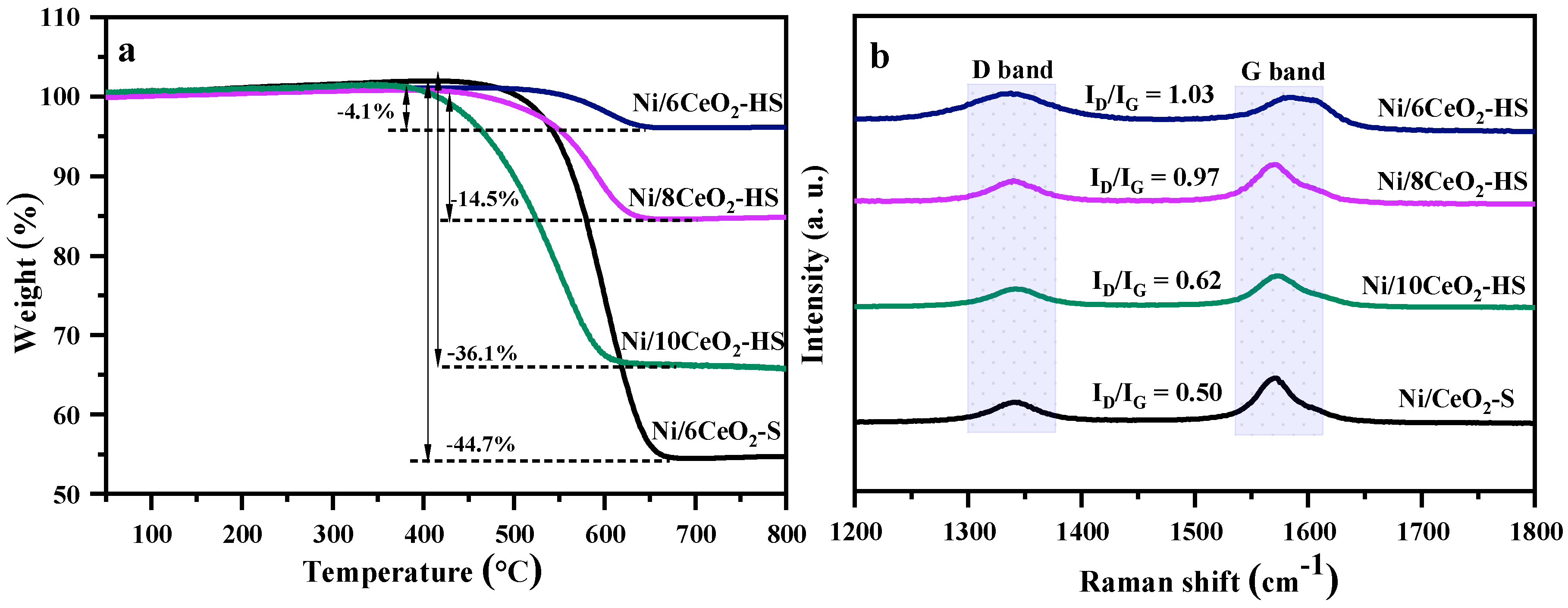
TGA was performed on four spent catalysts after the 50 h long-term stability test, denoted as Ni/6CeO2-HS, Ni/8CeO2-HS, Ni/10CeO2-HS, and Ni/CeO2-S, respectively. The extent of coke deposition was evaluated by continuously monitoring the mass variations during thermal treatment. As shown in Figure 5a, all spent catalysts exhibit distinct mass loss in the temperature range of 400–800 °C, which is primarily attributed to the oxidation of carbonaceous deposits on the catalyst surface. Notably, the weight loss percentages of Ni/6CeO2-HS, Ni/8CeO2-HS, Ni/10CeO2-HS, and Ni/CeO2-S within 400–800 °C are approximately 4.1%, 14.5%, 36.1%, and 44.7%, respectively. Evidently, Ni/6CeO2-HS exhibits the lowest weight loss, strongly indicating its exceptional coke resistance in the DRM reaction. In contrast, Ni/CeO2-S shows the highest weight loss, implying that a substantial amount of coke was deposited on the catalyst surface during the reaction. This result directly accounts for the severe deactivation observed in the long-term stability test.
Raman spectroscopy was further employed to investigate the nature of surface coke species on the spent catalysts. As illustrated in Figure 5b, two characteristic peaks appear at 1340 and 1570 cm−1 for all spent catalysts, which are typically assigned to the D band and G band of carbonaceous deposits, respectively. Generally, the D band originates from defects, structural distortions, and amorphous carbon domains containing C–C (sp3) or C=C (sp2) bonds, whereas the G band is mainly derived from graphitic carbon with the stretching vibration of C=C (sp2) bonds [36]. It has been well established that the graphitization degree of surface coke can be evaluated based on the relative intensity ratio of the D band to the G band (ID/IG) [37]. Herein, the ID/IG values over Ni/6CeO2-HS, Ni/8CeO2-HS, Ni/10CeO2-HS, and Ni/CeO2-S are estimated to be 1.03, 0.97, 0.62, and 0.50, respectively, indicating that the graphitization degree of surface coke increases in the order of Ni/6CeO2-HS < Ni/8CeO2-HS < Ni/10CeO2-HS < Ni/CeO2-S. Clearly, the lowest graphitization degree of coke over Ni/6CeO2-HS further confirms its superior coke resistance in the DRM reaction.

3.2.3. Crystalline Phases

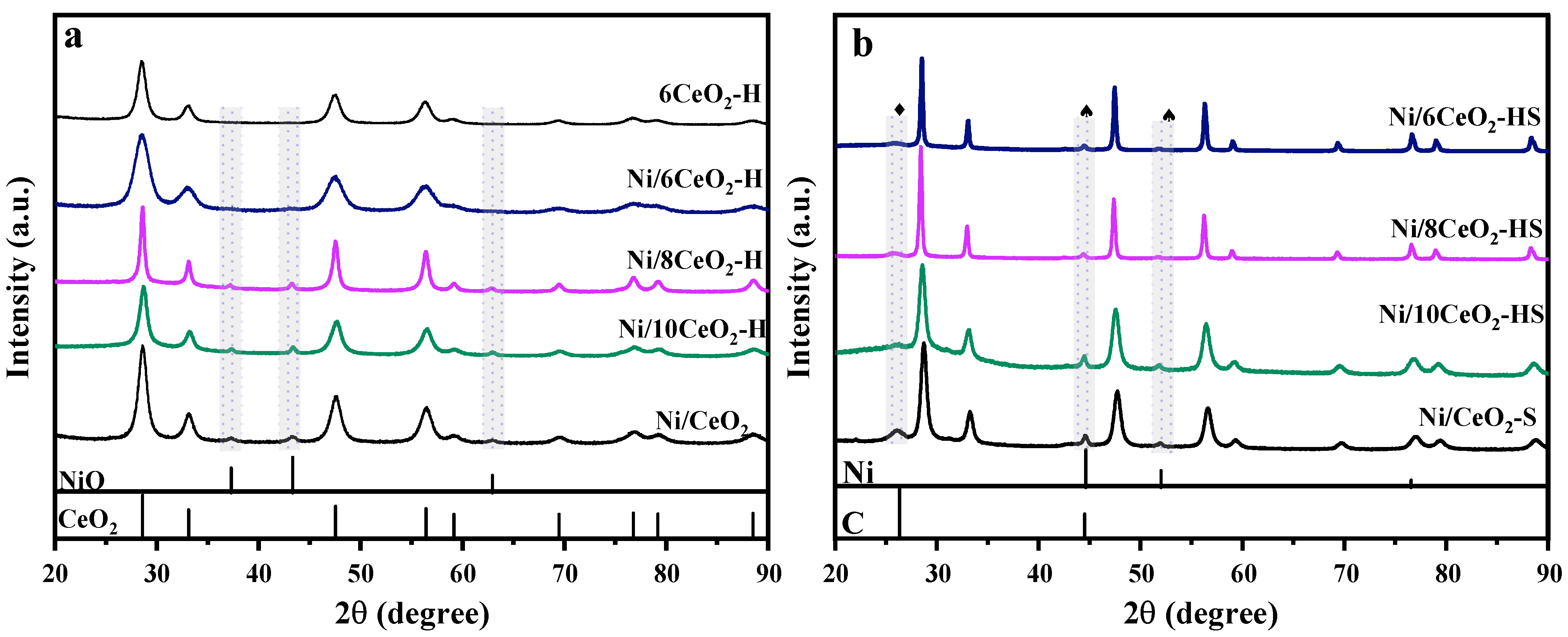
The XRD patterns of the fresh and spent catalysts are presented in Figure 6. As shown in Figure 6a, all fresh catalysts of Ni/6CeO2-H, Ni/8CeO2-H, Ni/10CeO2-H, and Ni/CeO2 exhibit distinct diffraction peaks at 2θ values of 28.5°, 33.0°, 47.5°, 56.3°, 59.0°, 69.4°, 76.7°, 79.0°, and 88.4°, which can be respectively indexed to the (111), (200), (220), (311), (222), (400), (311), (420), and (422) planes of the fluorite-structured CeO2 support (JCPDS PDF#43-1002) [38]. In addition, Ni/8CeO2-H, Ni/10CeO2-H, and Ni/CeO2 display characteristic diffraction peaks at 2θ = 37.2°, 43.3°, and 62.9°, corresponding to the (111), (200), and (220) planes of NiO (JCPDS PDF#47-1049), respectively [38]. Notably, no distinguishable NiO diffraction peaks were detected over the Ni/6CeO2-H catalyst. To eliminate the possibility that the undetectable NiO signals stem from partial incorporation of Ni into the CeO2 lattice, we compared the XRD patterns of Ni/6CeO2-H with those of the pure 6CeO2-H support. No shifts in the CeO2 diffraction peaks were observed for Ni/6CeO2-H, demonstrating that Ni species are highly dispersed as ultrafine nanoparticles on the hollow spherical support, thereby weakening the NiO diffraction signals below the detection limit. In contrast, the NiO particles in the other three catalysts are predominantly present as larger aggregates on the external surface, giving rise to clearly resolvable diffraction peaks.
Figure 6b reveals the XRD patterns of the spent catalysts. Additional diffraction peaks at 2θ = 26.2° and 44.4°, attributable to surface-deposited carbon species (JCPDS PDF#75-1621) [39], are observed for Ni/8CeO2-HS, Ni/10CeO2-HS, and Ni/CeO2-S, with the carbon peak at 26.2° being particularly intense. In contrast, such carbon-related peaks are barely detectable for Ni/6CeO2-HS. These observations indicate that significant coke deposition occurs on the surfaces of Ni/8CeO2-HS, Ni/10CeO2-HS, and Ni/CeO2-S, whereas Ni/6CeO2-HS maintains a markedly lower content of coke deposition. This finding further corroborates the superior coke resistance of Ni/6CeO2-H in the DRM reaction and is in excellent agreement with the TGA and Raman spectroscopy results. Moreover, Figure 6b also displays the characteristic diffraction peaks of metallic Ni on the spent catalysts. Peaks at 2θ = 44.5°, 51.8°, and 76.4° correspond to the (111), (200), and (220) planes of metallic Ni (JCPDS PDF#87-0712), respectively [40]. The peak intensities assignable to metallic Ni over Ni/8CeO2-HS, Ni/10CeO2-HS, and Ni/CeO2-S are substantially higher than those over Ni/6CeO2-HS, indicating that severe metal sintering has occurred on the surface of the thick-shelled hollow spherical and bulk CeO2-supported catalysts during the DRM reaction. In contrast, the strong chemical interaction between Ni and CeO2 in Ni/6CeO2-H effectively anchors the surface Ni particles, suppressing their agglomeration at elevated temperatures and thereby inhibiting metallic Ni sintering.

3.2.4. Morphological Evolution of Spent Catalysts

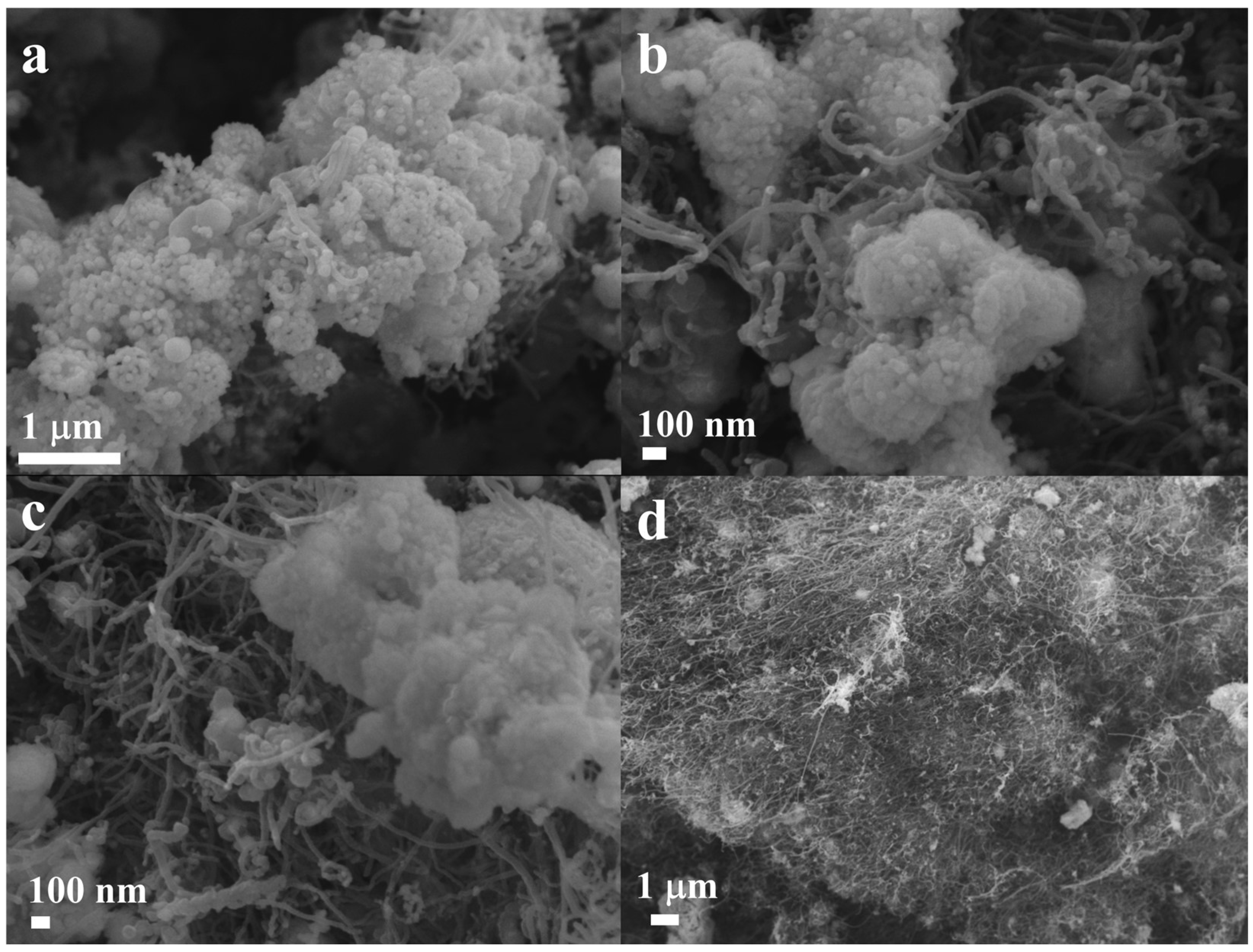
SEM analysis was performed on the catalysts after 50 h of reaction. As shown in Figure 7, the surface of Ni/6CeO2-HS is largely free of coke deposition, whereas extensive carbon accumulation is observed on Ni/8CeO2-HS and Ni/10CeO2-HS. Notably, the surface of Ni/CeO2-S is completely engulfed by coke, which accounts for its rapid deactivation observed in the stability test. In contrast, the absence of coke coverage on Ni/6CeO2-HS allows the Ni particles to preserve their intrinsic activity, thereby endowing this catalyst with superior catalytic stability. These SEM observations are in excellent agreement with the TGA and Raman results, providing direct visual evidence of the distinct coke contents on the spent catalysts. The remarkable coke resistance of Ni/6CeO2-HS can be ascribed to the strong metal–support interaction between Ni and CeO2, which effectively suppresses the agglomeration and growth of carbonaceous species during the reaction.

3.2.5. Surface Valance States of Ni and Ce

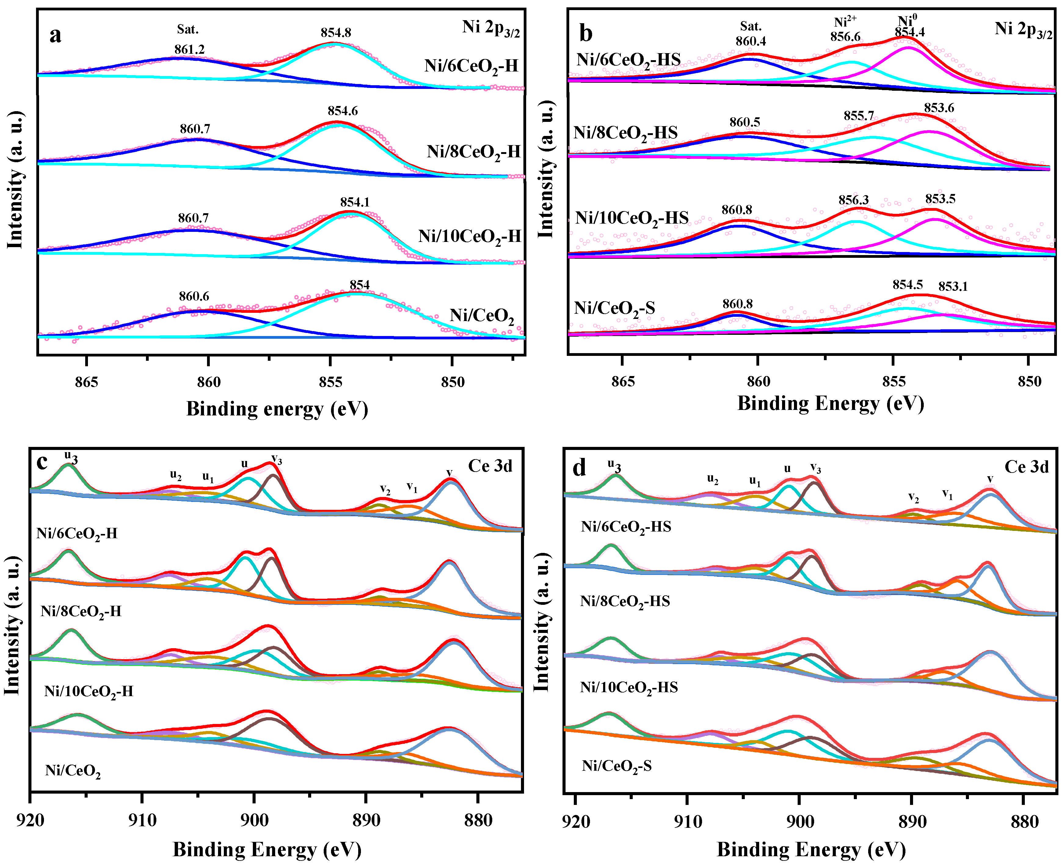
The chemical valence states of Ni and Ce on both fresh and spent catalysts were investigated by XPS. In the Ni 2p3/2 spectra of the fresh catalysts shown in Figure 8a, two characteristic peaks attributed to Ni2+ are observed, with the main peak and satellite peak located at 854.1–854.8 eV and 860.6–861.2 eV, respectively. The binding energies of Ni/6CeO2-H, Ni/8CeO2-H, Ni/10CeO2-H, and Ni/CeO2 are 854.8, 854.6, 854.1, and 854.0 eV, respectively. Notably, catalysts with thinner shells exhibit higher binding energies, indicating stronger metal–support interactions [41]. In the Ni 2p3/2 spectra of the spent catalysts presented in Figure 7b, an additional peak corresponding to metallic Ni0 emerges in the range of 853.1–854.4 eV. Since metallic Ni is widely recognized as the active center for CH4 adsorption and activation, the proportion of Ni0 species is closely correlated with the initial CH4 conversion. According to Silva et al. [42,43], increasing the electron density at Ni0 active sites enables electron transfer from Ni0 to the antibonding orbitals of the C–H bonds in CH4, thereby effectively promoting methane dissociation and inducing C–H bond cleavage. To further verify the relationship between reducibility and shell thickness, the ratio of Ni0/(Ni0 + Ni2+) was calculated [44]. As summarized in Table 2, the Ni0/(Ni0 + Ni2+) ratios for Ni/6CeO2-HS, Ni/8CeO2-HS, Ni/10CeO2-HS, and Ni/CeO2 are 0.63, 0.60, 0.48, and 0.40, respectively. The higher Ni0 density on Ni/6CeO2-HS indicates a greater number of accessible active sites, which accounts for its enhanced catalytic activity.
In the Ce 3d XPS spectra of all catalysts shown in Figure 8c,d, several characteristic multiplet splitting patterns are observed, which can be attributed to Ce3+ (u1, v1) and Ce4+ (u, u2, u3, v, v2, v3) species [45,46]. The proportion of Ce3+ relative to the total Ce3+ and Ce4+ can be estimated by calculating the ratio of the peak area assignable to Ce3+ to the total peak area of the Ce 3d spectra, at listed in Table 2. The fresh catalysts exhibit Ce3+/(Ce3+ + Ce4+) ratios in the order of Ni/6CeO2-H > Ni/8CeO2-H > Ni/10CeO2-H > Ni/CeO2, indicating a higher surface concentration of Ce3+ species on Ni/6CeO2-H. Additionally, the spent catalysts display distinct redox behaviors under reaction conditions. After the DRM reaction, the Ce3+/(Ce3+ + Ce4+) ratio of Ni/6CeO2-HS decreases from 0.35 to 0.21, representing the most pronounced reduction among all catalysts. The ratios for Ni/8CeO2-H, Ni/10CeO2-H, and Ni/CeO2 decrease from 0.23 to 0.17, from 0.18 to 0.14, and from 0.17 to 0.15, respectively. These variations demonstrate that the Ce species in Ni/6CeO2-H participate more extensively in the redox cycles under reaction conditions [47].
Notably, two quantitative XPS results clearly verify this enhanced synergism. First, fresh Ni/6CeO2-H delivers the highest Ni 2p3/2 binding energy of 854.8 eV, revealing the strongest electron transfer from Ni cations to the ceria support. Second, it also owns the maximum Ce3+/(Ce3+ + Ce4+) ratio of 0.35, corresponding to abundant surface oxygen vacancies originating from Ni–Ce electronic exchange. After DRM reaction, Ni/6CeO2-H exhibits the most dramatic decrease in Ce3+ proportion and the largest Ni0/(Ni0 + Ni2+) value of 0.63, which confirms extensive Ce-involved redox cycles and abundant stabilized metallic Ni sites under working conditions. Combined analysis of the Ni 2p3/2 and Ce 3d XPS data reveals that Ni/6CeO2-H exhibits superior Ni–Ce synergistic effects compared to the other three catalysts.

3.3. Surface Reaction Process by TPSR

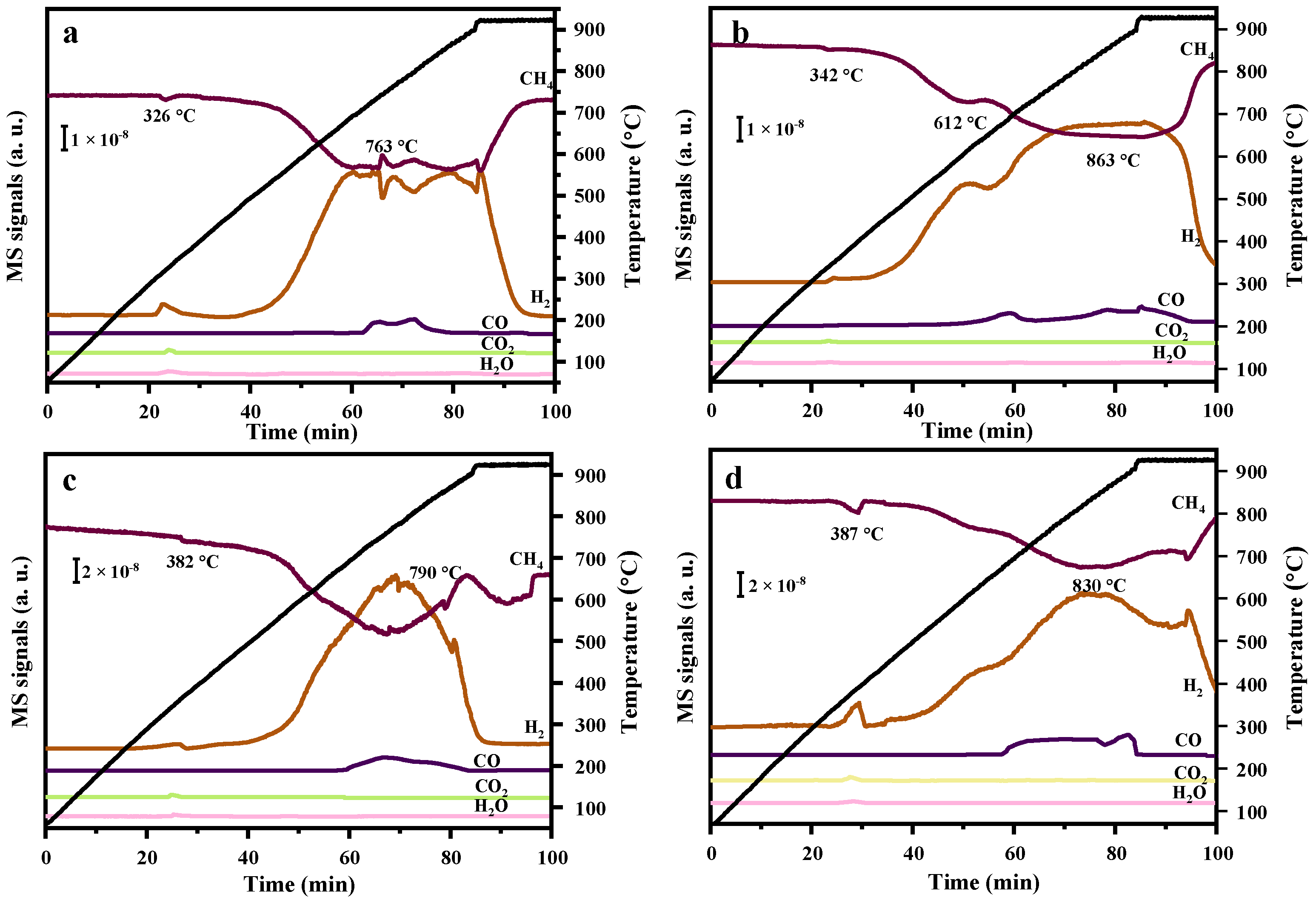
The CH4-TPSR (temperature-programmed surface reaction) profiles of Ni/6CeO2-H, Ni/8CeO2-H, Ni/10CeO2-H, and Ni/CeO2 catalysts are presented in Figure 9a–d. Real-time monitoring of CH4 consumption and product signals (H2, CO, CO2, H2O) by mass spectrometry reveals the influence of CeO2 hollow sphere shell thickness on CH4 activation, dissociation, and carbon gasification over the catalyst surfaces. Distinct CH4 consumption peaks are observed at 326, 342, 382, and 387 °C for Ni/6CeO2-H, Ni/8CeO2-H, Ni/10CeO2-H, and Ni/CeO2, respectively, accompanied by simultaneous H2 generation and synchronous CO2 and H2O signal peaks [48,49]. These products originate from the oxidation of unstable CHx* species, generated by CH4 dissociation, by adsorbed oxygen species on the catalyst surface. The onset temperature of CH4 consumption directly reflects the catalytic activation capability. The fact that Ni/6CeO2-H achieves rapid partial CH4 activation at as low as 326 °C indicates that its thin-shell structure endows the catalyst with a higher specific surface area, abundant CeO2 oxygen vacancies, and highly dispersed Ni active sites, establishing strong metal–support interactions that significantly lower the energy barrier for C–H bond cleavage [50].
In addition to the low-temperature activation differences, all catalysts exhibit intense H2 signals in the high-temperature region at 763, 863, 790, and 830 °C, respectively. Notably, Ni/6CeO2-H initiates strong CH4 cracking at a relatively low temperature of 763 °C, which is fully consistent with its superior low-temperature performance. This further confirms that the thin-shell design exposes more Ni active sites and CeO2 oxygen vacancies owing to the higher specific surface area, thereby promoting deep CH4 dissociation. The H2 peak of Ni/8CeO2-H appears at a higher temperature of 863 °C, while that of Ni/10CeO2-H emerges at 790 °C but exhibits a stronger overall high-temperature cracking capability. The intensities of both CH4 consumption and H2 generation follow the order Ni/6CeO2-H < Ni/8CeO2-H < Ni/10CeO2-H < Ni/CeO2 (with signal scales of 1 × 10⁻⁸ for panels a and b, and 2 × 10⁻⁸ for panels c and d), indicating that Ni/10CeO2-H and Ni/CeO2 possess the strongest CH4 cracking ability. This can be attributed to the larger Ni particles supported on these catalysts. It has been demonstrated that larger Ni nanoparticles exhibit stronger C–H bond cleavage capability toward CH4 at elevated temperatures, generating a greater quantity of CHx* species [12]. These CHx* species undergo further cracking to produce substantial carbon deposits. Accordingly, during the DRM stability tests, the catalytic activity profiles of Ni/10CeO2-H and Ni/CeO2 fail to reach a stable plateau and instead decline continuously, indicating that the generated coke cannot be effectively removed. This leads to progressive coverage of surface Ni particles by carbon deposits, ultimately resulting in catalyst deactivation.
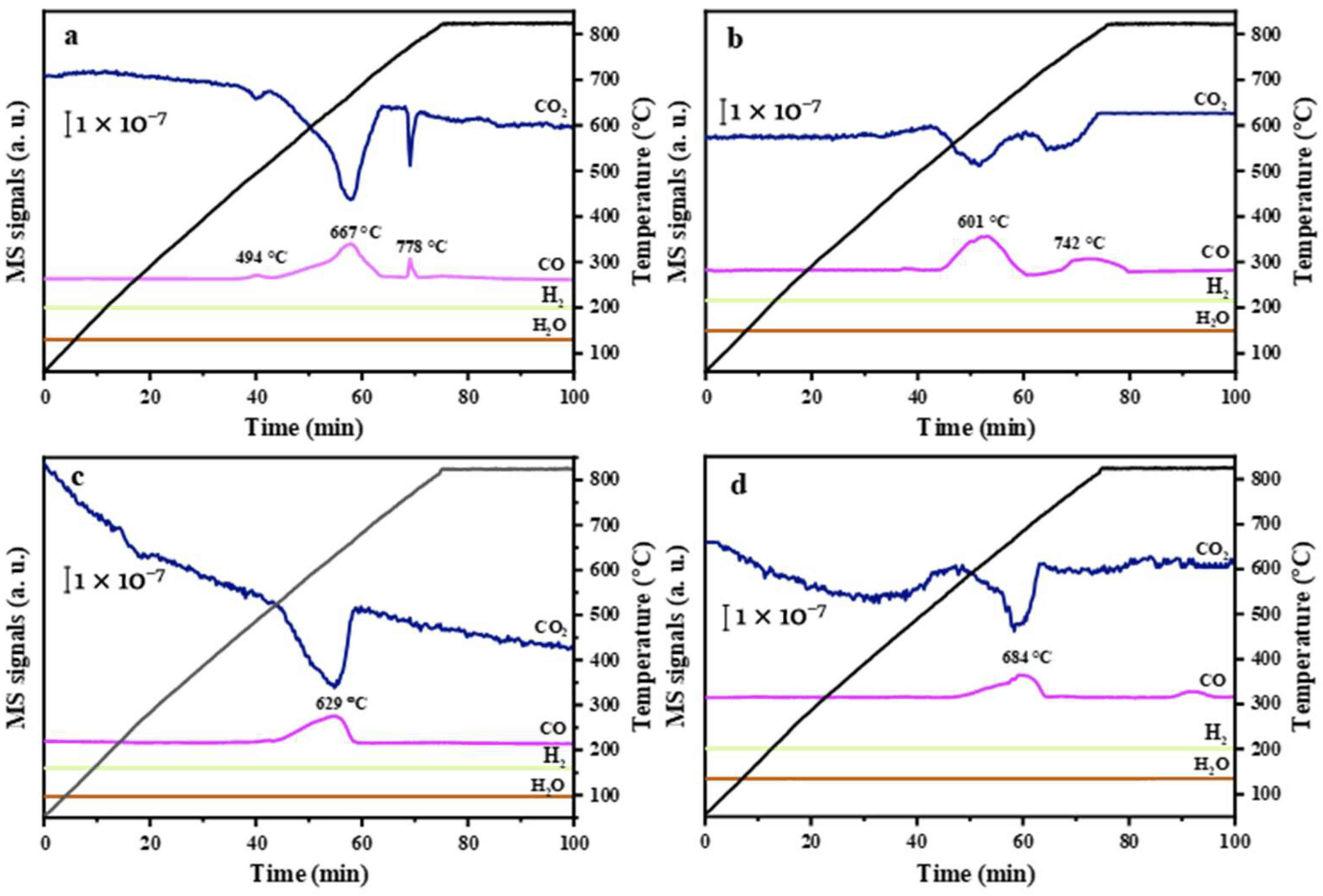
To evaluate the coke removal capability by CO2, CO2-TPSR analysis was subsequently performed over the catalysts following CH4-TPSR tests. Figure 10a–d present the CO2-TPSR profiles of Ni/6CeO2-H, Ni/8CeO2-H, Ni/10CeO2-H, and Ni/CeO2, respectively. Temperature-programmed heating under pure CO2 atmosphere with real-time mass spectrometric monitoring of CO2 consumption and product signals (CO, H2, H2O) reveals the regulatory effect of CeO2 hollow sphere shell thickness on CO2 activation capability, dissociation efficiency, and oxygen species supply. The CO2 consumption in CO2-TPSR originates from CO2 dissociation and the reaction of CO2 with carbonaceous species to produce CO. As the shell thickness increases from thin to thick, the CO2 activation performance of the catalysts decreases significantly. Ni/6CeO2-H exhibits a distinct CO2 signal drop at as low as 429 °C, whereas Ni/8CeO2-H, Ni/10CeO2-H, and Ni/CeO2 show no detectable CO2 consumption within this temperature range. This indicates that the thin-shell structure enables effective CO2 adsorption and dissociation into CO and reactive O* species at low temperatures, while the thick-shell structure substantially restricts CO2 adsorption capacity [51]. Under identical MS signal scales (1 × 10⁻⁷), Ni/10CeO2-H and Ni/CeO2 display only a single, weak CO peak at approximately 629 and 684 °C, respectively, with peak intensities far lower than those of the former two catalysts. This demonstrates that the thick-shell structure severely hinders Ni exposure and oxygen vacancy utilization, resulting in the lowest CO2-to-CO conversion efficiency. Furthermore, the absence of pronounced CO2 consumption peaks suggests that substantial coke deposition occurred during the preceding CH4-TPSR test, which further compromises the CO2 activation capability of Ni/10CeO2-H and Ni/CeO2 [50].

3.4. Reaction Mechanism by In Situ DRIFT Spectra

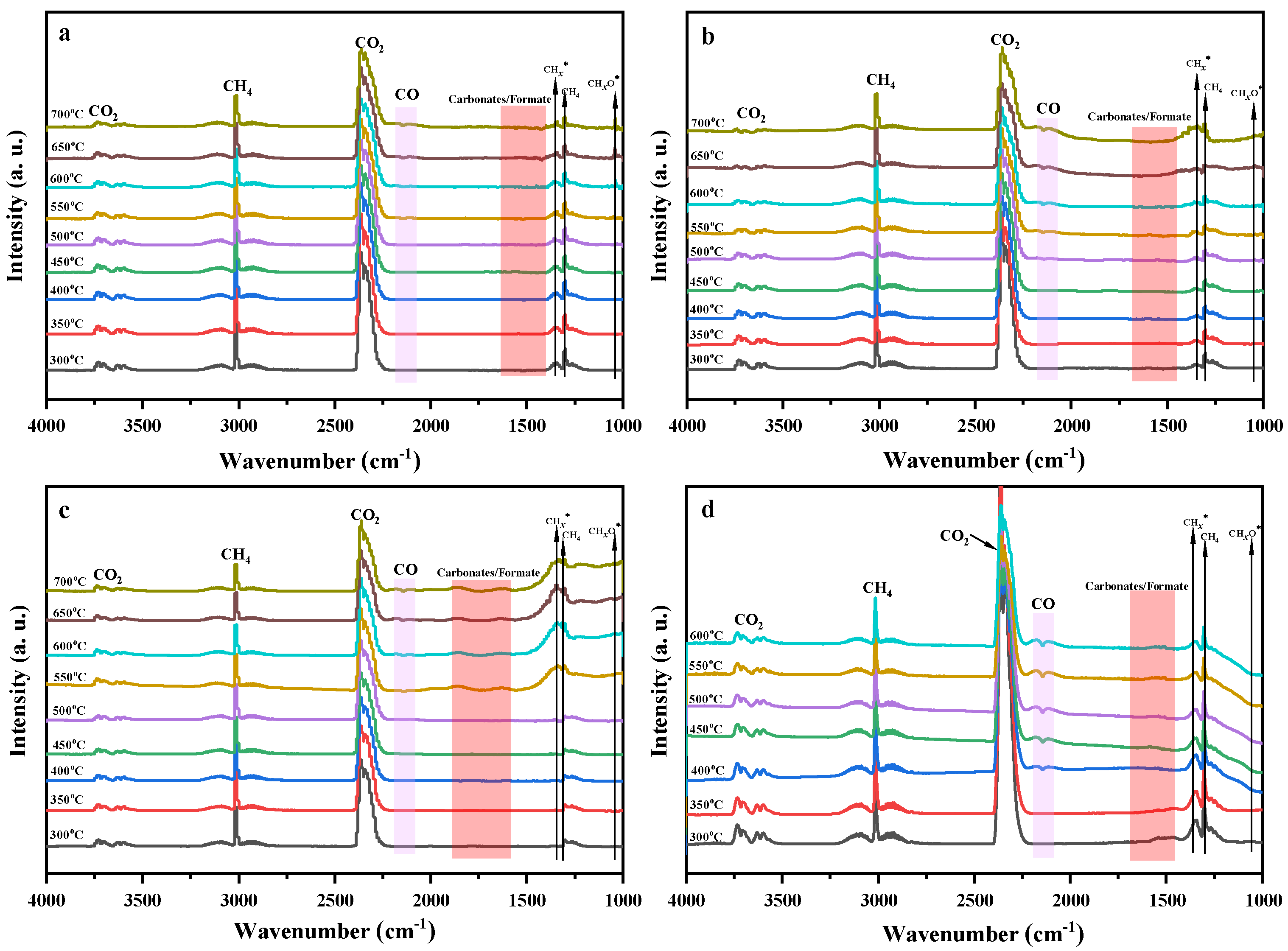
Figure 11 presents the in situ DRIFT spectra of the as-prepared catalysts under temperature-programmed operation in a CH4/CO2/Ar feed mixture. The representative DRM reaction pathways along with the intermediates identified in the DRIFT spectra are outlined in Equations (4)–(11). It is noteworthy that Figure 11d cannot provide reliable temperature-dependent IR spectra for subsequent analysis due to severe coke deposition on Ni/CeO2 above 600 °C. Various intermediates involved in the DRM reaction are clearly detected in the DRIFT spectra. Specifically, the IR signals assignable to gas-phase CH4 (3016/1304 cm−1) and gas-phase CO2 (3752/3600 and 2240–2400 cm−1) gradually weaken with increasing reaction temperature, which is well consistent with the thermodynamic characteristics of the DRM reaction [52,53]. The IR peak at 1540 cm−1 corresponds to bicarbonate (HCO3*) species formed via the reaction of CO2 with –OH (Equation (4)) [54]. The IR peaks in the range of 1520–1400 cm−1 indicate the presence of carbonate (CO3*) species, likely derived from the reaction of CO2 with O* (Equation (5)) [50]. The IR signal at 2120–2180 cm−1 serves as a characteristic indicator of gas-phase CO, while the peak at 1346 cm−1 is assigned to the asymmetric vibration of CHx* species, revealing the formation pathway of CHx* and H* from CH4 cracking (Equation (6)) [55]. The appearance of HCOO* species, with an IR band at 1600 cm−1, may arise from the reactions between HCO3*/CO3* and H* (Equations (7) and (8)) [54]. In addition, the reaction of CHx* with –OH yields CHxO* species (Equation (9)), giving rise to an IR peak at 1050 cm−1. Both HCOO* and CHxO* are critical unstable intermediates in the DRM reaction, as they rapidly decompose into CO and –OH (Equation (10)) or CO and H* (Equation (11)).
Further observations of Figure 11a reveal that the IR signals of CH4 and CO2 over the Ni/6CeO2-H catalyst undergo significant changes in the temperature range of 300–700 °C. The progressive decrease in the IR signals of CH4 and CO2 with increasing temperature indicates the high catalytic activity of this catalyst toward CH4 and CO2 conversion. The IR peak intensities of CHx* species over Ni/6CeO2-H gradually decrease with rising temperature, whereas the IR peak intensity of CHxO* exhibits an opposite trend, thereby confirming that CHxO* species is formed via the reaction of CHx* with –OH. Since CHx* derived from CH4 cracking is regarded as a key precursor for coke deposition, its further cracking leads to surface coke accumulation and subsequent catalyst deactivation. The timely conversion of CHx* to CHxO* over Ni/6CeO2-H can effectively reduce the probability of coke formation, thereby enhancing its coke resistance during the reaction. In contrast, as shown in Figure 11b–d, no distinct IR peak attributable to CHxO* species is observed over Ni/8CeO2-H, Ni/10CeO2-H, and Ni/CeO2, while the IR signals of CHx* species become increasingly intense. The CHx* species generated during the reaction cannot be effectively consumed, resulting in continuous cracking of CHx* into substantial coke deposits and ultimately severe catalyst deactivation.
Based on the in situ DRIFTS results, a plausible reaction mechanism for DRM over the reduced Ni/6CeO2-H catalyst can be proposed, as illustrated in Scheme 1. The CO2 conversion pathway primarily relies on the CeO2 support, involving O* to form CO3* species and –OH-mediated activation to form HCO3* species. The resulting CO3* and HCO3* intermediates further react with H* to generate unstable HCOO* species, which rapidly decompose into CO and –OH. Meanwhile, CH4 activation is predominantly catalyzed by metallic Ni particles, dissociating into CHx* fragments and H*. According to the CO2-TPD results (Figure 3b), the Ni/CeO2 catalyst exhibits insufficient CO2 activation capacity, which significantly suppresses the HCOO* formation pathway. The inadequate supply of –OH species hinders the reaction between CHx* and –OH to form CHxO* intermediates, thereby promoting further fragmentation of CHx* and the formation of surface carbon deposits. Moreover, the thick-shelled hollow structure and the relatively large Ni particles on the Ni/CeO2 surface facilitate graphitization of carbon precursors, exacerbating coke formation, as corroborated by the Raman spectra in Figure 5b [56].
C O + O H H C O 3
C O 2 + O C O 3
C H 4 C H x + H
H C O 3 + H H C O O + O H
C O 3 + H H C O O + O
C H x + O H C H x O + H
H C O O O H + C O
C H x O C O + H
In contrast, the thin-shelled architecture of Ni/6CeO2-H substantially enhances CO2 activation, thereby generating reactive surface –OH species that readily react with CHx* fragments. In this process, the –OH species serve as “coke precursor scavengers,” not only promoting the conversion of CHx* to CHxO but also effectively suppressing coke deposition on Ni/6CeO2-H. The strong Ni–Ce interfacial interaction over the reduced Ni/6CeO2-H catalyst further facilitates the participation of –OH species in the reaction, accelerating the removal of carbon precursors and inhibiting coke formation.

4. Conclusions

CeO2 hollow sphere supports were successfully synthesized via a hard template method combined with a hydrothermal approach, with the shell thickness precisely controlled by tuning the precursor feeding ratio. DRM evaluation revealed that the Ni/6CeO2-H catalyst exhibited significantly superior catalytic activity and stability compared to Ni/8CeO2-H, Ni/10CeO2-H, and Ni/CeO2. This outstanding performance was primarily attributed to the thin-shell architecture, which endowed the catalyst with a higher specific surface area and pore volume, thereby exposing more Ni active sites. Moreover, the Ni/6CeO2-H catalyst possessed excellent CO2 activation capability and abundant weak basic sites, facilitating the in situ generation of a large quantity of surface –OH species that effectively gasified and eliminated coke deposits, thus preserving long-term catalytic activity and stability. In situ diffuse reflectance infrared Fourier transform spectroscopy further demonstrated that surface –OH groups served as the critical active species in the DRM reaction. These –OH groups not only participated in CO2 activation and its subsequent conversion into carbonate/formate intermediates but also effectively suppressed the further decomposition of CHx* species derived from CH4 cracking, thereby preventing coke deposition.

Supplementary Materials

The following supporting information can be downloaded at https://www.mdpi.com/article/10.3390/nano16140868/s1.

Author Contributions

Conceptualization, J.L. and C.Z.; methodology, J.L.; software, J.L.; validation, J.L. and T.C.; formal analysis, J.L. and H.C.; investigation, J.L.; resources, C.Z.; data curation, J.L.; writing—original draft preparation, J.L.; writing—review and editing, C.Z.; visualization, J.L.; supervision, C.Z.; project administration, C.Z.; funding acquisition, C.Z. All authors have read and agreed to the published version of the manuscript.

Funding

This research received no external funding.

Data Availability Statement

The original contributions presented in this study are included in the article/Supplementary Materials. Further inquiries can be directed to the corresponding author.

Acknowledgments

This work receives financial research funding from the Natural Science Foundation of Shandong province (ZR2025MS164) and the National Natural Science Foundation of China (No. 22076088).

Conflicts of Interest

The authors declare no conflicts of interest.

References

  1. Cael, B.B.; Goodwin, P.A. Global methane pledge versus carbon dioxide emission reduction. Environ. Res. Lett. 2023, 18, 104015. [Google Scholar] [CrossRef]
  2. Liu, J.; Zhang, J.; Hua, Y.; Gao, Z. CeO2 Nanorod-Supported Ni–Co Catalysts for Stable and Efficient Dry Reforming of Methane. ChemNanoMat 2026, 12, e202500649. [Google Scholar] [CrossRef]
  3. Song, C.; Liu, Q.; Ji, N.; Deng, S.; Zhao, J.; Li, Y.; Song, Y.; Li, H. Alternative pathways for efficient CO2 capture by hybrid processes—A review. Renew. Sust. Energ. Rev. 2018, 82, 215–231. [Google Scholar] [CrossRef]
  4. Lin, T.-Y.; Chiu, Y.-H.; Lin, Y.-N.; Chang, T.-H.; Lin, P.-Y. Greenhouse gas emission indicators, energy consumption efficiency, and optimal carbon emission allowance allocation of the EU countries in 2030. Gas Sci. Eng. 2023, 110, 204902. [Google Scholar] [CrossRef]
  5. Jang, W.-J.; Shim, J.-O.; Kim, H.-M.; Yoo, S.-Y.; Roh, H.-S. A review on dry reforming of methane in aspect of catalytic properties. Catal. Today 2019, 324, 15–26. [Google Scholar] [CrossRef]
  6. Wittich, K.; Krämer, M.; Bottke, N.; Schunk, S.A. Catalytic Dry Reforming of Methane: Insights from Model Systems. ChemCatChem 2020, 12, 2130–2147. [Google Scholar] [CrossRef]
  7. Abdulrasheed, A.; Jalil, A.A.; Gambo, Y.; Ibrahim, M.; Hambali, H.U.; Shahul Hamid, M.Y. A review on catalyst development for dry reforming of methane to syngas: Recent advances. Renew. Sust. Energ. Rev. 2019, 108, 175–193. [Google Scholar] [CrossRef]
  8. Li, S.; Fu, Y.; Kong, W.; Pan, B.; Yuan, C.; Cai, F.; Zhu, H.; Zhang, J.; Sun, Y. Dually confined Ni nanoparticles by room-temperature degradation of AlN for dry reforming of methane. Appl. Catal. B-Environ. 2020, 277, 118921. [Google Scholar] [CrossRef]
  9. Jagadeesh, P.; Varun, Y.; Himajaa Reddy, B.; Sreedhar, I.; Singh, S.A. A short review on recent advancements of dry reforming of methane (DRM) over pyrochlores. Mater. Today Proc. 2023, 72, 361–369. [Google Scholar] [CrossRef]
  10. Ekeoma, B.C.; Yusuf, M.; Johari, K.; Abdullah, B. Mesoporous silica supported Ni-based catalysts for methane dry reforming: A review of recent studies. Int. J. Hydrogen Energy 2022, 47, 41596–41620. [Google Scholar] [CrossRef]
  11. Safavinia, B.; Wang, Y.; Jiang, C.; Roman, C.; Darapaneni, P.; Larriviere, J.; Cullen, D.A.; Dooley, K.M.; Dorman, J.A. Enhancing CexZr1–xO2 Activity for Methane Dry Reforming Using Subsurface Ni Dopants. ACS Catal. 2020, 10, 4070–4079. [Google Scholar] [CrossRef]
  12. Damaskinos, C.M.; Zavašnik, J.; Djinović, P.; Efstathiou, A.M. Dry reforming of methane over Ni/Ce0.8Ti0.2O2-δ: The effect of Ni particle size on the carbon pathways studied by transient and isotopic techniques. Appl. Catal. B-Environ. 2021, 296, 120321. [Google Scholar] [CrossRef]
  13. Rood, S.C.; Ahmet, H.B.; Gomez-Ramon, A.; Torrente-Murciano, L.; Reina, T.R.; Eslava, S. Enhanced ceria nanoflakes using graphene oxide as a sacrificial template for CO oxidation and dry reforming of methane. Appl. Catal. B-Environ. 2019, 242, 358–368. [Google Scholar] [CrossRef]
  14. Peng, H.; Zhang, X.; Han, X.; You, X.; Lin, S.; Chen, H.; Liu, W.; Wang, X.; Zhang, N.; Wang, Z.; et al. Catalysts in Coronas: A Surface Spatial Confinement Strategy for High-Performance Catalysts in Methane Dry Reforming. ACS Catal. 2019, 9, 9072–9080. [Google Scholar] [CrossRef]
  15. Tang, Y.; Wei, Y.; Wang, Z.; Zhang, S.; Li, Y.; Nguyen, L.; Li, Y.; Zhou, Y.; Shen, W.; Tao, F.F.; et al. Synergy of Single-Atom Ni1 and Ru1 Sites on CeO2 for Dry Reforming of CH4. J. Am. Chem. Soc. 2019, 141, 7283–7293. [Google Scholar] [CrossRef] [PubMed]
  16. Polo-Garzon, F.; Pakhare, D.; Spivey, J.J.; Bruce, D.A. Dry Reforming of Methane on Rh-Doped Pyrochlore Catalysts: A Steady-State Isotopic Transient Kinetic Study. ACS Catal. 2016, 6, 3826–3833. [Google Scholar] [CrossRef]
  17. Zhou, R.; Mohamedali, M.; Ren, Y.; Lu, Q.; Mahinpey, N. Facile synthesis of multi-layered nanostructured Ni/CeO2 catalyst plus in-situ pre-treatment for efficient dry reforming of methane. Appl. Catal. B-Environ. 2022, 316, 121696. [Google Scholar] [CrossRef]
  18. Maciel, C.G.; Silva, T.d.F.; Hirooka, M.I.; Belgacem, M.N.; Assaf, J.M. Effect of nature of ceria support in CuO/CeO2 catalyst for PROX-CO reaction. Fuel 2012, 97, 245–252. [Google Scholar] [CrossRef]
  19. Luisetto, I.; Tuti, S.; Romano, C.; Boaro, M.; Di Bartolomeo, E.; Kesavan, J.K.; Kumar, S.S.; Selvakumar, K. Dry reforming of methane over Ni supported on doped CeO2: New insight on the role of dopants for CO2 activation. J. CO2. Util. 2019, 30, 63–78. [Google Scholar] [CrossRef]
  20. Marinho, A.L.A.; Rabelo-Neto, R.C.; Epron, F.; Bion, N.; Toniolo, F.S.; Noronha, F.B. Embedded Ni nanoparticles in CeZrO2 as stable catalyst for dry reforming of methane. Appl. Catal. B-Environ. 2020, 268, 118387. [Google Scholar] [CrossRef]
  21. Xie, Z.; Yan, B.; Kattel, S.; Lee, J.H.; Yao, S.; Wu, Q.; Rui, N.; Gomez, E.; Liu, Z.; Xu, W.; et al. Dry reforming of methane over CeO2-supported Pt-Co catalysts with enhanced activity. Appl. Catal. B-Environ. 2018, 236, 280–293. [Google Scholar] [CrossRef]
  22. Vasiliades, M.A.; Damaskinos, C.M.; Lykaki, M.; Stefa, S.; Binas, V.D.; Kentri, T.; Boghosian, S.; Konsolakis, M.; Efstathiou, A.M. Deciphering the role of nano-CeO2 morphology on the dry reforming of methane over Ni/CeO2 using transient and isotopic techniques. Appl. Catal. B Environ. Energy 2024, 350, 123906. [Google Scholar] [CrossRef]
  23. Daza, C.E.; Gallego, J.; Mondragón, F.; Moreno, S.; Molina, R. High stability of Ce-promoted Ni/Mg–Al catalysts derived from hydrotalcites in dry reforming of methane. Fuel 2010, 89, 592–603. [Google Scholar] [CrossRef]
  24. Xie, S.; He, J.; Gao, Y.; Su, J.; Wu, C.-E.; Zhang, W.; Wu, M.; Xu, L.; Cui, Y.; Chen, M. Structure-property engineering of mesoporous CeO2 hollow nanospheres for efficient catalytic oxidation of toluene. Fuel 2026, 426, 123529. [Google Scholar] [CrossRef]
  25. Zhang, B.; Huang, S.; Li, Y.; Shen, J.; Tian, X.; Ding, M. Highly dispersed Cu on hollow spherical CeO2: An efficient and stable catalyst for the RWGS reaction. Appl. Catal. B-Environ. 2025, 366, 125003. [Google Scholar] [CrossRef]
  26. Zhang, J.; Gong, M.; Tian, C.; Wang, C.-A. Facile synthesis of well-defined CeO2 hollow spheres with a tunable pore structure. Ceram. Int. 2016, 42, 6088–6093. [Google Scholar] [CrossRef]
  27. Sellers-Antón, B.; Bailón-García, E.; Cardenas-Arenas, A.; Davó-Quiñonero, A.; Lozano-Castelló, D.; Bueno-López, A. Enhancement of the Generation and Transfer of Active Oxygen in Ni/CeO2 Catalysts for Soot Combustion by Controlling the Ni–Ceria Contact and the Three-Dimensional Structure. Environ. Sci. Technol. 2020, 54, 2439–2447. [Google Scholar] [CrossRef] [PubMed]
  28. Zhang, Q.; Feng, X.; Liu, J.; Zhao, L.; Song, X.; Zhang, P.; Gao, L. Hollow hierarchical Ni/MgO-SiO2 catalyst with high activity, thermal stability and coking resistance for catalytic dry reforming of methane. Int. J. Hydrogen Energy 2018, 43, 11056–11068. [Google Scholar] [CrossRef]
  29. Le, T.A.; Kim, M.S.; Lee, S.H.; Kim, T.W.; Park, E.D. CO and CO2 methanation over supported Ni catalysts. Catal. Today 2017, 293–294, 89–96. [Google Scholar] [CrossRef]
  30. Wang, J.; Cheng, L.; An, W.; Xu, J.; Men, Y. Boosting soot combustion efficiencies over CuO–CeO2 catalysts with a 3DOM structure. Catal. Sci. Technol. 2016, 6, 7342–7350. [Google Scholar] [CrossRef]
  31. Aziz, M.A.A.; Jalil, A.A.; Wongsakulphasatch, S.; Vo, D.-V.N. Understanding the role of surface basic sites of catalysts in CO2 activation in dry reforming of methane: A short review. Catal. Sci. Technol. 2020, 10, 35–45. [Google Scholar] [CrossRef]
  32. Guo, D.; Lu, Y.; Ruan, Y.; Zhao, Y.; Zhao, Y.; Wang, S.; Ma, X. Effects of extrinsic defects originating from the interfacial reaction of CeO2-x-nickel silicate on catalytic performance in methane dry reforming. Appl. Catal. B-Environ. 2020, 277, 119278. [Google Scholar] [CrossRef]
  33. Zhang, M.; Zhang, J.; Wu, Y.; Pan, J.; Zhang, Q.; Tan, Y.; Han, Y. Insight into the effects of the oxygen species over Ni/ZrO2 catalyst surface on methane reforming with carbon dioxide. Appl. Catal. B-Environ. 2019, 244, 427–437. [Google Scholar] [CrossRef]
  34. Wang, L.; Wang, F. Design Strategy, Synthesis, and Mechanism of Ni Catalysts for Methane Dry Reforming Reaction: Recent Advances and Future Perspectives. Energy Fuels 2022, 36, 5594–5621. [Google Scholar] [CrossRef]
  35. Yoo, E.; Choi, D.-S.; Kim, J.; Kim, Y.-H.; Kim, N.-Y.; Joo, J.B. Effects of Operating Parameters and Feed Gas Compositions on the Dry Reforming of Methane over the Ni/Al2O3 Catalyst. Catalysts 2023, 13, 602. [Google Scholar] [CrossRef]
  36. Kwon, Y.; Eichler, J.E.; Mullins, C.B. NiAl2O4 as a beneficial precursor for Ni/Al2O3 catalysts for the dry reforming of methane. J. CO2. Util. 2022, 63, 102112. [Google Scholar] [CrossRef]
  37. Wang, D.; Littlewood, P.; Marks, T.J.; Stair, P.C.; Weitz, E. Coking Can Enhance Product Yields in the Dry Reforming of Methane. ACS Catal. 2022, 12, 8352–8362. [Google Scholar] [CrossRef]
  38. Yang, B.; Xu, J.; Tang, T.; Jiang, L.; Wu, K.-H.; Zhang, Q.; Xie, M.; Hu, H.; Guo, F. High coke resistance Ni-based CH4/CO2 reforming catalysts with strong spatial confinement effect: Effect of CeO2 shell thickness. Chem. Eng. J. 2024, 497, 154748. [Google Scholar] [CrossRef]
  39. Hao, H.; Li, G.; Liu, J.; Deng, Z.; Zhang, C.; Zhao, X.S. Three-Dimensionally Ordered Macroporous SiO2 Encapsulated Ni Catalysts with Robust Coke Resistance for Dry Reforming of Methane. ACS Appl. Nano Mater. 2025, 8, 10381–10394. [Google Scholar] [CrossRef]
  40. Wang, S.; Wang, Y.; Yao, L.; Hu, C. Temperature hysteresis in dry reforming of methane on Ni/SBA-15 catalyst: Low temperature activity originated from the synergy of Ni0 and carbon nanotubes. Appl. Catal. B-Environ. 2023, 333, 122756. [Google Scholar] [CrossRef]
  41. Wang, Y.; Liang, D.; Wang, C.; Chen, M.; Tang, Z.; Hu, J.; Yang, Z.; Zhang, H.; Wang, J.; Liu, S. Influence of calcination temperature of Ni/Attapulgite on hydrogen production by steam reforming ethanol. Renew. Energy 2020, 160, 597–611. [Google Scholar] [CrossRef]
  42. Silva, C.G.; Passos, F.B.; da Silva, V.T. Influence of the support on the activity of a supported nickel-promoted molybdenum carbide catalyst for dry reforming of methane. J. Catal. 2019, 375, 507–518. [Google Scholar] [CrossRef]
  43. Liang, D.; Wang, Y.; Chen, M.; Xie, X.; Li, C.; Wang, J.; Yuan, L. Dry reforming of methane over Mn-Ni/attapulgite: Effect of Mn content on the active site distribution and catalytic performance. Fuel 2022, 321, 124032. [Google Scholar] [CrossRef]
  44. Yang, E.; Nam, E.; Jo, Y.; An, K. Coke resistant NiCo/CeO2 catalysts for dry reforming of methane derived from core@shell Ni@Co nanoparticles. Appl. Catal. B-Environ. 2023, 339, 123152. [Google Scholar] [CrossRef]
  45. Han, K.; Yu, W.; Xu, L.; Deng, Z.; Yu, H.; Wang, F. Reducing carbon deposition and enhancing reaction stability by ceria for methane dry reforming over Ni@SiO2@CeO2 catalyst. Fuel 2021, 291, 120182. [Google Scholar] [CrossRef]
  46. Das, S.; Ashok, J.; Bian, Z.; Dewangan, N.; Wai, M.H.; Du, Y.; Borgna, A.; Hidajat, K.; Kawi, S. Silica–Ceria sandwiched Ni core–shell catalyst for low temperature dry reforming of biogas: Coke resistance and mechanistic insights. Appl. Catal. B-Environ. 2018, 230, 220–236. [Google Scholar] [CrossRef]
  47. Cárdenas-Arenas, A.; Bailón-García, E.; Lozano-Castelló, D.; Da Costa, P.; Bueno-López, A. Stable NiO–CeO2 nanoparticles with improved carbon resistance for methane dry reforming. J. Rare Earths 2022, 40, 57–62. [Google Scholar] [CrossRef]
  48. Lu, Y.; Kang, L.; Guo, D.; Zhao, Y.; Zhao, Y.; Wang, S.; Ma, X. Double-Site Doping of a V Promoter on Nix-V-MgAl Catalysts for the DRM Reaction: Simultaneous Effect on CH4 and CO2 Activation. ACS Catal. 2021, 11, 8749–8765. [Google Scholar] [CrossRef]
  49. Wang, Y.; Yao, L.; Wang, Y.; Wang, S.; Zhao, Q.; Mao, D.; Hu, C. Low-Temperature Catalytic CO2 Dry Reforming of Methane on Ni-Si/ZrO2 Catalyst. ACS Catal. 2018, 8, 6495–6506. [Google Scholar] [CrossRef]
  50. Huang, L.-N.; Zhao, H.; Jiang, L.; Geng, J.; Li, Z.; Li, Y.; Li, K. Mechanistic Insights into the Role of CH4 and CO2 Activation in Dry Reforming of Methane over Ni/CeO2 Catalysts with Different Crystal Planes. ACS Catal. 2026, 16, 3267–3283. [Google Scholar] [CrossRef]
  51. Jin, B.; Wang, K.; Yu, H.; He, X.; Liang, X. Engineering oxygen vacancy-rich CeOx overcoating onto Ni/Al2O3 by atomic layer deposition for bi-reforming of methane. Chem. Eng. J. 2023, 459, 141611. [Google Scholar] [CrossRef]
  52. Song, Q.; Ran, R.; Wu, X.; Si, Z.; Weng, D. Dry reforming of methane over Ni catalysts supported on micro- and mesoporous silica. J. CO2 Util. 2023, 68, 102387. [Google Scholar] [CrossRef]
  53. Liang, D.; Wang, Y.; Chen, M.; Xie, X.; Li, C.; Wang, J.; Yuan, L. Dry reforming of methane for syngas production over attapulgite-derived MFI zeolite encapsulated bimetallic Ni-Co catalysts. Appl. Catal. B-Environ. 2023, 322, 122088. [Google Scholar] [CrossRef]
  54. Mao, Y.; Zhang, L.; Zheng, X.; Liu, W.; Cao, Z.; Peng, H. Coke-resistance over Rh–Ni bimetallic catalyst for low temperature dry reforming of methane. Int. J. Hydrogen Energy 2023, 48, 13890–13901. [Google Scholar] [CrossRef]
  55. Das, S.; Bhattar, S.; Liu, L.; Wang, Z.; Xi, S.; Spivey, J.J.; Kawi, S. Effect of Partial Fe Substitution in La0.9Sr0.1NiO3 Perovskite-Derived Catalysts on the Reaction Mechanism of Methane Dry Reforming. ACS Catal. 2020, 10, 12466–12486. [Google Scholar] [CrossRef]
  56. Niu, Y.; Zheng, X.; Guo, B.; Liu, H.; Jin, Y.; Niu, J. Particle size tuning of Ni/CeO2 catalysts and their performance in methane dry reforming reaction. Gas Sci. Eng. 2026, 145, 205790. [Google Scholar] [CrossRef]
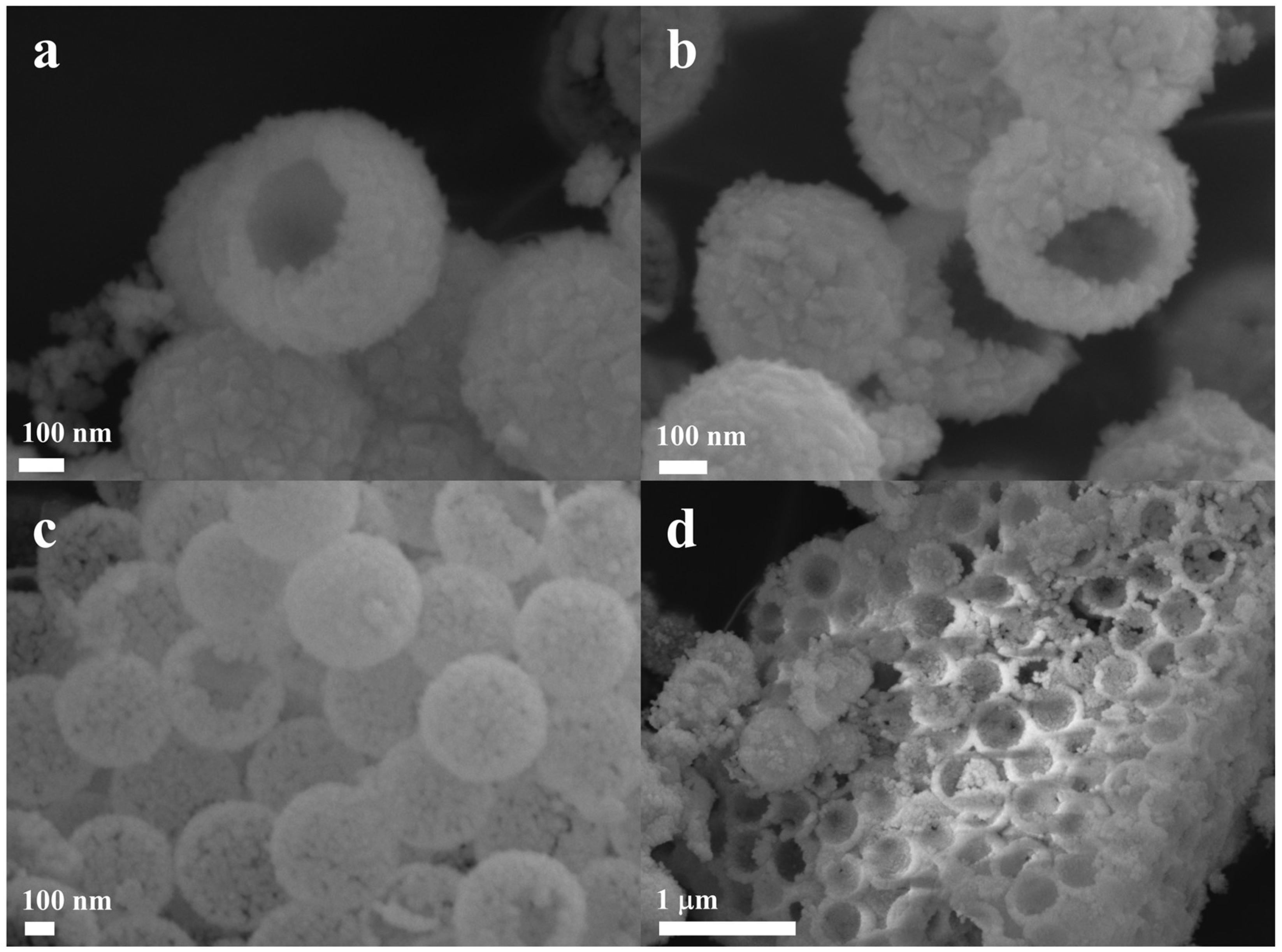
Figure 1. SEM images of (a) Ni/10CeO2-H, (b) Ni/8CeO2-H, (c) Ni/6CeO2-H, (d) Ni/4CeO2-H catalysts.
Nanomaterials 16 00868 g001
Figure 2. (a) Adsorption–desorption isotherms and (b) Pore size distributions of Ni/6CeO2-H, Ni/8CeO2-H, Ni/10CeO2-H and Ni/CeO2 catalysts.
Nanomaterials 16 00868 g002
Figure 3. (a) H2−TPR and (b) CO2−TPD profiles of Ni/6CeO2-H, Ni/8CeO2-H, Ni/10CeO2-H and Ni/CeO2 catalysts.
Nanomaterials 16 00868 g003
Figure 4. (a) CH4 conversion, (b) CO2 conversion, (c) molar ratio of H2/CO versus reaction temperatures over Ni/6CeO2-H, Ni/8CeO2-H, Ni/10CeO2-H and Ni/CeO2 catalysts; (d) CH4 conversion, (e) CO2 conversion, and (f) molar H2/CO ratio as a function of reaction time over Ni/6CeO2-H, Ni/8CeO2-H, Ni/10CeO2-H and Ni/CeO2 catalysts at 750 °C.
Nanomaterials 16 00868 g004
Figure 5. (a) TGA curves and (b) Raman spectra of the spent catalysts after long−term catalytic stability test.
Nanomaterials 16 00868 g005
Figure 6. XRD patterns of (a) fresh and (b) spent catalysts.
Nanomaterials 16 00868 g006
Figure 7. SEM images of (a) Ni/6CeO2-HS, (b) Ni/8CeO2-HS, (c) Ni/10CeO2-HS, (d) Ni/CeO2-S catalysts.
Nanomaterials 16 00868 g007
Figure 8. XPS spectra of Ni 2p3/2 and Ce 3d for fresh and spent catalysts: (a) Ni 2p3/2 of fresh catalyst, (b) Ni 2p3/2 of spent catalyst, (c) Ce 3d of fresh catalyst, (d) Ce 3d of spent catalyst.
Nanomaterials 16 00868 g008
Figure 9. CH4−TPSR profiles of (a) Ni/6CeO2-H, (b) Ni/8CeO2-H, (c) Ni/10CeO2-H and (d) Ni/CeO2 catalysts.
Nanomaterials 16 00868 g009
Figure 10. CO2−TPSR profiles of (a) Ni/6CeO2-H, (b) Ni/8CeO2-H, (c) Ni/10CeO2-H and (d) Ni/CeO2 catalysts.
Nanomaterials 16 00868 g010
Figure 11. In situ DRIFT spectra of reduced (a) Ni/6CeO2-H, (b) Ni/8CeO2-H, (c) Ni/10CeO2-H and (d) Ni/CeO2 catalysts.
Nanomaterials 16 00868 g011
Scheme 1. Schematic illustration of a proposed DRM reaction mechanism over reduced Ni/6CeO2-H catalysts.
Nanomaterials 16 00868 sch001
Table 1. Porous properties of Ni/6CeO2-H, Ni/8CeO2-H, Ni/10CeO2-H and Ni/CeO2.
CatalystsSpecific Surface Area 1
(m2 g−1)
Total Pore Volume 2
(cm3 g−1)
Pore Diameter 2
(nm)
Ni/6CeO2-H144.70.414.21
Ni/8CeO2-H105.30.344.36
Ni/10CeO2-H87.20.294.51
Ni/CeO281.60.266.12
1 Calculated by the Brunauer–Emmett–Teller (BET) method. 2 Determined by the Barrett–Joyner–Halenda (BJH) method from the desorption branch.
Table 2. XPS analysis of Ni 2p3/2 and Ce 3d.
CatalystsNi0/(Ni0 + Ni2+)Ce3+/(Ce4+ + Ce3+)
Ni/6CeO2-H0.630.350.21 (S)
Ni/8CeO2-H0.600.230.17 (S)
Ni/10CeO2-H0.480.180.14 (S)
Ni/CeO20.400.170.15 (S)
Disclaimer/Publisher’s Note: The statements, opinions and data contained in all publications are solely those of the individual author(s) and contributor(s) and not of MDPI and/or the editor(s). MDPI and/or the editor(s) disclaim responsibility for any injury to people or property resulting from any ideas, methods, instructions or products referred to in the content.