3.1. Raman Study of the TiO2–Based Structures
Raman spectra analysis is a powerful characterization technique that provides in-depth information on the crystalline lattice structure and molecular composition of the TiO
2-based samples. Raman spectroscopy has often been reported as a method used to study titanium dioxide samples containing impurities, including lanthanides [
29,
30,
31].
Here, we turn to both theoretical and experimental approaches for the complementary Raman study of titanium dioxide.
Table 2 compiles data on the band gap, bound distances, and lattice parameters of the theoretical models.
The characteristic peaks for anatase and rutile are presented in
Table 3. The Raman spectrum of anatase TiO
2 exhibits several active modes, including the prominent E
g mode with peaks around 144, 197, and 640 cm
−1 [
32,
33] resulting from the symmetric stretching vibration of O–Ti–O in TiO
2 [
34]. The E
g mode is sensitive to particle size, showing a blueshift and a broadening when nanoparticles are studied [
35,
36]. This size-dependent behavior is attributed to the three-dimensional confinement of phonons in finite-sized nanocrystals [
37]. Other notable modes are the B
1g mode with peaks around 519 and 399 cm
−1, and the A
1g mode with a peak around 513 cm
−1 [
32,
33]. The mentioned A
1g and B
1g peaks around 515 cm
−1 commonly form the doublet where B
1g relates to the symmetric bending vibration of O–Ti–O, and A
1g relates to its antisymmetric bending vibration [
38]. Furthermore, defects and stoichiometry also influence the Raman spectra. Iida and coauthors [
36] reported that Raman spectra are more sensitive to defects than XRD spectra.
The Raman spectrum of rutile TiO
2 exhibits peaks around 144, 447, 612, and 826 cm
−1, corresponding with the vibrational modes B
1g, E
g, A
1g, and B
2g, respectively [
39,
40]. In addition, the B
1g mode exhibits intriguing characteristics, including its relatively weak temperature dependence and broadening that can be attributed to the mode’s quartic anharmonicity and anomalous phonon–phonon interactions [
36]. The rutile spectrum also exhibits a distinct feature of pronounced second-order Raman scattering occurring around 240 cm
−1 [
41].
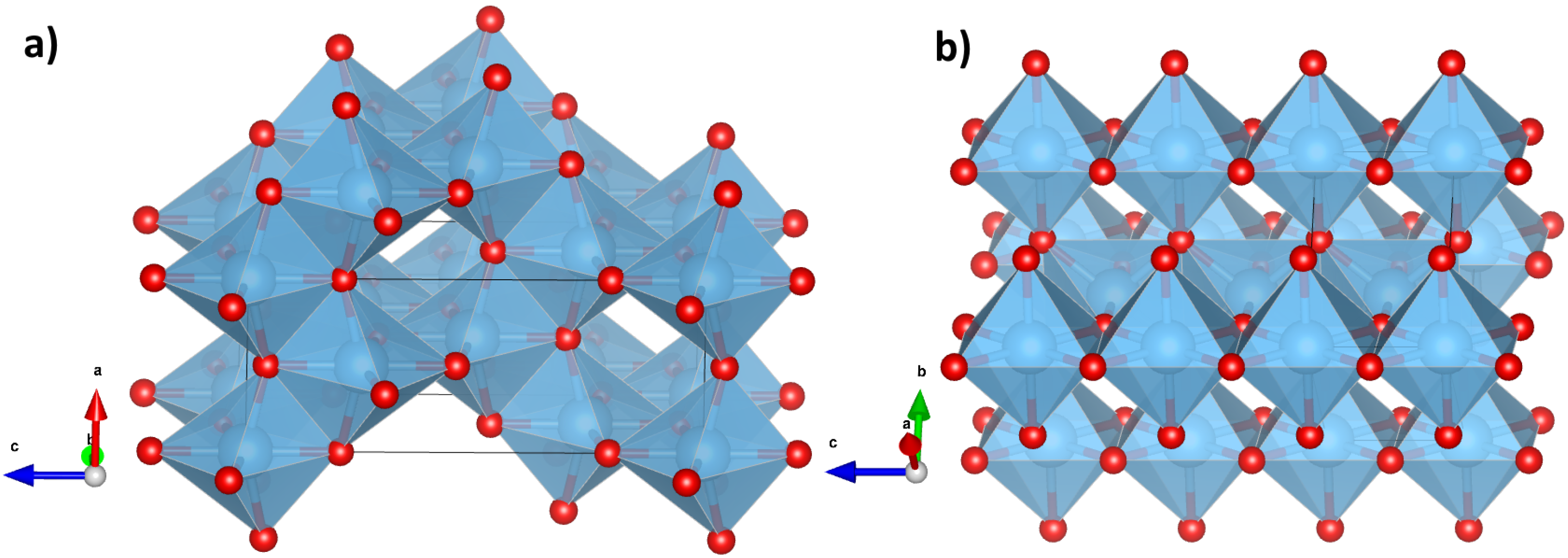
DFT calculations were performed to acquire Raman spectra of the bulk TiO
2 in the anatase and rutile phases as references for the further experimental Raman interpretation of the TiO
2 samples formed by different techniques [
40].
Table 2.
Band gap (
), lattice parameters (
a and
c), and bond distances (
d) for the fully relaxed TiO
2 structure calculated using the hybrid functional PBE0 [
25] and the computational code
Crystal23 [
24]. The parameter
represents the fraction of Hartree–Fock exchange. The calculated values are compared with the experimental data.
| | Polymorph | | a, Å | c, Å | , Å | , Å | , Å | , eV |
|---|
| Crystal23
| anatase | 0.25 | 3.779 | 9.553 | 1.9336 | 3.0452 | 2.4536 | 4.13 |
| | | | | | 1.9768 | 3.7786 | 2.7958 | |
| | rutile | 0.25 | 4.586 | 2.964 | 1.9455 | 2.9636 | 2.5213 | 3.93 |
| | | | | | 1.9822 | 3.5654 | 2.7775 | |
| | | | | | 3.4793 | | 2.9636 | |
| Experiment | anatase | | 3.785 [42] | 9.511 [42] | | | | 3.21 [43] |
| | rutile | | 4.592 [44] | 2.958 [44] | | | | 3.00 [43] |
3.1.1. DFT Calculations of Bulk TiO2 Raman Spectra
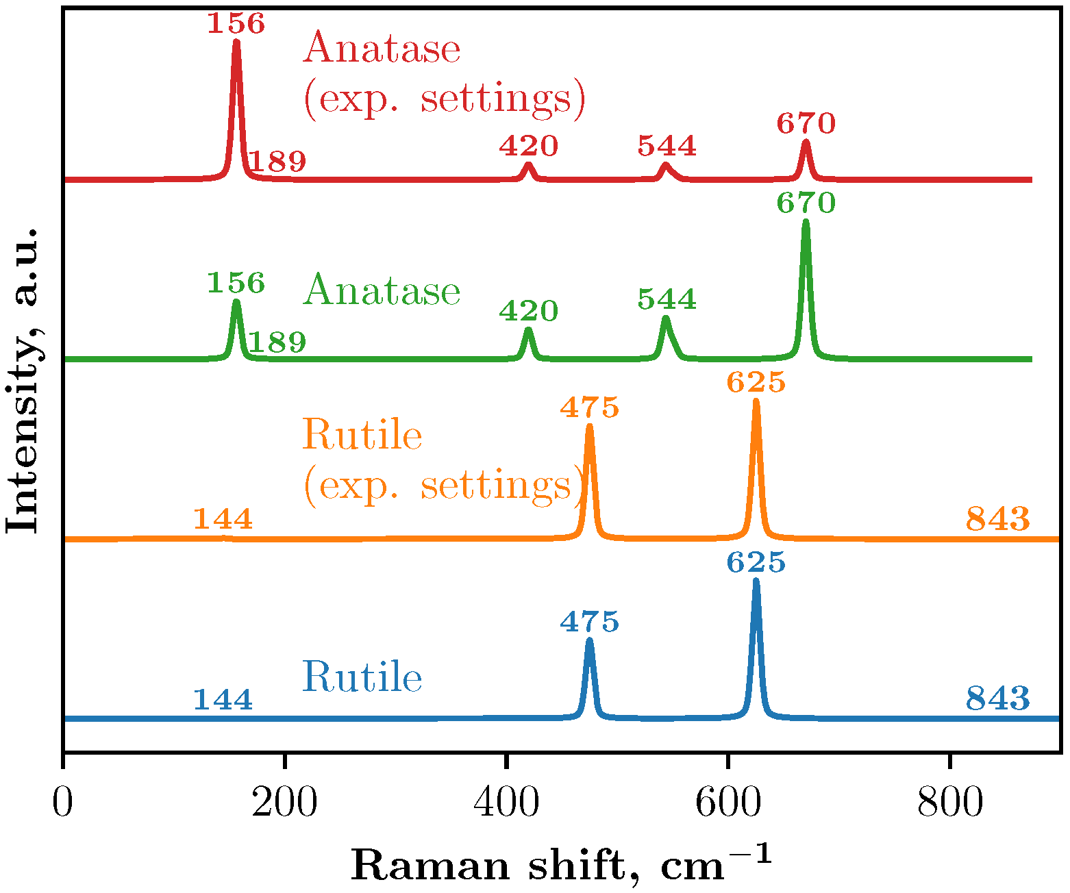
Raman spectra using a 2 × 2 × 3 supercell obtained from the DFT calculations are shown in
Figure 3. Two approaches were used to simulate the Raman spectra: with and without the experimental setup.
In
Crystal23, the keyword RAMANEXP involves the modification of the Raman intensity formula to account for experimental conditions. This model ensures that the intensities of the vibration modes match the experimental observations by incorporating the Bose distribution, account for the wavelength-dependent scattering efficiency, and average over orientations for comparison with powder sample experiments [
26]. In our calculations with the experimental setup, the temperature was set to 298.15 K and the wavelength to 525 nm.
In the Raman spectra of anatase, both calculations with and without the experimental setup yield identical peak positions, although the intensities differ. Five main peaks were identified in both cases (see
Table 3 and
Figure 3) and theoretical calculations incorporating the experimental setup produce peak intensities that align more closely with the experimental data obtained in this study and previous studies [
32,
33,
35,
39,
45]. The Raman spectra also correspond well with the study of Taudul et al. [
34]. This study employed
Crystal17 software with localized all-electron basis sets to calculate the vibrational properties and Raman spectra of anatase TiO
2. The calculations were performed using different exchange-correlation functionals, including PBE, PBEsol, PBE-D3, B3LYP, and PBE0, in combination with the DZVP and TZVP basis sets. Both basis sets include d-polarization functions for Ti and O atoms and f-polarization for Ti atoms. The PBE functional tends to underestimate frequencies, while PBE0, PBEsol, and B3LYP provide values closer to the experimental results. In another study [
46], the computations were performed with the ABINIT code, using pseudopotentials and a plane-wave basis set. The local density approximation (LDA) was applied for the exchange-correlation energy, and Teter-type extended norm-conserving pseudopotentials were used for titanium and oxygen.
Additionally, the vibrational properties for both TiO
2 polymorphs were investigated using first-principles DFT within the VASP by Frank et al. [
41]. The LDA and projector-augmented wave method were employed to model the electronic structure. The isotopic substitution of oxygen atoms was considered by adjusting the mass matrices, enabling the prediction of isotope-dependent frequency shifts. The calculated frequencies were validated by comparing them with the experimental Raman spectra acquired at temperatures as low as 5 K.
A similar pattern is observed in the Raman spectra of the rutile crystal: both calculations identify the same peak positions but with differing intensities. In this case, four peaks were identified (see
Table 3). These results correlate well with Ref. [
40], where computational modeling of the Raman spectra for the rutile polymorph was carried out using the GULP software package and the Buckingham interatomic potential, and the phonon frequencies and line widths were determined through the Fourier transform of the velocity autocorrelation function, as well as with Ref. [
47] where Raman spectroscopy characterization of rutile nanocrystals embedded in cluster-assembled TiO
2 films was performed. Separately, we note that some peaks on the graph have low intensity, and their presence was verified through the analysis of the Raman active modes listed in the output of the
Crystal23 calculations.
Table 3.
Identification of calculated anatase and rutile bulk Raman spectra peaks and comparison with previous experimental measurements of anatase and rutile bulk.
Table 3.
Identification of calculated anatase and rutile bulk Raman spectra peaks and comparison with previous experimental measurements of anatase and rutile bulk.
| Phase | Calculated, cm−1 | Calculated in Another Study, cm−1 | Experimental Values | Assignment |
|---|
| Anatase | 156.5 | 122.97–146.51 [34], 145.6 [46] | 144 [32], 143 [33], 144 [35], 147 [39], 144 for [41], 144 [45] | Eg [32,41,45] |
| 189.5 | 169.88–194.66 [34], 171.1 [46] | 197 [32], 198 [33], 200 [35], 198 [39], 196 for [41], 197 [45] | Eg [32,41,45] |
| 419.6 | 368.84–413.70 [34], 398.4 [46] | 399 [32], 395 [33], 397 [35], 398 [39], 394 for [41], 400 [45] | B1g [32,41,45] |
| 550.6 | 497.84–535.76 [34], 518.4 [46] | 519 at 73 K [32], 512 [33], 516 [35], 515 [39], 516 for [41], 515 [45] | B1g [32,41,45] |
| 543.3 | 486.79–524.54 [34], 535.9 [46] | 513 at 73 K [32], 518 [33], 516 [35], 515 [39], 516 for [41], 519 [45] | A1g [32,41,45] |
| 669.9 | 606.67–646.00 [34], 662.1 [46] | 639 [32], 639 [33], 639 [35], 640 [39], 638 for [41], 640 [45] | Eg [32,41,45] |
| Rutile | 143.7 | 169 [40], 141.2 for [41] | 144 [39], 143 [40], 145 for [41], 143 [48], 142 [49] | B1g [39,40,41] |
| 474.9 | 400 [40], 466.3 for [41] | 448 [39], 447 [40], 448 for [41], 447 [48], 439 [49] | Eg [40,41,50] |
| 625.0 | 558 [40], 614.6 for [41] | 612 [39,40,48], 613 for [41], 608 [49] | A1g [39,40,41,50] |
| 843.2 | 803 [40], 819.1 for [41] | 827 [39], 826 [40], 826 for [41], 826 [48], 810 [49] | B2g [39,40,41] |
3.1.2. Raman Spectroscopy of the Pure TiO2 Samples
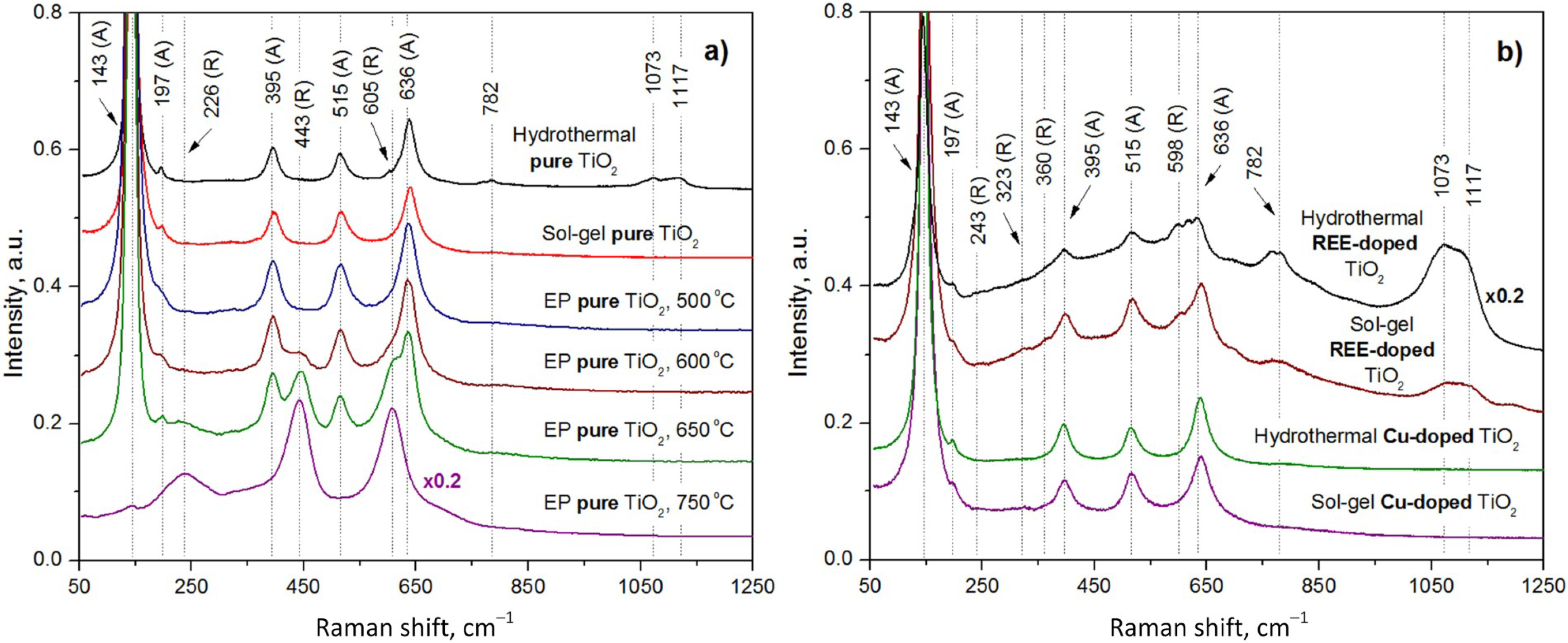
The experimentally measured Raman spectra of the pure TiO
2 samples synthesized by the EP, hydrothermal, and sol–gel methods are shown in
Figure 4a.
We investigated four samples synthesized by the EP method at different annealing temperatures to reveal a heating effect on the TiO
2 phase and molecular composition. The sample annealed at the lowest temperature (500 °C) comprises only the anatase phase with the corresponding peaks at 143, 197, 395, 517, and 636 cm
−1 (see
Table 3). The increase in temperature led to a gradual conversion to the rutile phase as seen in
Table 4. In more detail, the TiO
2 sample annealed at 600 °C is characterized by the Raman spectrum with anatase peaks (143, 192, 395, 515, and 634 cm
−1) and the peak of rutile E
g at 440 cm
−1. This indicates a small amount of the rutile crystallites in the sample. (It should be specifically noted that the B
1g rutile peak near 145 cm
−1 cannot be used for the verification of phase transformations, as it is obscured by the much more intense anatase E
g peak located in the same region). The Raman spectrum of TiO
2 heated to 650 °C also contains the characteristic bands of anatase, but peaks are observed at 226 (second-order Raman scattering [
41]), 443 (E
g), and 605 (A
1g) cm
−1, which means a tendency to formation of the rutile phase. At the highest annealing temperature (750 °C), the anatase phase completely transformed into the rutile one.
The temperature dependence of the structure of the sol–gel and pure hydrothermal TiO
2 samples has already been reported elsewhere [
51,
52], unlike the EP TiO
2 samples, which have been studied to a lesser extent. Therefore, we avoided repeating the determination of the temperature effect on the Raman spectra of the pure TiO
2 samples formed by the sol–gel and hydrothermal methods. It should be noted that the transition from anatase to rutile, associated with an increase in annealing temperature, is the same for TiO
2 formed by each of the methods, as shown by a comparison of our data for the EP TiO
2 sample and the previously reported results for hydrothermal and sol–gel TiO
2 samples.
The pure sol–gel TiO2 annealed at 400 °C exclusively contains the anatase phase, as evidenced by peaks at 144, 196, 395, 518, and 639 cm−1.
A slight increase in the annealing temperature to 500 °C of a pure hydrothermal TiO2 resulted, as expected, in a small rutile content expressed by an additional Raman band at 605 cm−1.
Weak peaks at 782, 1073, and 1117 cm
−1 were detected exclusively in the hydrothermal TiO
2 sample, but not in those synthesized by the sol–gel or extraction–pyrolytic methods, underscoring their uniqueness to the hydrothermal synthesis. According to the literature, the peaks around 782, 1073, and 1117 cm
−1 correspond to vibrations of the C–H, C–O, and C–C groups [
53,
54,
55,
56], which can be caused by the adsorption of organic molecules on the TiO
2 surface from air, as well as signifying that the samples are not completely washed of products of TTIP decomposition. These peaks can be indirect evidence of differences in the surface structure of the samples. In particular, the hydrothermal TiO
2 sample is likely to have a higher particle package density and larger specific surface area, capable of holding or capturing undesirable contaminations from the reaction solutions and environment, while the sol–gel and EP TiO
2 samples supposedly have similar surface morphology.
3.1.3. Raman Spectra Analysis of REE-Doped TiO2 Samples
In this study, we modified the TiO2 samples with dopants of REEs (Yb and Er) and Cu (as observed in the next subsection). The Raman spectra of pure sol–gel, hydrothermal, and EP samples annealed at 400–500 °C were found to have nearly the same Raman band positions in the 300–700 cm−1 range. However, the hydrothermal sample is characterized by additional Raman bands at larger wave numbers, which means that its structure differs from those of the sol–gel and EP samples. Therefore, the effect of doping was studied only in sol–gel and hydrothermal TiO2 samples.
The Raman spectra of the REE-doped TiO
2 samples reveal the presence of both the anatase and rutile phases, regardless of whether the samples were synthesized using the hydrothermal or sol–gel method (see
Table 5).
For the sol–gel samples annealed at 500 °C, two different REE Yb:Er ratios were investigated—one sample had a Yb:Er volume ratio of 17.3:1, while the other had a ratio of 17.4:1. Initially, we expected to observe a redshift in the Raman spectrum peaks with an increase in the REE-dopant concentration, but the Raman spectra of the two samples were nearly identical.
Thereby, we presented only the Raman spectrum of the REE-doped TiO
2 sample with a 17.3:1 volume ratio of Yb and Er in
Figure 4. The peaks of the anatase phase are observed at 146, 196, 398, 517, and 640 cm
−1, while the peaks of the rutile phase are located at 243, 323, 360, and 598 cm
−1.
A Ti–OH vibration peak is identified at 702 cm
−1. The peaks attributed to the vibrations of the C–H, C–O, and C–C groups [
53,
54,
55] are observed at 770, 1093, and 1124 cm
−1. The presence of rutile peaks indicates that an increased annealing temperature (500 °C vs. 400 °C for the pure sample) initiated the transformation of the anatase phase into rutile.
For the hydrothermal REE-doped sample (Yb:Er = 17.5:1), Raman analysis revealed anatase peaks at 144, 196, 395, 518, and 633 cm−1, and rutile peaks at 237 and 597 cm−1. A peak at 701 cm−1 is attributed to Ti–OH vibrations. The peaks at 769 cm−1, 1076, and 1115 cm−1 corresponding to C–H, C–O, and C–C vibrations show an increased intensity compared to the sol–gel REE-doped sample. This must be caused by a larger amount of organic contaminants remaining in the hydrothermal sample due to a lower annealing temperature.
In general, Raman spectra reveal a higher overall intensity for hydrothermal REE-doped TiO2 compared to sol–gel samples, with a lower rutile phase concentration due to a higher amount of REE-dopants. Both synthesis methods show higher rutile phase concentrations in REE-doped samples than in the pure TiO2 powders. However, higher REE concentrations reduce the rutile phase content, which is consistent with that of sol–gel REE-doped samples.
Additionally, the hydrothermal powder shows significantly stronger peaks at 769, 1076, and 1115 cm−1, indicating a higher concentration of organic contaminations compared to the sol–gel sample.
3.1.4. Raman Spectra Analysis of Cu-Doped TiO2 Samples
The Cu-doped TiO
2 samples synthesized by hydrothermal and sol–gel methods were also characterized by Raman spectroscopy (see
Table 6).
The Raman spectrum of the sol–gel Cu-doped TiO2 sample showed only the peaks of the anatase phase at 147, 195, 396, 515, and 640 cm−1. Similarly, the Cu-doped TiO2 sample obtained by the hydrothermal method exhibited only the anatase phase with corresponding peaks at 145, 197, 395, 515, and 638 cm−1.
The intensity of the Raman spectrum is higher in the hydrothermal Cu-doped TiO2 sample compared to the sol–gel sample, which matches the results obtained for both the pure and REE-doped TiO2 samples. We suppose that it can be caused by the higher packing density of the hydrothermal TiO2 in contrast to the sol–gel method.
In both the sol–gel and hydrothermal Cu-doped TiO2 samples, only the anatase phase is visible. These results for the Cu-doped TiO2 samples contrast with the findings for the pure and REE-doped TiO2 samples, where rutile phase peaks were revealed. Rutile phase peaks were observed only in the hydrothermal method for pure TiO2 samples and in both the sol–gel and hydrothermal methods for REE-doped TiO2 samples. In the case of the sol–gel REE-doped TiO2 sample, the rutile phase appears due to the higher annealing temperature of the sample compared to the pure sol–gel TiO2 sample. The absence of rutile phase peaks in the Cu-doped TiO2 samples can be attributed to a combination of doping effects rather than solely annealing conditions. One possible explanation for why Cu specifically inhibits rutile phase formation is that Cu ions stabilize anatase by affecting the crystallization process, likely due to their ionic radius and interaction with the TiO2 lattice. Cu doping may induce lattice strain or grain boundary effects that suppress the anatase-to-rutile transition, whereas REE doping promotes it, possibly due to differences in ionic size and charge compensation mechanisms.
Furthermore, in the case of the Cu-doped TiO2 samples, the C–H, C–O, and C–C group peaks are absent for both sol–gel and hydrothermal samples. For pure TiO2 powders, these peaks were observed only in the hydrothermal sample, while REE-doping resulted in the formation of the powders with organic residues in both sol–gel and hydrothermal samples. The intensity of the corresponding Raman peaks was more intensive for the hydrothermal powder than for the sol–gel one.
3.2. Characterization of the TiO2 Morphology by SEM
All samples after synthesis and collection from laboratory glassware were powders with different dispersions. At the same time, hydrothermal powders were visually finer than sol–gel ones. Due to the fine dispersion, the hydrothermal powders were also denser. This observation is confirmed by the results of SEM analysis. The differences in morphology of the TiO
2 particles synthesized by sol–gel and hydrothermal methods were revealed, as illustrated in
Figure 5 where the SEM images and histograms of the particle size distribution are shown. It is seen that both hydrothermal and sol–gel powders consist of large agglomerates of 10 to 150 µm (see SEM images with a scale of 200 µm). At the same time, many agglomerates in hydrothermal samples have the form of plates with sharp edges and tips. Sol-gel agglomerates, in contrast, have a more rounded shape. The packing density of hydrothermal powders, as expected, is higher than that of sol–gel powders. Higher resolution SEM analysis of the powders showed that the agglomerates consist of nanoparticles ranging in size from a few nanometers to 70 nm (see SEM images with a scale bar of 400 nm and histograms). It is important to note that the hydrothermal agglomerates have a more uniform surface area on their faces, and the nanoparticles are densely packed in them. In the subsection on Raman analysis, we assumed that these structural features may result in favoring the adsorption of foreign molecules from the environment. We saw that the presence of Raman bands in the region of 700–1200
was not characteristic of all hydrothermal samples. Copper-doped titanium oxide synthesized hydrothermally does not contain peaks in this range, nor does the sol–gel one. On the other hand, both hydrothermal and sol–gel REE-doped powders have strongly pronounced Raman bands corresponding to the C–H, C–O, and C–C groups. The same samples are characterized by larger nanoparticle sizes up to 60–70 nm in contrast to the maximum 40–45 nm of the pure and copper-doped samples. At the same time, the pure hydrothermal sample with low-intensity Raman bands in the 700–1200
range also has a slightly larger nanoparticle size compared to the pure sol–gel and copper-doped samples. This follows from its size histogram, which has a lower intensity of bars for sizes less than 20 nm. It can be concluded that samples with larger nanoparticles tend to collect molecules from the environment on their surface, which are harder to wash away from chemical reaction products. On the contrary, it is generally accepted that smaller structures should better adsorb molecules due to their large specific surface area. However, in this case, the size of pores between nanoparticles, which is larger and allows the capture of high molecular compounds, is obviously of dominant importance. Also, apparently, the by-products of the reactions are inside the larger nanoparticles, being washed out from the surface only, while smaller nanoparticles with a larger specific area are cleaned much better during washing.
3.3. EDX Elemental Analysis of TiO2 Samples
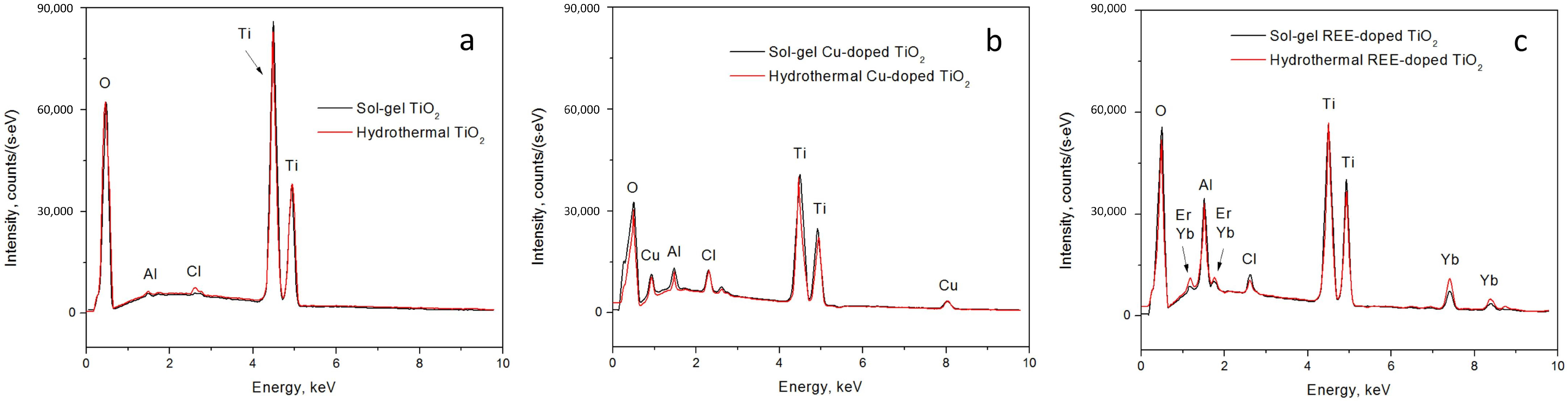
Then, the EDX spectra of both the pure and doped sol–gel and hydrothermal TiO
2 samples were collected (
Figure 6). The intensity of peaks in EDX spectra reflects both the relative quantity of specific atoms in the sample and the distribution of elements within the material, such as the depth at which different dopants are located. This is particularly interesting for comparisons of the TiO
2 samples synthesized by sol–gel and hydrothermal methods.
In the case of pure TiO
2 synthesized through the sol–gel method, we observed a characteristic oxygen (O) peak at approximately 0.5 keV, two titanium (Ti) peaks at around 4.5 keV and 5 keV, and peaks at approximately 1.5 keV and 2.7–2.8 keV, which are not typical for TiO
2. Identifying the origin of these unknown peaks has proven challenging, as no prior publications provide a precise identification of these peaks in EDX spectra of pure TiO
2. However, certain studies have attributed these peaks to aluminum (Al) [
57,
58,
59] and chlorine (Cl) [
60,
61,
62]. As a rule, the peaks of aluminum in the EDX spectra are neglected, since they are caused by the signal from the pin stubs for the sample mounting in the SEM chamber. The presence of chlorine in the samples may be due to the use of hydrochloric acid in one of the processes of titanium oxide synthesis. Chlorine is probably not completely washed out of the hydrothermal samples. In the sol–gel samples, chlorine is most likely present due to its adsorption from the air in the fume hood.
When examining the TiO
2 sample synthesized by the sol–gel method with REE dopants, we observed that the peaks at approximately 1.8 keV, 7 keV, and 7.5 keV corresponded to Yb and Er. The peak around 1.8 keV is commonly associated with either erbium (Er
3+) or ytterbium (Yb
3+). Consequently, Er
3+ is expected at approximately 7 keV, and Yb
3+ should be detected around 7.5 keV [
63,
64,
65].
In the context of the TiO
2 sample synthesized by the sol–gel method with the Cu dopant, we observe prominent peaks at approximately 1 keV and 8 keV, indicative of the presence of Cu [
66,
67,
68]. In the EDX spectra, a distinct peak at approximately 2.4 keV is observed, signifying the presence of sulfur (S) [
69,
70,
71], which again remained in the sample due to incomplete washing of the reaction products and, in particular, from the acidic residue of copper sulfate. The peaks of aluminum and chlorine are also present in the EDX spectra of all doped samples, as in the case of the pure powders at 1.5 and 2.7–2.8 keV, respectively.
The primary distinction between the sol–gel and hydrothermal TiO2 samples lies in the intensity of the EDX spectra. Overall, the intensity of the EDX spectra is higher for the sol–gel TiO2 samples compared to the hydrothermal TiO2 ones, for both the pure TiO2 and REE- and Cu-doped TiO2 samples. This difference may be attributed to the sol–gel sample having a smoother agglomerate surface than the hydrothermal samples.
In the case of pure TiO2, the peaks for Al and Cl inclusions are much more prominent for the hydrothermal sample than for the sol–gel sample.
For the REE-doped TiO2 samples, the situation is reversed compared to the pure samples. Although the intensity of the Cl peak becomes relatively identical for both the sol–gel and hydrothermal samples, the intensity of the Al peak is significantly higher for the sol–gel sample than for the hydrothermal sample. Furthermore, the intensity of the REE dopant peaks (Er, Yb) is more prominent in the hydrothermal sample TiO2 than in the sol–gel sample.
Similarly, in the case of Cu-doped TiO2, the situation reflects that of the REE-doped samples. The intensity of the Cl peak is relatively similar for both the sol–gel and hydrothermal samples, while the Al peak is more prominent for the sol–gel sample. The S peak is more intense for the hydrothermal sample. Like the REE-doped TiO2 samples, where the REE dopant peak intensity was higher for the hydrothermal sample, in the case of the Cu-doped sample, the Cu dopant peaks are also more intense for the hydrothermal sample than for the sol–gel sample.
In summary, the EDX spectra intensity is higher for the sol–gel TiO2 samples. The Al and Cl peak intensity in the case of the pure TiO2 samples is higher for the hydrothermal sample, while after doping (observed for both REE and Cu dopants), the situation is reversed, as these peaks become more intense for the sol–gel sample. Meanwhile, the dopant (both REE and Cu) peaks are more prominent for the hydrothermal samples. The variation in the intensity of peaks can be reasoned by either the concentration of the elements in the TiO2 powders or the EDX measurement errors.
3.4. XPS Surface Composition Analysis of TiO2 Samples
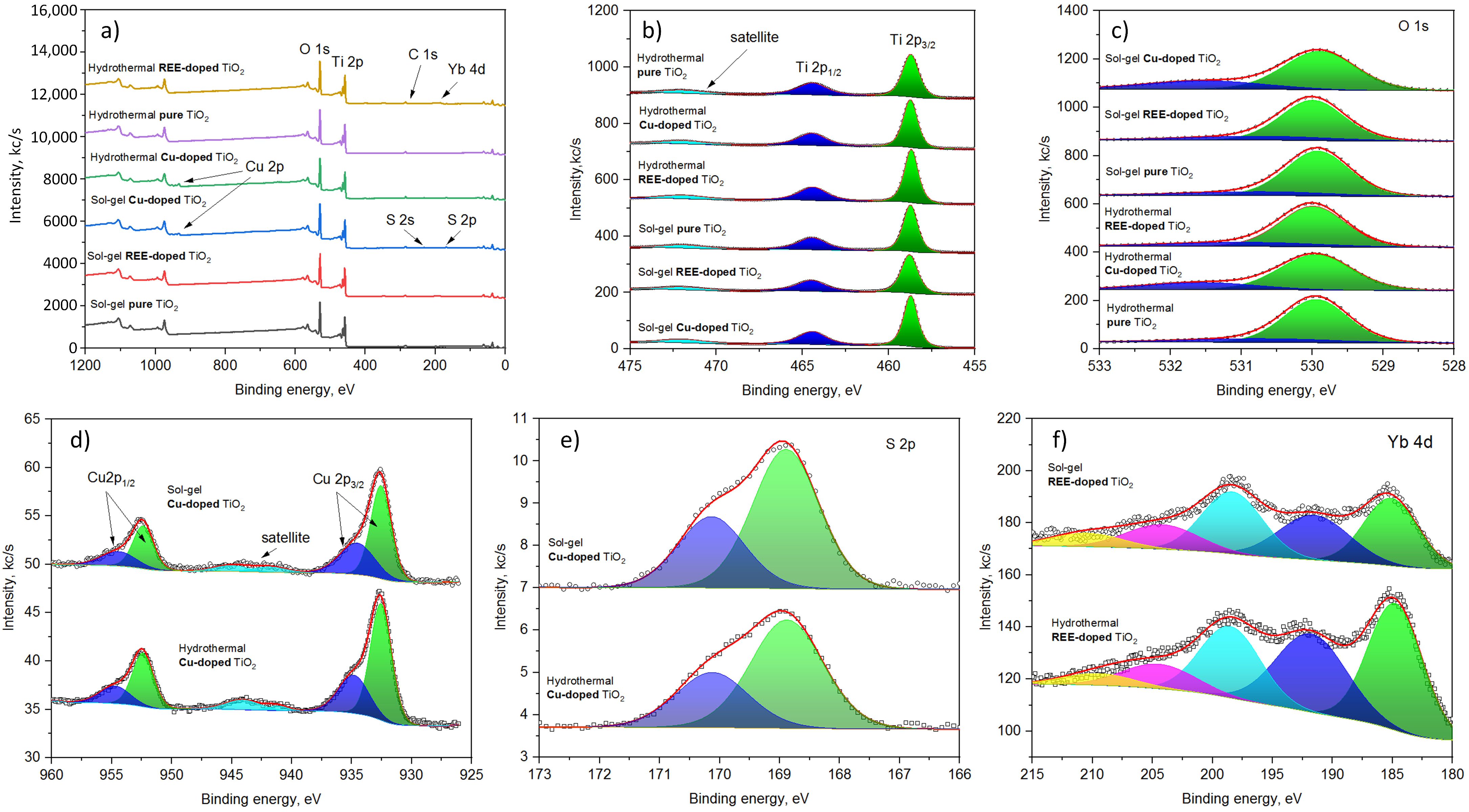
The XPS survey spectra are shown in
Figure 7a. The main bands corresponding to Ti 2p, O 1s, Cu 2p, S 2p, and Yb 4d have been identified and measured at a higher resolution, as depicted in
Figure 7a–e.
The spectra of Ti 2p contain bands at 458.7 eV, 464.5 eV, and 472.0 eV corresponding to 2
, 2
, and satellite features (
Figure 7a). The spectral positions of the bands are identical for all samples studied and are attributed to
[
72].
The spectra of O 1s for different samples are similar (
Figure 7b); they contain a strong signal at 529.9 eV (Ti-O) and small intensity bands in the range of 531.2–531.6 eV, corresponding to surface oxidation and hydroxyl groups [
73].
The signal of copper for sol–gel and hydrothermally synthesized samples is also characterized by almost the same pattern (
Figure 7c). They contain two groups of peaks that appear in the range of 933 eV (Cu 2
) to 955 eV (Cu 2
). Additionally, a smaller intensity signal present in the range of 940–945 eV corresponds to satellite features. The position and relative intensity of the satellite feature suggest that both
- and
-containing compounds are present in the material [
74,
75].
The detailed analysis of the Cu 2
region reveals the peaks present at 932.6 eV and 935.0 eV (hydrothermal) and 932.6 eV and 934.6 eV (sol–gel). The smaller energy peaks correspond to to copper oxide, while the higher intensity peaks correspond to
[
76]. The latter is supported by the sulfur signal present in the spectra of the copper-containing samples at 168.9 eV (2
) and 170.1 eV (
) that correspond to sulfate groups (
Figure 7e) [
77].
The detailed analysis of Yb 4d spectra reveals a complex structure of signals, with peaks appearing at 184.7 eV (185.1 eV), 191.7 eV (191.6 eV), 198.5 eV (198.4 eV), 204.5 eV (204.2 eV), and 210.0 eV (210.5 eV) for hydrothermal (sol–gel) samples. The spectral positions of the principal components suggest that the dominant valence state of Yb is 3+ [
78].


 ,
, 


