Article

Bi2MoO6 Embedded in 3D Porous N,O-Doped Carbon Nanosheets for Photocatalytic CO2 Reduction

1
The Institute of Technological Sciences, Wuhan University, Wuhan 430072, China
2
School of Chemistry and Chemical Engineering, Harbin Institute of Technology, Harbin 150080, China
*
Authors to whom correspondence should be addressed.
These authors contributed equally to this work.
Nanomaterials 2023, 13(9), 1569; https://doi.org/10.3390/nano13091569
Submission received: 21 March 2023 / Revised: 26 April 2023 / Accepted: 5 May 2023 / Published: 6 May 2023
(This article belongs to the Special Issue Nanostructured Materials for Carbon Neutrality)

Abstract

:
Artificial photosynthesis is promising to convert solar energy and CO2 into valuable chemicals, and to alleviate the problems of the greenhouse effect and the climate change crisis. Here, we fabricated a novel photocatalyst by directly growing Bi2MoO6 nanosheets on three-dimensional (3D) N,O-doped carbon (NO-C). Scanning electron microscopy (SEM) and transmission electron microscopy (TEM) show that the designed photocatalyst ensured the close contact between Bi2MoO6 and NO-C, and reduced the stacking of the NO-C layers to provide abundant channels for the diffusion of CO2, while NO-C can allow for fast electron transfer. The charge transfer in this composite was determined to follow a step-scheme mechanism, which not only facilitates the separation of charge carriers but also retains a strong redox capability. Benefiting from this unique 3D structure and the synergistic effect, BMO/NO-C showed excellent performance in photocatalytic CO2 reductions. The yields of the best BMO/NO-C catalysts for CH4 and CO were 9.14 and 14.49 μmol g−1 h−1, respectively. This work provides new insights into constructing step-scheme photocatalytic systems with the 3D nanostructures.

1. Introduction

It is well known that we have advanced from an industrialized era to an information era. One of the grand challenges in this new era is to reduce the emission of greenhouse gases, which are mainly due to the excessive consumption of fossil fuels [1,2,3]. Climate change has posed a threat to the ecosystem that human beings, caused by the gradual increase of the concentration of CO2 [4,5], which arises from industrial emissions and excessive burning of fossil fuels [6,7]. To mitigate the increasing concentration of CO2 in the atmosphere, one effective strategy is to photocatalytically convert CO2 to valuable solar fuels, such as hydrocarbons [8,9,10], which provide a viable solution for future energy storage and supply [11].
Carbon materials possess considerable microstructural and electrical properties [12], and are facile to synthesize, making them one of the excellent substrate materials for a wide range of applications [13,14]. Carbon materials serve as an excellent substrate to support exotic catalysts due to their thin layer structure and excellent electron transport ability [15], and N atom-doped carbon materials not only prevent catalyst aggregation but also provide higher conductivity and expose more active sites [16,17].
Unfortunately, the rapid recombination of photogenerated electrons and holes limits the applications of graphitic materials for the photocatalysis [18,19]. Some methods have been developed to overcome this problem, including doping with metallic and nonmetallic elements, mixing with metal oxides or metal sulfides, heterostructure constructions, and morphology modification [16,17,18,19]. Moreover, Liu et al. proposed that the energy band structure of the material is tuned by the construction of heterojunctions [19,20]. Christoffer et al. employ ab initio molecular dynamics (AIMD) simulations to demonstrate that the loaded Bi-containing material not only maintains and promotes the topological insulating properties but also improves the original band gap [21].
Bismuth molybdate (Bi2MoO6) as a typical n-type semiconductor, which possesses a remarkable layered structure and a proper band gap (2.5~2.7 eV) [22,23], is often used to construct heterostructures with other semiconductors to achieve the promotion of photoinduced electron-hole pair separation and to improve the photocatalytic performance of heterostructured materials. In this work, a CO2RR photocatalyst was fabricated by uniformly dispersing Bi2MoO6 (BMO) nanosheets on 3D N-doped graphitic carbon (NO-C), using a solvent thermochemical synthesis method, and the design is shown in Scheme 1. The direct growth of Bi2MoO6 nanosheets on 3D NO-C effectively prevents the restacking of NO-Cs. Furthermore, the unique 3D contact and coupling are favorable for carrier separation, and provide effective channels for rapid electron transfer, further increasing the charge transfer rate of the material under photoexcitation. The optimized BMO/NO-C-7 catalyst gives good CH4 yield, and high CO selectivity, with strong CO2 reduction efficiency and stability after 35 h.

2. Experimental Section

Supporting information gives the details of experiments, materials characterizations, electrochemical tests, and DFT calculations.

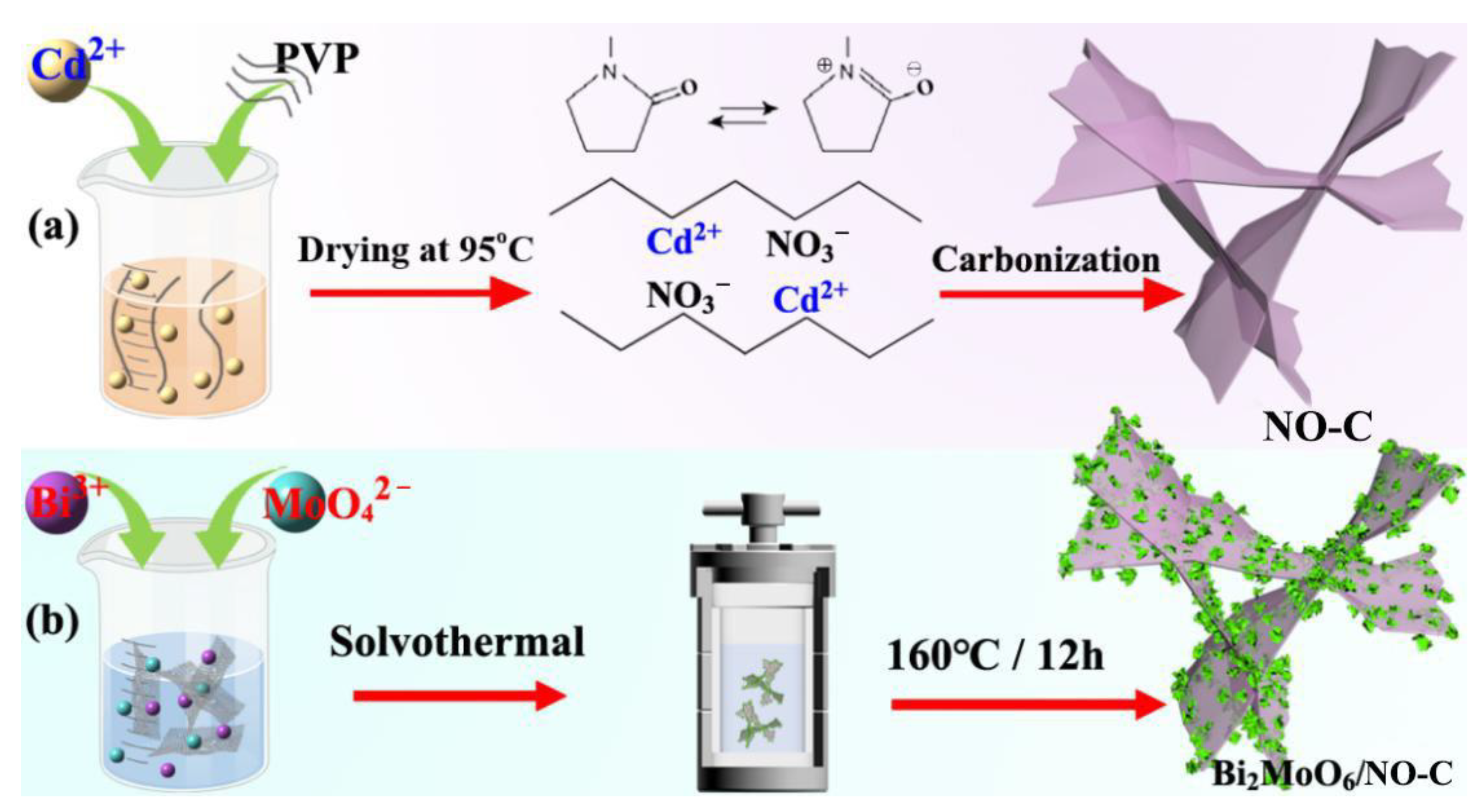
2.1. Preparation of the Ultra-Thin NO-C Nanosheets

The method used to fabricate the ultra-thin 3D NO-C nanosheets was based on a previous report [23,24]. Firstly, the PVP-Cd2+ precursor was formed by dissolving 1.0 g of PVP in 30 mL of DI water and adding 1.5 g of Cd(NO3)2·6H2O. The mixture was stirred at room temperature to ensure it was homogeneous. The solution was then dried in an oven at 95 °C to form the precursor. Subsequently, the precursor was heated up to 1000 °C in a tube furnace that was protected by an N2 atmosphere, with a heating rate of 5 °C min−1 (The N2 flow rate is 80~100 mL·min−1). Finally, the ultra-thin 3D NO-C nanosheets were obtained by carbonization at 1000 °C for 1 h.

2.2. Preparation of BMO/NO-C Composites

The synthesis of Bi2MoO6/NO-C (BMO/NO-C) was accomplished by a solvent thermochemical method [25]. Initially, a clear and transparent solution was formed by mixing Bi(NO3)2·5H2O (0.6 mmol) and Na2MoO4·H2O (0.3 mmol) in ethylene glycol (5 mL). After stirring for an hour, 30 mL of ethanol was added to the mixture, and the NO-C (50, 70, 90 mg) was incorporated and stirred for an additional hour. Finally, the mixed solution was heated for 12 h in a sealed autoclave at 160 °C. The resulting products were washed repeatedly with ethanol and allowed to dry. The products were named BMO/NO-C-5, BMO/NO-C-7, and BMO/NO-C-9, according to the quantity of NO-C that was added to the mixture.

3. Results and Discussions

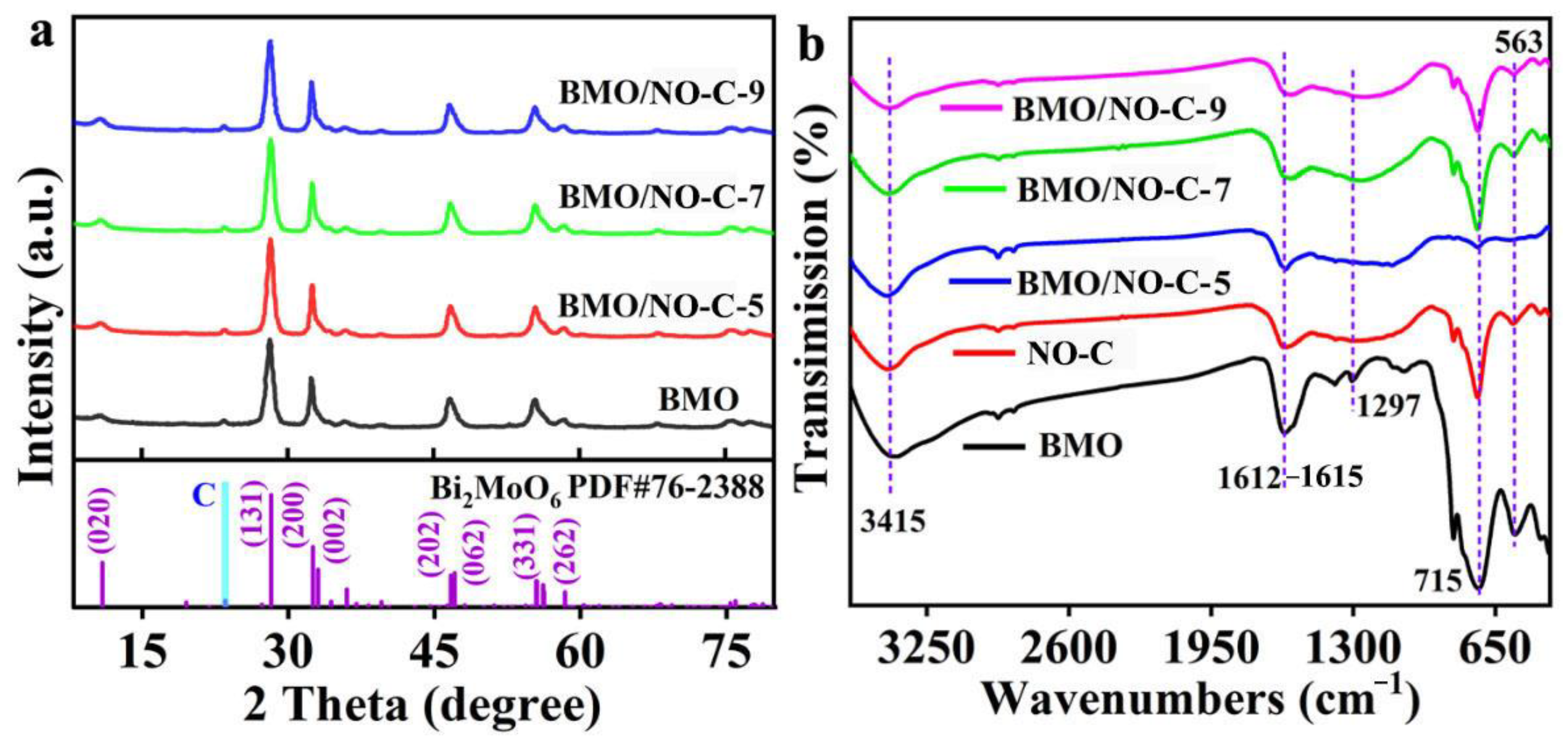
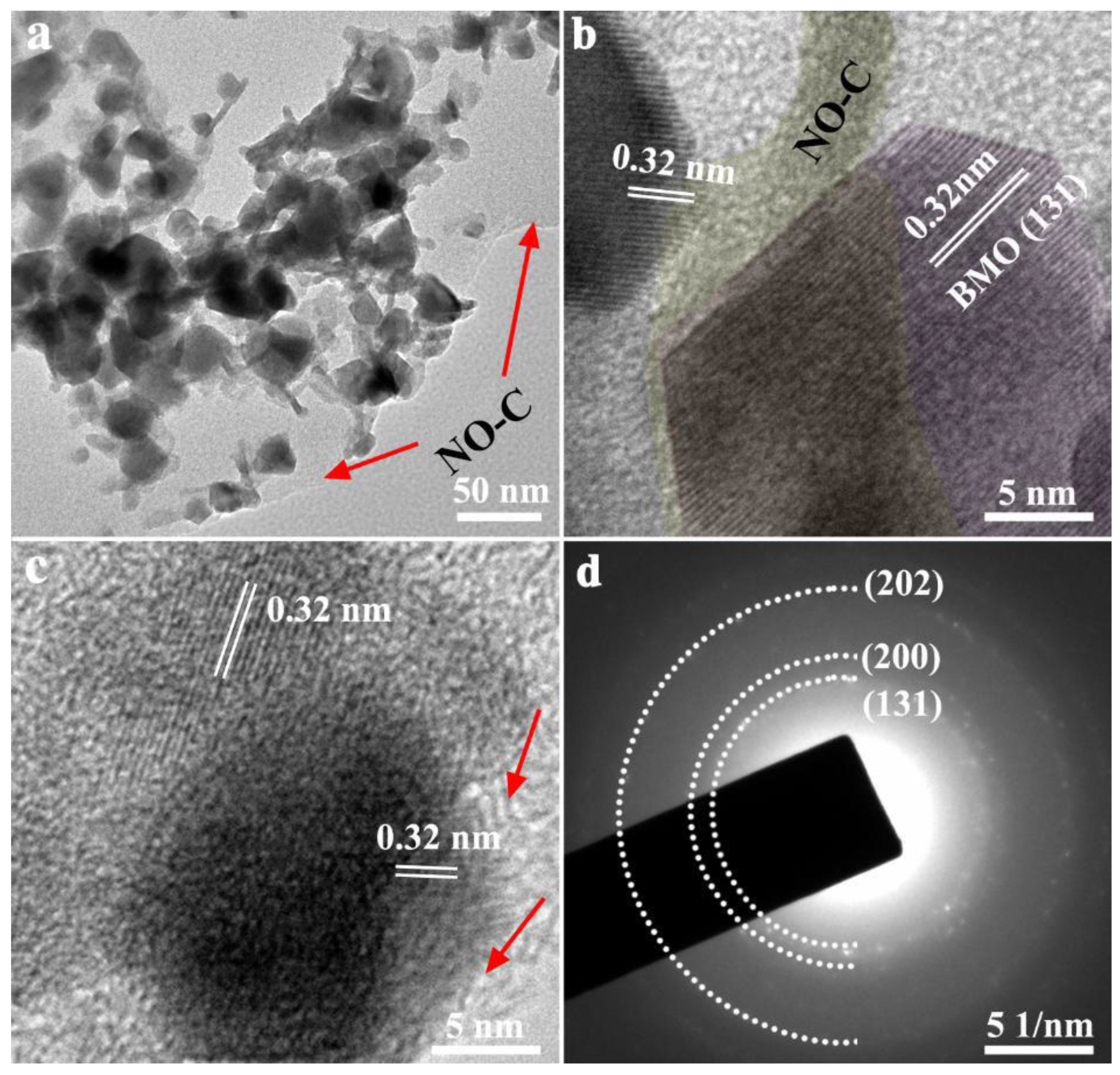
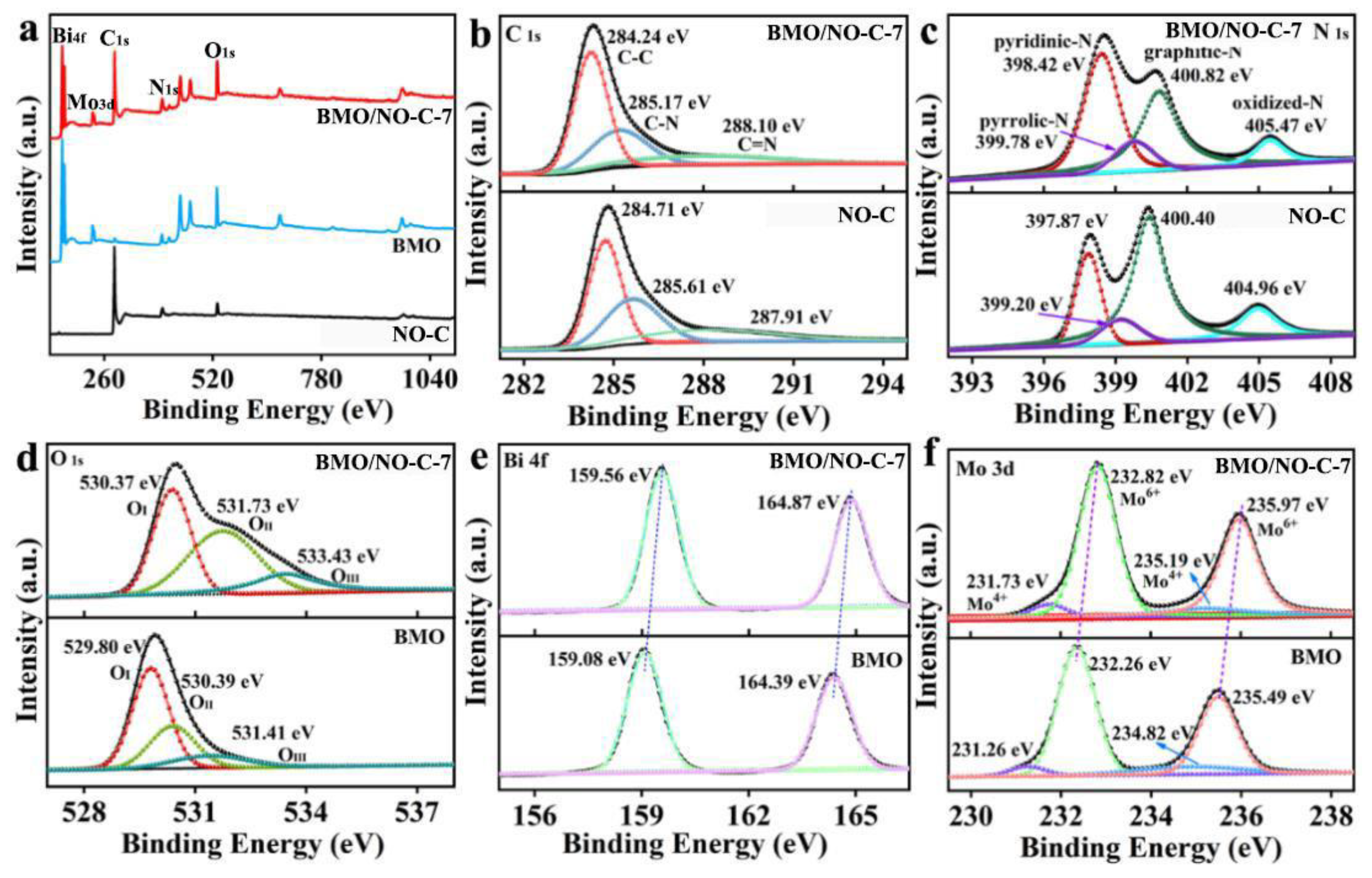
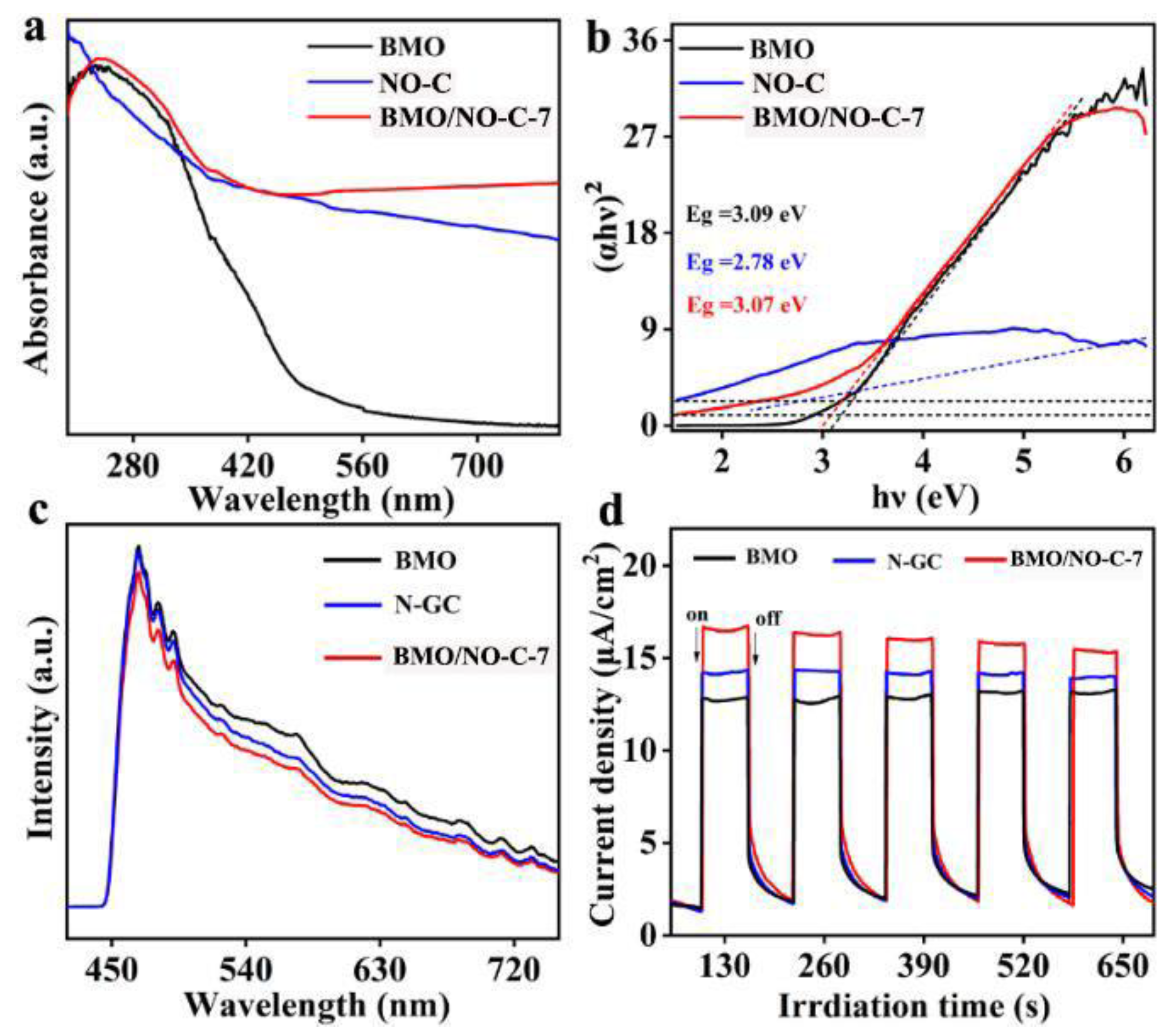
3.1. Preparation and Material Characterization

The pure ultra-thin 3D NO-C sheets were prepared by a simple polymer thermal treatment method. Scheme 1a shows that, after Cd(NO3)2·4H2O was added to the aqueous PVP solution, the Cd2+ ions can form strong interactions with the amide groups in the PVP chains, and PVP becomes a stabilizer of the dissolved Cd2+ ions. When the water in the solution is removed by drying at 95 °C, Cd2+ ions are uniformly distributed in the networks of the amide and methylene groups of the pyrrolidine ring of PVP. During the carbonization stage, PVP decomposes to form NO-C, and some CdO nanoparticles are formed. However, at a high temperature of 1000 °C, CdO is further reduced to Cd metal vapor. With the flow of N2, the Cd vapor was removed from the NO-C nanosheets. Scheme 1b shows the fabrication of BMO/NO-C composites. Bi(NO3)2·5H2O and Na2MoO4·2H2O form the Bi3+ and MoO42− ions after completely dissolved in ethylene glycol and ethanol. During the solvothermal stage, BMO nanosheets have grown on the 3D NO-C substrates to form the BMO/NO-C catalysts.
Figure S1a gives the TGA-DTG analysis of the Cd2+-PVP precursor, and the TGA curve exhibits three different stages of decomposition. The initial mass loss before 220 °C is due to the loss of the water residue (~13%). The DTG peak that occurs at 335 °C is attributed to the decomposition of the NO3 anions. The second stage of decomposition occurs between 220–440 °C and corresponds to a ~67% mass loss, indicating that most of the Cd2+-PVP precursor has been decomposed. The mild mass loss after 800 °C can be attributed to the vaporization of some Cd species.
Figure S1b shows a typical SEM image of the NO-C, which exhibits a wrinkled, fluffy, and disordered graphene-like morphology [26,27]. Figure S1c shows the X-ray diffraction (XRD) patterns of NO-C. The diffraction peaks of 22.7 and 34.2 in the XRD pattern correspond to the lattice planes (002) and (103) of graphitic carbon (JCPDS, No. 50-0926) [28]. Figure S1d presents the Raman spectrum of NO-C, which exhibits two characteristic peaks at 1340 cm−1 (D-band) and 1590 cm−1 (G-band) [29,30].
Figure 1a exhibits the XRD patterns of pure BMO and the BMO/NO-C catalysts. The strong diffraction peaks at 2θ = 28.1°, 32.2°, 46.6°, and 55.3° are attributed to the (131), (200), (062), and (331) crystal planes of Bi2MoO6 (JCPDS, No. 76-2388), respectively, and no impurity peaks detected. The FT-IR spectra in Figure 1b further confirmed that the composites were successfully prepared. The infrared peak located at 563 cm−1 corresponds to the stretching vibration of Bi–O, and a strong infrared peak located at 715 cm−1 corresponds to the asymmetric bending vibration mode of MoO6 [31]. In BMO, two vibrational peaks at 1615 cm−1 and 3415 cm−1 can be assigned to chemisorbed water molecules and O–H stretching [32,33]. The peak at 3415 cm−1, indexed to a hydroxyl group (–OH) [32], originates from the residual water in the catalysts.
Figure S2 presents the specific surface area and pore size distributions of BMO and the BMO/NO-C catalysts revealed by nitrogen adsorption–desorption isotherms, which shows that the BMO/NO-C catalysts exhibit IV-type adsorption isotherms and a type-H3 hysteresis loop. The specific surface areas (SBET) are 47.72, 50.18, 51.38, and 49.69 cm2/g for BMO, BMO/NO-C-5, BMO/NO-C-7, and BMO/NO-C-9, respectively. It is worth noting that the BMO/NO-C-7 catalyst gives the highest SBET, which can be attributed to the uniform distribution of BMO nanosheets. As more NO-C was added to the reaction system, the disordered assembly between some of the BMO nanosheets led to aggregation, which instead reduced the surface pore space and the specific surface area [33,34,35]. The inset in Figure S2 shows that the BMO/NO-C catalysts exhibit a typical mesoporous structure, which provides not only abundant channels for the diffusion of CO2 gas on the surface and inside the catalysts but also contributes many active sites for the adsorption and reduction of CO2, which is very beneficial for improving the photocatalytic CO2RR performance [36,37,38].
The microstructure and morphology of the catalysts were characterized by using SEM. The inset of Figure 2a has shown that Bi2MoO6 is spherical and composed of a large number of nanosheets. In the BMO/NO-C catalysts (Figure 2b–d), BMO nanosheets are embedded in the NO-C substrates, which is confirmed by the TEM and high-resolution TEM (HRTEM) results in Figure 3. As shown in Figure 3a, BMO nanosheets are uniformly distributed on ultra-thin N-doped graphitic carbon networks. The HRTEM in Figure 3b,c gives lattice distances of 0.32 nm of the embedded BMO, which corresponds to the (131) crystalline fringe. The HRTEM images reveal that the heterojunctions and defects are formed at the interfaces of BMO and NO-C, providing active sites for the adsorption and reduction of CO2 [39]. Atomic force microscopy (AFM) images further confirmed that the carbon nanosheets are ultrathin (Figure S4a,b). The thickness of the completely randomly measured NO-C nanosheets ranged from 1.4~2 nm (Figure S4a,b). The formation of ultra-thin, porous structures can expose abundant active sites favorable for gas diffusion on the material surface, and the use of ultrathin nanosheets can enhance the photocatalytic activity, thus reducing the charge migration distance and decreasing the recombination rate of photogenerated carriers [40].
The selected area electron diffraction (SAED) of BMO/NO-C-7 is shown in Figure 3d. The white dashed lines are the Bi2MoO6 (131), (200), and (202) crystal planes. The SAED results are consistent with the XRD ones.
X-ray photoelectron spectroscopy (XPS) was employed to determine the chemical state of the catalysts. Figure 4a displays the survey XPS spectra of NO-C, BMO, and BMO/NO-C-7. The XPS peaks for C 1s can be seen in NO-C, whereas the XPS peaks for Bi 4f, Mo 3d, and O 1s peaks are revealed in the BMO XPS spectrum. The BMO/NO-C-7 XPS exhibits the combined peaks of NO-C and BMO [41]. Figure 4b is the XPS spectra of C 1s for the pure NO-C and BMO/NO-C-7 composites. The peaks at 284.24 (284.71), 285.17 (285.61), and 288.10 (287.91) eV are identified as the sp2 C-C [7,40], C-N [42], and N-C=N [27] bonds in BMO/NO-C-7 (NO-C). The N 1s XPS spectrum of BMO/NO-C-7 (Figure 4c) shows four peaks at 398.42, 399.78, 400.82, and 405.47 eV, corresponding to the pyridinic-N [43], pyrrolic-N [44], graphitic-N [45], and oxidized-N [46], respectively. The O 1s XPS spectra (Figure 4d) exhibit three main peaks at 530.37, 531.73, and 533.43 eV, which are indexed to the lattice oxygen (O) [47], defect oxygen (O) [48,49], and chemisorbed oxygen (O) [49,50]. Figure 4e presents the Bi 4f XPS spectra of BMO/NO-C-7, and the two main peaks at 159.56 and 164.87 eV can be identified as Bi 4f7/2 and Bi 4f5/2 of Bi3+, respectively [51]. Figure 4f exhibits the Mo 3d XPS spectra, in which two major peaks at binding energies of 231.73 and 235.19 eV are indexed to Mo 3d3/2 and Mo 3d5/2 of Mo4+ [52], whereas the two remaining peaks at 232.82 and 235.97 eV arise from Mo 3d3/2 and Mo 3d5/2 of Mo6+ [53]. As compared to pure BMO, the XPS peaks for Bi and Mo in BMO/NO-C-7 all shifted to higher binding energies, indicating that some electrons transfer at the interface of BMO and NO-C.
UV–Vis diffuse spectra were employed to investigate the optical absorption properties of the catalysts. Figure 5a shows that BMO/NO-C-7 exhibits superior absorption in the UV and visible region as compared to pure BMO or NO-C, indicating higher photocatalytic activity. In addition, the band gap (Eg) of the catalysts has been calculated with the Kubelka–Munk formula: (ahν)2/n = A (hν − Eg) (α: absorption coefficient, : photon energy, A: a proportionality constant, n = 1 is for the direct band gap and n = 4 is for indirect) [54]. The calculated direct band gaps for BMO, NO-C, and BMO/NO-C-7 are 3.09, 2.78, and 3.07 eV, respectively (Figure 5b). The charge separation and transfer properties of the catalysts were further explored by using photoluminescence (PL) spectroscopy. At the excitation wavelength of 375 nm (Figure 5c), the pure BMO exhibit a strong PL intensity, and the BMO/NGC-7 catalyst gives the weakest intensity. It is well known that low PL intensity represents a high separation efficiency of the photogenerated carriers, which indicates an effective charge separation and transfer between BMO and NO-C [55]. The transient photocurrent responses of the BMO, NO-C, and BMO/NO-C-7 catalysts were recorded in Figure 5d, which shows that the photocurrent of the BMO/NO-C-7 catalyst is significantly higher than that of BMO or NO-C. BMO/NO-C-7 exhibits the highest current density, indicating a much higher separation efficiency of the light-generated charge carriers [56].
Ultraviolet photoelectron spectroscopy (UPS) was employed to measure the valence band (VB) and the conduction band (CB) of the BMO, NO-C, and BMO/NO-C composite, shown in Figure 6a. The Ecutoff energies of BMO, NO-C, and BMO/NO-C are 18.51, 18.75, and 18.62 eV, respectively (Figure 6b), while the EF-edge energies for three catalysts were 2.63, 2.04, and 2.68 eV, respectively (Figure 6c). Based on the equation EVB = −IP (ionization potential) = −(hν − (Ecutoff − EF-edge)), where is the He I photon source energy (21.21 eV), the valence band energies (EVB) of BMO, NO-C, and BMO/NO-C are −5.33, −4.50, and −5.27 eV, respectively [57,58]. According to the equation ECB = EVB + Eg (the Eg energies were taken from Figure 5), the conduction band energies (ECB) for BMO, NO-C, and BMO/NO-C are −2.24, −1.72 and −2.20 eV, respectively [59]. Significantly, the Fermi level of BMO is lower than that of NO-C, indicating that electrons are transferred from NO-C to BMO and form heterojunctions [60,61,62]. The DFT calculated work functions (Φ) of NO-C and BMO are 3.46 eV and 4.40 eV, respectively (Figure 6d,e), which is consistent with the experimental results that the EF of NO-C is higher than that of BMO. When BMO and NO-C are in contact to form a composite, electrons spontaneously transfer from NO-C to BMO until reaching equilibrium [63]. Φ of the BMO/NO-C heterojunction is 3.88 eV (Figure 6f), which is between the work functions of BMO and NO-C. In the BMO/NO-C composite, the BMO accumulates some negative charge, whereas the NO-C layer accumulates some positive charges, which is confirmed by the differential charge density analysis of DFT calculations (Figure S3d). The accumulated positive charges on NO-C and negative charges on BMO induce an internal electric field from NO-C to BMO. It is worth mentioning that the internal electric field at the interface exerts electrostatic forces on the photogenerated holes and electrons, forming a heterojunction for photocatalytic carrier separation and diffusion [64,65].

3.2. Photocatalytic CO2 Reduction

To determine the photocatalytic performance of the BMO/NO-C catalysts, we performed photocatalytic CO2 reduction experiments with the Labsolar 6A system from Beijing Perfectlight Technology Co., Ltd., (Beijing, China) which is an all-glass automatic online trace gas analysis system coupled with a 300 W Xenon lamp source (Microsolar300, Figure S4). Figure 7a shows that CH4 and CO are the main products of photocatalytic CO2 reduction, and Figure 7b compares the photocatalytic CO2 reduction performances for all catalysts. The BMO/NO-C-7 catalyst exhibited superior CH4 and CO yields of 9.14 μmol g−1 h−1 and 14.49 μmol g−1 h−1, respectively.
To further verify the photocatalytic conversion of CH4 and CO products from CO2, 13CO2, and 12CO2 gas were employed for the 13C and 12C isotopic labeling. The GC-MS results are shown in Figure 7c. The fragment peaks of 12CH4 and 13CH4 appear at m/z = 16 and m/z = 17, while the main peaks of 12CO and 13CO appear at m/z = 28 and m/z = 29, confirming that CH4 and CO come from the photocatalytic CO2RR. To test the durability and stability of the BMO/NO-C-7 catalyst, we have carried out five cycles of photocatalytic CO2RR experiments, and Figure 7d clearly shows that the BMO/NO-C-7 catalyst maintained excellent stability after five cycles. Most remarkably, the yields of CH4 and CO are very stable.

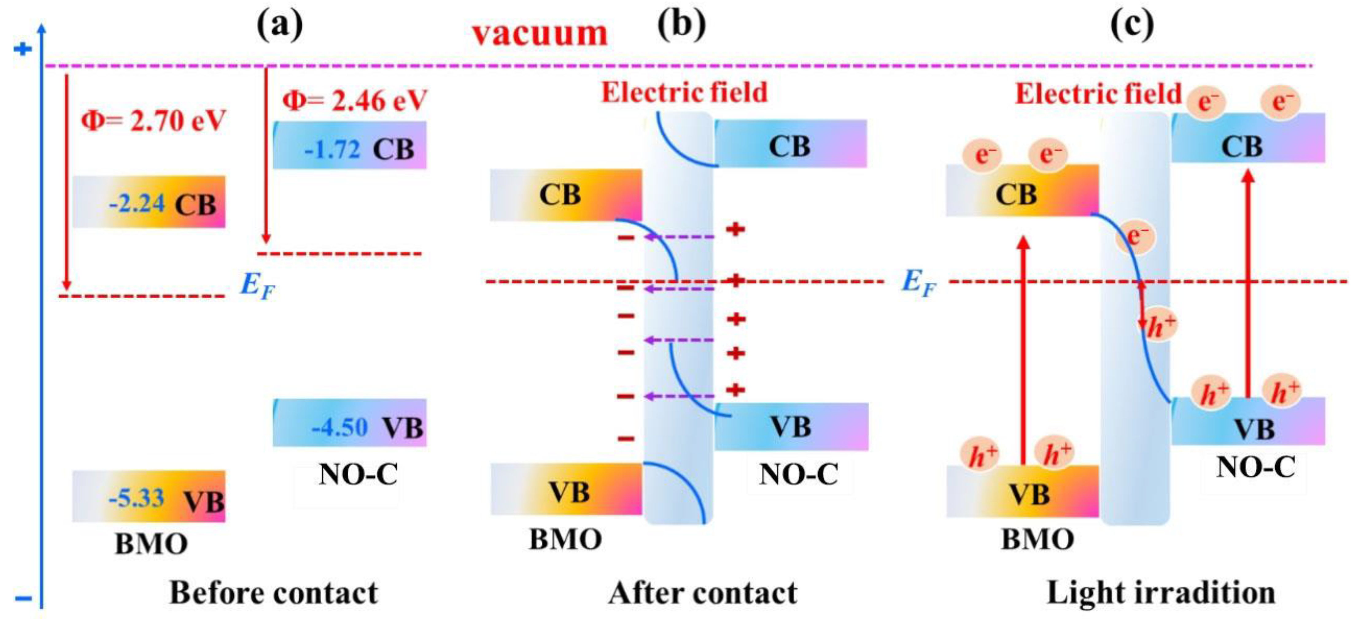
3.3. Photocatalytic CO2 Reduction Mechanism

Combining the above experimental and theoretical results, Figure 8 summarizes the photocatalytic CO2 reduction mechanism of BMO/NO-C. The overall energy band diagrams of BMO and NO-C can be plotted based on the DFT calculations and experimental data. The Φ (Figure 8a) of BMO and NO-C are 2.70 and 2.46 eV, respectively, thus the EF level of BMO is lower than that of NO-C. When BMO and NO-C are in contact to form heterostructures, electrons migrate from NO-C to BMO until the EF reaches equilibrium (Figure 8b). The energy band of BMO bends downward due to electron accumulation. The energy band of NO-C bends upward. As a result, an internal potential field is formed from NO-C to BMO. Under the irradiation of light (Figure 8c), the electrons on either BMO or NO-C catalyst VB are excited to CB.
Meanwhile, due to the strong electrostatic force from the built-in electrical field formed by electron-transfer at the BMO/NO-C interfaces, the photoexcited electrons (e) on the BMO CB migrate to the NO-C VB and combine with the holes (h+) left after photoexcitation. Therefore, the e- on the BMO CB with weak reduction ability and the h+ on the NO-C VB with weak oxidation ability are consumed. As a result, the h+ on BMO VB undergoes an oxidation reaction, and the e on the NO-C CB undergoes a reduction reaction. The step-scheme transfer mechanism promotes the carrier separation and maintains the strong redox ability, which gives BMO/NO-C a strong driving force to participate in the photocatalytic CO2 reduction reaction.

4. Conclusions

We developed a simple method to synthesize the ultrathin 3D N,O-doped carbon networks, and fabricate the BMO/NO-C catalysts by using a solvothermal method. The prepared BMO/NO-C-7 photocatalyst has good photocatalytic CO2 reduction activity, and a long-term stability of 35 h with yields of 9.14 and 14.49 μmol g−1 h−1 for CH4 and CO, respectively. This excellent performance is attributed to the fact that the three-dimensional carbon skeleton does not collapse and stack and has a large specific surface area, which allows BMO nanoparticles to be uniformly distributed in NO-C. The resulting BMO/NO-C composites further promote chemical activity due to the synergistic effect and the formation of heterogeneous structures, where the transfer of electrons and the formation of holes under light irradiation provide channels for the transfer of gas molecules. This study presents an advanced 3D photocatalyst design strategy that has the potential to open up new avenues for photocatalysis.

Supplementary Materials

The following supporting information can be downloaded at: https://www.mdpi.com/article/10.3390/nano13091569/s1, Figure S1: (a) Thermogravimetric (TG) and thermogravimetric derivative (DTG) curves for Cd2+-PVP at a heating rate of 10 °C min−1; Figure S2: N2 adsorption–desorption isotherms and pore size distributions of BMO/NO-C-5, BMO/NO-C-7, BMO/NO-C-9 and BMO; Figure S3: Models for (a) NO-C, (b) BMO (010) lattice plane and (c) Optimized BMO/NO-C structure model. (d) The differential charge density of the NO-C and BMO (010); Figure S4: (a,b) AFM image and height distribution curve of NO-C.

Author Contributions

Conceptualization: X.B., L.H. and Y.Z. (Yan Zhao); Methodology: X.B. and L.H.; Writing—original draft: X.B. and L.H.; Experiments: X.B., L.H., W.Z., F.L. and Y.Z. (Yayun Zheng); Data analysis: X.B., L.H. and X.K.; Computation: X.B.; Writing—review and editing: D.W. and Y.Z. (Yan Zhao); funding acquisition: D.W. and Y.Z. (Yan Zhao). All authors have read and agreed to the published version of the manuscript.

Funding

This research received no external funding.

Data Availability Statement

Not applicable.

Acknowledgments

We are grateful to Wuhan University for its financial support and computational resources. This work is partly supported by the Key R&D Program of Hubei (2021BAA173). Many thanks to Siwei Zhu from Chengdu Jinjiang Jiaxiang Foreign Languages Senior High School for the full grammatical revision.

Conflicts of Interest

The authors declare no conflict of interest.

References

  1. Xia, Y.; Zhang, L.; Hu, B.; Yu, J.; Al-Ghamdi, A.A.; Wageh, S. Design of highly-active photocatalytic materials for solar fuel production. Chem. Eng. J. 2021, 421, 127732. [Google Scholar] [CrossRef]
  2. Guo, K.; Hussain, I.; Jie, G.A.; Fu, Y.; Zhang, F.; Zhu, W. Strategies for improving the photocatalytic performance of metal-organic frameworks for CO2 reduction: A review. J. Environ. Sci. 2023, 125, 290–308. [Google Scholar] [CrossRef] [PubMed]
  3. Dong, X.-Y.; Si, Y.-N.; Wang, Q.-Y.; Wang, S.; Zang, S.-Q. Integrating Single Atoms with Different Microenvironments into One Porous Organic Polymer for Efficient Photocatalytic CO2 Reduction. Adv. Mater. 2021, 33, 2101568. [Google Scholar] [CrossRef] [PubMed]
  4. Park, Y.H.; Kim, D.; Hiragond, C.B.; Lee, J.; Jung, J.-W.; Cho, C.-H.; In, I.; In, S.-I. Phase-controlled 1T/2H-MoS2 interaction with reduced TiO2 for highly stable photocatalytic CO2 reduction into CO. J. CO2 Util. 2023, 67, 102324. [Google Scholar] [CrossRef]
  5. Chauhan, D.K.; Sharma, N.; Kailasam, K. A critical review on emerging photocatalysts for syngas generation via CO2 reduction under aqueous media: A sustainable paradigm. Mater. Adv. 2022, 3, 5274–5298. [Google Scholar] [CrossRef]
  6. Feng, Y.-X.; Dong, G.-X.; Su, K.; Liu, Z.-L.; Zhang, W.; Zhang, M.; Lu, T.-B. Self-template-oriented synthesis of lead-free perovskite Cs3Bi2I9 nanosheets for boosting photocatalysis of CO2 reduction over Z-scheme heterojunction Cs3Bi2I9/CeO2. J. Energy Chem. 2022, 69, 348–355. [Google Scholar] [CrossRef]
  7. Tang, Z.; He, W.; Wang, Y.; Wei, Y.; Yu, X.; Xiong, J.; Wang, X.; Zhang, X.; Zhao, Z.; Liu, J. Ternary heterojunction in rGO-coated Ag/Cu2O catalysts for boosting selective photocatalytic CO2 reduction into CH4. Appl. Catal. B Environ. 2022, 311, 121371. [Google Scholar] [CrossRef]
  8. Wan, Z.; Wang, J.; Wang, K.; Hu, M.; Wang, X. Photocatalytic reduction of CO2 with H2O vapor into solar fuels over Ni modified porous In2O3 nanosheets. Catal. Today 2021, 374, 44–52. [Google Scholar] [CrossRef]
  9. Skorjanc, T.; Kamal, K.M.; Alkhoori, A.; Mali, G.; Mohammed, A.K.; Asfari, Z.; Polychronopoulou, K.; Likozar, B.; Trabolsi, A.; Shetty, D. Polythiacalixarene-Embedded Gold Nanoparticles for Visible-Light-Driven Photocatalytic CO2 Reduction. ACS Appl. Mater. Interfaces 2022, 14, 30796–30801. [Google Scholar] [CrossRef]
  10. Phuong, P.T.T.; Vo, D.-V.N.; Duy, N.P.H.; Pearce, H.; Tsikriteas, Z.M.; Roake, E.; Bowen, C.; Khanbareh, H. Piezoelectric catalysis for efficient reduction of CO2 using lead-free ferroelectric particulates. Nano Energy 2022, 95, 107032. [Google Scholar] [CrossRef]
  11. Meng, J.; Duan, Y.; Jing, S.; Ma, J.; Wang, K.; Zhou, K.; Ban, C.; Wang, Y.; Hu, B.; Yu, D.; et al. Facet junction of BiOBr nanosheets boosting spatial charge separation for CO2 photoreduction. Nano Energy 2022, 92, 106671. [Google Scholar] [CrossRef]
  12. Xue, M.L.; Meng, F.M.; Ma, Y.R.; Zhou, S.W. Growing of ultra-thin Bi2MoO6 nanoflowers on Co/N-doped graphitic carbon nanoshells as attractive custom supports: Excellent photocatalytic degradation activity for pollutants. Appl. Surf. Sci. 2023, 613, 156100. [Google Scholar] [CrossRef]
  13. Liu, L.L.; Wu, D.H.; Zhang, L.; Feng, J.J.; Wang, A.J. FeCo alloy entrapped in N-doped graphitic carbon nanotubes-onnanosheets prepared by coordination-induced pyrolysis for oxygen reduction reaction and rechargeable Zn-air battery. J. Colloid Interface Sci. 2023, 639, 424–433. [Google Scholar] [CrossRef] [PubMed]
  14. Feng, X.; Bai, Y.; Liu, M.; Li, Y.; Yang, H.; Wang, X.; Wu, C. Untangling the respective effects of heteroatom-doped carbon materials in batteries, supercapacitors and the ORR to design high performance materials. Energy Environ. Sci. 2021, 14, 2036–2089. [Google Scholar] [CrossRef]
  15. Liu, M.; Lu, X.Q.; Guo, C.; Wang, Z.J.; Li, Y.P.; Lin, Y.; Zhou, Y.; Wang, S.T.; Zhang, J. Architecting a Mesoporous N-Doped Graphitic Carbon Framework Encapsulating CoTe2 as an Efficient Oxygen Evolution Electrocatalyst. ACS Appl. Mater. Interfaces 2017, 9, 36146–36153. [Google Scholar] [CrossRef]
  16. Wang, B.L.; Shi, F.; Sun, Y.X.; Yan, L.J.; Zhang, X.P.; Wang, B.; Sun, W. Ni-enhanced molybdenum carbide loaded N-doped graphitized carbon as bifunctional electrocatalyst for overall water splitting. Appl. Surf. Sci. 2022, 572, 151480. [Google Scholar] [CrossRef]
  17. Wang, B.; Gu, L.; Yuan, F.; Zhang, D.; Sun, H.L.; Wang, J.; Wang, Q.J.; Wang, H.; Li, Z.J. Edge-enrich N-doped graphitic carbon: Boosting rate capability and cyclability for potassium ion battery. Chem. Eng. J. 2022, 432, 134321. [Google Scholar] [CrossRef]
  18. Filippi, J.; Miller, H.A.; Nasi, L.; Pagliaro, M.V.; Marchionni, A.; Melchionna, M.; Fornasiero, P.; Vizza, F. Optimization of H2O2 production in a small-scale off-grid buffer layer flow cell equipped with Cobalt@N-doped graphitic carbon core–shell nanohybrid electrocatalyst. Mater. Today Energy 2022, 29, 101092. [Google Scholar] [CrossRef]
  19. Liu, D.; Jiang, Z.; Lin, Y.; Zheng, J. S-Scheme Photocatalytic Mechanism of Type-I Band Alignment in α-In2Se3/g-C3N4 Heterostructure. Phys. Status Solidi RRL 2021, 15, 2100241. [Google Scholar] [CrossRef]
  20. Georgieva, A.K.; Nilsson, D.; Stattin, M.; Forsberg, U.; Haglund, A.; Larsson, A.; Janzén, E. Mg-doped Al0.85Ga0.15N layers grown by hot-wall MOCVD with low resistivity at room temperature. Phys. Stat. Sol. 2010, 4, 311–313. [Google Scholar]
  21. Lundgren, C.; Georgieva, A.K.; Gueorguiev, G.K. A perspective on thermal stability and mechanical properties of 2D Indium Bismide from ab initio molecular dynamics. Nanotechnology 2022, 33, 335706. [Google Scholar] [CrossRef] [PubMed]
  22. Zhang, G.; Chen, D.; Li, N.; Xu, Q.; Li, H.; He, J.; Lu, J. Fabrication of Bi2MoO6/ZnO hierarchical heterostructures with enhanced visible-light photocatalytic activity. Appl. Catal. B Environ. 2019, 250, 313–324. [Google Scholar] [CrossRef]
  23. He, L.; Zhang, W.Y.; Liu, S.; Zhao, Y. Three-dimensional porous N-doped graphitic carbon framework with embedded CoO for photocatalytic CO2 reduction. Appl. Catal. B-Environ. 2021, 298, 120546. [Google Scholar] [CrossRef]
  24. He, L.; Zhang, W.; Zhao, K.; Liu, S.; Zhao, Y. Core-shell Cu@Cu2O nanoparticles embedded in 3D honeycomb-like N-doped graphitic carbon for photocatalytic CO2 reduction. J. Mater. Chem. A 2022, 10, 4758–4769. [Google Scholar] [CrossRef]
  25. He, L.; Lv, H.; Ma, L.; Li, W.; Si, J.; Ikram, M.; Ullah, M.; Wu, H.; Wang, R.; Shi, K. Controllable synthesis of intercalated γ-Bi2MoO6/graphene nanosheet composites for high performance NO2 gas sensor at room temperature. Carbon 2020, 157, 22–32. [Google Scholar] [CrossRef]
  26. Al-Hada, N.M.; Saion, E.; Kamari, H.M.; Flaifel, M.H.; Shaari, A.H.; Talib, Z.A.; Abdullahi, N.; Baqer, A.A.; Kharazmi, A. Structural, morphological and optical behaviour of PVP capped binary (ZnO)(0.4) (CdO)(0.6) nanoparticles synthesised by a facile thermal route. Mater. Sci. Semicond. Process. 2016, 53, 56–65. [Google Scholar] [CrossRef]
  27. Anju; Yadav, R.S.; Pötschke, P.; Pionteck, J.; Krause, B.; Kuřitka, I.; Vilcakova, J.; Skoda, D.; Urbánek, P.; Machovsky, M.; et al. High-Performance, Lightweight, and Flexible Thermoplastic Polyurethane Nanocomposites with Zn2+-Substituted CoFe2O4 Nanoparticles and Reduced Graphene Oxide as Shielding Materials against Electromagnetic Pollution. ACS Omega 2021, 6, 28098–28118. [Google Scholar] [CrossRef]
  28. Zheng, Y.Y.; He, L.; Kong, X.R.; Song, Y.; Zhao, Y. Three-dimensional porous N-doped graphite carbon with embedded CoS2 nanoparticles as advanced anode for sodium-ion batteries. Appl. Surf. Sci. 2022, 603, 154481. [Google Scholar] [CrossRef]
  29. Wang, Y.; Di, X.; Lu, Z.; Cheng, R.; Wu, X.; Gao, P. Controllable heterogeneous interfaces of cobalt/carbon nanosheets/rGO composite derived from metal-organic frameworks for high-efficiency microwave attenuation. Carbon 2022, 187, 404–414. [Google Scholar] [CrossRef]
  30. Sharma, M.; Rani, S.; Pathak, D.K.; Bhatia, R.; Kumar, R.; Sameera, I. Temperature dependent Raman modes of reduced graphene oxide: Effect of anharmonicity, crystallite size and defects. Carbon 2021, 184, 437–444. [Google Scholar] [CrossRef]
  31. Zheng, Z.; Li, H.; Zhang, X.; Jiang, H.; Geng, X.; Li, S.; Tu, H.; Cheng, X.; Yang, P.; Wan, Y. High-absorption solar steam device comprising Au@Bi2MoO6-CDs: Extraordinary desalination and electricity generation. Nano Energy 2020, 68, 104298. [Google Scholar] [CrossRef]
  32. Chen, S.; Feng, W.J.; Geng, Q.; Dong, F.; Wang, H.Q.; Wu, Z.B. A new strategy for plasma-catalytic reduction of NO to N2 on the surface of modified Bi2MoO6. Chem. Eng. J. 2022, 440, 135754. [Google Scholar] [CrossRef]
  33. Liu, Z.P.; Tai, Y.H.; Liu, J.M.; Liu, F.Y.; Han, B.Y.; Fu, W.; Yang, X.Y.; Xie, H.J.; Liu, Q.F. A novel mechanism for visible-light degradation of phenol by oxygen vacancy Bi2MoO6 homojunction. Appl. Surf. Sci. 2022, 605, 154671. [Google Scholar] [CrossRef]
  34. Bai, X.; Liu, Z.; Lv, H.; Chen, J.; Khan, M.; Wang, J.; Sun, B.; Zhang, Y.; Kan, K.; Shi, K. N-doped three-dimensional needle-like CoS2 bridge connection Co3O4 core–shell structure as high-efficiency room temperature NO2 gas sensor. J. Hazard. Mater. 2022, 423, 127120. [Google Scholar] [CrossRef]
  35. Yu, T.; Li, Z.; Chen, S.; Ding, Y.; Chen, W.; Liu, X.; Huang, Y.; Kong, F. Facile Synthesis of Flowerlike Bi2MoO6 Hollow Microspheres for High-Performance Supercapacitors. ACS Sustain. Chem. Eng. 2018, 6, 7355–7361. [Google Scholar] [CrossRef]
  36. He, L.; Zhang, W.; Lv, F.; Kong, X.; Zheng, Y.; Song, Y.; Zhao, Y. CoFe alloy nanoparticles encapsulated in a 3D honeycomb-like N-doped graphitic carbon framework for photocatalytic CO2 reduction. J. Mater. Chem. A 2022, 10, 22093–22104. [Google Scholar] [CrossRef]
  37. Wang, B.L.; Ai, Y.J.; Yao, Y.C.; Jiang, M.; Yan, L.J.; Xu, S.G.; Sun, W. Electrochemical synergy between FeNi nanoalloy@tungsten carbide on N-doped graphitized carbon layers as an excellent electrocatalyst for oxygen evolution reaction. Electrochim. Acta 2022, 415, 140254. [Google Scholar] [CrossRef]
  38. Suzuki, T.M.; Yoshino, S.; Sekizawa, K.; Yamaguchi, Y.; Kudo, A.; Morikawa, T. Photocatalytic CO2 reduction by a Z-scheme mechanism in an aqueous suspension of particulate (CuGa)0.3Zn1.4S2, BiVO4 and a Co complex operating dual-functionally as an electron mediator and as a cocatalyst. Appl. Catal. B Environ. 2022, 316, 121600. [Google Scholar] [CrossRef]
  39. Wang, Z.; Fan, J.; Cheng, B.; Yu, J.; Xu, J. Nickel-based cocatalysts for photocatalysis: Hydrogen evolution, overall water splitting and CO2 reduction. Mater. Today Phys. 2020, 15, 100279. [Google Scholar] [CrossRef]
  40. Gao, W.H.; Li, G.; Wang, Q.W.; Zhang, L.J.; Wang, K.; Pang, S.X.; Zhang, G.M.; Lv, L.Y.; Liu, X.Y.; Gao, W.F.; et al. Ultrathin porous Bi2WO6 with rich oxygen vacancies for promoted adsorption-photocatalytic tetracycline degradation. Chem. Eng. J. 2023, 464, 142694. [Google Scholar] [CrossRef]
  41. Cai, W.; Yu, X.; Cao, Y.; Hu, C.; Wang, Y.; Zhao, Y.; Bu, Y. Electron-coupled enhanced interfacial interaction of Ce-MOF/Bi2MoO6 heterostructure for boosted photoreduction CO2. J. Environ. Chem. Eng. 2022, 10, 107461. [Google Scholar] [CrossRef]
  42. Li, B.; Lai, C.; Zhang, M.; Liu, S.; Yi, H.; Liu, X.; An, N.; Zhou, X.; Li, L.; Fu, Y.; et al. N, S-GQDs and Au nanoparticles co-modified ultrathin Bi2MoO6 nanosheet with enhanced charge transport dynamics for full-spectrum-light-driven molecular oxygen activation. Chem. Eng. J. 2021, 409, 128281. [Google Scholar] [CrossRef]
  43. Xue, Y.; Tang, W.; Gu, H.; Wei, M.; Guo, E.; Lu, Q.; Pang, Y. Flexible Bi2MoO6/N-doped carbon nanofiber membrane enables tetracycline photocatalysis for environmentally safe growth of Vigna radiata. J. Alloys Compd. 2022, 902, 163860. [Google Scholar] [CrossRef]
  44. Li, P.; Wang, H.L.; Tan, X.H.; Hu, W.; Huang, M.H.; Shi, J.; Chen, J.W.; Liu, S.; Shi, Z.C.; Li, Z. Bifunctional electrocatalyst with CoN3 active sties dispersed on N-doped graphitic carbon nanosheets for ultrastable Zn-air batteries. Appl. Catal. B Environ. 2022, 316, 121674. [Google Scholar] [CrossRef]
  45. Alhokbany, N.; Ahamad, T.; Alshehri, S.M. Fabrication of highly porous ZnO/Ag2O nanoparticles embedded in N-doped graphitic carbon for photocatalytic degradation of tetracycline. J. Environ. Chem. Eng. 2022, 10, 107681. [Google Scholar] [CrossRef]
  46. Wang, G.; Sun, X.; Bai, J.; Han, L. Preparation of Fe-C nanofiber composites by metal organic complex and potential application in supercapacitors. J. Mater. Sci. Mater. Electron. 2019, 30, 4665–4675. [Google Scholar] [CrossRef]
  47. Ikram, M.; Liu, Y.; Lv, H.; Liu, L.; Rehman, A.U.; Kan, K.; Zhang, W.; He, L.; Wang, Y.; Wang, R.; et al. 3D-multilayer MoS2 nanosheets vertically grown on highly mesoporous cubic In2O3 for high-performance gas sensing at room temperature. Appl. Surf. Sci. 2019, 466, 1–11. [Google Scholar] [CrossRef]
  48. Liu, Y.; Wang, Y.; Ikram, M.; Lv, H.; Chang, J.; Li, Z.; Ma, L.; Rehman, A.; Lu, G.; Chen, J. Facile Synthesis of Highly Dispersed Co3O4 Nanoparticles on Expanded, Thin Black Phosphorus for a ppb-Level NOx Gas Sensor. ACS Sens. 2018, 3, 1576–1583. [Google Scholar] [CrossRef]
  49. Chen, H.; You, S.; Ma, Y.; Zhang, C.; Jing, B.; Cai, Z.; Tang, B.; Ren, N.; Zou, J. Carbon Thin-Layer-Protected Active Sites for ZIF-8-Derived Nitrogen-Enriched Carbon Frameworks/Expanded Graphite as Metal-Free Catalysts for Oxygen Reduction in Acidic Media. Chem. Mater. 2018, 30, 6014–6025. [Google Scholar] [CrossRef]
  50. He, L.; Zhang, W.; Liu, S.; Zhao, Y. Three-dimensional palm frondlike Co3O4@NiO/graphitic carbon composite for photocatalytic CO2 reduction. J. Alloys Compd. 2023, 934, 168053. [Google Scholar] [CrossRef]
  51. Yu, B.; Wu, Y.; Meng, F.; Wang, Q.; Jia, X.; Khan, M.W.; Huang, C.; Zhang, S.; Yang, L.; Wu, H. Formation of hierarchical Bi2MoO6/ln2S3 S-scheme heterojunction with rich oxygen vacancies for boosting photocatalytic CO2 reduction. Chem. Eng. J. 2022, 429, 132456. [Google Scholar] [CrossRef]
  52. Ko, D.; Jin, X.; Seong, K.-D.; Yan, B.; Chai, H.; Kim, J.M.; Hwang, M.; Choi, J.; Zhang, W.; Piao, Y. Few-layered MoS2 vertically aligned on 3D interconnected porous carbon nanosheets for hydrogen evolution. Appl. Catal. B Environ. 2019, 248, 357–365. [Google Scholar] [CrossRef]
  53. Li, H.; Jian, L.; Chen, Y.; Wang, G.; Lyu, J.; Dong, X.; Liu, X.; Ma, H. Fabricating Bi2MoO6@Co3O4 core–shell heterogeneous architectures with Z-scheme for superior photoelectrocatalytic water purification. Chem. Eng. J. 2022, 27, 131716. [Google Scholar] [CrossRef]
  54. Huo, Y.; Zhang, J.; Dai, K.; Liang, C. Amine-Modified S-Scheme Porous g-C3N4/CdSe–Diethylenetriamine Composite with Enhanced Photocatalytic CO2 Reduction Activity. ACS Appl. Energy Mater. 2021, 4, 956–968. [Google Scholar] [CrossRef]
  55. Xu, D.; Cheng, B.; Wang, W.; Jiang, C.; Yu, J. Ag2CrO4/g-C3N4/graphene oxide ternary nanocomposite Z-scheme photocatalyst with enhanced CO2 reduction activity. Appl. Catal. B Environ. 2018, 231, 368–380. [Google Scholar] [CrossRef]
  56. Di, T.; Zhu, B.; Cheng, B.; Yu, J.; Xu, J. A direct Z-scheme g-C3N4/SnS2 photocatalyst with superior visible-light CO2 reduction performance. J. Catal. 2017, 352, 532–541. [Google Scholar] [CrossRef]
  57. Liu, J.; Liu, Y.; Liu, N.Y.; Han, Y.Z.; Zhang, X.; Huang, H.; Lifshitz, Y.; Lee, S.T.; Zhong, J.; Kang, Z.H. Metal-free efficient photocatalyst for stable visible water splitting via a two-electron pathway. Science 2015, 347, 970–974. [Google Scholar] [CrossRef]
  58. Teng, Y.L.; Xu, Y.M.; Cheng, X.L.; Gao, S.; Zhang, X.F.; Zhao, H.; Huo, L.H. Lonicerae flos-derived N, S co-doped graphitized carbon uniformly embedded with FeS2 nanoparticles as anode materials for high performance lithium ion batteries. J. Alloys Compd. 2022, 909, 164707. [Google Scholar] [CrossRef]
  59. Liu, M.X.; Zhang, J.J.; Cui, F.; Yan, Y.Q.; Cui, T.Y. Synergized Ni/NiOx heterojunction encapsulated by N-doped graphitized carbon core@shell electrocatalyst for efficient hydrogen production. Mater. Lett. 2022, 327, 133043. [Google Scholar] [CrossRef]
  60. Ma, C.; Xie, Z.; Seo, W.C.; Din, S.T.U.; Lee, J.; Kim, Y.; Jung, H.; Yang, W. Carbon dot-coupled BiVO4/reduced graphene hydrogel for significant enhancement of photocatalytic activity: Antibiotic degradation and CO2 reduction. Appl. Surf. Sci. 2021, 565, 150564. [Google Scholar] [CrossRef]
  61. Zhou, Y.; Jiao, W.; Xie, Y.; He, F.; Ling, Y.; Yang, Q.; Zhao, J.; Ye, H.; Hou, Y. Enhanced photocatalytic CO2-reduction activity to form CO and CH4 on S-scheme heterostructured ZnFe2O4/Bi2MoO6 photocatalyst. J. Colloid Interface Sci. 2022, 608, 2213–2223. [Google Scholar] [CrossRef] [PubMed]
  62. Liu, H.; Yang, D.H.; Wang, X.Y.; Zhang, J.W.; Han, B.H. N-doped graphitic carbon shell-encapsulated FeCo alloy derived from metal–polyphenol network and melamine sponge for oxygen reduction, oxygen evolution, and hydrogen evolution reactions in alkaline media. J. Colloid Interface Sci. 2021, 581, 362–373. [Google Scholar] [CrossRef] [PubMed]
  63. Sun, X.P.; Qi, H.Q.; Mao, S.Q.; Sun, Z.R. Atrazine removal by peroxymonosulfate activated with magnetic CoFe alloy@N-doped graphitic carbon encapsulated in chitosan carbonized microspheres. Chem. Eng. J. 2021, 423, 130169. [Google Scholar] [CrossRef]
  64. Yu, Y.; You, S.J.; Du, J.N.; Zhang, P.; Dai, Y.; Liu, M.Y.; Jiang, B.J.; Ren, N.Q.; Zou, J.L. Ti3+-self-doped TiO2 with multiple crystal-phases anchored on acid-pickled ZIF-67-derived Co3O4@N-doped graphitized-carbon as a durable catalyst for oxygen reduction in alkaline and acid media. Chem. Eng. J. 2021, 403, 126441. [Google Scholar] [CrossRef]
  65. Yin, G.; Qi, X.; Chen, Y.; Peng, Q.; Jiang, X.; Wang, Q.; Zhang, W.; Gong, X. Constructing an all zero-dimensional CsPbBr3/CdSe heterojunction for highly efficient photocatalytic CO2 reduction. J. Mater. Chem. A 2022, 10, 22468–22476. [Google Scholar] [CrossRef]
Scheme 1. Schematic illustration of the formation of nanocomposite, (a) NO-C; (b) BMO/NO-C.
Nanomaterials 13 01569 sch001
Figure 1. (a) XRD diffraction patterns of BMO/NO-C-5, BMO/NO-C-7, BMO/NO-C-9, and BMO (The standard JCPDS cards of Bi2MoO6 are shown under the XRD pattern). (b) FT-IR of BMO/NO-C-5, BMO/NO-C-7, BMO/NO-C-9, NO-C, and BMO.
Nanomaterials 13 01569 g001
Figure 2. SEM images of BMO (a), BMO/NO-C-5 (b), BMO/NO-C-7 (c), and BMO/NO-C-9 (d).
Nanomaterials 13 01569 g002
Figure 3. (a) TEM images of BMO/NO-C-7, (b) and (c) HRTEM images of BMO/NO-C-7, (d) SAED pattern of BMO/NO-C-7.
Nanomaterials 13 01569 g003
Figure 4. (a) XPS survey spectra of BMO, NO-C, and BMO/NO-C-7. High-resolution XPS spectra of (b) C 1s, (c) N 1s, (d) O 1s (e) Bi 4f, and (f) Mo 3d of the BMO and BMO/NO-C-7.
Nanomaterials 13 01569 g004
Figure 5. BMO/NO-C-7, NO-C, and BMO of (a) UV–vis diffuse reflectance spectra, and (b) Plots of (ahν)2 versus energy (). (c) PL spectra of the BMO, NO-C, and BNO/NO-C. (d) transient photocurrent response of BMO, NO-C, and BMO/NO-C-7.
Nanomaterials 13 01569 g005
Figure 6. (a) UPS spectra of the BMO, NO-C, and BMO/NO-C films, (b) cutoff energy (the dashed lines mark the baseline and the tangents of the curve) and (c) the intersections of the tangents with the baseline give the fermi (EF) edges. Calculated electrostatic potentials (Φ) of (d) NO-C and (e) Bi2MoO6. (f) BMO/NO-C heterojunction slab model. The Fermi level is marked with a dashed red line, and the vacuum level is marked with a dashed blue line.
Nanomaterials 13 01569 g006
Figure 7. (a) The CO2 reduction spectrum of all composites accumulated for 1 h of light irradiation. (b) Photocatalytic activity of different samples for CO2 reduction (A: BMO, B: NO-C, C: BMO/NO-C-5, D: BMO/NO-C-7, E: BMO/NO-C-9). (c) The GC-MS patterns of the produced CH4 and CO over BMO/NO-C-7 using 12CO2 and 13CO2 as the carbon source, respectively. (d) The photocatalytic cycle performance of BMO/NO-C-7.
Nanomaterials 13 01569 g007
Figure 8. Diagram of the band edge positions before (a) and after contact (b) of BMO and NO-C. (c) The step-scheme electrons transfer diagram between BMO and NO-C under the full spectrum.
Nanomaterials 13 01569 g008
Disclaimer/Publisher’s Note: The statements, opinions and data contained in all publications are solely those of the individual author(s) and contributor(s) and not of MDPI and/or the editor(s). MDPI and/or the editor(s) disclaim responsibility for any injury to people or property resulting from any ideas, methods, instructions or products referred to in the content.

