Article

Low-Temperature Enhancement-Mode Amorphous Oxide Thin-Film Transistors in Solution Process Using a Low-Pressure Annealing

School of Electronic and Electrical Engineering, Kyungpook National University, Daegu 41566, Republic of Korea
*
Authors to whom correspondence should be addressed.
Current address: LG Display, Paju 10845, Republic of Korea.
Nanomaterials 2023, 13(15), 2231; https://doi.org/10.3390/nano13152231
Submission received: 29 June 2023 / Revised: 28 July 2023 / Accepted: 31 July 2023 / Published: 1 August 2023

Abstract

:
The interest in low processing temperature for printable transistors is rapidly increasing with the introduction of a new form factor in electronics and the growing importance of high throughput. This paper reports the fabrication of low-temperature-processable enhancement-mode amorphous oxide thin-film transistors (TFTs) using the solution process. A facile low-pressure annealing (LPA) method is proposed for the activation of indium oxide (InOx) semiconductors at a significantly low processing temperature of 200 °C. Thermal annealing at a pressure of about ~10 Torr induces effective condensation in InOx even at a low temperature. As a result, the fabricated LPA InOx TFTs not only functioned in enhancement mode but also exhibited outstanding switching characteristics with a high on/off current ratio of 4.91 × 10⁹. Furthermore, the LPA InOx TFTs exhibit stable operation under bias stress compared to the control device due to the low concentration of hydroxyl defects.

1. Introduction

Oxide thin-film transistors (TFTs) are regarded as one of the most important building blocks for applications such as displays, optoelectronics, and back-end-of-line transistors [1,2,3,4]. Recently, the solution process for oxide TFTs has attracted a lot of attention because it enables large-area manufacturing and high throughput [5,6,7]. However, compared to conventional sputtering-based oxide TFTs, solution-processed oxide TFTs not only exhibit relatively low field effect mobility (μFE) and electrical stability but also require a high processing temperature (>400 °C) [8]. In particular, high processing temperature leads to limitations in the application of flexible polymer substrates, making it difficult to utilize in next-generation electronics with new form factors [6]. Unfortunately, the solution-processed oxide TFTs fabricated at a low temperature of 200–300 °C exhibit extremely low μFE and electrical stabilities.
Binary oxides, such as tin oxide and indium oxide (InOx), were studied to address these issues [9,10]. Although these semiconducting materials can be used to obtain high mobility, a high electron concentration of these materials cause the negative threshold voltage (VT), thereby resulting in depletion-mode TFTs. However, the positive VT is suitable for the pixel and gate driver circuits because enhancement-mode characteristic simplifies the circuit design and reduces power consumption [11,12]. Moreover, binary oxides typically have poly- or nanocrystalline structures [9,13,14]. Fabricating enhancement-mode oxide TFTs through low processing temperatures in the solution process is urgently required.
This work seeks to address the aforementioned issues by reporting the fabrication of enhancement-mode amorphous oxide TFTs at a low processing temperature of 200 °C using a solution process. A low-pressure annealing (LPA) method is introduced to achieve the activation and densification of solution-processed InOx semiconductors at a significantly lower processing temperature of 200 °C. Thermal annealing at a low pressure of about ~10 Torr helps in diffusing out hydrogen even at low temperatures, resulting in an effective condensation reaction. Considering that the vacuum of thermal evaporation used for organic light-emitting diode deposition has a pressure of ~10−6 Torr, an efficient semiconductor activation can be achieved with a relatively weak vacuum level. As a result, the LPA InOx TFTs not only functioned in the enhancement mode but also exhibited excellent switching characteristics with a high on/off current ratio of 4.9 × 10⁹. Furthermore, compared with the control devices, the LPA InOx TFTs exhibited stable operation under positive and negative gate bias stress compared with the control devices.

2. Materials and Methods

A 0.1 M InOx solution was prepared by dissolving In(NO3)3⋅xH2O (Sigma-Aldrich, St. Louis, MO, USA) in 2-methoxyethanol to fabricate InOx semiconductor thin films. The solution was stirred at 50 °C for 3 h to obtain a clear and homogeneous solution. A 100 nm thick Si/SiO2 wafer substrate was prepared for the gate electrode and dielectric through cleaning with sonication in acetone, isopropyl alcohol, and deionized (DI water) for 10 min each. The residual moisture present on the wafers was fully removed by N2 and annealed at 350 °C. Figure 1 shows a schematic of the fabrication process of oxide TFTs. For the patterning of InOx semiconductors on SiO2 dielectric, the water etchant-based photopatterning method was used, which was reported previously [15]. First, a 0.1 M InOx solution was spin-coated on the SiO2 dielectric at 3000 rpm for 20 s to create a film thickness of 7 nm. The precursor solution-deposited substrate was soft-baked at 100 °C for 1 min. Afterward, to avoid ozone generation, the sample covered with a fine metal mask was exposed to ultraviolet (UV) radiation (25 mW cm−2) from a low-pressure mercury lamp with two main wavelengths of 253.7 nm (90%) and 184.9 nm (10%) in N2 ambient for 150 s. In this stage, the photochemical cleavage of alkoxy groups and the decomposition of nitrate ligands were achieved in InOx [15,16]. Consecutively, the substrate was developed in DI water etchant for 1 min. Etching through water supplies additional water molecules to InOx and promotes the condensation reaction in the subsequent annealing process [15,17]. Pre-annealing was conducted at 100 °C in atmospheric conditions for 10 min. To fabricate the control device, which was annealed in an NPA (normal pressure annealing) environment, it was post-annealed in an oven at 200 °C for 2 h without vacuum (760 Torr). To fabricate the low-pressure annealed InOx based TFTs, InOx was post-annealed in an oven at a low-pressure environment of 10 Torr for 2 h at 200 °C. The InOx films annealed under normal- and low-pressure are called NPA and LPA InOx. Finally, the 50 nm-thick Al was deposited using thermal evaporation for source and drain electrodes. The channel length (L) and width (W) were 100 and 1000 μm, respectively. X-ray photoelectron spectroscopy (XPS) (NEXSA, Thermo Fisher Scientific, Waltham, MA, USA) was used to analyze the chemical composition of the NPA and LPA InOx thin films. Grazing incidence X-ray diffraction (GIXRD) (DMAX-2500-PC, Rigaku, Tokyo, Japan) was performed to characterize the crystal structure of InOx. X-ray reflectance (XRR) (ATX-G, Rigaku) measurements were performed to investigate the film density of NPA and LPA InOx. The dielectric properties of NPA InOx and LPA InOx were analyzed using a probe station (Model 4000, MS Tech, Arlington, VA, USA) equipped with a precision LCR meter (Keysight, Santa Rosa, CA, USA) and a semiconductor parameter analyzer (Keithley 2636 B, Tektronix Inc., Beaverton, OR, USA).

3. Results and Discussion

3.1. Effect of LPA on Atomic Bonding State of InOx

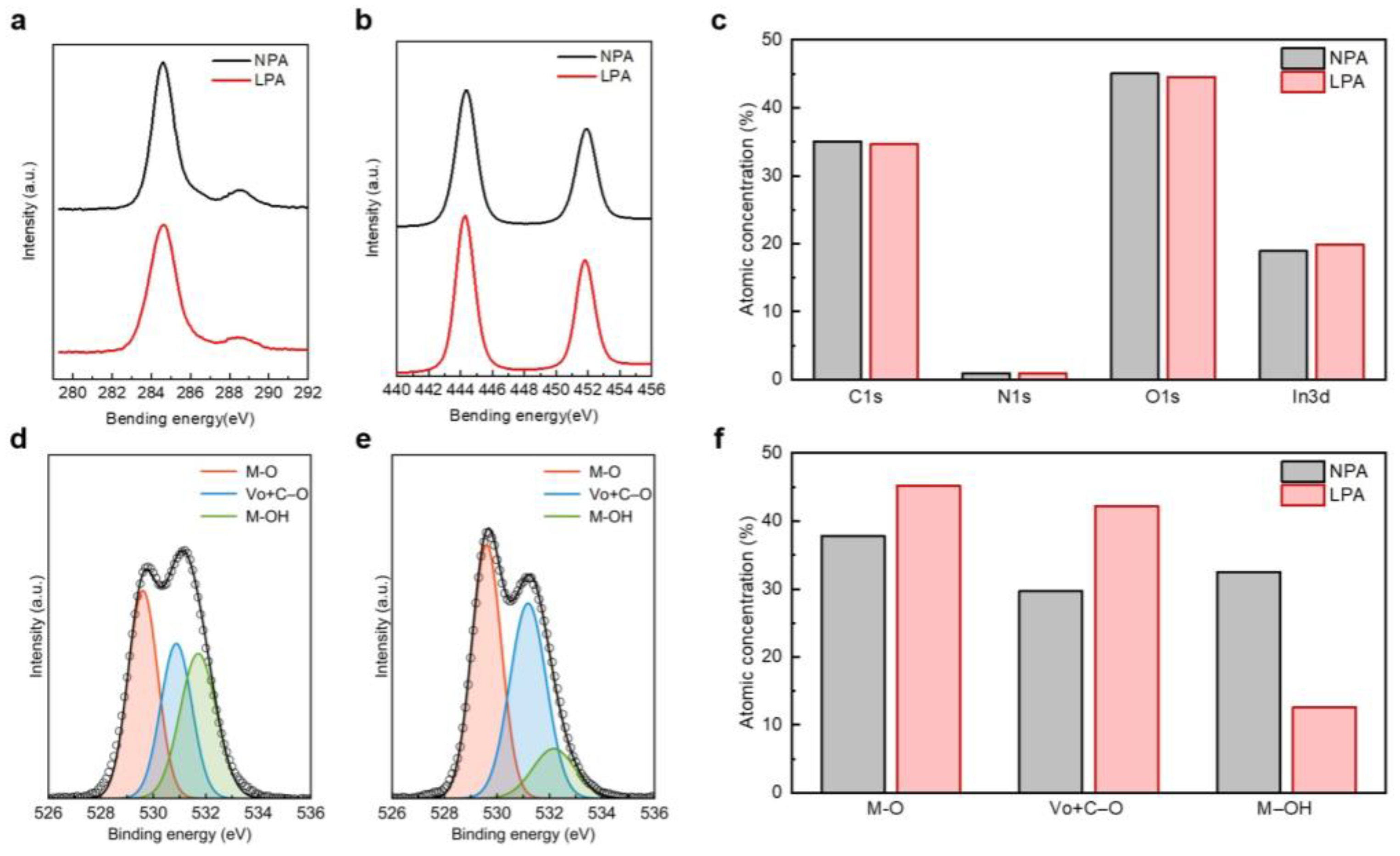
XPS analysis was conducted to illustrate the impact of LPA on the atomic composition in the InOx semiconductor. Figure 2a,b presents the XPS C 1s and In 3d spectra of NPA and LPA InOx thin films, respectively. Both NPA and LPA InOx thin films show clear peaks at 284.6 and 445.5 eV for C 1s and In 3d, respectively, and there is negligible difference in peak intensity. In addition, NPA and LPA InOx thin films show a similar atomic ratio of C, N, O, and In, as shown in Figure 2c. This result indicates that the LPA process does not induce the diffusing out of byproducts, such as nitrogen or carbon. Figure 2d,e shows the deconvoluted XPS O 1s spectra of NPA InOx and LPA InOx, respectively. Three main peaks were observed at the ~529.6, ~530.5, and ~531.5 eV positions, corresponding to metal–oxygen (M–O), oxygen atoms near oxygen vacancies and in M–OC bonds (Vo + C–O), and metal hydroxide (M–OH), respectively [16,18,19,20]. Compared to NPA InOx, LPA InOx showed a relatively increased ratio of M–O bonding to Vo + C–O, and in particular, M–OH bonding was significantly reduced, as shown in Figure 2d,e. NPA InOx and LPA InOx have M–OH bonding of 33% and 12.6%, respectively (Figure 2f). In the process of etching with pure water, a large amount of M–OH was formed in InOx due to the additional supply of water molecules by the water etchant. The annealing temperature is not high enough for the condensation reaction. As a result, M–OH still remains in InOx [21]. On the other hand, the low M–OH ratio in LPA InOx results from the diffusing out of hydrogen via thermal annealing in a vacuum environment [22]. Although annealing temperature is 200 °C the same as NPA InOx, the vacuum environment assists in the effective removal of hydrogen, thereby leading to an increase in the M–O bond. The M–O increases from 38.0% to 45.2% through LPA. In general, in oxide semiconductors, hydroxyl acts as an acceptor-like trap and hinders electron conduction, while the M–O network provides an electron transport path through the overlap of metal s orbitals [23]. Therefore, it is necessary to minimize the M–OH and enhance the M–O network in the oxide semiconductor for high-performance electronic devices. Meanwhile, vacuum induces not only the diffusing out of hydrogen but also the desorption of oxygen from the surface [24]. This desorption of oxygen consequently promotes the formation of Vo + C–O and improves the conductivity of the semiconductor. The introduction of LPA led to an increase in Vo + C–O from 30.0% to 42.2%.

3.2. Physical Properties of InOx Semiconductor Thin Films

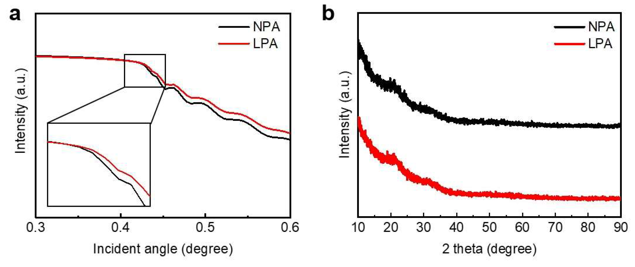
XRR analysis was performed to investigate the effect of LPA on the density of InOx semiconductor films. Figure 3a shows the XRR spectra of NPA and LPA InOx. The mass density of a thin film is related to the critical angle (θc). Equation (1) shows that there is a proportional relationship between the density and θc [25]:
θ c 2 = ( e 2 λ 2 π m c 2 ) · ( N A Z A ) D
where NA is Avogadro’s number, λ is the X-ray wavelength, Z is the average number of electrons per atom, A is the average atomic mass, and D is the mass density of the film. As shown in Figure 3a, the critical angle of LPA InOx is positively shifted. The extracted film densities of NPA InOx and LPA InOx are 5.19 and 5.45, respectively, indicating that the LPA treatment increases the film density. In other words, the LPA treatment induces dense M–O bonds by diffusing out of hydrogen ions and suppresses physical defects, such as pinholes and pores [26,27]. This result agrees with the XPS analysis.
Figure 3b shows the GIXRD spectra for NPA InOx and LPA InOx thin films. No clear peaks were observed for both NPA InOx and LPA InOx, indicating that the thin films have an amorphous phase [28]. Binary oxide semiconductors, such as InOx, typically have poly- or nanocrystalline structures, even at low processing temperatures [9]. Furthermore, since the poly- or nanocrystalline structure of semiconductors has grain boundaries, the yield and uniformity of devices in mass production are decreased. Therefore, the amorphous phase could be preferred in the industry. The amorphous phase of NPA InOx and LPA InOx might be attributed to the fact that additional water molecules are supplied in the initial stage of thin film formation through the water etching process to hinder InOx crystallization [15,29].
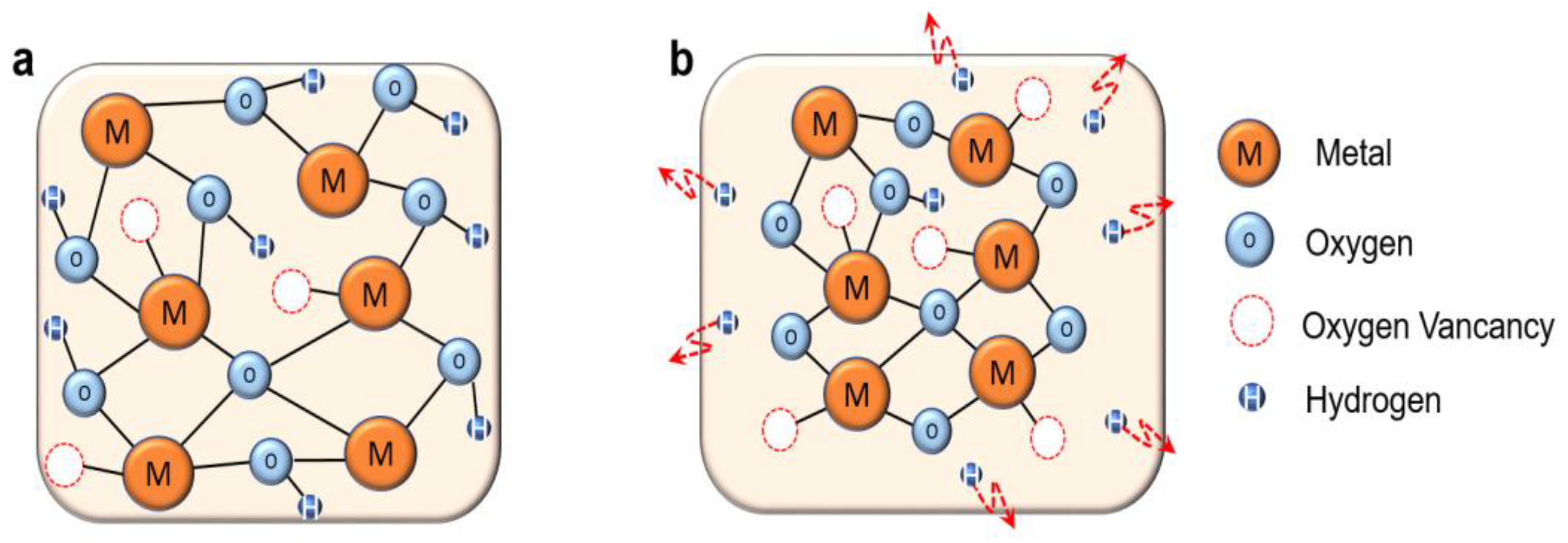
The proposed chemical mechanism of LPA effect on InOx is illustrated in Figure 4. NPA InOx contains hydrogen-related defects as well as the M-O network due to insufficient thermal energy (Figure 4a). These OH-related defects not only lead to an increase in the electron concentration in the semiconductor but also act as acceptor-like traps [11,30]. In addition, the high ratio of M-OH weak bonds and the low mass density is induced due to insufficient condensation and densification. Such an imperfect atomic structure of NPA InOx can be understood through the results of XPS and XRR, which were discussed above. On the other hand, in LPA InOx, film activation based on the condensation reaction is effectively achieved due to the diffusing out of hydrogen in the weakly bonded O–H (Figure 4b). As a result, M–O bonding increases and defects decrease, thereby forming a favorable semiconducting film. The following Equation (2) represents the condensation reaction:
M–OH + M–OH → M–O–M + H2O

3.3. Electrical Characteristics of LPA InOx TFTs

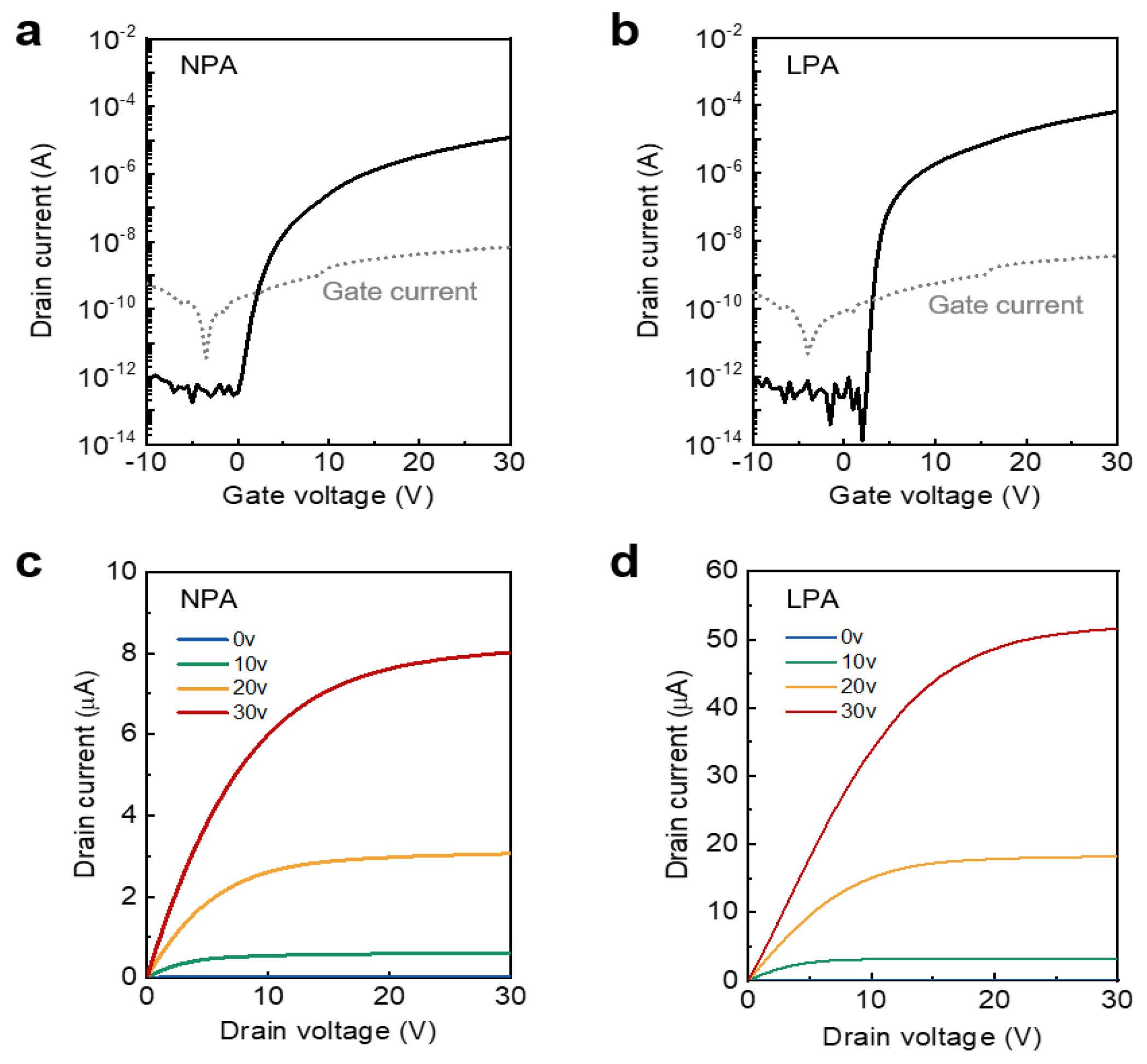
The transfer and output characteristics of the device were investigated to examine the effect of LPA on the electrical properties of InOx TFTs. Figure 5a,b shows the transfer characteristics of NPA and LPA InOx TFTs, respectively. To obtain the transfer curves, the gate voltage was increased from −10 to 30 V, while the drain voltage was maintained at 30 V. Surprisingly, the µFE of the LPA InOx TFTs showed a high value of 0.81 cm2 V−1 s−1 despite the low processing temperature and amorphous phase. This value is about six times higher than the µFE of NPA InOx TFT, 0.13 cm2 V−1 s−1. Note that there is a trade-off relationship between annealing temperature and mobility, and Vth and mobility in oxide semiconductor system due to the charge transport mechanism [15,31]. Thus, the µFE of oxide TFTs in this study could be dramatically increased by increasing the annealing temperature or semiconductor thickness, although this study is focused on the low processing temperature and enhancement-mode operation. Furthermore, the introduction of LPA leads to an increase in the on/off current ratio from 6.83 × 10⁷ to 4.91 × 10⁹. The subthreshold slope (SS), which is related to the interface trap density, also greatly decreased from 0.71 V dec−1 to 0.28 V dec−1. Considering the above chemical and physical analysis results, the increase in M–O bonds acting as a charge transport path and the decrease in M–OH bonds serving as trap sites through the LPA treatment are the dominant factors that cause the changes in the electrical properties. Figure 5c,d shows the output characteristics of NPA and LPA InOx TFTs, respectively. The output curves were measured by applying the gate voltage from −10 to 30 V in 10 V steps. Drain voltage was swept from 0 to 30 V. LPA InOx TFT showed significantly higher drain current than NPA InOx TFT under the same voltage conditions, and both devices showed clear linear and saturation regions. The electrical parameters of LPA oxide TFTs and recently reported oxide TFTs are summarized in Table 1.

3.4. Bias Stress-Induced Instability of LPA InOx TFTs

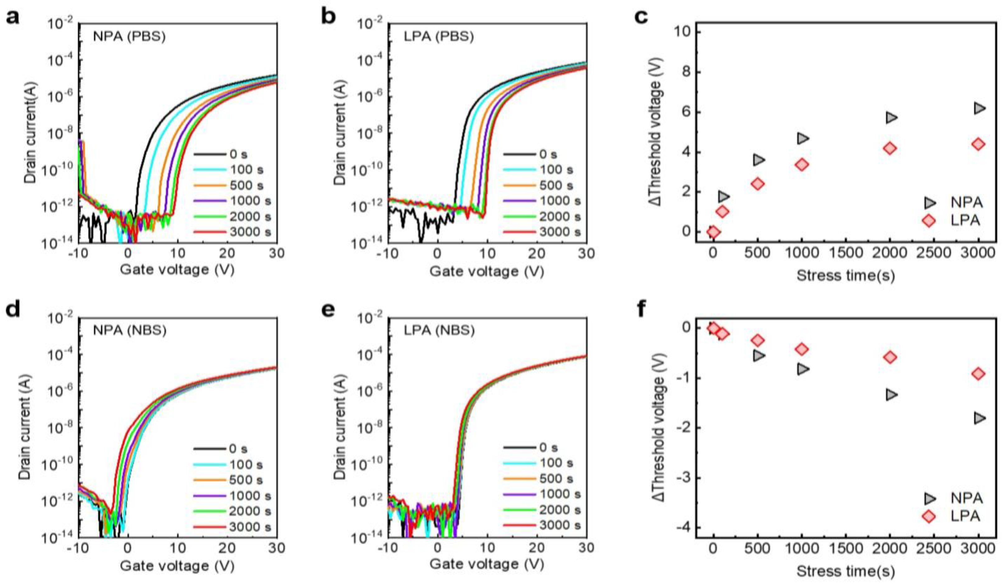
Since the bias stress-induced instability directly affects the lifetime of the device, ensuring bias stability is one of the most important factors in determining its commercialization. The effects of LPA on the stability of TFTs under positive bias stress (PBS) and negative bias stress (NBS) are investigated. Figure 6a,b shows the PBS time-dependence of transfer curves of NPA and LPA InOx TFTs, respectively. Gate and drain voltages of 10 V and 0 V, respectively, were applied to the PBS test. The ΔVth of NPA and LPA InOx TFTs were 6.20 and 4.40 V, respectively (Figure 6c). LPA InOx TFTs exhibited superior PBS stability compared to NPA InOx TFTs. In both devices, SS does not change as the stress time increases, and only a positive Vth shift was confirmed. This suggests that the degradation caused by PBS is due to electron trapping at gate dielectricthe presence of InOx semiconductor interfaces and electron injection into gate dielectric rather than defect creation [38,39]. Since the thermally grown high-quality SiO2 was used for the gate dielectric of NPA and LPA InOx TFTs, the improvement in ΔVth through LPA implies the reduction in electron trapping at the interface. Recently, it has been revealed that excess hydrogen peroxide could be the origin of PBS-induced Vth degradation [4]. However, since solution-processed InOx is characterized by a relatively oxygen-poor configuration, unlike IGZO sputtered at high oxygen flow rates, oxygen-related defects cannot be considered the origin of PBS-induced ΔVTH. Therefore, it is reasonable that the reduction in hydrogen-related defects through LPA leads to the improvement of PBS in oxide TFTs based on the XRR and XPS results. Figure 6c,d shows the NBS time-dependent transfer curves of NPA and LPA InOx TFTs, respectively. The gate and drain voltages of −10 V and 0 V, respectively, were utilized for the NBS test. After 3000 s of NBS, the ΔVth of NPA and LPA InOx TFTs were −1.8 and −0.91 V, respectively, and LPA InOx TFTs showed superior NBS stability compared to NPA InOx TFTs (Figure 6f). Hole trapping, oxygen vacancy, and excess hydrogen peroxide models have been considered mechanisms of Vth deterioration via NBS [4,38,39]. It is known that SS deterioration generally occurs based on oxygen vacancy or peroxide model under a strong negative gate bias or illumination stress [4,38,40]. Since the negative shift of Vth is observed without changing SS in this study, the shift of Vth in NPA and LPA InOx TFTs might be attributed to hole trapping and injection rather than the ionization of oxygen vacancy. Therefore, the superior NBS stability of LPA InOx TFTs originates from the reduction in organic chemical- and hydrogen-related defects, which could act as hole-trapping states [26,41]. Although the PBS and NBS were analyzed at room temperature in this study, the stress temperature also highly affected the Vth shift by accelerating the activation of defects. Thus, the PBS- and NBS-induced instability could deteriorate as the stress temperature increases based on the stretched exponential function [42,43].

4. Conclusions

In conclusion, the LPA method is suggested for the low-temperature annealing of the InOx semiconductor. The enhancement-mode amorphous InOx TFTs were successfully fabricated using a solution process at a low process temperature of 200 °C. Through XPS analysis, LPA was able to greatly reduce the M–OH ratio, and the defective bonding states, in InOx from 33% to 12.6%. As a result, the introduction of LPA leads to the significant improvement of μFE and SS from 0.13 to 0.81 cm2 V−1 s−1 and from 0.71 to 0.28 V dec−1, respectively. In addition, the LPA InOx TFTs exhibited stable operation under PBS and NBS compared to the control device.

Author Contributions

Conceptualization, W.P. and D.K.; methodology, W.P. and J.P.; validation, W.P., D.K. and J.-H.B.; formal analysis, W.P. and J.L.; investigation, D.K., W.P. and J.P.; data curation, W.P., J.N. and J.E.; writing—original draft preparation, W.P. and D.K.; writing—review and editing, D.K., J.J. and J.-H.B.; visualization, D.K.; supervision, S.-H.L., I.M.K. and J.-H.B.; project administration, J.-H.B. All authors have read and agreed to the published version of the manuscript.

Funding

This work was supported by a National Research Foundation of Korea (NRF) grant funded by the Korean government (MSIT) (2021R1A2C1011429). This research was also supported by the MSIT (Ministry of Science and ICT), Korea, under the Innovative Human Resource Development for Local Intellectualization support program (IITP-2023-RS-2022-00156389), supervised by the IITP (Institute for Information and Communications Technology Planning and Evaluation).

Data Availability Statement

Not applicable.

Conflicts of Interest

The authors declare no conflict of interest.

References

  1. Fortunato, E.; Barquinha, P.; Martins, R. Oxide semiconductor thin-film transistors: A review of recent advances. Adv. Mater. 2012, 24, 2945–2986. [Google Scholar] [CrossRef] [PubMed]
  2. Yu, X.; Marks, T.J.; Facchetti, A. Metal oxides for optoelectronic applications. Nat. Mater. 2016, 15, 383–396. [Google Scholar] [CrossRef] [PubMed]
  3. Si, M.; Lin, Z.; Sun, X.; Wang, H.; Ye, P.D. Scaled indium oxide transistors fabricated using atomic layer deposition. Nat. Electron. 2022, 5, 164–170. [Google Scholar] [CrossRef]
  4. Park, J.S.; Maeng, W.J.; Kim, H.S.; Park, J.S. Review of recent developments in amorphous oxide semiconductor thin-film transistor devices. Thin Solid Film. 2012, 520, 1679–1693. [Google Scholar] [CrossRef]
  5. Xu, W.; Li, H.; Xu, J.-B.; Wang, L. Recent Advances of Solution-Processed Metal Oxide Thin-Film Transistors. ACS Appl. Mater. Interfaces 2018, 10, 25878–250901. [Google Scholar] [CrossRef]
  6. Park, W.P.; Kang, B.H.; Kim, H.J. A Review of Low-Temperature Solution-Processed Metal Oxide Thin-Film Transistors for Flexible Electronics. Adv. Funct. Mater. 2020, 30, 1904632. [Google Scholar] [CrossRef]
  7. Fukuda, K.; Someya, T. Recent Progress in the Development of Printed Thin-Film Transistors and Circuits with High-Resolution Printing Technology. Adv. Mater. 2016, 29, 1524–4095. [Google Scholar] [CrossRef]
  8. Ahn, B.D.; Jeon, H.J.; Sheng, J.; Park, J.; Park, J. A review on the recent developments of solution processes for oxide thin film transistors. Semicond. Sci. Technol. 2015, 30, 268–1242. [Google Scholar] [CrossRef]
  9. Kamiya, T.; Hosno, H. Material characteristics and applications of transparent amorphous oxide semiconductors. NPG Asia Mater. 2010, 2, 15–22. [Google Scholar] [CrossRef] [Green Version]
  10. Kim, H.S.; Byrne, P.D.; Facchetti, A.; Marks, T.J. High Performance Solution-Processed Indium Oxide Thin-Film Transistors. J. Am. Chem. Soc. 2008, 130, 12580–12581. [Google Scholar] [CrossRef]
  11. Choi, S.; Park, J.; Hwang, S.H.; Kim, C.; Kim, Y.-S.; Oh, S.; Baeck, J.H.; Bae, J.U.; Noh, J.; Lee, S.W.; et al. Excessive Oxygen Peroxide Model-Based Analysis of Positive-Bias-Stress and Negative-Bias-Illumination-Stress Instabilities in Self-Aligned Top-Gate Coplanar In–Ga–Zn–O Thin-Film Transistors. Adv. Electron. Mater. 2022, 8, 2101062. [Google Scholar] [CrossRef]
  12. Sohna, Y.; Moon, G.; Choi, K.; Kim, Y.S.; Park, K.C. Effects of TFT mobility variation in the threshold voltage compensation circuit of the OLED display. J. Inf. Disp. 2016, 18, 25–30. [Google Scholar] [CrossRef] [Green Version]
  13. Buchholz, D.B.; Ma, Q.; Alducin, D.; Ponce, A.; Yacaman, M.J.; Khanal, R.; Medvedeva, J.E.; Chang, R. The Structure and Properties of Amorphous Indium Oxide. ACS Appl. Mater. Interfaces 2014, 26, 5401–5411. [Google Scholar] [CrossRef] [Green Version]
  14. Babu, S.H.; Kaleemulla, S.; Madlhusudhana, N.; Krishnamoorthi, C. Indium oxide: A transparent, conducting ferromagnetic semiconductor for spintronic applications. J. Magn. Magn. Mater. 2016, 416, 66–74. [Google Scholar] [CrossRef]
  15. Kim, D.-K.; Seo, K.H.; Kwon, D.H.; Jeon, S.H.; Hwang, Y.J.; Wang, Z.; Park, J.H.; Lee, S.H.; Jang, J.W.; Kang, I.M.; et al. Viable strategy to minimize trap states of patterned oxide thin films for both exceptional electrical performance and uniformity in sol–gel processed transistors. J. Chem. Eng. 2022, 441, 66–74. [Google Scholar] [CrossRef]
  16. Kim, Y.H.; Heo, J.S.; Kim, T.H.; Park, S.J.; Yoon, M.H.; Kim, J.W.; Oh, M.S.; Yi, G.R.; Noh, Y.Y.; Park, S.K. Flexible metal-oxide devices made by room-temperature photochemical activation of sol–gel films. Nature 2012, 489, 128–132. [Google Scholar] [CrossRef]
  17. Heo, J.S.; Jo, J.W.; Kang, J.; Jeong, C.Y.; Jeong, H.Y.; Kim, S.K.; Kim, K.; Kwon, H.I.; Kim, J.Y.; Kim, Y.H.; et al. Water-Mediated Photochemical Treatments for Low-Temperature Passivation of Metal-Oxide Thin-Film Transistors. ACS Appl. Mater. Interfaces 2016, 8, 10403–10412. [Google Scholar] [CrossRef]
  18. Yeom, H.-I.; Ko, J.B.; Mun, G.; Park, S.-H.K. High mobility polycrystalline indium oxide thin-film transistors by means of plasma-enhanced atomic layer deposition. J. Mater. Chem. C 2016, 4, 6873–6880. [Google Scholar] [CrossRef] [Green Version]
  19. Socratous, J.; Kulbinder, K.; Vaynzof, Y.; Sadhanala, A.; Brow, A.; Sepe, A.; Steiner, U.; Sirringhaus, H. Electronic Structure of Low-Temperature Solution-Processed Amorphous Metal Oxide Semiconductors for Thin-Film Transistor Applications. Adv. Funct. Mater. 2015, 25, 1873–1885. [Google Scholar] [CrossRef] [Green Version]
  20. Meng, Y.; Liu, G.; Liu, A.; Song, H.; Hou, Y.; Shinb, B.; Shan, F. Low-Temperature Fabrication of High Performance Indium Oxide Thin Film Transistors Condensation annealing temp. RSC Adv. 2015, 5, 37807–37813. [Google Scholar] [CrossRef]
  21. Zhu, M.; Huang, H.; Gong, J.; Sun, C.; Jiang, X. Role of oxygen desorption during vacuum annealing in the improvement of electrical properties of aluminum doped zinc oxide films synthesized by sol gel method. J. Appl. Phys. 2007, 102, 102–107. [Google Scholar] [CrossRef]
  22. Xie, J.Z.; Murarka, S.P.; Guo, X.S.; Lanford, W.A. Stability of hydrogen in silicon nitride films deposited by low-pressure and plasma enhanced chemical vapor deposition techniques. J. Vac. Sci. Technol. B Mater. 1989, 25, 150–152. [Google Scholar] [CrossRef]
  23. Wang, H.; Li, P.; Chen, Z.; Yang, B.; Wei, B.; Fu, C.; Ding, X.; Zhang, J. Physico-Chemical Origins of Electrical Characteristics and Instabilities in Solution-Processed ZnSnO Thin-Film Transistors. Coatings 2022, 12, 1534. [Google Scholar] [CrossRef]
  24. Jeon, J.W.; Um, J.G.; Lee, S.; Jang, J. Control of O-H bonds at a-IGZO/SiO2 interface by long time thermal annealing for highly stable oxide TFT. AIP Adv. 2017, 7, 125110. [Google Scholar] [CrossRef]
  25. Liu, X.; Xu, H.; Ning, H.; Lu, K.; Zhang, H.; Zhang, X.; Yao, R.; Fang, Z.; Lu, X.; Peng, J. Induced nano-scale self-formedmetal-oxide interlayer in amorphous silicon tin oxide thin flm transistors. Sci. Rep. 2018, 7, 4160. [Google Scholar] [CrossRef] [PubMed]
  26. Kwon, J.M.; Jung, J.; Rim, Y.S.; Kim, D.L.; Kim, H.J. Improvement in Negative Bias Stress Stability of Solution-Processed Amorphous In–Ga–Zn–O Thin-Film Transistors Using Hydrogen Peroxide. ACS Appl. Mater. Interfaces 2014, 6, 3371–3377. [Google Scholar] [CrossRef]
  27. Rim, Y.S.; Jeong, W.H.; Kim, D.L.; Lim, H.S.; Kim, K.M.; Kim, H.J. Simultaneous modification of pyrolysis and densification for low-temperature solution-processed flexible oxide thin-film transistors. J. Mater. Chem. 2012, 22, 12491–12497. [Google Scholar] [CrossRef]
  28. Arulkumar, S.; Parthiban, S.; Kwon, J.Y.; Uraoka, Y.; Bermundo, J.P.S.; Mukherjee, A.; Das, B. High mobility silicon indium oxide thin-film transistor fabrication by sputtering process. Vacuum 2022, 199, 110963. [Google Scholar] [CrossRef]
  29. Park, W.T.; Son, I.Y.; Park, H.W.; Chung, K.B.; Xu, Y.; Lee, T.; Noh, Y.Y. Facile Routes to Improve Performance of Solution-Processed Amorphous Metal Oxide Thin Film Transistors by Water Vapor Annealing. ACS Appl. Mater. Interfaces 2015, 24, 13289–13294. [Google Scholar] [CrossRef]
  30. Chang, J.; Chang, K.L.; Chi, C.; Zhang, J.; Wu, J. Water induced zinc oxide thin film formation and its transistor performance. J. Mater. Chem. C 2014, 2, 5397–5403. [Google Scholar] [CrossRef]
  31. Faber, H.; Das, S.; Lin, Y.-H.; Pliatsikas, N.; Zhao, K.; Kehagias, T.; Dimitrakopulos, G.; Amassian, A.; Patsalas, P.A.; Anthopoulos, D.A. Heterojunction oxide thin-film transistors with unprecedented electron mobility grown from solution. Sci. Adv. 2017, 3, e1602640. [Google Scholar] [CrossRef] [PubMed] [Green Version]
  32. Ting, C.-C.; Fan, H.-Y.; Tsai, M.-K.; Li, W.-Y.; Yong, H.-E.; Lin, Y.-F. Improvement of electrical characteristics in the solution-processed nanocrystalline indium oxide thin-film transistors depending on yttrium doping concentration. Mater. Sci. Appl. 2013, 211, 800–810. [Google Scholar] [CrossRef]
  33. Kim, G.H.; Ahn, D.B.; Shin, H.S.; Jeong, W.H.; Kim, H.J.; Kim, H.J. Effect of indium composition ratio on solution-processed nanocrystalline InGaZnO thin film transistors. Appl. Phys. Lett. 2009, 94, 233501. [Google Scholar] [CrossRef] [Green Version]
  34. Lee, J.S.; Song, S.M.; Kim, Y.H.; Kwon, J.Y.; Han, M.K. Effects of O2 plasma treatment on low temperature solution-processed zinc tin oxide thin film transistors. Mater. Sci. Appl. 2013, 210, 1745–1749. [Google Scholar] [CrossRef]
  35. Hsu, C.-C.; Chou, C.-H.; Chen, Y.-T.; Jhang, W.-C. A Study of Solution-Processed Zinc–Tin-Oxide Semiconductors for Thin-Film Transistors. IEEE Trans. Electron. Devices 2019, 66, 2631–2636. [Google Scholar] [CrossRef]
  36. Sabri, M.M.; Jung, J.; Yoon, D.H.; Yoon, S.; Tak, Y.J.; Kim, H.J. Hydroxyl radical-assisted decomposition and oxidation in solution-processed indium oxide thin-film transistors. J. Mater. Chem. C 2015, 3, 7499–7505. [Google Scholar] [CrossRef]
  37. Hwang, Y.-J.; Kim, D.-K.; Jeon, S.-H.; Park, J.; Lee, S.-H.; Jang, J.; Kang, I.M.; Bae, J.H. Importance of Structural Relaxation on the Electrical Characteristics and Bias Stability of Solution-Processed ZnSnO Thin-Film Transistors. Nanomaterials 2022, 12, 3097. [Google Scholar] [CrossRef]
  38. Kim, H.J.; Je, S.Y.; Won, J.Y.; Baek, H.J.; Jeon, J.K. Effect of antimony doping on the low-temperature performance of solu-tion-processed indium oxide thin film transistors. Phys. Status Solidi 2014, 8, 924–927. [Google Scholar]
  39. Jeong, J.K. Photo-bias instability of metal oxide thin film transistors for advanced active matrix displays. J. Meter. Res. 2013, 28, 16. [Google Scholar] [CrossRef]
  40. Janotti, A.; Walle, C.G.V. Oxygen vacancies in ZnO. Appl. Phys. Lett. 2005, 87, 122102. [Google Scholar] [CrossRef]
  41. Ide, K.; Nomura, K.; Hosono, H.; Kamiya, T. Electronic Defects in Amorphous Oxide Semiconductors: A Review. Phys. Status Solidi A 2019, 216, 1800372. [Google Scholar] [CrossRef]
  42. Choi, S.; Jang, J.; Kang, H.; Baeck, J.H.; Bae, J.U.; Park, K.S.; Yoon, S.H.; Kang, I.B.; Kim, D.M.; Choi, S.J.; et al. Systematic Decomposition of the Positive Bias Stress Instability in Self-Aligned Coplanar InGaZnO Thin-Film Transistors. IEEE Elec. Dev. Lett. 2017, 38, 580–583. [Google Scholar] [CrossRef]
  43. Yang, G.W.; Park, J.; Choi, S.; Kim, C.; Kim, D.M.; Choi, S.-J.; Bae, J.H.; Cho, H.; Kim, D.H. Total Subgap Range Density of States-Based Analysis of the Effect of Oxygen Flow Rate on the Bias Stress Instabilities in a-IGZO TFTs. IEEE Trans. Electron. Devices 2022, 69, 166–173. [Google Scholar] [CrossRef]
Figure 1. Fabrication process of low-temperature amorphous InOx TFTs using LPA.
Nanomaterials 13 02231 g001
Figure 2. XPS (a) C 1s and (b) In 3d spectra of NPA and LPA InOx thin films. (c) The comparison of the atomic percentages of C 1s, N 1s, O 1s, and In 3d of NPA and LPA InOx. XPS O 1 s spectra of (d) NPA InOx and (e) LPA InOx thin films. (f) The comparison of the atomic percentages of M–O, Vo + C–O, and M–OH of NPA and LPA InOx.
Nanomaterials 13 02231 g002
Figure 3. (a) XRR and (b) GIXRD spectra of NPA InOx (black line) and LPA InOx (red line).
Nanomaterials 13 02231 g003
Figure 4. (a) NPA InOx TFT and (b) LPA InOx TFT, Proposed mechanism for the effect of LPA on the atomic structure and film formation of InOx.
Nanomaterials 13 02231 g004
Figure 5. Transfer characteristics of (a) NPA InOx TFTs and (b) LPA InOx TFTs. The gray line indicates gate leakage current. Output characteristics of (c) NPA InOx TFTs and (d) LPA InOx TFTs.
Nanomaterials 13 02231 g005
Figure 6. Transfer curve shifts of (a) NPA InOx TFTs and (b) LPA InOx TFTs under PBS. (c) Threshold voltage shift of NPA and LPA TFTs via PBS. Transfer curve shifts of (d) NPA InOx TFTs and (e) LPA InOx TFTs under NBS. (f) Threshold voltage shift of NPA and LPA TFTs via NBS.
Nanomaterials 13 02231 g006
Table 1. Comparison with oxide TFTs.
SemiconductorDielectricT (°C)Vth (V)μFE (cm2 V−1 s−1)SS (V dec−1)Ion/OffReference
InOxSiO25006.740.950.241.55 × 105[32]
InGaZnOSiO2450−5.091.251.055.2 × 103[33]
ZnSnOSiO235010.70.58-~1 × 10⁶[34]
ZnSnOSiO2600-1.120.393.0 × 107[35]
InOxSiO2240-1.570.453.9 × 107[36]
ZnSnOSiO2500−0.952.411.253.9 × 106[37]
InSbOSiO23001.94.600.293 × 107[38]
InOxSiO22004.400.810.284.91 × 109This study
Disclaimer/Publisher’s Note: The statements, opinions and data contained in all publications are solely those of the individual author(s) and contributor(s) and not of MDPI and/or the editor(s). MDPI and/or the editor(s) disclaim responsibility for any injury to people or property resulting from any ideas, methods, instructions or products referred to in the content.