Abstract
Herein, we reported the simulation study of lead (Pb)-free all-perovskite tandem solar cells using SCAPS-1D. Tandem solar cells are comprised of two different cells which are known as the top cell and the bottom cell. We simulated tandem solar cells using methyl ammonium germanium iodide (MAGeI3) as the top subcell absorber layer due to its wide band gap of 1.9 eV. Further, FA0.75MA0.25Sn0.25Ge0.5I3 = FAMASnGeI3 was used as the bottom subcell absorber layer due to its narrow band gap of 1.4 eV. The tandem solar cells were simulated with MAGeI3 as the top cell and FAMASnGeI3 as the bottom subcell using SCAPS-1D. Various electro-transport layers (ETLs) i.e., titanium dioxide, tin oxide, zinc oxide, tungsten trioxide, and zinc selenide, were used to examine the impact of ETL on the efficiency of tandem solar cells. The observations revealed that TiO2 and ZnSe have more suitable band alignment and better charge-extraction/transfer properties. A reasonably improved efficiency of 23.18% and 22.4% have been achieved for TiO2 and ZnSe layer-based tandem solar cells, respectively.
1. Introduction
The energy crisis is one of the major challenges for the scientific community which needs significant attention [1,2,3]. Current energy resources are limited, which may be responsible for energy crises in the future [4,5,6]. Hence, it is important to find renewable energy sources to overcome the issue of the energy crisis [7]. Solar energy is one of the most abundant energy sources which can be a suitable candidate for the production of neat and clean energy [8,9,10]. Solar energy can be directly converted and transformed into electrical energy via photovoltaic cells (solar cells) [11]. In the past few decades, various solar cells such as dye-sensitized solar cells, organic solar cells, thin film solar cells, silicon-based solar cells, polymer solar cells, bulk-heterojunction solar cells, quantum dot solar cells, and perovskite solar cells (PSCs) have been developed [3,7,12,13]. At present, silicon-based solar cells are widely used in practical applications but their fabrication process is quite complicated [3]. In addition, silicon-based solar cells are expensive, and it is important to reduce the cost of solar cells [7]. In this connection, a new visible light sensitizer (methyl ammonium lead halide = MAPbX3; X = halide anion) was explored in the fabrication of dye-sensitized solar cells [14]. This MAPbX3-based dye-sensitized solar cell device exhibited power conversion efficiency (PCE) of less than 4% [14]. However, it was further improved to more than 25% by employing extensive efforts and novel approaches [8]. Unfortunately, a single-junction solar cell has some drawbacks such as sub-bandgap and thermalization losses [15]. Additionally, it has been found that single-junction solar cells cannot exceed the Shockley–Queisser (SQ) single-junction limit proposed by SQ in 1961 [16]. Thus, tandem solar cells have been developed which may be a more suitable and efficient alternative to silicon-based solar cells [15]. In this connection, all-perovskite tandem solar cells have been developed by various research groups which showed decent performance [17,18,19,20,21]. Lead halide-based perovskite materials have been used in the fabrication of tandem solar cells, but the presence of toxic lead (Pb) still remains a concern for their practical applications [19]. In further studies, Pb-free perovskite materials such as methyl ammonium bismuth iodide, methyl ammonium antimony iodide, methyl ammonium tin iodide (MASnI3), or methyl ammonium germanium iodide (MAGeI3) have been explored in the construction of single-junction PSCs or tandem solar cells [22,23,24,25,26,27,28,29,30]. The reports suggested that Sn- or Ge-based perovskite materials have excellent optoelectronic features and a less toxic nature [30]. Thus, Sn- or Ge-based materials could be the alternative to lead-based perovskite materials [29].
Recently, numerical simulations of single-junction PSCs and tandem solar cells using SCAPS-1D have received enormous attention, and a large number of publications have been reported [31,32,33,34,35,36,37,38]. In this connection, Pandey et al. [37] simulated tandem solar cells by exploring CH3NH3Pb0.5Sn0.5I3 and Cs2AgBi0.75Sb0.25Br6 as the bottom cell and top cell, respectively. The simulated tandem solar cells exhibited a decent short-circuit current density (Jsc) of 15.21 mA/cm2 with an excellent open circuit voltage (Voc) of 1.95 V. A high PCE of 21.9% was reported for the simulated tandem solar cell architecture [37]. Further, Madan et al. [38] also simulated tandem solar cells using SCAPS-1D. Madan et al. [38] used FACsPb0.5Sn0.5I3 as the top cell layer and Cs2AgBi0.75Sb0.25Br6 as the bottom cell layer. The authors achieved an interesting Jsc of 14.9 mA/cm2, Voc of 1.83 V, and PCE of 17.3% using SCAPS-1D. In 2022, MASnI3 and MASnIBr2 were used as the bottom and top cell materials by Abdelaziz et al. [15]. The authors reported a good PCE of 15.6% which included a Jsc of 13.94 mA/cm2 and Voc of 1.89 V. The above results indicate that simulation of tandem solar cells using SCAPS-1D may be useful for the scientific community.
In the present work, our group reports the simulation study on the development of Pb-free all-perovskite tandem solar cells with MAGeI3 as the top subcell and FAMASnGeI3 as the bottom subcell using SCAPS-1D. The obtained results exhibited the presence of an excellent PCE of 22.4% for the simulated Pb-free all-perovskite tandem solar cells.
2. Device Structure and Simulation
Before the investigation of the photovoltaic performance of the all-perovskite tandem solar cell devices, we simulated the device with single-light-absorber layer devices using MAGeI3 or FAMASnGeI3 with ZnSe as the HTL using Cu2O as the HTL. The simulation parameters (band gap, dielectric permittivity, and electron affinity, etc.) and their used values for the simulation studies are presented in Tables S1 and S2. The simulation for all the devices were performed (illumination of AM 1.5 G; 100 mW/cm2; temperature = 300 K) using SCAPS-1D software developed by Prof. Marc Burgelman, Belgium [39]. In multi-junction tandem solar cells, two diodes are joined in a series to form the subcells. These joined diodes (subcells) generate the same current which is called the current of the tandem solar cells. Similarly, the sum of the voltage in the subcells is referred to as the voltage of the tandem solar cells. It is well known that SCAPS-1D could not fully support multi-junction tandem solar cells. Thus, the top and bottom subcells were separately simulated. In our simulations, the top subcell was illuminated using standard AM 1.5 G (1 sun conditions) and the bottom subcell was illuminated using the spectra filtered by the top subcell which can be described as below [40]:
where S(λ) = filtered spectrum; S0(λ) = spectrum incident on the top subcell; ai(λ) = absorption coefficient; and di is the thickness of the material. Under the above conditions, the Jsc of the two subcells was matched to simulate the tandem solar cells. We have also schematically described the simulation process in Figure S1 in the Supporting Information.
3. Results and Discussion
Photovoltaic Investigations
In the first stage, MAGeI3-based solar cells were simulated using SCAPS-1D. The performance of the MAGeI3-based solar cells was checked using a short-circuit current density (Jsc)–voltage (V) analysis. A schematic representation of the MAGeI3-based solar cell device architecture (FTO(500 nm)/ZnSe(50 nm)/MAGeI3(500 nm)/Cu2O(350 nm)) is shown in Figure 1A. The collected J–V graph of the simulated MAGeI3-based solar cell is presented in Figure 1B. The observations revealed that an excellent open circuit voltage (Voc) of 1.37 V can be achieved for MAGeI3-based PSCs with a PCE of 17.61%. In addition, the MAGeI3-based simulated device also showed a good Jsc value. The obtained photovoltaic parameters showed the promising performance of MAGeI3-based PSCs.
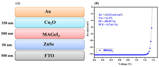
Figure 1.
Schematic device structure (A) and J–V curve (B) of MAGeI3-based PSCs.
In a further stage, another absorber layer (FAMASnGeI3) was used for the simulation studies. The device architecture (FTO(500 nm)/ZnSe(50 nm)/FAMASnGeI3(500 nm)/Cu2O(350 nm)) of the simulated solar cells is shown in Figure 2A. The FAMASnGeI3-based PSCs device was simulated under the same thickness and conditions. The obtained J–V graph of the simulated device is depicted in Figure 2B. The interesting PCE of 14.25% was obtained for the simulated FAMASnGeI3-based PSCs device. In addition, a decent Voc of 0.83 V and an excellent Jsc of 29.05 mA/cm2 were obtained. The J–V graph indicated that a high Jsc value of 29.05 mA/cm2 could be achieved for FAMASnGeI3-based PSCs compared to the MAGeI3-based PSCs. This also suggested that FAMASnGeI3 has a better light absorption property, which is related to the narrow band gap of FAMASnGeI3.
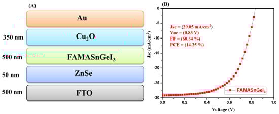
Figure 2.
Schematic device structure (A) and J–V curve (B) of FAMASnGeI3-based PSCs.
In the final step, we simulated Pb-free all-inorganic tandem solar cells using MAGeI3 and FAMASnGeI3 as the top and bottom subcells, respectively. The schematic diagram of the simulated tandem solar cell device is shown in Figure 3A. The collected J–V graph of the tandem solar cell device is shown in Figure 3B. According to Figure 3B, it can be noted that an improved PCE of 22.4% has been achieved. This revealed the potential of MAGeI3 and FAMASnGeI3 as the top and bottom subcell materials for the development of high performance Pb-free all-perovskite tandem solar cells.
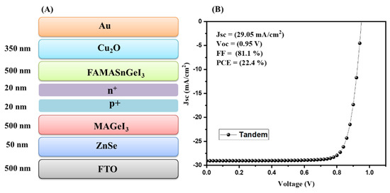
Figure 3.
Schematic device structure (A) and J–V curve (B) of tandem with ZnSe as the ETL.
The J–V characteristic and photovoltaic parameters of the MAGeI3, FAMASnGeI3, and tandem solar cell devices are summarized in Figure 4A,B, respectively. The simulated results exhibited that the Jsc values for the FAMASnGeI3 and tandem devices are the same. However, different Voc values were observed for the FAMASnGeI3 and tandem devices.
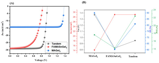
Figure 4.
J–V curves (A) and photovoltaic parameters (B) of MAGeI3, FAMASnGeI3, and tandem PSCs using ZnSe as the ETL.
The FAMASnGeI3-based PSCs device showed a lower value of Voc, whereas the highest value of Voc was observed for the MAGeI3-based PSCs with the lowest Jsc value. Thus, it can be clearly understood that combining the top and bottom cells improved the performance of the simulated tandem solar cells by reducing energy losses. However, MAGeI3 exhibited high Voc which is quite different. Further investigations and deep study are required to find out the reason behind this. In the above simulation studies, ZnSe was used as the ETL and Cu2O as the HTL. Thus, it is clear that the thickness of ZnSe and Cu2O may affect the photovoltaic performance of tandem solar cells. In this regard, we have studied the effect of the thickness of ZnSe and Cu2O layers. Therefore, we have investigated the influence of the thickness of ZnSe layer on the performance of tandem solar cell devices.
We used the same thickness of 500 nm for MAGeI3 and FAMASnGeI3 layers. A thickness of 350 nm was used for the Cu2O layer. The thickness of ZnSe was varied in the range of 50 to 100 nm. The collected J–V graphs of the simulated tandem solar cells device at various thicknesses of ZnSe of 50–100 nm are presented in Figure 5A, whereas the extracted photovoltaic parameters are summarized in Figure 5B. The simulated results demonstrated that the PCE of the tandem solar cells decreases with increasing thickness of the ZnSe layer from 50 nm to 100 nm. It can be considered that a thin layer of ZnSe (50 nm) has better charge transport properties and enhanced photovoltaic performance compared to the 70 nm or 100 nm thick ZnSe layer.
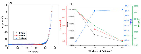
Figure 5.
J–V curves (A) and photovoltaic parameters (B) of tandem PSCs using ZnSe (with different thicknesses) as the ETL.
Hence, it can be stated that the 50 nm-thick ZnSe layer is the most promising ETL, and we used this 50 nm-thick ZnSe layer for further simulation studies. Similarly, the thickness of Cu2O was also varied from 150 nm to 500 nm for the simulation of tandem solar cells. The tandem solar cell devices were simulated using different thicknesses of 150–500 nm of the Cu2O layer and the obtained results are summarized in Figure 6.
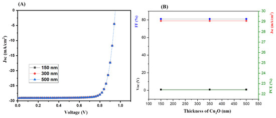
Figure 6.
J–V curves (A) and photovoltaic parameters (B) of tandem PSCs using ZnSe as the ETL with different thicknesses of Cu2O.
The J–V characteristics (Figure 6A) of the simulated tandem solar cells showed that the thickness of Cu2O HTL does not significantly alter the PCE (Figure 6B) of the tandem solar cells. Therefore, we used the optimized thickness of 350 nm for further numerical simulation studies.
The reported literature showed that the selection of a suitable ETL is of great significance to enhance the performance of solar cells. In this connection, we adopted different ETLs (TiO2, WO3, SnO2, and ZnO) for further simulation studies. The J–V characteristic curve of the TiO2-ETL-based tandem solar cells is displayed in Figure 7A which showed the presence of an excellent PCE of 23.18%. The photovoltaic parameters of the TiO2-ETL-based tandem solar cells are presented in Table S5.
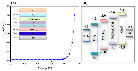
Figure 7.
J–V curve (A) and energy level diagram (B) of tandem solar cells with TiO2 as the ETL.
The energy level diagram of the TiO2-based tandem solar cells is inserted in Figure 7B. Further, we simulated tandem solar cells using SnO2 as the ETL layer. The obtained results using simulation studies for SnO2-ETL-based tandem solar cells are presented in Figure 8A. The J–V results showed that an interesting PCE of 16.78% can be achieved using SnO2 as the ETL layer.
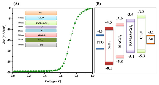
Figure 8.
J–V curve (A) and energy level diagram (B) of tandem solar cells with SnO2 as the ETL.
The photovoltaic parameters of the SnO2-ETL-based tandem solar cells are presented in Table S5. The energy level diagram of the simulated device is inserted in Figure 8B. Furthermore, a WO3-ETL-based tandem solar cell device was also simulated, and the J–V characteristic curve of the simulated device is presented in Figure 9A. A poor PCE of 10.52% was observed for the WO3-ETL-based tandem solar cells. The photovoltaic parameters of the WO3-ETL-based tandem solar cells are presented in Table S5. The energy level diagram of the simulated device is inserted in Figure 9B.
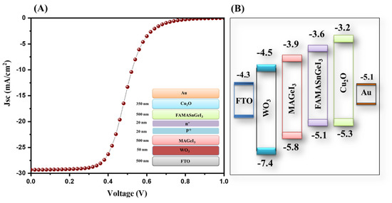
Figure 9.
J–V curve (A) and energy level diagram (B) of tandem solar cells with WO3 as the ETL.
Furthermore, we also simulated ZnO-ETL-based tandem solar cells, and the obtained J–V characteristic data of the simulated device is presented in Figure 10A. An improved PCE of 23.11% was obtained for the ZnO-ETL-based tandem solar cells. The photovoltaic parameters of the ZnO-ETL-based tandem solar cells are presented in Table S5. The energy level diagram of the simulated device is inserted in Figure 10B.
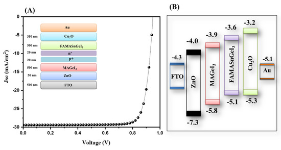
Figure 10.
J–V curve (A) and energy level diagram (B) of tandem solar cells with ZnO as the ETL.
The J–V characteristic of the ZnSe-ETL-based tandem solar cells is presented in Figure 11A.
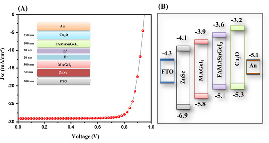
Figure 11.
J–V curve (A) and energy level diagram (B) of tandem solar cells with ZnSe as the ETL.
The observation revealed that the highest PCE of 22.40% was obtained for ZnSe as the ETL. The photovoltaic parameters of the ZnSe-ETL-based tandem solar cells are presented in Figure 11B. The energy level diagram of the simulated device is inserted in Figure 11B. The overall observations showed that TiO2 is the most suitable ETL layer, whereas ZnO- and ZnSe-based tandem solar cells also exhibited excellent PCE compared to the SnO2- or WO3-based tandem solar cell devices. The photovoltaic performance of different simulated tandem solar cells is provided in Tables S3–S5. The performance of the ZnSe-ETL-based tandem solar cells is compared with previous studies in Table 1. Our obtained results are comparable with previous reports as listed in Table 1. We believe that improved PCE of all-inorganic Pb free tandem solar cells can be achieved using further novel strategies [41].

Table 1.
Comparison of tandem solar cells with previous experimental and simulated reports [15,16,17,18,19,20,21,22,37,38].
4. Conclusions
It can be concluded that all-perovskite lead-free tandem solar cells have been numerically simulated using SCAPS-1D. MAGeI3 has a wide band of 1.9 eV, which makes it a suitable candidate for the fabrication of top cells. On the other hand, FAMASnGeI3 has a relatively narrow band gap of 1.4 eV, and it has been adopted as an absorber layer for the simulation of the bottom cell. All-perovskite tandem solar cells were simulated using MAGeI3 as the top cell and FAMASnGeI3 as the bottom cell materials. The thickness of the electron-transport layer (ZnSe) and hole-transport layer (Cu2O) was optimized, and an excellent efficiency of 22.4% was obtained using SCAPS-1D. Other electron transport layers such as ZnO, WO3, SnO2, and TiO2 were also used, and it was observed that an improved PCE of 23.18% can be achieved using TiO2 as the electron-transport layer.
Supplementary Materials
The following supporting information can be downloaded at: https://www.mdpi.com/article/10.3390/nano13010096/s1, Figure S1: Flow chart for the simulation of tandem solar cells; Table S1: Numerical parameters of different materials for device simulation; Table S2: Numerical parameters of different ETLs for device simulation; Table S3: Effect of thickness of ZnSe on photovoltaic parameters; Table S4: Effect of thickness of Cu2O on photovoltaic parameters; Table S5: Effect of different ETLs on photovoltaic parameters. References [32,42,43] are cited in the supplementary materials.
Author Contributions
Conceptualization, A.A. and H.A.; methodology, A.A. and H.A.; software, A.A. and H.A.; validation, A.A. and H.A.; formal analysis, H.A.; investigation, H.A.; resources, A.A.; data curation, H.A.; writing—original draft preparation, A.A. and H.A.; writing—review and editing, A.A.; supervision, A.A.; funding acquisition, A.A. All authors have read and agreed to the published version of the manuscript.
Funding
This work was funded by the the Deputyship for Research and Innovation, Ministry of Education, Saudi Arabia for financial support (project number IFKSURG-2-1339).
Data Availability Statement
Not applicable.
Acknowledgments
The authors gratefully acknowledged the Deputyship for Research and Innovation, Ministry of Education, Saudi Arabia for financial support (project number IFKSURG-2-1339).
Conflicts of Interest
We declare no conflict of interests.
References
- Zhang, X.; Cheng, X.; Zhang, Q. Nanostructured energy materials for electrochemical energy conversion and storage: A review. J. Energy Chem. 2016, 25, 967–984. [Google Scholar] [CrossRef]
- Ahmad, K.; Shinde, M.A.; Kim, H. Molybdenum disulfide/reduced graphene oxide: Progress in synthesis and electro-catalytic properties for electrochemical sensing and dye sensitized solar cells. Microchem. J. 2021, 169, 106583. [Google Scholar] [CrossRef]
- Devadiga, D.; Selvakumar, M.; Shetty, P.; Santosh, M.S. Recent progress in dye sensitized solar cell materials and photo-supercapacitors: A review. J. Power Sources 2021, 493, 229698. [Google Scholar] [CrossRef]
- Ahmad, K.; Mobin, S.M. Graphene oxide based planar heterojunction perovskite solar cell under ambient condition. New J. Chem. 2017, 41, 14253–14258. [Google Scholar] [CrossRef]
- Ahmad, K.; Shinde, M.A.; Song, G.; Kim, H. Design and fabrication of MoSe2/WO3 thin films for the construction of electrochromic devices on indium tin oxide based glass and flexible substrates. Ceram. Int. 2021, 47, 34297–34306. [Google Scholar] [CrossRef]
- Kabir, E.; Kumar, P.; Kumar, S.; Adelodun, A.A.; Kim, K.-H. Solar energy: Potential and future prospects. Renew. Sustain. Energy Rev. 2018, 82, 894–900. [Google Scholar] [CrossRef]
- Gong, J.; Li, C.; Wasielewski, M.R. Advances in solar energy conversion. Chem. Soc. Rev. 2019, 48, 1862–1864. [Google Scholar] [CrossRef]
- Jeong, J.; Kim, M.; Seo, J.; Lu, H.; Ahlawat, P.; Mishra, A.; Yang, Y.; Hope, M.A.; Eickemeyer, F.T.; Kim, M.; et al. Pseudo-halide anion engineering for α-FAPbI3 perovskite solar cells. Nature 2021, 592, 381–385. [Google Scholar] [CrossRef]
- Grätzel, M. The light and shade of perovskite solar cells. Nat. Mater. 2014, 13, 838–842. [Google Scholar] [CrossRef]
- Park, N.-G.; Grätzel, M.; Miyasaka, T.; Zhu, K.; Emery, K. Towards stable and commercially available perovskite solar cells. Nat. Energy 2016, 1, 16152. [Google Scholar] [CrossRef]
- Correa-Baena, J.-P.; Saliba, M.; Buonassisi, T.; Grätzel, M.; Abate, A.; Tress, W.; Hagfeldt, A. Promises and challenges of perovskite solar cells. Science 2017, 358, 739–744. [Google Scholar] [CrossRef] [PubMed]
- Dambhare, M.V.; Butey, B.; Moharil, S.V. Solar photovoltaic technology: A review of different types of solar cells and its future trends. J. Phys. Conf. Ser. 2021, 1913, 012053. [Google Scholar] [CrossRef]
- Asim, N.; Sopian, K.; Ahmadi, S.; Saeedfar, K.; Alghoul, M.A.; Saadatian, O.; Zaidi, S.H. A review on the role of materials science in solar cells. Renew. Sustain. Energy Rev. 2012, 16, 5834–5847. [Google Scholar] [CrossRef]
- Kojima, A.; Teshima, K.; Shirai, Y.; Miyasaka, T. Organometal Halide Perovskites as Visible-Light Sensitizers for Photovoltaic Cells. J. Am. Chem. Soc. 2009, 131, 6050–6051. [Google Scholar] [CrossRef] [PubMed]
- Abdelaziz, S.; Zekry, A.; Shaker, A.; Abouelatta, M. Investigation of lead-free MASnI3-MASnIBr2 tandem solar cell: Numerical simulation. Opt. Mater. 2022, 123, 111893. [Google Scholar] [CrossRef]
- Shockley, W.; Queisser, H.J. Detailed Balance Limit of Efficiency of p-n Junction Solar Cells. J. Appl. Phys. 1961, 32, 510–519. [Google Scholar] [CrossRef]
- Takashi, M.; Masashi, M. Theoretical analysis on effect of band offsets in perovskite solar cells. Sol. Energy Mater. Sol. Cell. 2015, 133, 8–14. [Google Scholar]
- Zhao, D.; Chen, C.; Wang, C.; Junda, M.M.; Song, Z.; Grice, C.R.; Yu, Y.; Li, C.; Subedi, B.; Podraza, N.J.; et al. Efficient two-terminal all-perovskite tandem solar cells enabled by high-quality low-bandgap absorber layers. Nat. Energy 2018, 3, 1093–1100. [Google Scholar] [CrossRef]
- Peron, G.E.; Leijtens, T.; Bush, K.A.; Prasanna, R.; Green, T.; Wang, J.T.W.; McMeekin, D.P.; Volonakis, G.; Milot, R.L.; May, R.; et al. Perovskite-perovskite tandem photovoltaics with optimized band gaps. Science 2016, 354, 861–865. [Google Scholar]
- Forg’acs, D.; Gil-Escrig, L.; P’erez-Del-Rey, D.; Momblona, C.; Werner, J.; Niesen, B.; Ballif, C.; Sessolo, M.; Bolink, H.J. Efficient monolithic perovskite/perovskite tandem solar cells. Adv. Energy Mater. 2017, 7, 1602121. [Google Scholar] [CrossRef]
- Heo, J.H.; Im, S.H. CH3NH3PbBr3–CH3NH3PbI3 perovskite–perovskite tandem solar cells with exceeding 2.2 V open circuit voltage. Adv. Mater. 2016, 28, 5121–5125. [Google Scholar] [CrossRef]
- Rajagopal, A.; Yang, Z.; Jo, S.B.; Braly, I.L.; Liang, P.W.; Hillhouse, H.W.; Jen, A.K.Y. Highly efficient perovskite-perovskite tandem solar cells reaching 80% of the theoretical limit in photovoltage. Adv. Mater. 2017, 29, 1702140. [Google Scholar] [CrossRef] [PubMed]
- Ahmad, K.; Kumar, P.; Mobin, S.M. Inorganic Pb-Free Perovskite Light Absorbers for Efficient Perovskite Solar Cells with Enhanced Performance. Chem. Asian J. 2020, 15, 2859–2863. [Google Scholar] [CrossRef] [PubMed]
- Ahmad, K.; Kumar, P.; Mobin, S.M. A Two-Step Modified Sequential Deposition Method-based Pb-Free (CH3NH3)3Sb2I9 Perovskite with Improved Open Circuit Voltage and Performance. ChemElectroChem 2020, 7, 946–950. [Google Scholar] [CrossRef]
- Ahmad, K.; Mobin, S.M. Organic–Inorganic Copper (II)-Based Perovskites: A Benign Approach toward Low-Toxicity and Water-Stable Light Absorbers for Photovoltaic Applications. Energy Technol. 2020, 8, 1901185. [Google Scholar] [CrossRef]
- Ahmad, K.; Ansari, S.N.; Natarajan, K.; Mobin, S.M. A (CH3NH3)3Bi2I9 Perovskite Based on a Two-Step Deposition Method: Lead-Free, Highly Stable, and with Enhanced Photovoltaic Performance. ChemElectroChem 2019, 6, 1192–1198. [Google Scholar] [CrossRef]
- Ahmad, K.; Ansari, S.N.; Natarajan, K.; Mobin, S.M. Design and Synthesis of 1D-Polymeric Chain Based [(CH3NH3)3Bi2Cl9]n Perovskite: A New Light Absorber Material for Lead Free Perovskite Solar Cells, ACS Appl. Energy Mater. 2018, 1, 2405–2409. [Google Scholar] [CrossRef]
- Kumar, P.; Ahmad, K.; Dagar, J.; Unger, E.; Mobin, S.M. Two-Step Deposition Approach for Lead Free (NH4)3Sb2I9 Perovskite Solar Cells with Enhanced Open Circuit Voltage and Performance. ChemElectroChem 2021, 8, 3150–3154. [Google Scholar] [CrossRef]
- Lakhdar, N.; Hima, A. Electron transport material effect on performance of perovskite solar cells based on CH3NH3GeI3. Opt. Mater. 2020, 99, 109517. [Google Scholar] [CrossRef]
- Bhattarai, S.; Pandey, R.; Madan, J.; Muchahary, D.; Gogoi, D. A novel graded approach for improving the efficiency of Lead-Free perovskite solar cells. Sol. Energy 2022, 244, 255–263. [Google Scholar] [CrossRef]
- Kim, K.; Gwak, J. Simulations of chalcopyrite/c-Si tandem cells using SCAPS-1D. Sol. Energy 2017, 145, 52–58. [Google Scholar] [CrossRef]
- Singh, N.; Agarwal, A.; Agarwal, M. Numerical simulation of highly efficient lead-free all-perovskite tandem solar cell. Sol. Energy 2020, 208, 399–410. [Google Scholar] [CrossRef]
- Pindolia, G.; Shinde, S.M.; Jha, P.K. Optimization of an inorganic lead free RbGeI3 based perovskite solar cell by SCAPS-1D simulation. Sol. Energy 2022, 236, 802–821. [Google Scholar] [CrossRef]
- Ravidas, B.K.; Roy, M.K.; Samajdar, D.P. Investigation of photovoltaic performance of lead-free CsSnI3-based perovskite solar cell with different hole transport layers: First Principle Calculations and SCAPS-1D Analysis. Sol. Energy 2023, 249, 163–173. [Google Scholar] [CrossRef]
- Zhuang, Y.; Zhang, H.; Chi, R.; Wen, H. Iterative Dynamic Internal Model based ILC for a class of Nonlinear Nonaffine Discrete-time Systems. In Proceedings of the 2022 IEEE 11th Data Driven Control and Learning Systems Conference (DDCLS), Chengdu, China, 3–5 August 2022; pp. 665–669. [Google Scholar]
- Roman, R.C.; Precup, R.E.; Petriu, E.M. Hybrid data-driven fuzzy active disturbance rejection control for tower crane systems. Eur. J. Control 2021, 58, 373–387. [Google Scholar] [CrossRef]
- Pandey, R.; Sharma, S.; Madan, J.; Sharma, R. Numerical simulations of 22% efficient all-perovskite tandem solar cell utilizing lead-free and low lead content halide perovskites. J. Micromech. Microeng. 2022, 32, 014004. [Google Scholar] [CrossRef]
- Madan, J.; Pandey, R.; Sharma, R. Device simulation of 17.3% efficient lead-free all-perovskite tandem solar cell. Sol. Energy 2020, 197, 212–221. [Google Scholar] [CrossRef]
- Burgelman, M.; Nollet, P.; Degrave, S. Modelling polycrystalline semiconductor solar cells. Thin Solid Film. 2000, 361–362, 527–532. [Google Scholar] [CrossRef]
- Duha, A.U.; Borunda, M.F. Optimization of a Pb-free all-perovskite tandem solar cell with 30.85% efficiency. Opt. Mater. 2022, 123, 111891. [Google Scholar] [CrossRef]
- Karthick, S.; Velumani, S.; Bouclé, J. Experimental and SCAPS simulated formamidinium perovskite solar cells: A comparison of device performance. Sol. Energy 2020, 205, 349–357. [Google Scholar] [CrossRef]
- Singh, N.; Agarwal, A.; Agarwal, M. Performance evaluation of lead–free double-perovskite solar cell. Opt. Mater. 2021, 114, 110964. [Google Scholar] [CrossRef]
- Otoufi, M.K.; Ranjbar, M.; Kermanpur, A.; Taghavinia, N.; Minbashi, M.; Forouzandeh, M.; Ebadi, F. Enhanced performance of planar perovskite solar cells using TiO2/SnO2 and TiO2/WO3 bilayer structures: Roles of the interfacial layers. Sol. Energ. 2020, 208, 697–707. [Google Scholar] [CrossRef]


Disclaimer/Publisher’s Note: The statements, opinions and data contained in all publications are solely those of the individual author(s) and contributor(s) and not of MDPI and/or the editor(s). MDPI and/or the editor(s) disclaim responsibility for any injury to people or property resulting from any ideas, methods, instructions or products referred to in the content. |
© 2022 by the authors. Licensee MDPI, Basel, Switzerland. This article is an open access article distributed under the terms and conditions of the Creative Commons Attribution (CC BY) license (https://creativecommons.org/licenses/by/4.0/).